

Bosch SS-PC2WH, SS-P2W, SS-PC2R, SS-PC2RH, SS-P2R Specsheet
Fire Alarm Systems | SS‑P Two‑wire Indoor Horn Strobes
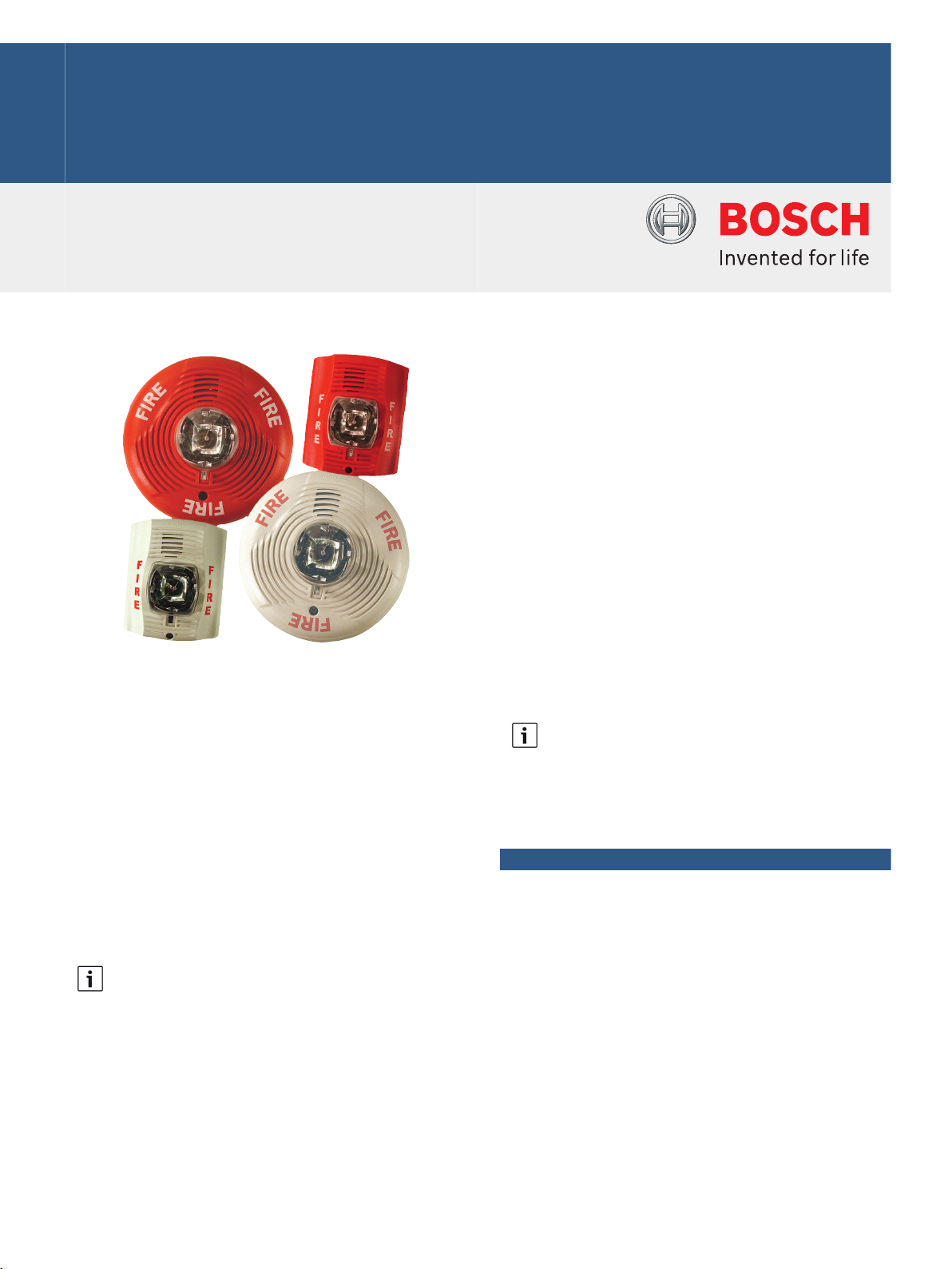
SS‑P Two‑wire Indoor Horn Strobes
www.boschsecurity.com
u Plug‑in design with tamper-resistant construction
u Field‑selectable standard candela (15 cd, 15/75 cd,
30 cd, 75 cd, 95 cd, 110 cd, or 115 cd) settings or
high candela settings (135 cd, 150 cd, 177 cd, or
185 cd)
The SS‑P System Sensor SpectrAlert Advance
notification appliances simplify installations with
features such as plug‑in designs, instant feedback
messages to ensure correct installation of individual
devices, and field‑selectable candela settings. While
there are products specifically designed for use on the
ceiling or the wall, these products are listed to be
used in either application, and the same mounting
plate is used for wall- and ceiling‑mount units.
SpectrAlert products can be used in either DC or
full‑wave rectified (FWR) systems (12 V or 24 V). If
required, the SSMDL or SSMDLW module can be used
to provide synchronization.
Notice
Full‑wave Rectified (FWR) voltage is a
non‑regulated, time‑varying power source that is
used on some power supply and panel outputs.
u Horn rated at 88 dbA or greater at 16 V
u Rotary switch selection for horn tone and one of
three volumes
u Shorting spring on mounting plate for continuity
check before installation
Notice
SpectrAlert products set at 15 cd and 15/75 cd
automatically work on either 12 V or 24 V power
supplies. The products are not listed for 12 V
operating voltages when set to any other candela
settings.
Functions
Horn
The horn has three volume options and an option to
switch between a temporal Code 3 pattern and a
non‑temporal (continuous) pattern. These options are
set by a multiple position switch.
Strobe
When wired as a primary-signaling notification
appliance, the strobe complies with the Americans
with Disabilities Act (ADA) requirements for visible
signaling appliances, flashing at 1 Hz over the strobe's
entire operating voltage range. The strobe light
consists of a xenon flash tube and associated lens and
reflector system.
2 | SS‑P Two‑wire Indoor Horn Strobes
For 24 V applications, the total number of strobes on a
single NAC must not exceed 40, with a maximum loop
resistance of 120 Ω. For 12 V applications, the total
number of strobes must not exceed 12, with a
maximum loop resistance of 30 Ω.
Certifications and approvals
System Sensor holds these Listings and Approvals:
Region Certification
USA UL ULSZ: Audible Signal Appliances
(UL464)
FM SS-P Family
CSFM see our website
Installation/configuration notes
Mounting Considerations
These horn strobes mount on a standard 4‑inch square
back box, a 4‑inch octagon back box, a single‑gang
back box, or a double‑gang back box.
Wiring Considerations
The input terminals on the universal mounting plate
accept solid wires between 12 AWG (2.3 mm) to
18 AWG (1.2 mm).
15/75 cd - Temporal Code 3 Pattern
DC FWR
High dB Setting: 147 mA 155 mA RMS
Medium dB Setting: 144 mA 152 mA RMS
Low dB Setting: 143 mA 151 mA RMS
15/75 cd – Non‑temporal (continuous) Pattern
DC FWR
High dB Setting: 152 mA 161 mA RMS
Medium dB Setting: 145 mA 155 mA RMS
Low dB Setting: 144 mA 154 mA RMS
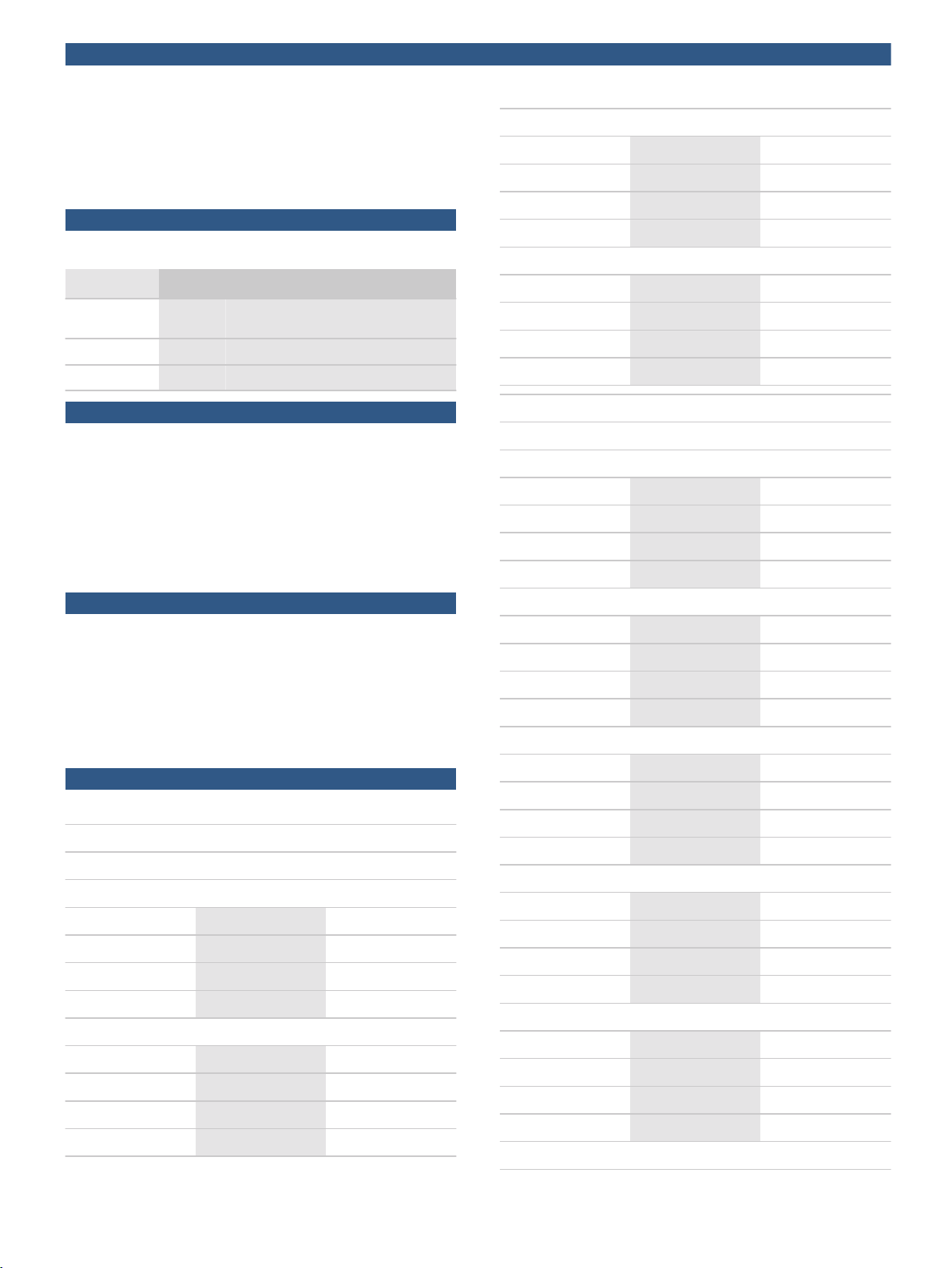
Current Draw, UL maximum at 16 V to 33 V
Standard-candela Models
15 cd - Temporal Code 3 Pattern
DC FWR
High dB Setting: 79 mA 88 mA RMS
Medium dB Setting: 69 mA 78 mA RMS
Low dB Setting: 66 mA 76 mA RMS
Parts included
Quant. Component
1 Horn strobe
1 Universal mounting plate (MP120K)
1 Hardware pack
1 Literature pack
Technical specifications
Electrical
Current Draw, UL maximum at 8 V to 17.5 V
Standard-candela Models only
15 cd - Temporal Code 3 Pattern
DC FWR
High dB Setting: 137 mA 136 mA RMS
Medium dB Setting: 132 mA 129 mA RMS
Low dB Setting: 132 mA 129 mA RMS
15 cd – Non‑temporal (continuous) Pattern
DC FWR
High dB Setting: 141 mA 142 mA RMS
Medium dB Setting: 133 mA 134 mA RMS
Low dB Setting: 131 mA 132 mA RMS
15 cd – Non‑temporal (continuous) Pattern
DC FWR
High dB Setting: 91 mA 103 mA RMS
Medium dB Setting: 75 mA 85 mA RMS
Low dB Setting: 68 mA 80 mA RMS
15/75 cd - Temporal Code 3 Pattern
DC FWR
High dB Setting: 90 mA 97 mA RMS
Medium dB Setting: 80 mA 88 mA RMS
Low dB Setting: 77 mA 86 mA RMS
15/75 cd – Non‑temporal (continuous) Pattern
DC FWR
High dB Setting: 100 mA 112 mA RMS
Medium dB Setting: 85 mA 95 mA RMS
Low dB Setting: 79 mA 90 mA RMS
30 cd - Temporal Code 3 Pattern
DC FWR
High dB Setting: 107 mA 112 mA RMS
Medium dB Setting: 97 mA 103 mA RMS
Low dB Setting: 93 mA 101 mA RMS
30 cd – Non‑temporal (continuous) Pattern
 Loading...