

Bosch SSB255, SSB399, SSB512 Installation And Service Manual
WARNING:
Improper installation, set-up, modication, operation or maintenance of
the heating system can cause personal injury and property damage.
Follow these instructions precisely.
If you require assistance or further information, contact a licensed
contractor / gas tter.
WARNING:
The operating instructions are part of the technical documents that
must be handed over to the owner or operator of the heating system.
Explain to the owner or operator how to use the heating system using
the operating instructions. Make sure that they are familiar with all
required information for the safe and proper operation of the heating
system.
NOTICE:
In Massachusetts, this appliance must be installed by a licensed
plumber or gas tter.
These instructions are available in English and French.
Please keep these instructions for future reference.
Gas Condensing Stainless Steel Boiler
BUDERUS SSB BOILER
SSB255 | SSB399 | SSB512
Installation and Service Instructions for Contractors
6720818454 (2016/02) US

2 |
Contents
1 Key to symbols and safety instructions ..............3
1.1 Key to symbols..................................3
1.2 Safety instructions ...............................3
1.3 General warning.................................3
Product description ..........................4
2
2.1 Introduction.....................................4
2.2 Scope of delivery ................................4
2.3 Proper use .....................................5
2.4 Environmental responsibility / disposal ...............5
2.5 Dimensions and Connections.......................6
2.6 Main components................................9
2.7 Technical data .................................10
2.8 Efficiency Curves ...............................11
Regulations ...............................13
3
3.1 Compliance with standards and regulations...........13
3.2 Operating limits of the boiler.......................13
3.3 Additional regulations for installation in Massachusetts ..13
4.7.5 Approved examples of horizontal and vertical venting
installation ....................................29
4.7.6 Multiple boiler ..................................32
4.7.7 De-rating for altitude installation....................33
Commissioning (for single boiler application) ..........34
5
5.1 Switching the appliance ON/OFF ...................34
5.2 Setting date and time ............................34
5.3 Setting CH and DHW setpoint .....................35
5.4 Boiler information ...............................35
5.5 Parameters list .................................36
5.6 Outdoor reset ..................................36
5.7 Adjusting and setting CO
5.8 Setting frost protection ...........................40
Troubleshooting.............................40
6
6.1 Error codes are shown on the display ...............40
6.1.1 Lockout errors .................................41
6.1.2 Blocking errors .................................42
6.2 Errors not shown on display .......................44
6.3 Sensor Resistance table .........................44
limits ....................39
2
Installation ................................14
4
4.1 Packaging and product identification ................14
4.2 Installation room................................14
4.3 Water Chemistry Guidelines.......................15
4.4 Hydraulic connection ............................15
4.4.1 Low water cut off ...............................16
4.4.2 High limit safety switch ...........................16
4.4.3 Pressure relief valve (PRV) .......................16
4.4.4 Expansion tank.................................16
4.4.5 Pump ........................................17
4.4.6 Condensate removal ............................19
4.5 Electrical connection ............................19
4.5.1 Power supply cable connection ....................19
4.5.2 Access to the electrical terminal strip ................20
4.5.3 Room thermostat connection ......................20
4.5.4 Outside temperature sensor.......................20
4.5.5 Electrical wiring diagram .........................21
4.6 Gas supply piping...............................22
4.6.1 Connection of gas supply piping ...................22
4.6.2 Gas type conversion.............................22
4.7 Venting and air piping system .....................23
4.7.1 General venting and combustion air piping system .....24
4.7.2 Connecting flue gas systems ......................25
4.7.3 Installation of the exhaust and air intake system .......25
4.7.4 Vent and combustion air pipe length [For single boiler
installations] ...................................28
Maintenance . . . . . . . . . . . . . . . . . . . . . . . . . . . . . . .45
7
7.1 General.......................................45
7.2 Maintenance / inspection schedule for end user .......45
7.3 Maintenance / inspection schedule for licensed
contractor / gas fitter.............................45
7.3.1 Gas leaking inspection ...........................45
7.3.2 Check exhaust and combustion air pipe system .......45
7.3.3 Inspection of ignition electrode.....................45
7.3.4 Checking for wiring and connections ................45
7.3.5 Burner gasket inspection .........................45
Applications ...............................46
8
8.1 Multiple zone with indirect tank (pump for each zone) ...46
8.1.1 Settings ......................................47
8.2 Multiple zone with indirect tank (valve for each zone) ...48
8.2.1 Settings ......................................49
8.3 Cascade connection.............................50
8.3.1 Settings ......................................53
Commissioning log for the appliance ...............54
9
Spare parts ................................56
10
6720818454 (2016/02) US SSB
1 Key to symbols and safety instructions
1.1 Key to symbols
Warnings
Warnings in this document are identied by a warning
triangle printed against a grey background.
Keywords at the start of a warning indicate the type and
seriousness of the ensuing risk if measures to prevent the
risk are not taken.
The following keywords are dened and can be used in this document:
DANGER
•
result in death or serious injury.
WARNING
•
could result in death or serious injury.
CAUTION
•
could result in minor to moderate injury.
NOTICE
•
Important information
1.2 Safety instructions
Observe these instructions for your safety.
The burner and control must be correctly installed and adjusted to ensure
safe and economical operation of the gas boiler.
Read this installation and maintenance manual carefully and note the
details on the boiler nameplate before placing the boiler in operation.
Risk of fatal injury from explosion of ammable gases
If you smell gas there is a danger of explosion.
► Never work on gas lines unless you are licensed contractor / gas tter.
► Make sure that a licensed contractor / gas tter installs the boiler,
connects gas and vent, places the boiler in operation, connects the
electrical power, and maintains and repairs the boiler.
► No open ame! No smoking! Do not use lighters.
► Prevent spark formation. Do not operate electrical switches, including
telephones, plugs or door bells.
► Close main gas valve.
► Open doors and windows.
► Warn other occupants of the building, but do not use door bells.
► Call gas company from outside the building.
► If gas can be heard escaping, leave the building immediately, prevent
other people from entering, notify police and re departments from
outside the building
Risk to life from electrical shock.
► Disconnect the power supply to the boiler heating system before
conducting any work on it, e.g. turn off the heating system emergency
switch outside the boiler room.
► It is not sufcient just to turn off the control.
► Do not carry out electrical work unless you are qualied for this type
of work.
► Before servicing disconnect electrical power and lock out to prevent
accidental reconnection.
► Observe and follow the local, state and federal installation regulations.
indicates a hazardous situation which, if not avoided, will
indicates a hazardous situation which, if not avoided,
indicates a hazardous situation which, if not avoided,
is used to address practices not related to personal injury.
This symbol indicates important information where there is
no risk to people or property.
Key to symbols and safety instructions | 3
Risk of fatal injury from ue gas poisoning
Insufcient ventilation or combustion air availability may cause dangerous
ue gas leaks or formation.
► Make sure that inlets and outlets are not reduced in size or closed.
► If faults are not corrected immediately, the boiler must not be operated
until all faults have been corrected.
► Inform the system operator and/or owner of the fault and the danger
in writing.
When working on the ue gas venting equipment or vent damper leakage
of ue gases may endanger the lives of people.
► Carefully observe proper operation of the vent damper. Do not start up
the boiler unless the vent damper is operating properly.
► Use only original parts when replacing parts.
► When replacing the vent damper, install the new one in the specied
position.
Risk to life by poisoning by spillage of ue gases
► If the blocked vent switch trips frequently the fault must be corrected
and proper operation of the blocked vent switch test must be
conducted.
Risk to life by poisoning by leakage of ue gases
► Make sure that the boiler is not equipped with a thermally controlled
ue gas vent damper after the open draft hood.
Risk of fatal injury from neglecting your own safety in case of
emergency, such as with a re
► Never put yourself at risk. Your own safety must always take priority.
Fire danger due to ammable materials or liquids
► Make sure that there are no ammable materials or liquids in the
immediate vicinity of the boiler.
► Maintain a minimum distance of 15 inches from the boiler.
Installation and maintenance
► Observe all current standards and guidelines applicable to the
installation and operation of the boiler heating system as applicable in
your state or local jurisdiction.
► Clean and service the boiler system once a year. Check that the
complete heating system operates correctly.
► Immediately correct all faults to prevent system damage.
► Only use original Bosch spare parts. Losses caused by the use of
parts not supplied by Bosch are excluded from the Bosch warranty.
1.3 General warning
The installation must conform to the requirements of the authority having
jurisdiction or, in the absence of such requirements, to the latest edition
of the National Fuel Gas Code, ANSI Z223.1./NFPA 54. In Canada,
installation must be in accordance with the requirements of CAN/CSA
B149.1, Natural Gas and Propane Installation Code.
Where required by local, state and federal regulations, the system must
comply with the American Society of Mechanical Engineers Safety Code
for Controls and Safety Devices for Automatically Fired Boilers (ASME
CSD-1).
The hot water distribution system must comply with all applicable codes
and regulations. When replacing an existing boiler, it is important to check
the condition of the entire hot water distribution system to ensure safe
operation.
In the Commonwealth of Massachusetts, this appliance must be installed
by a licensed plumber or gas tter. Valves external to the boiler must
be tted with T-handles and condensate piping must be installed in
accordance with the State Plumbing Code.
SSB 6720818454 (2016/02) US
4 | Product description
NOTICE:
► This boiler must be installed by a licensed contractor/ gas tter.
Failure to do so shall void the product warranty.
► The boiler is intended only for the use for which it was specically
designed and built. Bosch is hereby excluded from any liability for
damages caused to persons, animals or property resulting from
installation errors, improper adjustment, maintenance or use.
► In order to ensure safety and correct operation, the installation shall
always take place in full compliance with the applicable codes and
following with the instructions provided by the manufacturer, and must
always be carried out by a licensed contractor / gas tter only.
► The equipment must be installed in appropriate place and in
combination with appropriate systems as specied by code.
► The unit may be exposed to temperatures between 5 deg F (-15°C)
and 150 deg F (65°C) in its original packaging. Do not expose the
unit to weather without the protection of the original packaging until
the boiler has been properly installed. Until then there is no frost
protection for the boiler.
► After removing the packaging check the integrity and completeness of
delivery and in case of non-compliance, contact your dealer.
► If there is a water loss, disconnect the boiler from the main power
supply, close the water supply and immediately call technical
assistance or installer/local contractor.
► Periodically check that the condensate drain is free from obstruction.
► Periodically check the system pressure. System pressure should be
checked when the system is in standby mode and no call for heat is
present.
► Maintenance is mandatory and shall be carried out at least once a
year.
► This manual shall be read carefully, in order to install and operate the
boiler appropriately, and safely.
► Boiler installations, settings and service should only be performed by
experienced licensed contractor / gas tter. End Users should only
make adjustments with the assistance of a licensed contractor / gas
tter.
► Any maintenance operation or service before disconnecting the boiler
from the main power supply is forbidden.
► Do not remove or modify safety equipment.
► Do not pull or twist the electrical wires, from the boiler, even if the
device is disconnected from the main power supply.
► Do not obstruct or reduce the ventilation openings.
► Do not install the unit outdoors.
► Do not leave any combustibles or containers of ammable substances
in the room where the boiler is installed.
► Keep packing material out of reach of children as it can be potentially
dangerous. It must be disposed of as required by law.
► The opening of metal casing of the device and removing of the cover
are prohibited to the end user. Any service on the boiler must be
carried out by authorized personal.
► It’s prohibited to dispose the product as domestic waste. The
separate disposal of a household appliance avoids possible negative
consequences for the environment and human health deriving from
inappropriate disposal and allows to recover the materials it is made
of in order to achieve signicant savings in energy and resources.
2 Product description
2.1 Introduction
• The gas-red condensing SSB boilers are designed to be used in
central heating systems. Any other use is prohibited.
• This boiler can be connected to an indirect storage tank for the
production of domestic hot water.
• There are several options for venting including single pipe, two pipe
and concentric see section “4.7 Venting and air piping system” for
details.
• The quality of the system water is very important. Poor water quality
can damage heating systems and boilers due to scale formation and
corrosion (see water quality section).
• The boilers can also function directly with any hydronic emitter.
When installing the boiler and system connections, the installer must
consider the total head loss and ow rates in order to adequately size
piping and circulator pumps.
• The SSB boiler can be connected to a room thermostat.
• An outdoor air temperature sensor must also be connected to the
boiler for an outdoor reset supply temperature control for increased
fuel efciency and comfort.
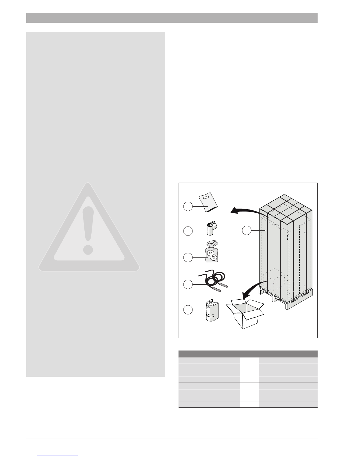
2.2 Scope of delivery
2
3
6
.5
4
6.75
1
5
6
Fig. 1 Scope of delivery
Component Qty Packaging method
[1] Gas condensing boiler 1 Pallet
[2] Set of documents for
appliance
[3] Safety relief valve 1 Cardboard box on pallet
[4] LP conversion kit 1 Plastic package
[5] Universal Sensor for LLH
or DHW
[6] Outdoor sensor 1 Cardboard box on pallet
1 Plastic package
2 Cardboard box on pallet
6720818454 (2016/02) US SSB

2.3 Proper use
► The SSB Boilers are designed for large residential, commercial and
light industrial applications.
► The SSB 512 is delivered in compliance with CSD-1 Commercial
Applications.
► The appliance may only be installed in closed loop hot water central
heating systems.
► Any other purpose is considered improper use. Any resulting damage
is excluded from the manufacturer’s warranty.
► In some heating applications like pool, spa or process water heating a
heat exchanger must to be installed.
2.4 Environmental responsibility / disposal
Environmental responsibility is one of the fundamental company policies
of the Bosch Group.
We regard quality of performance, economy and environmental
responsibility as equal objectives. Environmental protection laws and
regulations are strictly adhered to.
To protect the environment, we use the best possible technology and
materials taking into account economic points of view.
Packaging
All packaging materials used are environmentally-friendly and recyclable.
Product description | 5
SSB 6720818454 (2016/02) US
6 | Product description
19 19/32” (498mm)
17 21/32” (448mm)
13 11/16” (348mm)
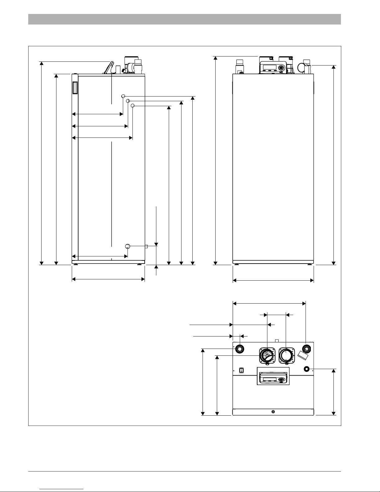
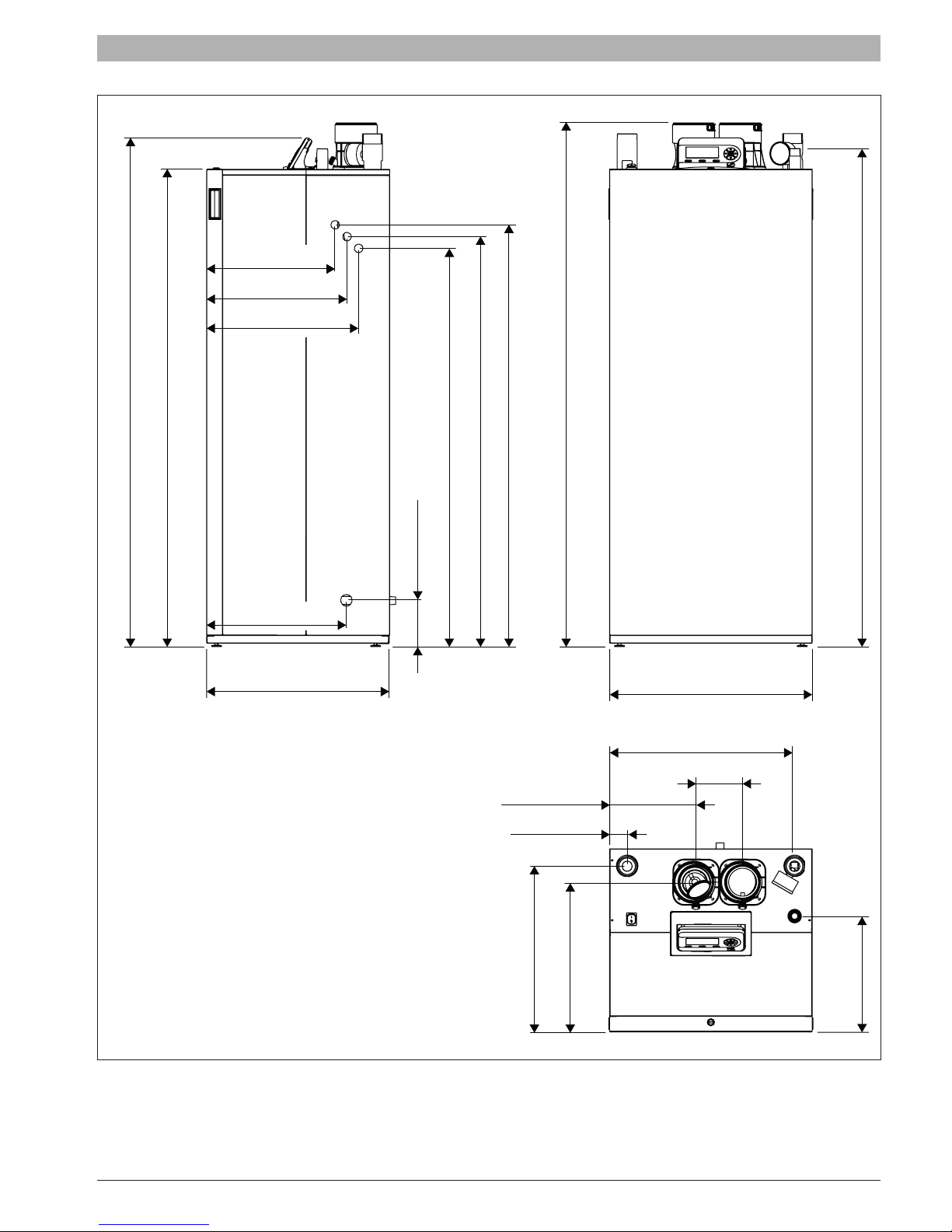
2.5 Dimensions and Connections
15 7/32” (386mm)
16 19/32” (422mm)
18” (457mm)
F
60 3/16” (1529mm)
56 7/16” (1434mm)
16 17/32” (420mm)
21 21/32” (550mm)
61 9/16” (1564mm)
49 27/32” (1266mm)
48 7/16” (1231mm)
47 1/32” (1195mm)
G
5 7/16” (138mm)
58 7/8” (1496mm)
23 31/32” (609mm)
21 5/8” (549mm)
5 1/2” (140mm)
10 1/16” (256mm)
2 3/32” (53mm)
B
A
DE
C
Fig. 2 SSB255 (dimension in inches [mm])
A System supply - 1” 1/2 NPT
B System return - 1” 1/2 NPT
C Gas inlet - 1” NPT
6720818454 (2016/02) US SSB
D Flue exhaust - 3” (80mm)
E Intake air - 3” (80mm)
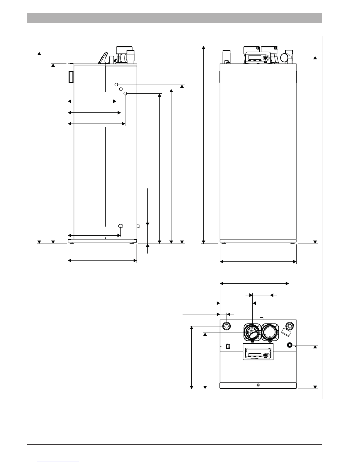
19 19/32” (498mm)
17 21/32” (448mm)
13 11/16” (348mm)
15 7/32” (386mm)
16 19/32” (422mm)
18” (457mm)
Product description | 7
F
60 3/16” (1529mm)
56 7/16” (1434mm)
16 17/32” (420mm)
21 21/32” (550mm)
61 9/16” (1564mm)
49 27/32” (1266mm)
48 7/16” (1231mm)
47 1/32” (1195mm)
G
5 7/16” (138mm)
58 7/8” (1496mm)
23 31/32” (609mm)
21 5/8” (549mm)
5 1/2” (140mm)
10 1/16” (256mm)
2 3/32” (53mm)
B
A
DE
C
Fig. 3 SSB399 (dimension in inches [mm])
A System supply - 1” 1/2 NPT
B System return - 1” 1/2 NPT
C Gas inlet - 1” NPT
SSB 6720818454 (2016/02) US
D Flue exhaust - 4” (110mm)
E Intake air - 4” (110mm)
8 | Product description
19 19/32” (498mm)
17 21/32” (448mm)
13 11/16” (348mm)
15 7/32” (386mm)
16 19/32” (422mm)
F
18” (457mm)
60 3/16” (1529mm)
56 7/16” (1434mm)
16 17/32” (420mm)
21 21/32” (550mm)
61 9/16” (1564mm)
49 27/32” (1266mm)
48 7/16” (1231mm)
47 1/32” (1195mm)
G
5 7/16” (138mm)
58 7/8” (1496mm)
23 31/32” (609mm)
21 5/8” (549mm)
5 1/2” (140mm)
10 1/16” (256mm)
2 3/32” (53mm)
B
A
DE
C
Fig. 4 SSB512 (dimension in inches [mm])
A System supply - 2” NPT
B System return - 2” NPT
C Gas inlet - 1” NPT
6720818454 (2016/02) US SSB
D Flue exhaust - 4” (110mm)
E Intake air - 4” (110mm)
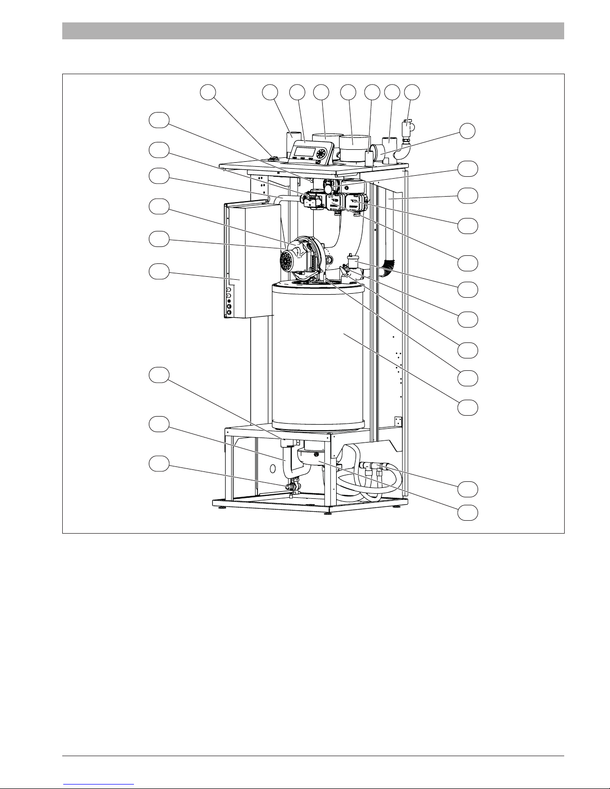
2.6 Main components
29
28
Product description | 9
1 2 3 4 65 7 8
9
27
26
25
24
23
22
10
11
12
13
14
15
16
17
18
21
Fig. 5 SSB512 (main components)
[1] Main power switch
[2] System return
[3] Removable display
[4] Flue exhaust
[5] Intake air
[6] Gas inlet
[7] System supply
[8] Pressure Relief Valve
[9] Tridicator
[10] Air pressure switch
[11] Heat exchanger supply pipe
[12] Max pressure switch [For SSB 512 Only]
[13] Min pressure switch [For SSB 512 only]. Location should be burner
side of gas valve.
[14] Automatic air vent
19
20
[15] Low water cut off probe
[16] High limit temp. safety switch
[17] Spark electrode
[18] Heat exchanger
[19] Condensate manifold
[20] Air pressure switch connection
[21] Low point drain valve
[22] Heat exchanger return pipe
[23] Return temperature probe
[24] Wiring Control Panel
[25] Main shut off gas valve
[26] Fan
[27] Gas pipe
[28] Gas valve
[29] Flue gas probe
SSB 6720818454 (2016/02) US
10 | Product description
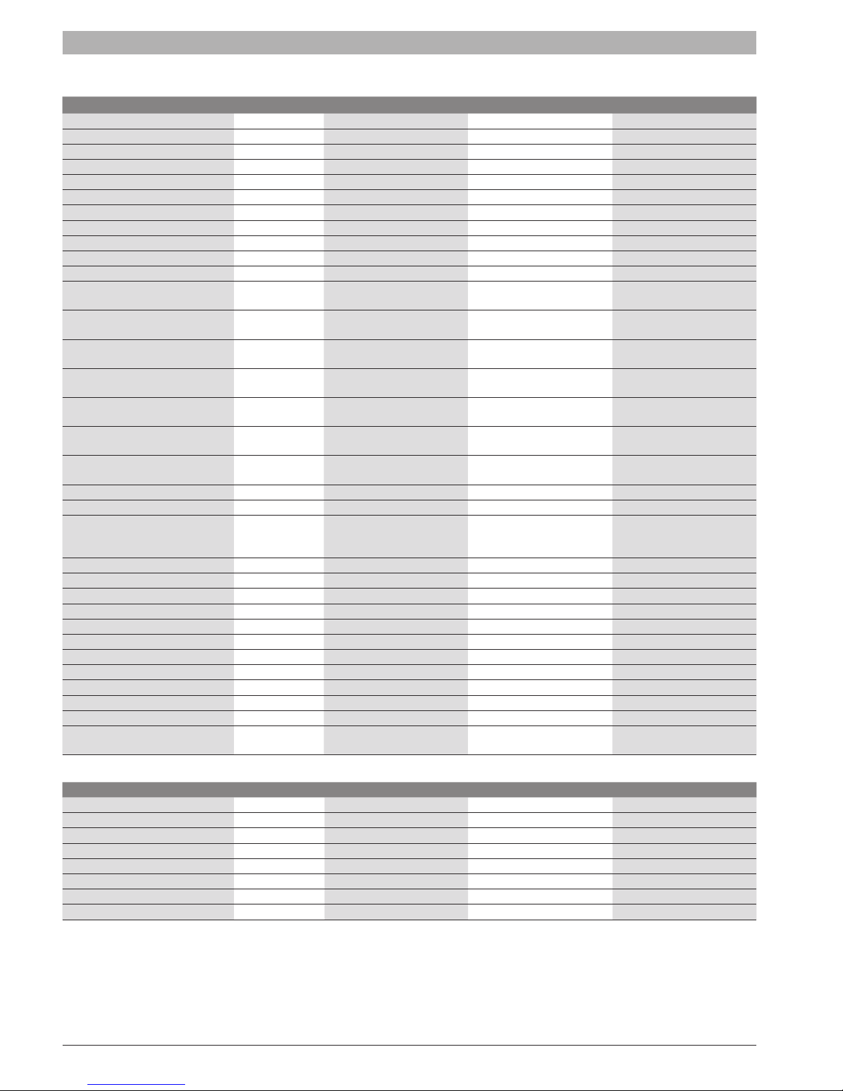
2.7 Technical data
Unit SSB255 SSB399 SSB512
Boiler Category ASME Sect.IV ASME Sect.IV ASME Sect.IV
Type of Gas Natural Gas, Propane * Natural Gas, Propane * Natural Gas, Propane *
Max input rate BTU/hr (kW) 255,900 (75) 399,000 (117) 512,000 (150)
Min input rate BTU/hr (kW) 51,180 (15) 79,800 (23.4) 102,400 (30)
Turndown Rate (%) 5:1 (20 %) 5:1 (20 %) 5:1 (20 %)
Gas Connections (NPT) Ø Inch 1” 1’’ 1’’
Max. NG Pressure Inch W.C. (mbar) 10.5 (26.15) 10.5 (26.15) 10.5 (26.15)
Min. NG Pressure Inch W.C. (mbar) 3.5 (8.72) 3.5 (8.72) 3.5 (8.72)
Max. LPG Pressure Inch W.C. (mbar) 13 (32.3) 13 (32.3) 13 (32.3)
Min. LPG Pressure Inch W.C. (mbar) 8 (19.9) 8 (19.9) 8 (19.9)
Water Connections Ø Inch 1 ½ “ 1 ½” 2’’
Max. Allowable Working Pressure
(MAWP)
Recommended water ow @ max
power (∆T 36 °F / 20 °C)
Max water ow @ max power
(∆T 27 °F / 15 °C)
Min water ow @ max power
(∆T 54 °F / 30 °C)
Min water ow @ min power
(∆T 27 °F / 15 °C)
Water Pressure Drop @
recommended water ow
Water Pressure Drop @ max water
ow
Water Volume Gallon (liter) 4.0 (15.2) 4.5 (17.0) 6.0 (23.0)
Vent/Air Intake Connections Ø Inch (Ø mm) 3 (80) 4 (100) 4 (100)
Vent Materials
Max operating temperature °F (°C) 194 (90) 194 (90) 194 (90)
Max HE allowable temperature °F (°C) 210 (98.9) 210 (98.9) 210 (98.9)
Ambient storage temperature dry °F (°C) 5 to 150 (-15 to 65) 5 to 150 (-15 to 65) 5 to 150 (-15 to 65)
Ambient functioning temperature °F (°C) 32 to 120 (0 to 49) 32 to 120 (0 to 49) 32 to 120 (0 to 49)
Ambient Relative Humidity [RH] % RH Minimum 30%, Maximum 90% Minimum 30%, Maximum 90% Minimum 30%, Maximum 90%
Surface area heat exchanger SQFT (m
Standard Listings & Approvals CSA, ASME, AHRI CSA, ASME, AHRI CSA, ASME, AHRI
Electrical Req. 120VAC/1PH/60Hz 2 FLA** 2.5 FLA** 2.5 FLA**
Noise rating dB 46 47 48
Weight (dry) lbs (kg) 198 (90) 220 (100) 242 (110)
Min. clearance to combustibles *** Inch (mm) 2” (50.8) 2” (50.8) 2” (50.8)
Dimension WxHxD
PSI (bar) 80 (5.5) 80 (5.5) 80 (5.5)
3
GPM (m
/h) 14.2 (3.2) 22.2 (5.0) 28.4 (6.5)
3
GPM (m
/h) 18.9 (4.3) 29.5 (6.7) 37.9 (8.6)
3
GPM (m
/h) 9.5 (2.2) 14.8 (3.4) 18.9 (4.3)
3
GPM (m
/h) 3.8 (0.9) 5.9 (1.3) 7.6 (1.7)
Feet Head (mbar) 3.8 (114) 8.3 (250) 21.7 (650)
Feet Head (mbar) 6.4 (190) 13.8 (410) 37.73 (1120)
CPVC, PVC, PP, PP Flex,
Stainless Steel AL29-4C
IPEX type IIA & IIB
2
) 22.0 (2.0) 27.2 (2.5) 43.0 (4.0)
Inch
(mm)
23 31/32” x 61 9/16” x 21 21/32”
(609x1564x550)
CPVC, PVC, PP, PP Flex,
Stainless Steel AL29-4C
IPEX type IIA & IIB
23 31/32” x 61 9/16” x 21 21/32”
(609x1564x550)
CPVC, PVC, PP, PP Flex,
Stainless Steel AL29-4C
IPEX type IIA & IIB
23 31/32” x 61 9/16” x 21 21/32”
(609x1564x550)
AHRI certied ratings
Unit SSB255 SSB399 SSB512
Input MBH 255 399 511.8
Heating Capacity MBH 237.0 n/a n/a
Gross Output MBH n/a 386.0 495.0
AFUE % 96 n/a n/a
Combustion Efciency % n/a 97.6 95.4
Thermal efciency % n/a 96.9 96.8
Net rating MBH 206.0 336.0 430.0
2 % 10.2 10.1 9.5
CO
(*) With conversion.
(**) FLA (Full Load Amperage) - maximum current drawn by the boiler without pumps.
(***) The 2” minimum clearance is required for all sides of the boiler. The boiler may be installed on combustible (wood) oors excluding carpets.
See Fig. 9 for minimum clearance recommendation for serviceability.
6720818454 (2016/02) US SSB
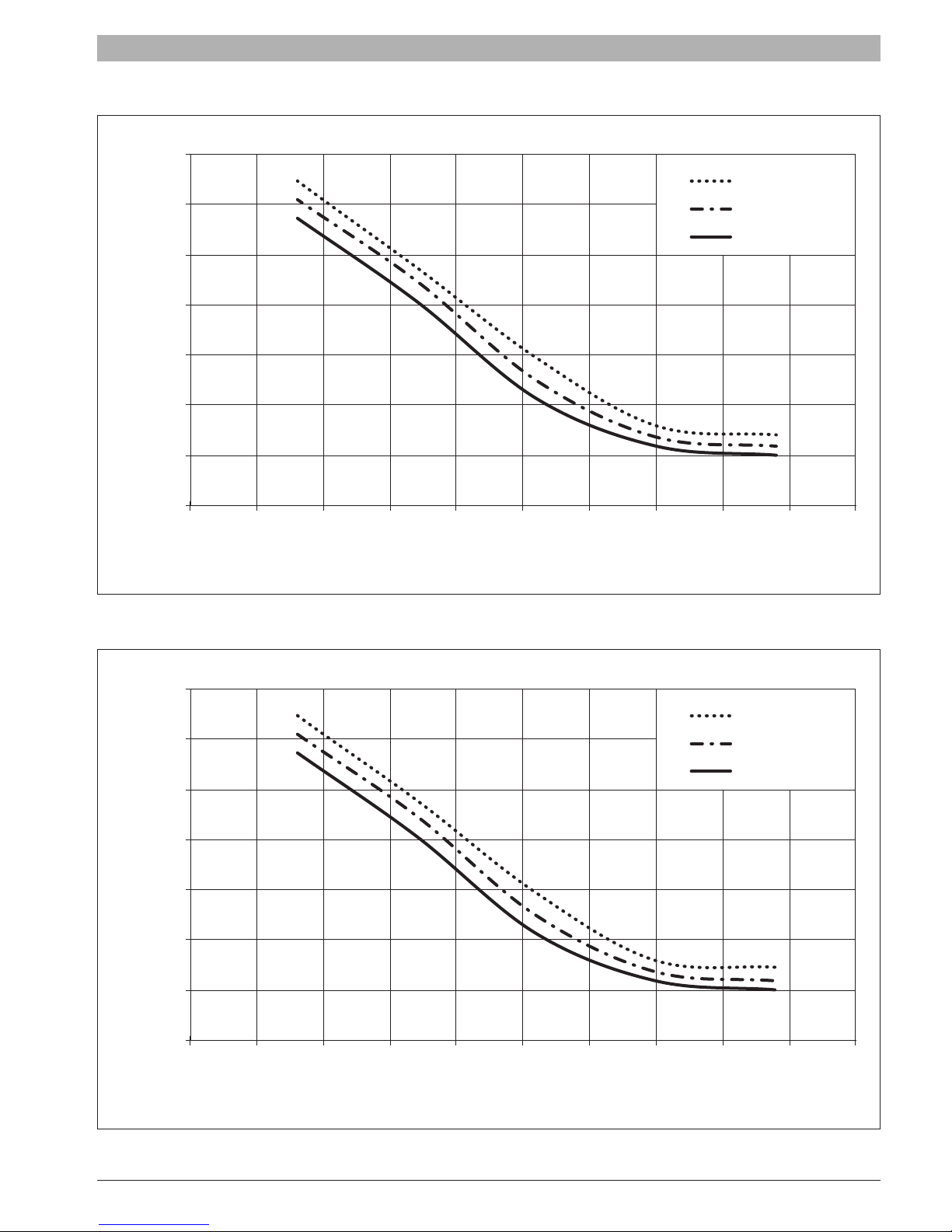
2.8 Efciency Curves
100%
98%
Product description | 11
20% input
30% input
96%
94%
92%
Thermal Efficiency
90%
88%
86%
70 80 90 100 110 120 130 140 150 160 170
Fig. 6 Thermal Efciency Curves SSB255*
* Thermal Efciency curve is for reference only as this is a residential boiler
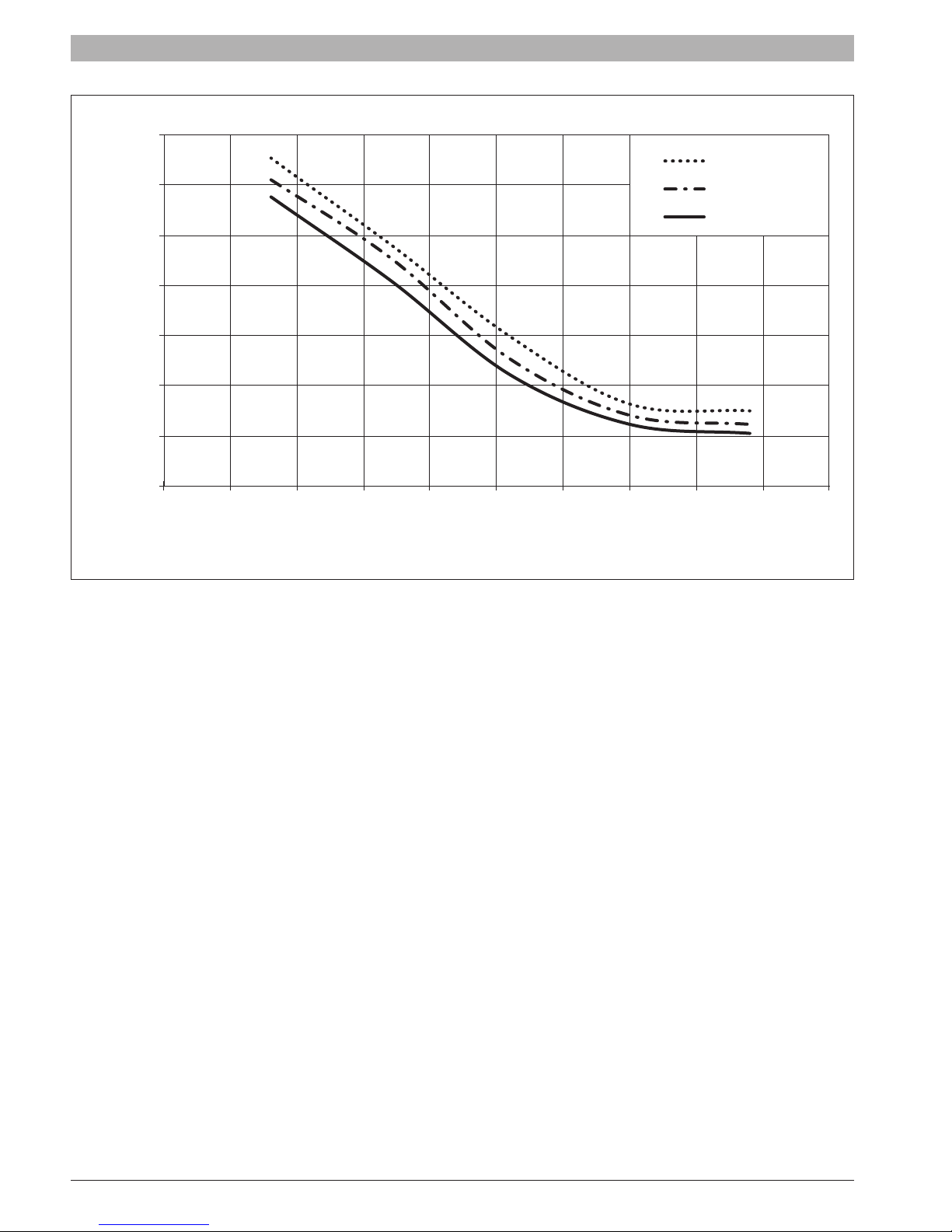
100%
100% input
Return Water Temperature (°F) @ 36 Degree Rise
98%
96%
94%
92%
Thermal Efficiency
90%
88%
86%
70 80 90 100 110 120 130 140 150 160 170
Fig. 7 Thermal Efciency Curves SSB399
20% input
30% input
100% input
Return Water Temperature (°F) @ 36 Degree Rise
SSB 6720818454 (2016/02) US
12 | Product description
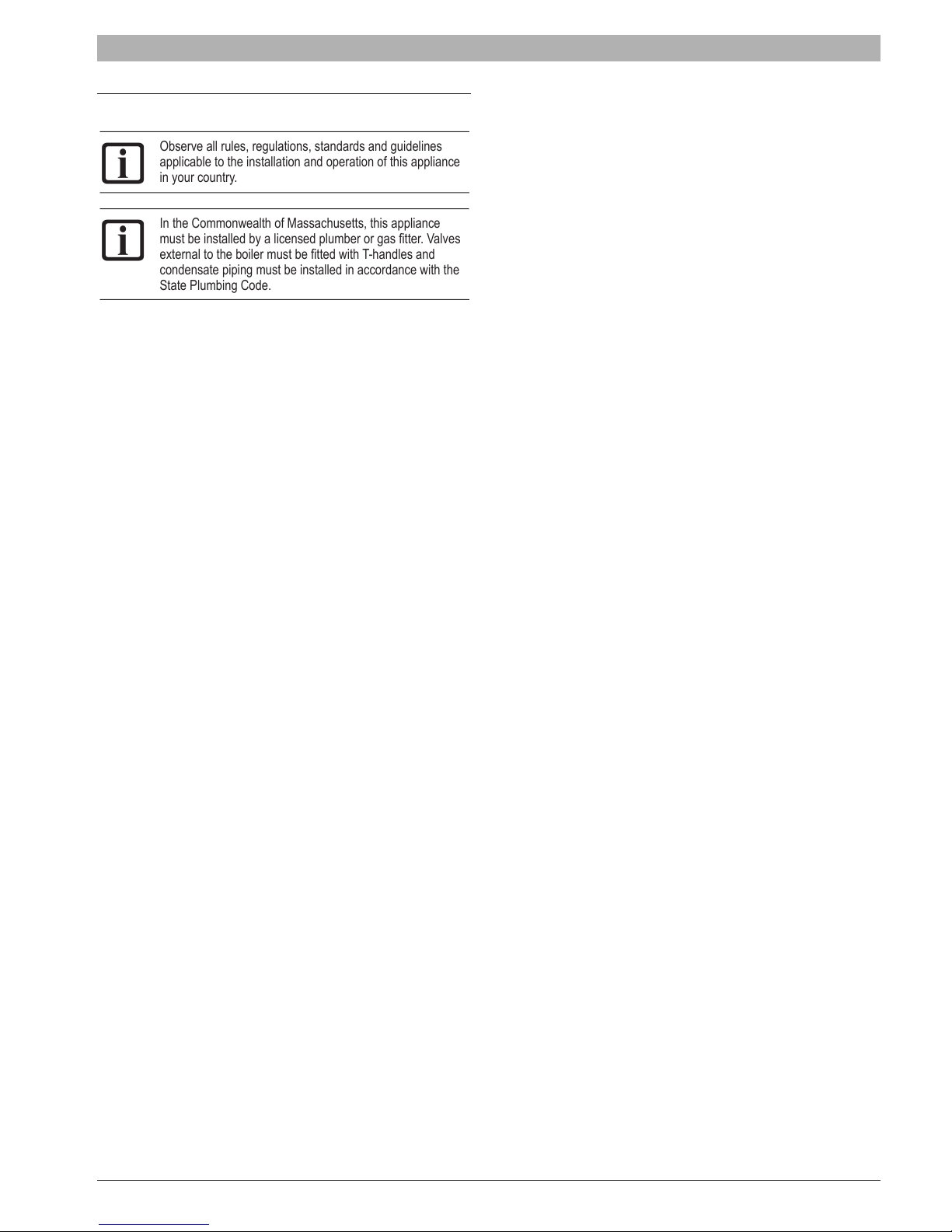
100%
98%
20% input
30% input
96%
94%
92%
Thermal Efficiency
90%
88%
86%
70 80 90 100 110 120 130 140 150 160 170
Fig. 8 Thermal Efciency Curves SSB512
100% input
Return Water Temperature (°F) @ 36 Degree Rise
6720818454 (2016/02) US SSB
3 Regulations
Observe all rules, regulations, standards and guidelines
applicable to the installation and operation of this appliance
in your country.
In the Commonwealth of Massachusetts, this appliance
must be installed by a licensed plumber or gas tter. Valves
external to the boiler must be tted with T-handles and
condensate piping must be installed in accordance with the
State Plumbing Code.
3.1 Compliance with standards and regulations
The installation must conform to the requirements of the authority having
jurisdiction or, in the absence of such requirements, to the latest edition
of the National Fuel Gas Code, ANSI Z223.1./NFPA 54. In Canada,
installation must be in accordance with the requirements of CAN/CSA
B149.1, Natural Gas and Propane Installation Code.
This condensing gas boiler complies in its design and mode of operation
with the American National Standard ANSI Z21.13/CSA4.9, latest edition
for Gas Fired Low Pressure Steam and Hot Water Boilers.
Other conrmed approvals and certications are indicated by labels on
the boiler.
Where required by the authority having jurisdiction, the installation
must conform to the Standard for Controls and Safety Devices for
Automatically Fired Boilers, ANSI/ASME CSD-1.
Install CO detectors per local regulations. Boiler requires yearly
maintenance (see section “7 Maintenance”).
3.2 Operating limits of the boiler
The heat exchanger has been designed and certied in accordance with
the ASME Boiler and Pressure Vessel Code, Section IV.
The hot water distribution system must comply with all applicable codes
and regulations. When replacing an existing boiler, it is important to
check the condition of the entire hot water distribution system to ensure
safe operation. Common practice calls for inspecting an existing system
in its entirety and bringing it up to code. All pipework should be properly
cleaned and ushed.
3.3 Additional regulations for installation in
Massachusetts
(a) For all side wall horizontally vented gas fueled equipment installed in
every dwelling, building or structure used in whole or in part for residential
purposes, including those owned or operated by the Commonwealth and
where the side wall exhaust vent termination is less than seven (7) feet
[2150 mm] above nished grade in the area of the venting, including but
not limited to decks and porches, the following requirements shall be
satised:
• INSTALLATION OF CARBON MONOXIDE DETECTORS. At the
time of installation of the side wall horizontal vented gas fueled
equipment, the installing plumber or gastter shall observe that a hard
wired carbon monoxide detector with an alarm and battery backup is installed on the oor level where the gas equipment is to be
installed. In addition, the installing plumber or gastter shall observe
that a battery operated or hard wired carbon monoxide detector
with an alarm is installed on each additional level of the dwelling,
building or structure served by the side wall horizontal vented gas
fueled equipment. It shall be the responsibility of the property owner
to secure the services of qualied licensed professionals for the
installation of hard wired carbon monoxide detectors.
- In the event that the side wall horizontally vented gas fueled
equipment is installed in a crawl space or an attic, the hard wired
carbon monoxide detector with alarm and battery back-up may be
Regulations | 13
installed on the next adjacent oor level.
- In the event that the requirements of this subdivision can not be
met at the time of completion of installation, the owner shall have
a period of thirty (30) days to comply with the above requirements;
provided, however, that during said thirty (30) day period, a
battery operated carbon monoxide detector with an alarm shall be
installed.
• APPROVED CARBON MONOXIDE DETECTORS. Each carbon
monoxide detector as required in accordance with the above
provisions shall comply with NPA 720 and be ANSI/UL 2034 listed and
IAS certied.
• SIGNAGE. A metal or plastic identication plate shall be permanently
mounted to the exterior of the building at a minimum height of eight (8)
feet above grade directly in line with the exhaust vent terminal for the
horizontally vented gas fueled heating appliance or equipment. The
sign shall read, in print size no less than one-half (.) inch in size, “GAS
VENT DIRECTLY BELOW. KEEP CLEAR OF ALL OBSTRUCTIONS”.
• INSPECTION. The state or local gas inspector of the side wall
horizontally vented gas fueled equipment shall not approve the
installation unless, upon inspections, the inspector observes carbon
monoxide detectors and signage installed in accordance with the
provisions of 248 CRM 5.08(2)(a) 1 through 4.
(b) EXEMPTIONS: The following equipment is exempt from 248 CRM
5.08(2)(a) 1 through 4:
• The equipment listed in Chapter 10 entitled “Equipment Not Required
To Be Vented” in the most current edition of NFPA 54 as adopted by
the board; and
• Product Approved side wall horizontally vented gas fueled equipment
installed in a room or structure separate from the dwelling, building or
structure used in whole or in part for residential purposes.
(c) MANUFACTURERS REQUIREMENTS - GAS EQUIPMENT
VENTING SYSTEM REQUIRED. When the manufacturer of Product
Approved side wall horizontally mounted gas equipment provides a
venting system design or venting system components with the equipment,
the instructions provided by the manufacturer for the installation of the
equipment and venting shall include:
• Detailed instructions for the installation of the venting system or the
venting system components; and
• A complete parts list for the venting system design or venting system.
(d) MANUFACTURERS REQUIREMENTS - GAS EQUIPMENT
VENTING SYSTEM NOT PROVIDED. When the manufacturer of Product
Approved side wall horizontally vented gas fueled equipment does not
provide the parts for the venting of ue gases, but identies special
venting systems, the following requirements shall be satised by the
manufacturer:
• The referenced special venting systems shall be included with the
appliance or equipment installation instructions; and
• The special venting systems shall be Product Approved by the Board,
and the instructions for that system shall include a parts list and
detailed installation instructions.
(e) A copy of all instructions for all Product Approved side wall horizontally
vented gas fueled equipment, all venting instructions, all parts lists for
venting instructions, and/or venting design instructions shall remain with
the appliance or equipment at the completion of the installation.
SSB 6720818454 (2016/02) US
14 | Installation
4 Installation
4.1 Packaging and product identication
The SSB is delivered strapped to a pallet, packed and protected in a
cardboard carton.
The recommended clearance for ease of installation and service are
illustrated in the following picture:
NOTICE: The packaging shows the characteristics of the
product: model, power, fuel type and version. In case of
deviation from the order, contact your local dealer.
After removing the packaging check the condition and
completeness of delivery.
WARNING: Keep the packing material out of reach of
children as it may be dangerous.
Dispose of packaging in an environmentally responsible
manner.
In order to ensure proper product identication do not
remove or tamper with any product identication tags or
labels.
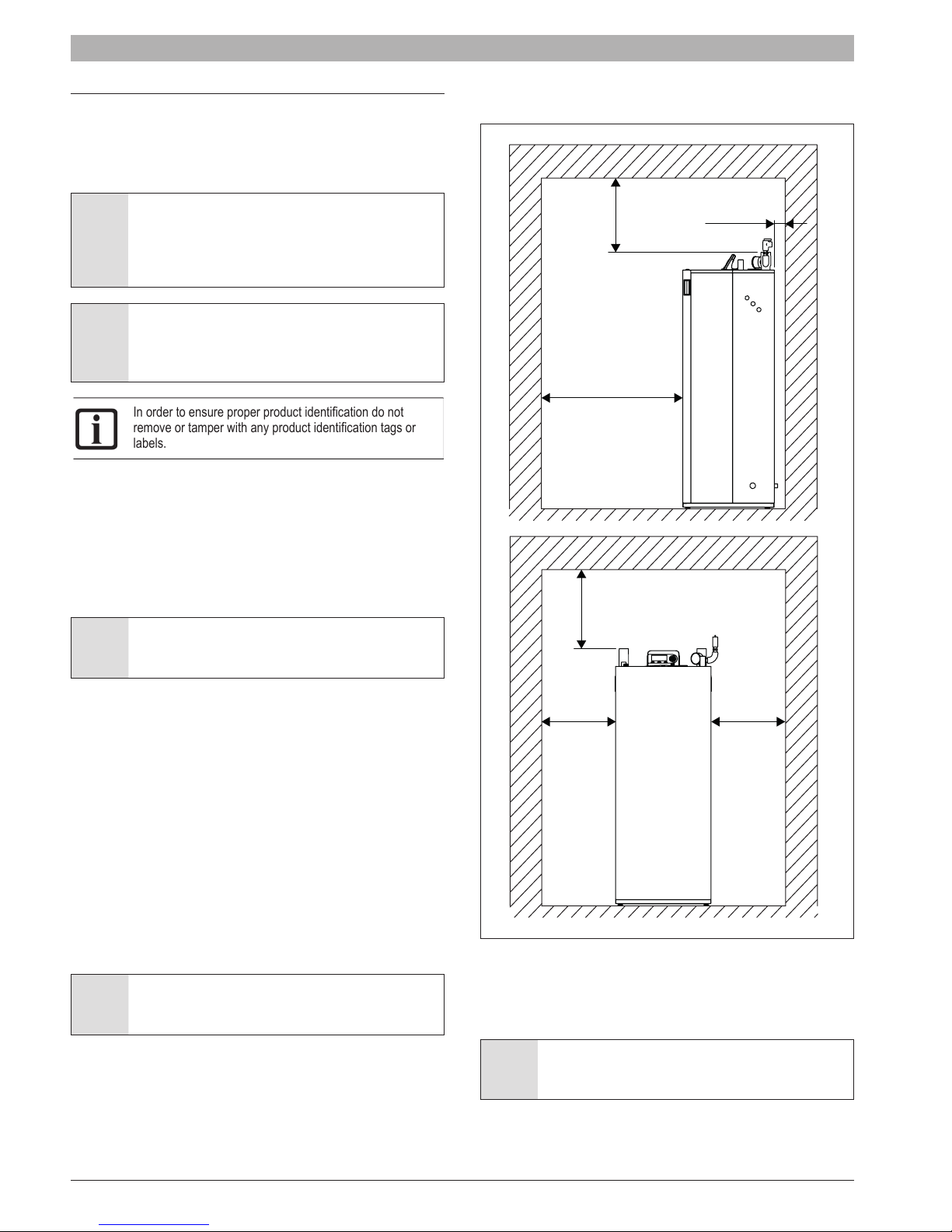
4.2 Installation room
The boiler must be installed in rooms that comply with all local, state and
federal codes and laws. Before commissioning the boiler verify exhaust
ue and terminations are properly sealed and secured.
• Adequate combustion air and ventilation is required for safe and
proper installation of the boiler, regardless whether the combustion air
is taken from the outside (Direct Vent, sealed combustion) or inside
(room air for combustion).
WARNING: Insufcient ventilation of the boiler room can
lead to high air temperatures and lead to risk of personal
injury or death from ue gas poisoning!
2” (50mm)
20” (500mm)
40” (1000mm)
20” (500mm)
• Make sure that intake and exhaust openings are sufciently sized and no
reduction or closure of openings takes place. If these are not provided, do
not operate the boiler (see section “4.7.2 Connecting ue gas systems”).
• The heating units cannot be installed outdoors. NEVER place this
appliance in a location that would subject it to temperatures at or near
freezing or temperature that exceed 120°F (49°C) while in operation.
Failure to properly locate this unit can result in premature failure.
• This appliance must be installed in a location so that any water
leaking from the unit or piping connections or relief valve openings
will not cause damage to the area surrounding the unit or any lower
oors in the structure. When such locations cannot be avoided, it
is recommended that a suitable drain pan, adequately drained, be
installed under the boiler. The pan must not restrict combustion air ow.
• When installed in a room with thin ooring, resonating noises may
occur. Isolate the boiler from direct contact with the oor to minimize
noise transmission.
• Do not allow excessive dust to collect on the appliance.
WARNING: If the information in these instructions is not
followed exactly, a re or explosion may result causing
property damage, personal injury or death.
• Do not store or use gasoline or other ammable vapors and liquids in
the proximity of this or any other appliance.
• Installation and service must be performed by a qualied installer,
service agency or the gas supplier.
• Please consider the space needed for accessibility to safety and
control devices and for performing maintenance operations.
4” (100mm) 4” (100mm)
Fig. 9 Recommended minimum clearances for installation and
servicing (dimension in inches [mm])
2” (50.8 mm) clearance from combustibles is permitted, but respect the
clearance in Fig. 9 for serviceability”. The boiler can be installed on a
combustible (wood) oor excluding carpets.
NOTICE: This device is equipped with a freeze protection
function. For further information see section “5.8 Setting
frost protection”.
6720818454 (2016/02) US SSB

Installation | 15
4.3 Water Chemistry Guidelines
NOTICE: If using anti-freeze:
► Follow the boiler manufacturer’s instructions on
antifreeze concentration.
► Frost protection and inhibitor level has to be checked
annually during the regular scheduled maintenance of
the condensing boiler.
NOTICE: System damage!
► It is the installer’s responsibility to ensure that the
heating system is compatible with the boiler type and
size installed.
► pH-value of the heating water to be kept between 6.5
and 9.
To avoid any presence of oxygen in the system, it is advised to prevent as
little as possible air during installation. Usual spots where air is most likely
to seep in are: gaskets, pumps, air vents and O-rings gaskets. Using
an automatic water ll system exposes the system to fresh oxygenated
water. In commercial applications it is recommended to install a water
meter to measure the introduction of fresh water into the system.
A minimum water pressure is required for optimum performance.
Minimum water pressure required: 7.25 psi (0.5 bar).
Before and during assembly, the system must be kept free of impurities,
construction dust, sand, copper dust, grease, carbon deposits, etc., as
well as welding ux residue. In any of these instances, the old system
must be rinsed with clear water mixed with a highly concentrated rinse
agent.
For freeze protection use only propylene glycol, with scale inhibitors, with
a maximum volume [concentration] of 40% of glycol.
NOTICE: DO NOT use PVC for exhaust venting when using
anti-freeze in the primary circuit of the boiler. Use CPVC, PP
or stainless steel only!
Water hardness must fall within the following limits:
50 ppm of CaCO
► Use only untreated water to ll the system.
► Do not use TSP (tri-sodium phosphate).
► Do not use ll water treated with salt bedding type exchangers (ion
exchanger).
► Never introduce non-approved boiler treatment or similar additives.
► Only use ll water with a hardness below 7 grains.
► Filling with chlorinated water is acceptable if chlorine levels are below
100 ppm.
► Consult a local water treatment specialist for recommendations if any
of the above is outside the stated ranges.
► When using oxygen permeable PEX, the system must be separated
from the boiler by a heat exchanger.
► A correctly sized and working expansion vessel must be installed.
► Do not exceed the maximum permissible ow rate through the boiler.
► Excessive ow can cause erosion damage to the heat exchanger.
► Eliminate System Leaks:
Continuous addition of make-up water will constantly add oxygen to
the system and lead to corrosion. All system leaks must be repaired.
< (alkali strength) < 150 ppm of CaCO3.
3
In the following table are listed the chemical water specications.
Parameters Units Value
General feature - Colorless, no sediment
Dissolved Oxygen mg/l < 0,05
Total iron (Fe) mg/l < 0,3
Total copper (Cu) mg/l < 0,1
Na
2SO3
N
2H4
PO
4
Tab. 1 Water specication
mg/l < 10
mg/l < 3
mg/l < 15
4.4 Hydraulic connection
Hydraulic connection are shown in Fig. 2, Fig. 3 and Fig. 4. In the
following table are listed the pipe dimension for each model:
Model
SSB255 1-1/2” NPT male 1-1/2” NPT male
SSB399 1-1/2” NPT male 1-1/2” NPT male
SSB512 2” NPT male 2” NPT male
• Do not use cleaning uids that are not compatible with the boiler
materials, including acids (e.g. hydrochloric acid and similar ones) at
any concentration
• Introducing fresh water to the system increases the oxygen presence
and can cause corrosion of metallic components. Immediately repair
any drips or leaks in the system to avoid constant introduction of air
into the system.
• Do not use the water contained in the boiler for domestic use or as
drinking water or within swimming pools.
• Excessive uctuation in pressure changes in the system can cause
fatigue and stress on the heat exchanger. This is detrimental to the
integrity of the boiler and system components, it is mandatory to
maintain a constant operating pressure.
Ø Water supply
connection
NOTICE: Before connecting the boiler to the heating
system, ush the heating system to remove sediment, ux,
dirt, and other foreign matter. The heat exchanger may be
damaged by sediment or corrosion.
Ø Water return
connection
SSB 6720818454 (2016/02) US
16 | Installation
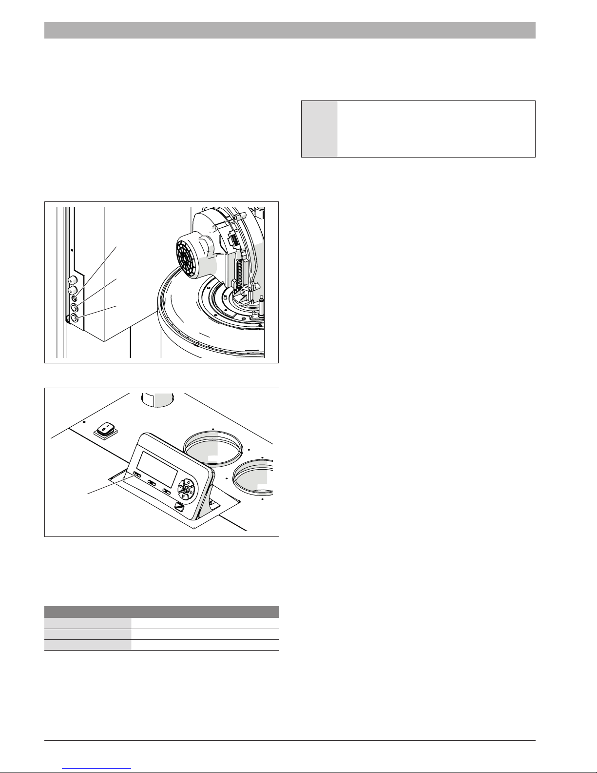
4.4.1 Low water cut off
A low water cut off (LWCO) is installed in the boiler, the manual reset
button is located on the front of the internal sliding wiring center.
To check the functionality of LWCO press the test button (the top button
shown in Fig. 10). The LED on the block will light and in the screen will
appear the error “MN: Low Water Cutoff Error”. At this point press the
reset button (the bottom button). The LED will turn off.
4.4.2 High limit safety switch
A high limit safety switch is installed in the boiler. To simulate a high limit
lockout at 208°F press the “MENU” and “OK” buttons simultaneously for
10 seconds. The control will display “MN: Max. Thermostat Lock Error”.
At this point press the reset button on the removable display to restart the
boiler.
LED
Test
Reset
4.4.4 Expansion tank
An expansion tank must be installed in the hydraulic system. The
expansion tank must be properly sized for the boiler and the system
volume, temperature and pressure.
WARNING: An undersized expansion tank will cause
leakage of water from the pressure relief valve and
introduce fresh water into the system. Excessive addition of
makeup water can cause corrosion of metallic components
and compromise the functionality of the boiler.
Refer to instructions provided by the manufacturer of the expansion tank
for details on its installation and sizing.
Fig. 10
Reset
Fig. 11
4.4.3 Pressure relief valve (PRV)
The boiler is supplied with a pressure relief valve (PRV). The relief
pressure for each valve for each model of the boiler is shown in the
following table:
Boiler model Relief Pressure
SSB255 30 psi (2.07 bar)
SSB399 30 psi (2.07 bar)
SSB512 75 psi (5.17 bar)
A 75psi pressure relief valve can be purchased separately and eld
installed.
The pressure relief valve (PRV) must be piped to a suitable drain to
prevent injury if the valve releases. Use a pipe of the same diameter of
the outlet of the valve
6720818454 (2016/02) US SSB
Installation | 17
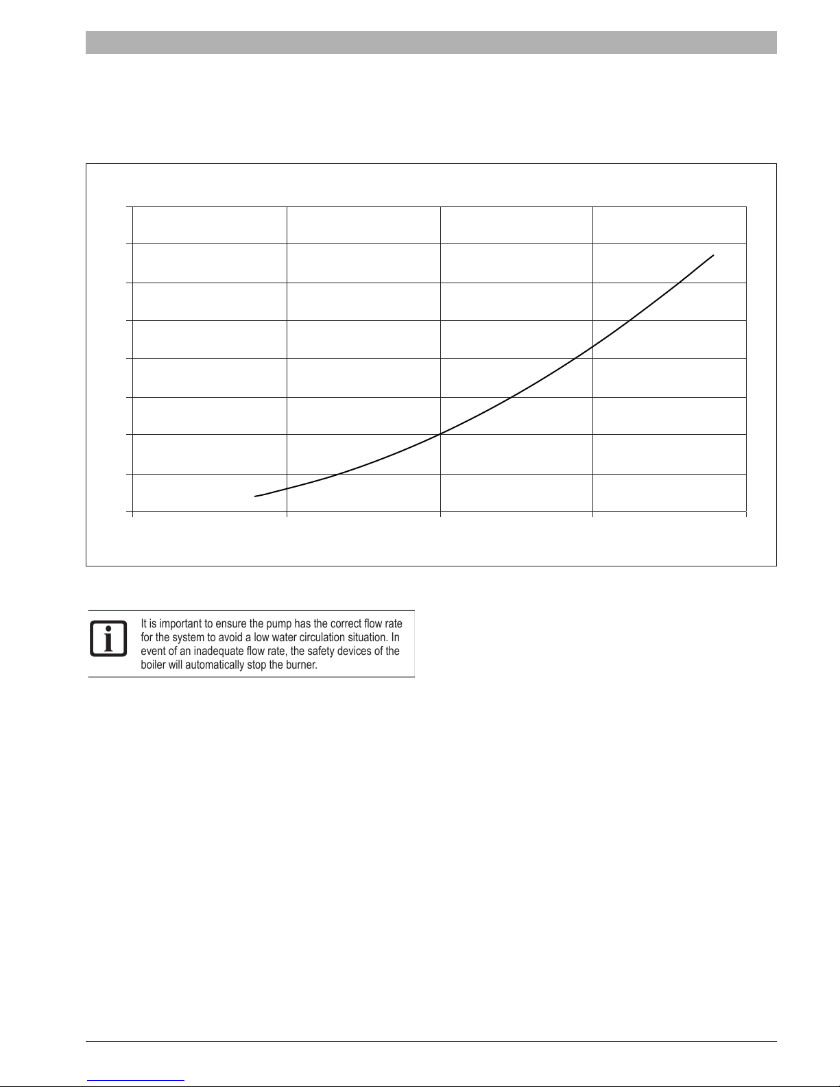
4.4.5 Pump
SSB boilers must be tted with a circulator pump. The graph in the following gure shows the pressure drop through the boiler circuit depending on the
ow rate.
SSB255
∆ p/ Feet of Head
8
7
6
5
4
3
2
1
0
0510 15 20
Fig. 12 SSB255 Pressure drop
It is important to ensure the pump has the correct ow rate
for the system to avoid a low water circulation situation. In
event of an inadequate ow rate, the safety devices of the
boiler will automatically stop the burner.
Flowrate / GPM
SSB 6720818454 (2016/02) US
18 | Installation
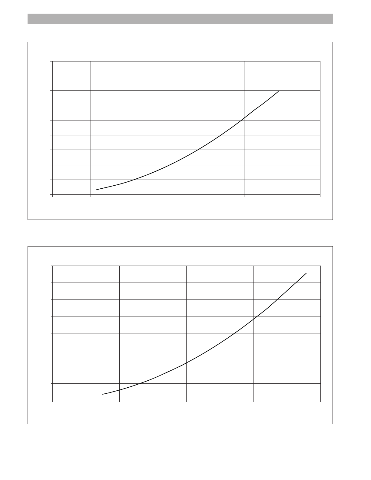
SSB399
∆ p/ Feet of Head
18
16
14
12
10
8
6
4
2
0
0510 15 20 25 30 35
Fig. 13 SSB399 Pressure drop
SSB512
∆ p/ Feet of Head
40
35
30
25
20
15
10
5
Flowrate / GPM
0
0510 15 20 25 30 35 40
Fig. 14 SSB512 Pressure drop
6720818454 (2016/02) US SSB
Flowrate / GPM
Installation | 19
H2O
1
H2O
2
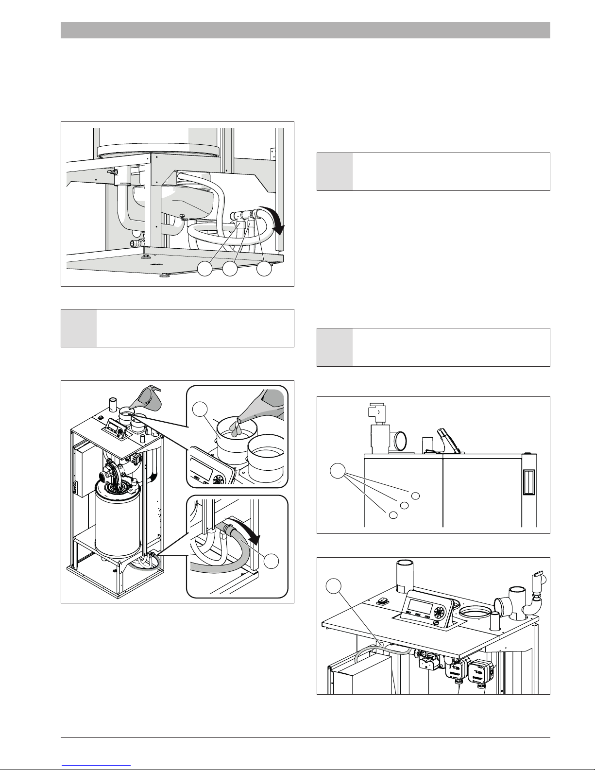
4.4.6 Condensate removal
The condensate water produced by the boiler during its normal operation
is collected by two plastic pipes (A and B) provided with the boiler and
connected with a plastic collector inside the case. A third tube (C) collects
the condensate output from the collector [Arrow is the direction of ow of
condensate].
A B C
Fig. 15
DANGER: The condensate pipe A and B, shown in Fig. 15,
must be lled with water or combustion gases will enter the
room with a risk of an excessive level of carbon monoxide.
To ll the condensate discharge add water from the vent (1) until you see
water come out of the condensate discharge pipe (2).
stream.
• Never use copper pipes or of other material not intended for the
specic purpose, because the action of condensate will cause a rapid
deterioration.
• Check that the condensate drain pipe is adequately sloping towards
the discharge point avoiding high points, which can inhibit the ow of
condensate.
• Install the condensate pipe in such a way so as to avoid the freezing
of the liquid.
NOTICE: Verify condensate disposal / neutralization is in
accordance with local, state and federal regulations.
A condensate removal pump is required if the boiler is below the drain.
When installing a condensate pump, select one approved for use with
condensing boilers and furnaces. The pump should have an overow
switch to prevent property damage from condensate leakage.
4.5 Electrical connection
4.5.1 Power supply cable connection
To connect the boiler to the electrical supply, as required by local, state
and federal codes, provide and install a service switch (15 amp is
recommended).
The power supply cable can be inserted into the boiler using one of the
six knock out holes (A) on the sides as shown in Fig. 17.
WARNING: All the electrical wiring must be secured by
appropriate strain reliefs.
To secure the supply cable inside of the boiler use the cable clamp shown
in position B shown in Fig. 18.
A
Fig. 17
B
Fig. 16
The condensate water shall be discharged at atmospheric pressure,
i.e. by dripping into a siphon-shaped container connected to the home
sewage system or suitable drain, and shall be neutralized prior to draining
per local codes.
The boiler is equipped with three holes (in the right, left and back side) to
carry the condensate out the condensate drain tube.
Install the condensate drain tube through the appropriate hole and be
sure to pitch away from the boiler.
• Do not reduce the diameter of the condensate drain pipe down
SSB 6720818454 (2016/02) US
Fig. 18
20 | Installation
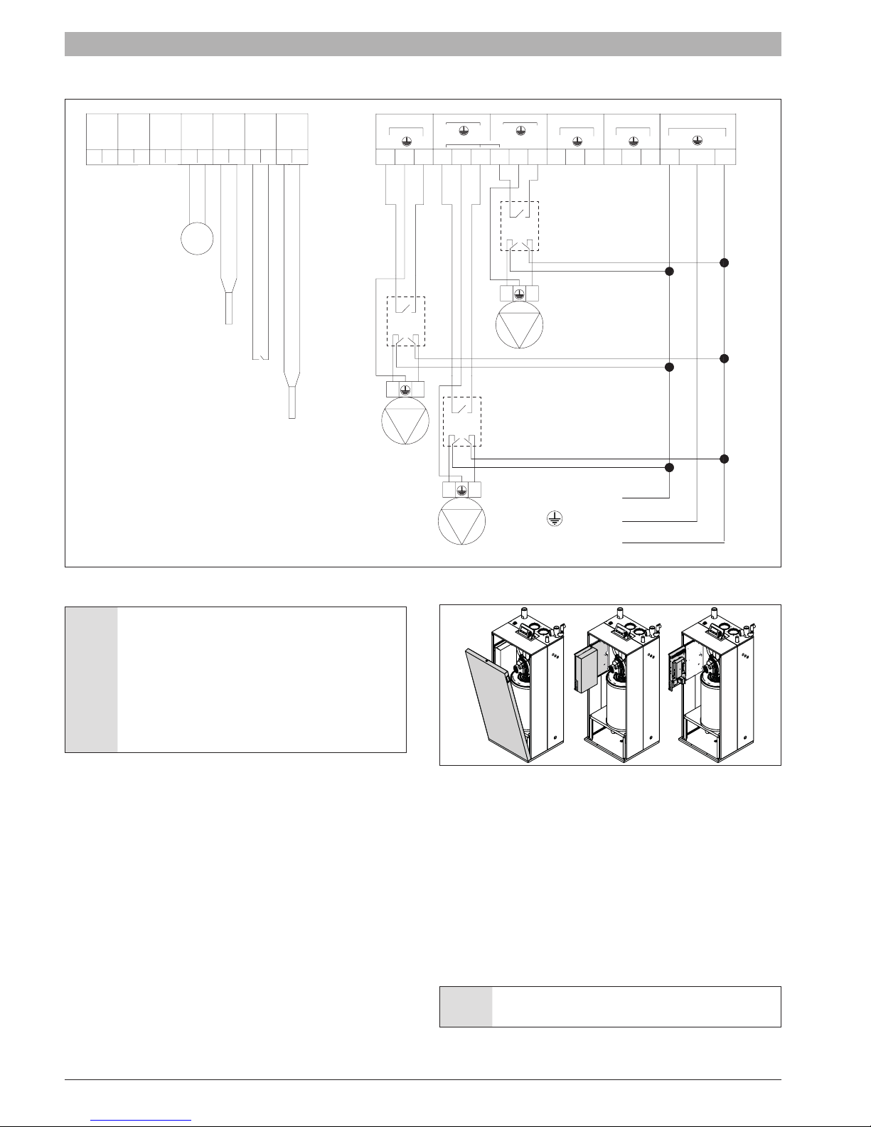
The general electrical connection is shown in the following diagram :
CASCADE
MOD
BUS
Switch
4567
Gas
LINK
123
Outdoor sensor
DHW tank sensor
or aquastat
Room thermostat
DHW Tank
Out
Door
89
Room
Thermostat
Sensor
10 11 12 13 14
Supply sensor
Supply
Sensor
Furnished
Relay (*)
and
Installed
by others
Boiler pump
System pump
Boiler
Pump
L
101102 103104 105106 107108 109
L
Pump CH
L
3 Way
N
N
Pump DHW
N
L
L
N
Relay (*)
Furnished and
Installed by others
L
N
120 V Neutral
N
L
110111 112
Alarm
N
L
113114 115
120 V Aux
Relay (*)
Furnished and
Installed by others
DHW tank pump
120 V Line
Ground
N
120 V Main in
L
116118117
(**)
N
Fig. 19
(*) NOTICE: The maximum amp load for each pump is 1 A
when 2 or 3 pumps are connected. For this reason, if the
power consumption of each pump is higher than 84 watt,
use a relay as shown in gure.
If just one pump is connected, the maximum amp load
of this single pump is 2 A. For this reason if the power
consumption of the pump is higher than 168 watt, use a
relay as shown in gure Fig. 19.
(**) NOTICE: line voltage.
4.5.2 Access to the electrical terminal strip
To have access to the internal terminal strip of the boiler follow the steps
below (see Fig. 20).
► Rotate the lock at the top on the front panel and remove the front
panel as shown.
► Slide out the electrical box and remove the two screw from the front.
► Remove the box cover to have access to the terminal strip.
Fig. 20
4.5.3 Room thermostat connection
Connect the thermostat to terminals 11 and 12 as shown in Fig. 19.
4.5.4 Outside temperature sensor
If outside temperature control is to be used, the outside probe needs
to be connected to terminals 7 and 8 as shown in Fig. 19. The outside
probe shall be installed on an outer wall, North or North/East, away from
windows, door, and ventilation grids. Never install the probe in a position
exposed to the sun.
The maximum length is 300’ (100 meter), if the cable length exceeds
32’ (10 meters) a shielded cable is required and shall be connected to
chassis ground.
6720818454 (2016/02) US SSB
NOTICE: All Sensors and low voltage wiring shall not be
routed in direct contact or near high voltage power.
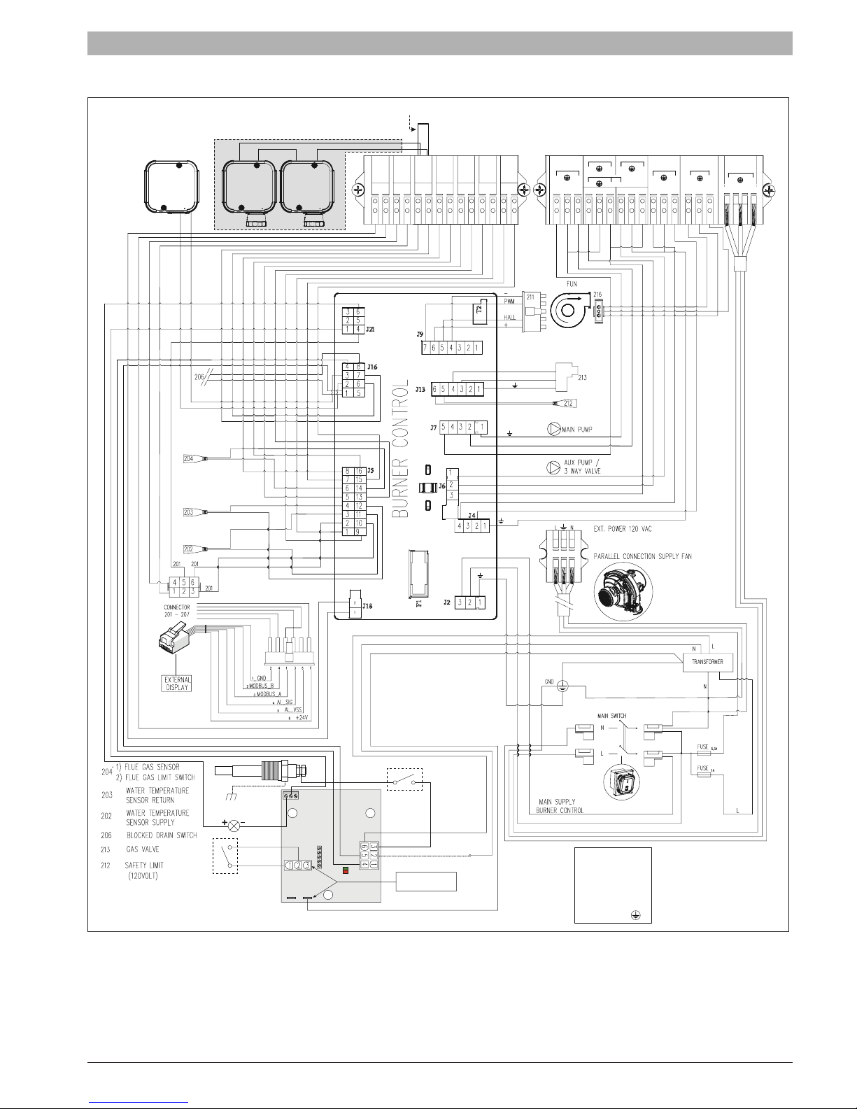
4.5.5 Electrical wiring diagram
FLUE
PRESSURE
SWITCH
PRESSURE
SWITCH
MAX
SSB512 ONLY
PRESSURE
SWITCH
MIN
SSB255 ONLY - SSB399 ONLY
CASCADE
LINK
12
MOD
BUS
34
GAS
SWITCH
OUT
DOOR
65
LOW VOLTAGE
IN / OUT
DHW
Supply
Room
Sensor
Tank
Ther-
Sensor
mostat
978
10
13
11 12
Installation | 21
HIGH VOLTAGE
OUT
PUMP CH
MAIN PUMP
14
L
103101102
PUMP DHW
NL NL
3 WAY
N
NL L
109107108
106104105
110
ALLARM
111
120 V AUX
NL
112
VOLTAGE
NL
116
115113114
HIGH
120 V
MAIN IN
L
117
N
118
w
w
blu
blu
blu
blu
blu
blu
brn
brn
brn
brn
blu
o
bl
blu
brn
blu
brn
24 V
bl
brn
blu
blu
brn
brn
brn
blu
w
brn
brn
blblugbrn
blubrn
bl
bl
blu
brn
brn
GND
bl
w
GND
w
N
GND
bl
bl
w
GND
w
bl
brn
w
113114115
L
bl w
bl
brn
w
bl
bl
w
w
bl w
24V
24V
CHASSIS
GROUND
(Via Boiler / Piping)
TEST
External Test Switch
(Normally Closed,
Opens to Test)
214
209
208
210
w
210
bl
210
209
bl
208
bl
bl
w
120V
AR1
w
w
214
208
w
209
bl
214
AR1
HIGH VOLTAGE
24 VAC HOT
PROBE
Manual Reset Switch
(Normally Closed,
Opens to Reset)
RESET
P
GND
AC COMMON
Alternate Chassis
Ground Connection
brn= CABLE BROWN
blu= CABLE BLUE
bl= CABLE BLACK
w= CABLE WHITE
o= CABLE ORANGE
g= CABLE GRAY
L= LINE
N= NEUTRAL
grn/yel = Ground
Fig. 21 Wiring diagram
SSB 6720818454 (2016/02) US
 Loading...