

Bosch SSB85, SSB160, SSB120 Service Manual
WARNING:
Improper installation, set-up, modication, operation or maintenance of
the heating system can cause personal injury and property damage.
Follow these instructions precisely.
If you require assistance or further information, contact a licensed
contractor / gas tter.
WARNING:
The operating instructions are part of the technical documents that
must be handed over to the owner or operator of the heating system.
Explain to the owner or operator how to use the heating system using
the operating instructions. Make sure that they are familiar with all
required information for the safe and proper operation of the heating
system.
These instructions are available in English and French.
Please keep these instructions for future reference.
Gas Condensing Stainless Steel Boiler
SSB BOILER
SSB85 | SSB120 | SSB160
Service Manual
6720866940 (2017/11) US

2 |
Contents
1 Key to symbols and safety instructions .............. 3
1.1 Key to symbols..................................3
1.2 Safety instructions ...............................3
1.3 General warning.................................3
Product description .......................... 4
2
2.1 Introduction.....................................4
2.2 Proper use .....................................4
2.3 Start/Stop cycle .................................5
Boiler components ........................... 6
3
Main components............................7
4
4.1 Burner head ....................................8
4.2 Heat exchanger .................................8
4.3 Combustion chamber .............................8
4.4 Ignition electrode ................................8
4.5 Low Water Cut Off (LWCO) ........................9
4.6 Supply and return temperature sensors ...............9
4.7 Manual reset high limit ............................9
4.8 Flue temperature sensor .........................10
4.9 Fan ..........................................10
4.10 Gas valve .....................................10
4.11 Venturi .......................................10
4.12 Condensate trap................................11
4.13 Flue pressure switch ............................11
4.14 Pressure relief valve.............................12
7 Commisioning ..............................21
7.1 First operation .................................21
7.2 Inlet Gas Pressure ..............................21
7.3 Switching from NG to LPG ........................21
7.4 CO
8
Maintenance schedule & procedures ................24
8.1 Gas Leak Inspection.............................24
8.2 Flue / Combustion air piping inspection ..............24
8.3 Checking for Wiring and connections................24
8.4 Burner Head Cleaning ...........................24
8.5 Cleaning the Heat Exchanger .....................26
8.6 Cleaning the Ignition Electrode ....................28
8.7 Inspection, replacement and features of supply, return
Electrical supply ............................29
9
9.1 Electrical supply wiring ...........................29
9.2 Access to the electrical terminal strip ................29
9.3 Main electrical supply ............................30
9.4 Room thermostat connection ......................30
9.5 DHW tank sensor connection......................30
9.6 Outdoor temperature sensor ......................30
9.7 Supplementary circulating pump relay ...............30
9.8 Electrical wiring diagram .........................31
9.9 Lockout errors list...............................32
9.10 Blocking errors list ..............................33
9.11 Errors not shown on display .......................35
2 Setting ...................................23
and flue NTC temperature sensors .................28
Control Panel (LCD Display) .....................13
5
5.1 LCD Display description ..........................13
5.2 Date and time setting ............................13
5.3 Setting Central Heating CH and DHW setpoint ........14
5.4 Boiler information ...............................14
5.5 Outdoor reset (Climatic compensation) ..............15
5.6 Parameters list .................................15
Parameters description ........................17
6
6.1 Central Heating (CH) ............................17
6.2 Domestic Hot Water .............................18
6.3 Pump mode and connections......................20
6720866940 (2017/11) US SSB
Spare parts ................................36
10
1 Key to symbols and safety instructions
1.1 Key to symbols
Warnings
Warnings in this document are identied by a warning
triangle printed against a grey background.
Keywords at the start of a warning indicate the type and
seriousness of the ensuing risk if measures to prevent the
risk are not taken.
The following keywords are dened and can be used in this document:
DANGER
•
result in death or serious injury.
WARNING
•
could result in death or serious injury.
CAUTION
•
could result in minor to moderate injury.
NOTICE
•
Important information
1.2 Safety instructions
Observe these instructions for your safety.
The burner and control must be correctly installed and adjusted to ensure
safe and economical operation of the gas boiler.
Read this installation and maintenance manual carefully and note the
details on the boiler nameplate before placing the boiler in operation.
Risk of fatal injury from explosion of ammable gases
If you smell gas there is a danger of explosion.
► Never work on gas lines unless you are licensed contractor / gas tter.
► Make sure that a licensed contractor / gas tter installs the boiler,
connects gas and vent, places the boiler in operation, connects the
electrical power, and maintains and repairs the boiler.
► No open ame! No smoking! Do not use lighters.
► Prevent spark formation. Do not operate electrical switches, including
telephones, plugs or door bells.
► Close main gas valve.
► Open doors and windows.
► Warn other occupants of the building, but do not use door bells.
► Call gas company from outside the building.
► If gas can be heard escaping, leave the building immediately, prevent
other people from entering, notify police and re departments from
outside the building
Risk to life from electrical shock.
► Disconnect the power supply to the boiler heating system before
conducting any work on it, e.g. turn off the heating system emergency
switch outside the boiler room.
► It is not sufcient just to turn off the control.
► Do not carry out electrical work unless you are qualied for this type
of work.
► Before servicing disconnect electrical power and lock out to prevent
accidental reconnection.
► Observe and follow the local, state and federal installation regulations.
indicates a hazardous situation which, if not avoided, will
indicates a hazardous situation which, if not avoided,
indicates a hazardous situation which, if not avoided,
is used to address practices not related to personal injury.
This symbol indicates important information where there is
no risk to people or property.
Key to symbols and safety instructions | 3
Risk of fatal injury from ue gas poisoning
Insufcient ventilation or combustion air availability may cause dangerous
ue gas leaks or formation.
► Make sure that inlets and outlets are not reduced in size or closed.
► If faults are not corrected immediately, the boiler must not be operated
until all faults have been corrected.
► Inform the system operator and/or owner of the fault and the danger
in writing.
► When working on the ue gas venting leakage of ue gases may
endanger the lives of people.
► Use only original parts when replacing vent system parts.
Risk to life by poisoning by spillage of ue gases
► If the blocked vent switch trips frequently the fault must be corrected
and proper operation of the blocked vent switch test must be
conducted.
Risk of fatal injury from neglecting your own safety in case of
emergency, such as with a re
► Never put yourself at risk. Your own safety must always take priority.
Fire danger due to ammable materials or liquids
► Make sure that there are no ammable materials or liquids in the
immediate vicinity of the boiler.
Installation and maintenance
► Observe all current standards and guidelines applicable to the
installation and operation of the boiler heating system as applicable in
your state or local jurisdiction.
► Clean and service the boiler system once a year. Check that the
complete heating system operates correctly.
► Immediately correct all faults to prevent system damage.
► Only use original Bosch spare parts. Losses caused by the use of
parts not supplied by Bosch are excluded from the Bosch warranty.
1.3 General warning
The installation of the unit must comply with all local, state and federal
applicable codes and regulation or, in absence of local codes in
conformity with ANSI Z223.1 / NFPA 54 for gas-red boilers and ANSI/
NFPA 58 for LP gas-red boilers. The equipment shall be installed in
accordance with the current Installation Code for Gas Burning Appliances
and Equipment, CSA B149.1 Canada. Authorities having jurisdiction and
local inspection agencies must be informed before installation starts.
Where required by local, state and federal regulations, the system must
comply with the American Society of Mechanical Engineers Safety Code
for Controls and Safety Devices for Automatically Fired Boilers (ASME
CSD-1). The hot water distribution system must comply with all applicable
codes and regulations. When replacing an existing boiler, it is important to
check the condition of the entire hot water distribution system to ensure
safe operation. Valves external to the boiler must be tted with T-handles
and condensate piping must be installed in accordance with the State
Plumbing Code.
SSB 6720866940 (2017/11) US

4 | Product description
NOTICE:
► This boiler must be installed by a licensed contractor/ gas tter.
Failure to do so shall void the product warranty.
► The boiler is intended only for the use for which it was specically
designed and built. Bosch is hereby excluded from any liability for
damages caused to persons, animals or property resulting from
installation errors, improper adjustment, maintenance or use.
► In order to ensure safety and correct operation, the installation shall
always take place in full compliance with the applicable Codes and
following with the instructions provided by the manufacturer, and must
always be carried out by a licensed contractor / gas tter only.
► The equipment must be installed in appropriate place and in
combination with appropriate systems as specied by code.
► The unit may be exposed to temperatures between 5° F (-15°C) and
150°F (65°C) in its original packaging. Do not expose the unit to
weather without the protection of the original packaging until the boiler
has been properly installed. Until then there is no frost protection for
the boiler.
► After removing the packaging check the integrity and completeness of
delivery and in case of non-compliance, contact your dealer.
► If there is a water loss, disconnect the boiler from the main power
supply, close the water supply and immediately call technical
assistance or installer/local contractor.
► Periodically check that the condensate drain is free from obstruction.
► Periodically check the system pressure. System pressure should be
checked when the system is in standby mode and no call for heat is
present.
► Maintenance is mandatory and shall be carried out at least once a
year.
► This manual shall be read carefully, in order to install and operate the
boiler appropriately, and safely.
► Boiler installations, settings and service should only be performed by
experienced licensed contractor / gas tter. End Users should only
make adjustments with the assistance of a licensed contractor / gas
tter.
► Any maintenance operation or service before disconnecting the boiler
from the main power supply is forbidden.
► Do not remove or modify safety equipment.
► Do not pull or twist the electrical wires, from the boiler, even if the
device is disconnected from the main power supply.
► Do not obstruct or reduce the ventilation openings.
► Do not put the unit outdoors.
► Do not leave any combustibles or containers of ammable substances
in the room where the boiler is installed.
► Do not dump the packing material. Keep out of reach of children the
packing material because it can be potentially dangerous. It must be
disposed of as required by law.
► The opening of metal casing of the device and removing of the cover
are prohibited to the end user. Any service on the boiler must be
carried out by qualied technician.
► Dispose of equipment in accordance with local codes, and in a
environmentally responsible manner.
2 Product description
2.1 Introduction
• The gas-red condensing SSB boilers are designed to be used in
central heating systems. Any other use is prohibited.
• This boiler can be connected to an indirect storage tank for the
production of domestic hot water.
• There are several options for venting including single pipe, two pipe
and concentric. See section “4.7 Venting and air piping system” for
details.
• The quality of the system water is very important. Poor water quality
can damage heating systems and boilers due to scale formation and
corrosion (see water quality section).
• The boilers can also function directly with any hydronic emitter.
When installing the boiler and system connections, the installer must
consider the total head loss and ow rates in order to adequately size
piping and circulator pumps.
• The SSB boiler can be connected to a room thermostat.
• An outdoor air temperature sensor must also be connected to the
boiler for an outdoor reset supply temperature control for increased
fuel efciency and comfort.
2.2 Proper use
► The SSB Boilers are designed for residential, and light commercial
applications.
► The appliance may only be installed in closed loop hot water central
heating systems.
► Any other purpose is considered improper use. Any resulting damage
is excluded from the manufacturer’s warranty.
► In some heating applications like pool, spa snow melt or process
water heating a heat exchanger must to be installed.
6720866940 (2017/11) US SSB
2.3 Start/Stop cycle
Product description | 5
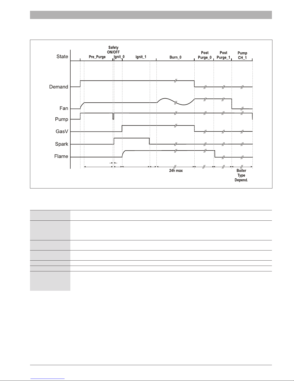
Fig. 1 Burner ignition cycle diagram
False ame detection
Re-ignition
Intermittent operation
Flame establishing time
Flame out too late If after Max_Post_Purge_0 time ame is still detected a lockout follows.
Safety relay test In Safety ON/OFF state the correct working of the safety relay is proven.
Demand
Tab. 1
If ame is detected at the end of the pre-spark period (Ignit_0) a lockout error occurs (This lockout has a maximum of 3 auto
resets).
If at the end of the safety period no ame is detected the control will go to post-purge to remove the unburned gas. After this a
re-ignition attempt is started following the same cycle.
The number of re-ignition attempts is limited to Max_Ignit_Trials after which a lockout occurs.
The burner can only be ON continuously for a period of 24 hours.
After this the burner is switched OFF and a restart sequence follows.
Sparking stops Spark_Before_End_Of_Safety_Period seconds before the end of the Ignit_1 period to allow for ionization
detection.
Once the ignition sequence is started it will be nished*. Even if the demand is taken away during the ignition sequence the
sequence up to the burn state is ended.
If during Burn_0 state the demand is taken away, a Post_Purge_Period follows at Post_Purge_Speed speed.
SSB 6720866940 (2017/11) US
6 | Boiler components
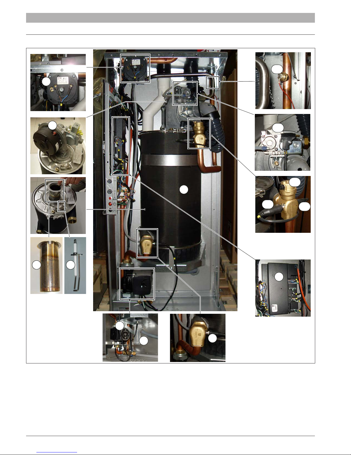
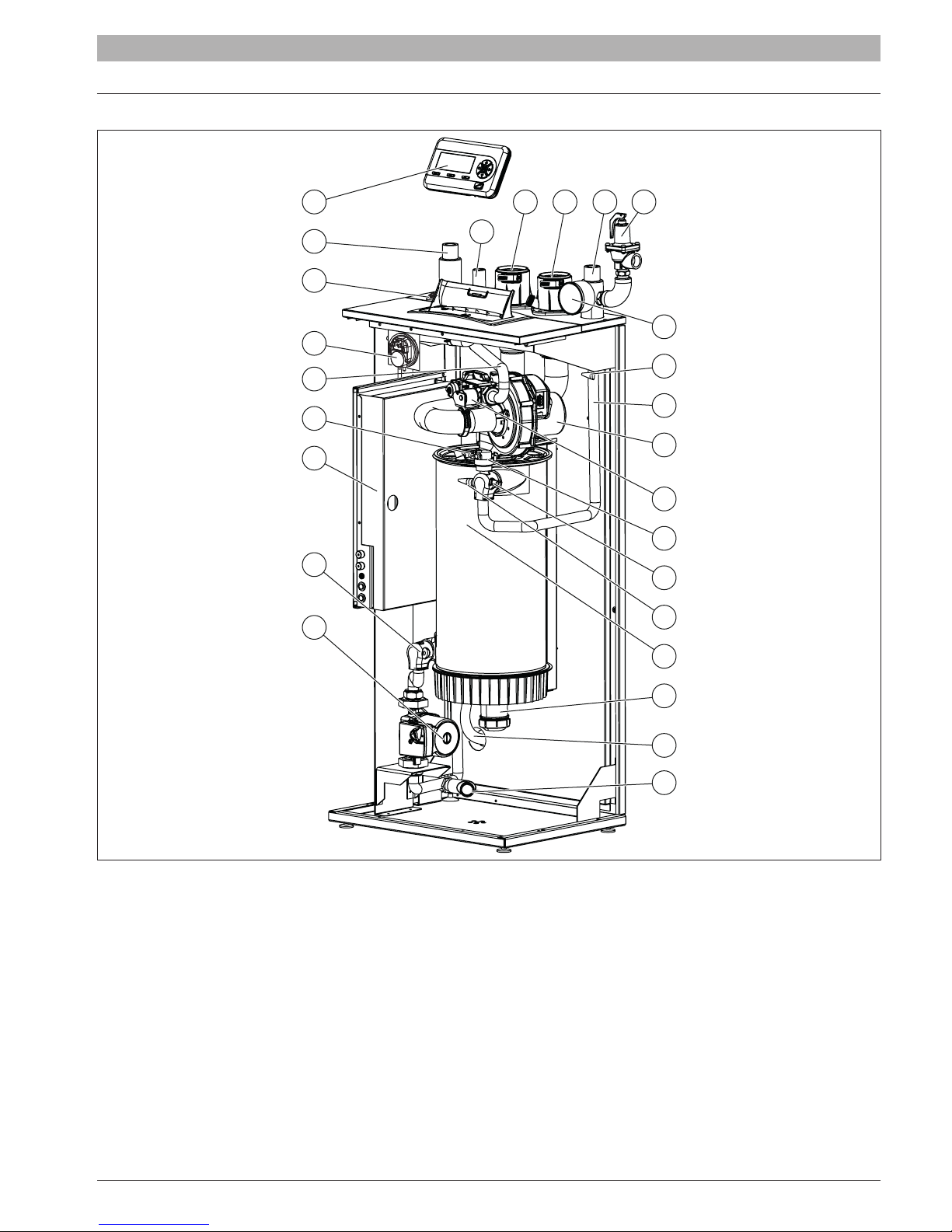
3 Boiler components
1
14
2
3 4
13
10
8
11
12
9
5
Fig. 2 Boiler components
[1] Pressure differential switch
[2] Fan
[3] Burner head
[4] Spark electrode
[5] Circulation pump
[6] Condensate trap
[7] Return temperature probe
6720866940 (2017/11) US SSB
6
[8] Heat exchanger
[9] Main controller
[10] Automatic air vent
[11] High limit temp. safety switch
[12] Supply temperature probe
[13] Gas valve
[14] Low water cut off probe
7
4 Main components
Main components | 7
24
2
1
25
23
22
21
20
19
7654
3
8
9
10
11
12
13
14
15
Fig. 3 Main components
[1] Main power switch
[2] System return
[3] Gas inlet
[4] Flue exhaust
[5] Intake air
[6] System supply
[7] Pressure Relief Valve
[8] Tridicator
[9] Low water cut off probe
[10] Heat exchanger supply pipe
[11] Fan
[12] Gas valve
[13] Automatic air vent
[14] Supply temperature probe
16
17
26
18
[15] High limit temp. safety switch
[16] Heat exchanger
[17] Condensate trap
[18] Low point drain valve
[19] Circulation pump
[20] Return temperature probe
[21] Wiring Control Panel
[22] Spark electrode
[23] Gas pipe
[24] Removable display
[25] Pressure differential switch
[26] Condensate discharge pipe
SSB 6720866940 (2017/11) US
8 | Main components
Ignition electrode
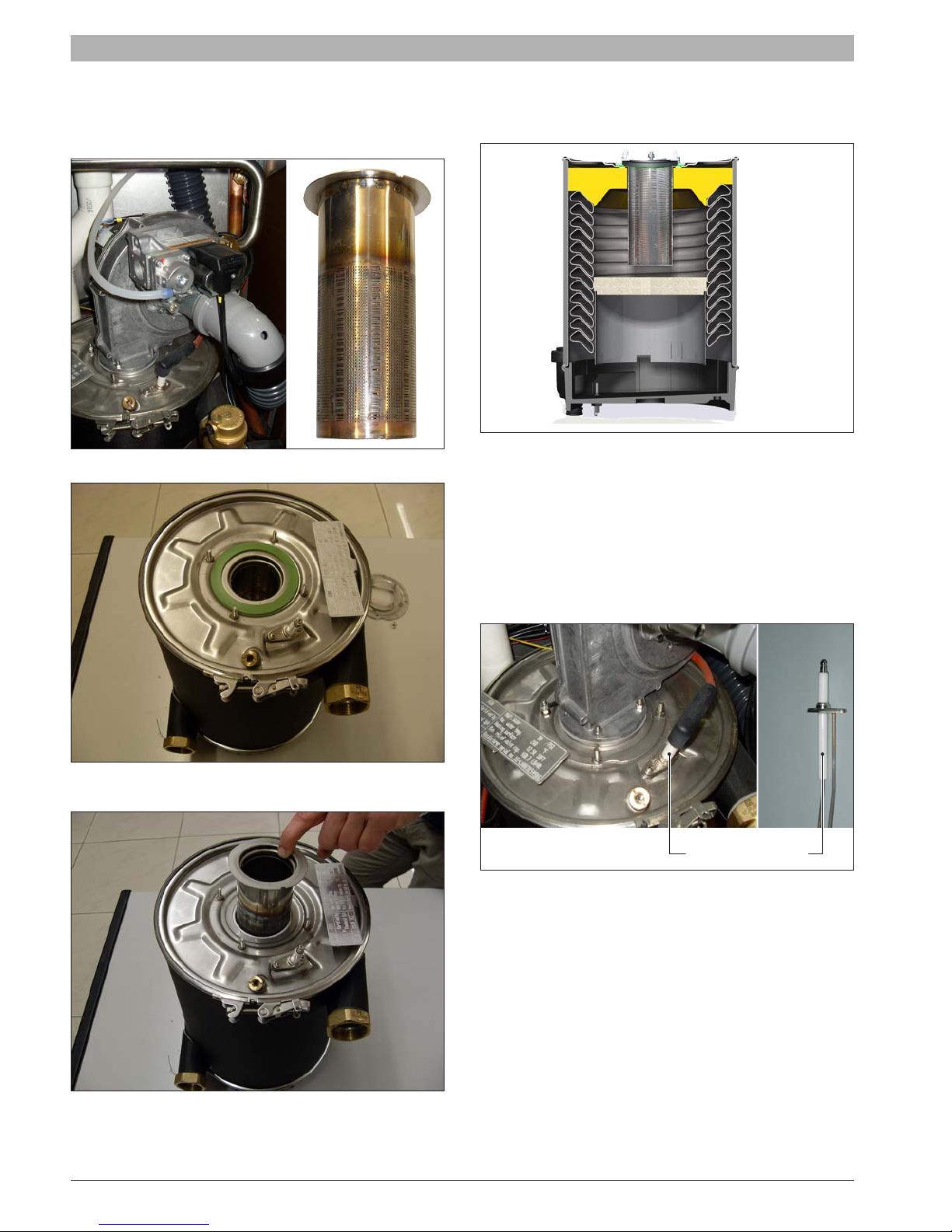
4.1 Burner head
The burner head (Fig. 4) is made of stainless steel, it supports a micro
premix ame. The burner can be accessed by removing the larger four
fan motor mounting nuts. (Fig. 5 - Fig. 6).
Fig. 4 Burner head
4.2 Heat exchanger
The heat exchanger (Fig. 7) is a single coil design made of stainless
steel.
Fig. 7 Heat exchanger & Burner cross-sectional view
4.3 Combustion chamber
The cylindrical combustion chamber (Fig. 7) has a top and bottom steel
ring-bands that are removable for heat exchanger servicing.
4.4 Ignition electrode
The ignition electrode (Fig. 8) is a component inserted in the burner
ange on the head of heat exchanger. It has 2 functions: ignition and
ame detection.
Fig. 5 Heat exchanger (fan motor removed - note location of green
Fig. 6 Burner head
6720866940 (2017/11) US SSB
burner gasket)
Fig. 8 Ignition electrode
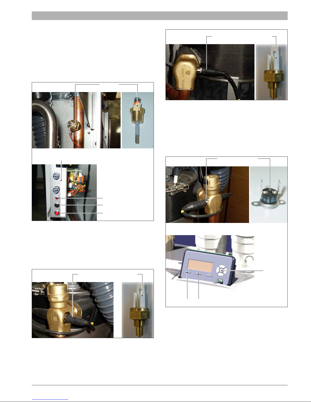
4.5 Low Water Cut Off (LWCO)
Sensor
Supply temperature sensor
Return temperature sensor
Safety thermostat
Reset Menu
The Low Water Cut off (LWCO) is installed on the supply pipe, at the
highest position available. Using a dedicated wet sensor it checks the
minimum level of water inside the boiler by way of an electrical signal
ground. The electronic control board is located in the primary electrical
enclosure. It includes a self-test and a manual reset button (Fig. 9) To
check the functionality of LWCO, press the test button. The LED turns ON
and the boiler will display the error “Low water cut off”. At this point press
the red reset button located just below the Test button. The LED will turn
off and the error should clear from the boiler display.
Electronic Low Water Cut Off
Main components | 9
Fig. 11 Return temperature probes
4.7 Manual reset high limit
The safety thermostat (Fig. 12) is located near the supply sensor. It’s an
automatic reset type set at 194°F. Above this temperature the contact
opens removing power to the gas valve. The display shows the “overtemperature” error code requiring manual reset. To test the functionality
of the sensor hold for 10 sec both “Ok” & “Menu” buttons on display. It will
appear the “High limit T max” error message. At this point press the reset
button to restart the boiler.
Led
Test
Reset
Fig. 9 FLow Water Cut Off (LWCO)
4.6 Supply and return temperature sensors
The supply (Fig. 10) and return (Fig. 11) temperature sensors are
immersion type NTC’s rated 10KΩ at 25°C(77°F).
See Tab. 12 for resistance values for NTC sensor.
The supply sensor is located at the outlet of the heat exchanger the
return temperature sensor is located at the inlet of the heat exchanger.
!
Fig. 10 Supply temperature sensors
OK
Fig. 12 Manual reset High Limit Safety Thermostat
SSB 6720866940 (2017/11) US
10 | Main components
Flue temperature sensor
1 2
3
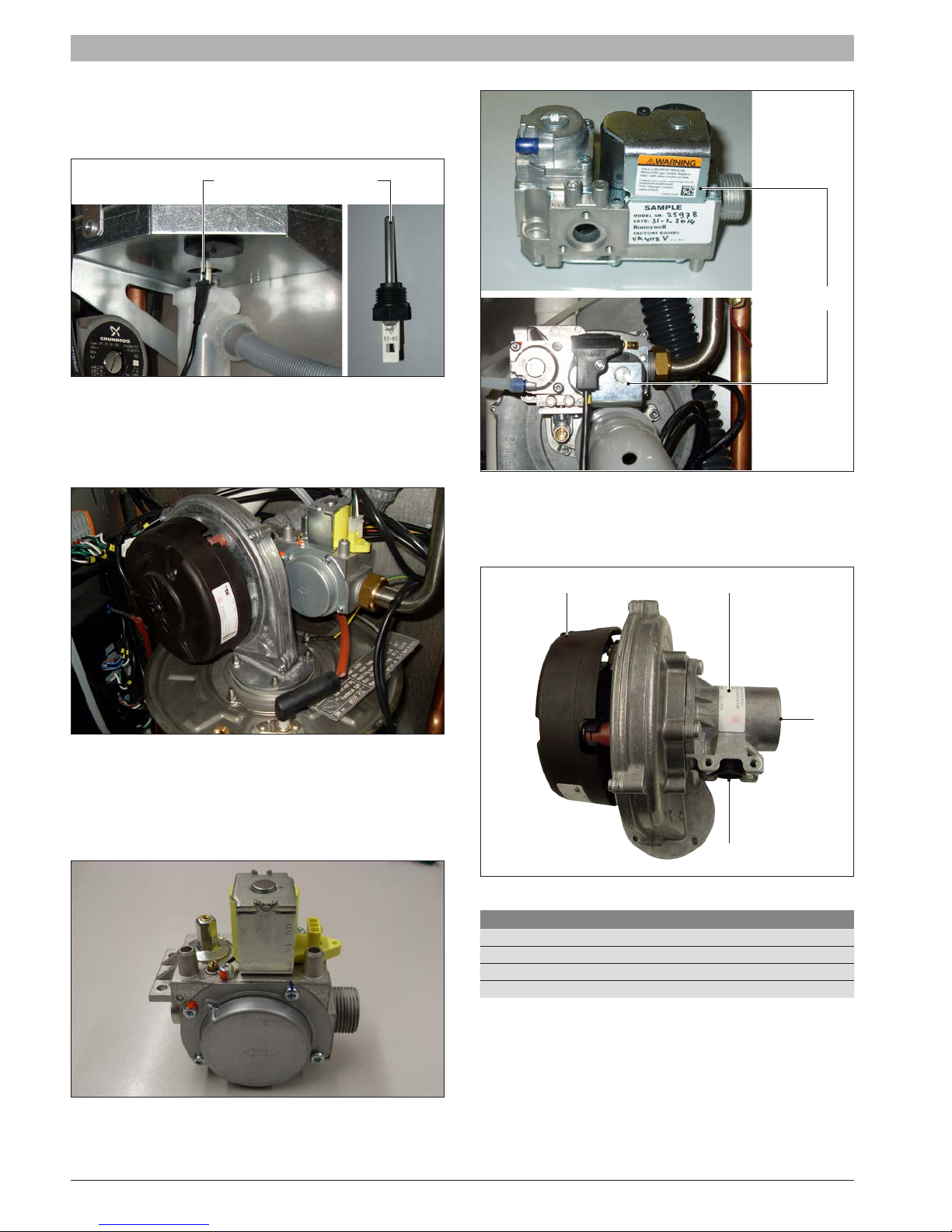
4.8 Flue temperature sensor
The ue temperature sensor (Fig. 13) is located on the bottom of the heat
exchanger. It’s an immersion type NTC sensor rated at 10KΩ @ 77°F. It
prevents ue gas temperatures in excess of 100°C (212°F).
Fig. 13 Flue temperature sensor
4.9 Fan
The fan (Fig. 14) is located on the top of combustion chamber and
fastened to the burner head. The fan has an integrated PWM speed
control.
gas valve
Fig. 16 Gas valve SSB160
Fig. 14 Fan
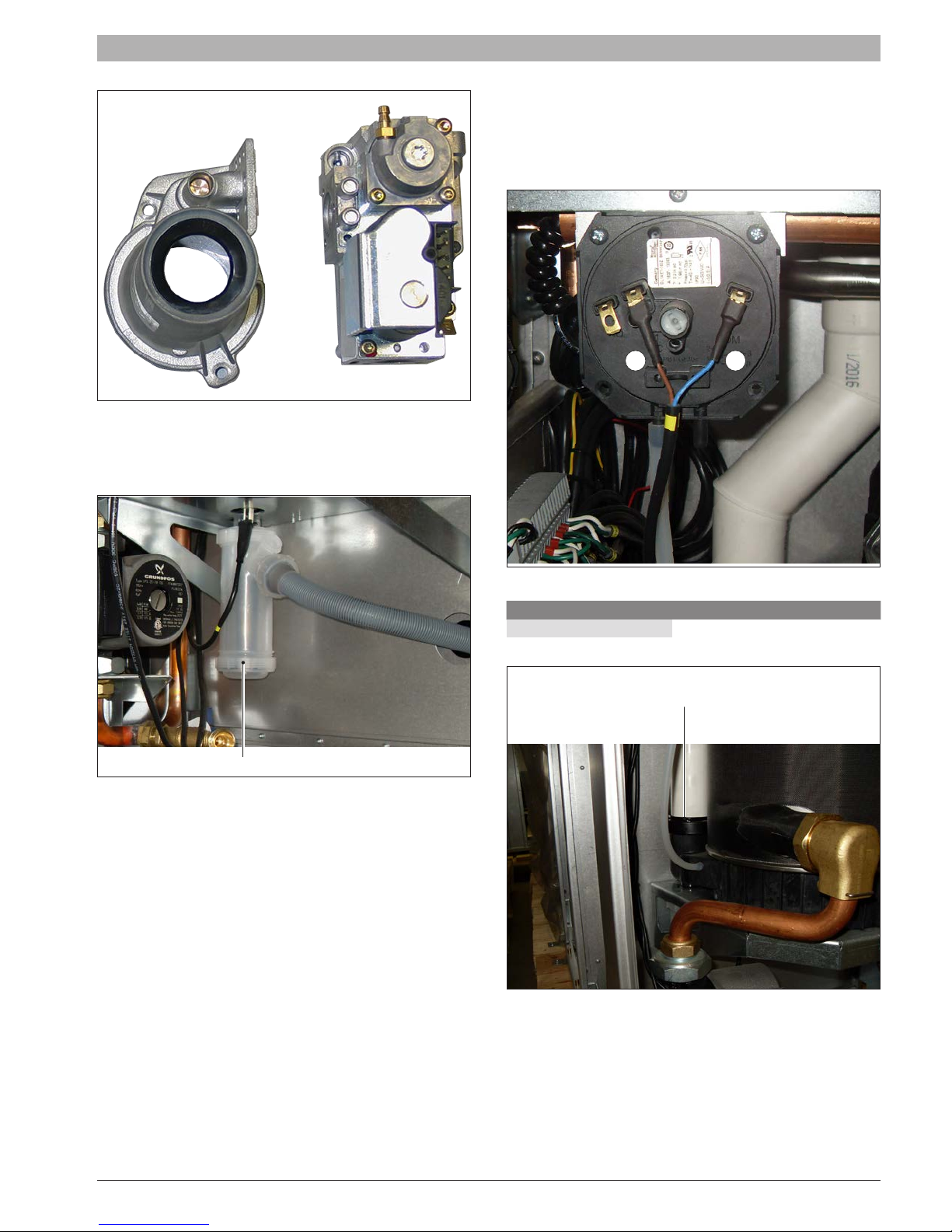
4.10 Gas valve
The proportional gas valve (Fig. 15 - Fig. 16) is located above the fan and
it’s connected to the Venturi. The gas valve has 2 safety solenoid valves.
The gas valve regulates the air/fuel ratio on the basis of combustion air
delivery (the air/fuel ratio is 1:1).
4.11 Venturi
The Venturi (Fig. 17 - Fig. 18) is integrated in the fan for all models. Its
function is to mix the air and fuel.
4
Fig. 17 Venturi SSB85 - SSB120
Component
[1] Fan
[2] Venturi
[3] Air inlet
[4] Gas inlet
Tab. 2 Venturi SSB85 - SSB120
Fig. 15 Gas valve SSB85 - SSB120
6720866940 (2017/11) US SSB
Main components | 11
Condensate trap
Connection on the bottom
4.13 Flue pressure switch
Flue pressure switch is a safety device designed to turn off the burner in
case of block vent (for example due to obstruction of condensate drain).
The silicon pipe is connected on one end to the “+” port of pressure
switch (Fig. 20), and on the other end to the bottom of the heat exchanger
(Fig. 21).
Fig. 18 Venturi SSB160
4.12 Condensate trap
The trap (Fig. 19) drains condensate discharged from the heat exchanger
and ue pipe.
Fig. 19 Condensate trap
+
Fig. 20 Flue pressure switch
Inch W.C. mbar
1.4 3,5
Tab. 3 Flue gas pressure switch setpoint value
of heat exchanger
-
SSB 6720866940 (2017/11) US
Fig. 21 Flue pressure switch
12 | Main components
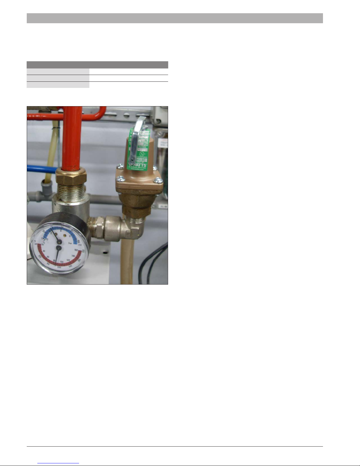
4.14 Pressure relief valve
The boiler is protected by a relief valve against overpressure. The 3/4”
discharge outlet must be piped per local code requirements.
Boiler model Pressure value
SSB85 30 psi (2,07 bar)
SSB120 30 psi (2,07 bar)
SSB160 30 psi (2,07 bar)
Tab. 4 Max. Setpoint values of relief valve
Fig. 22 Pressure relief valve (pipe connection from boiler supply to relief
6720866940 (2017/11) US SSB
valve is eld supplied and does not come with the boiler).
Control Panel (LCD Display) | 13
1 2 3 4 5
78
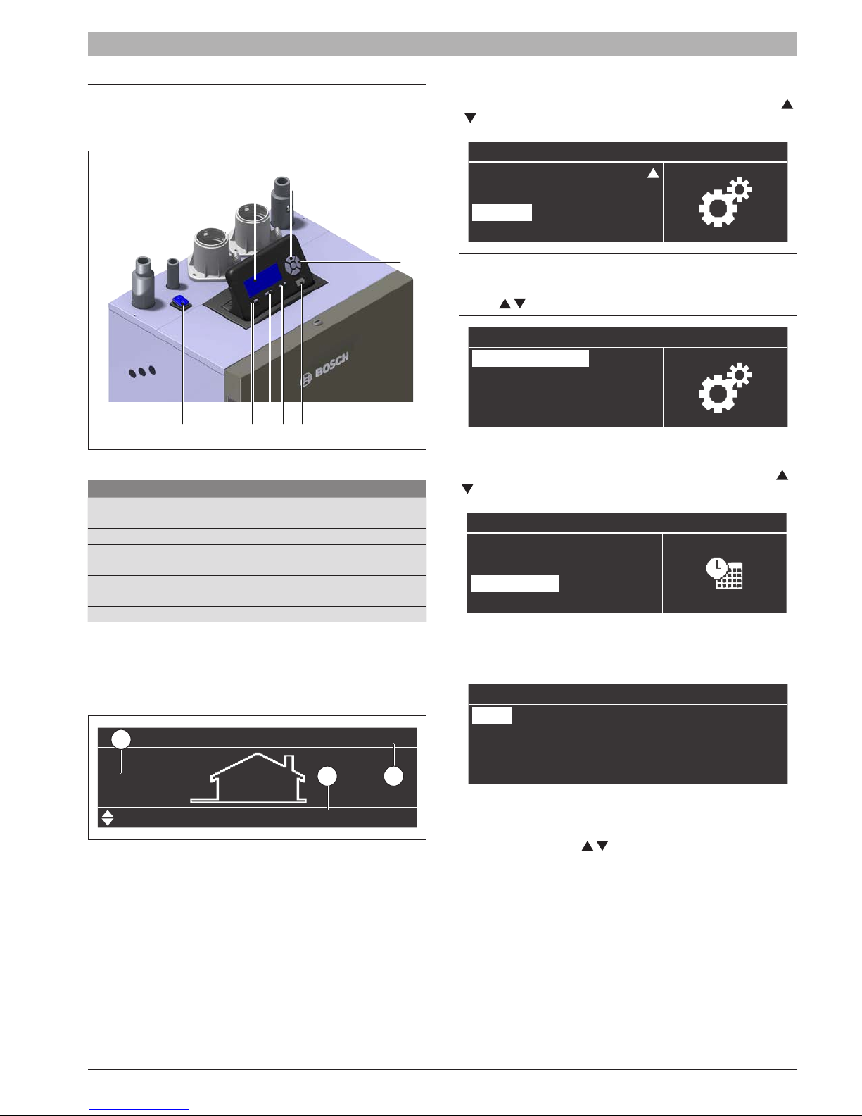
5 Control Panel (LCD Display)
The homepage on the display shows the basic status of the boiler.
Fig. 23 Control Pannel
No.
[1] ON/OFF button
[2] Reset button
[3] Menu button
[4] ESC button
[5] PC service connection
[6] OK button
[7] Up/Down/Right/Left button
[8] Dispaly
Tab. 5 Control panel description
5.1 LCD Display description
Switch the appliance ON using the ON/OFF switch. The display will
appear as follow:
1
04:29 pm
70.0°F
5.2 Date and time setting
Press the “menu” button and select “Settings” using the arrow buttons
/
to select “Settings”.
Menu
Domestic Hot Water
Information
Settings
System Test
6
Fig. 25
Press the “OK” button and select “General Settings” using the arrow
buttons (
/ ).
Settings
General Settings
Boiler Settings
Fig. 26
Press the “OK” button, select “Date & Time” using the arrow buttons (
/ ).
General Settings
Language
Unit type
Date & Time
Other settings
Fig. 27
Press “OK”. The display will show the following information:
Date & Time
Date: Sun 10/25/2015
Time:
03:02 pm
Time Zone Settings
32
Display Settings
DHW Setpoint
Fig. 24
On the left of the display is shown the external temperature (1) is shown
(if the outdoor sensor is connected). On the right the set setpoint (2)
value is shown. The top right corner shows the time (3).
SSB 6720866940 (2017/11) US
120.0°F
Fig. 28
Press the “OK” to highlight the values. Values can be modied using the
“UP/”DOWN” keys button “
When nished press “OK” to save the changes.
/ ”.
14 | Control Panel (LCD Display)
Entering the “Time Zone Settings” menu it is possible to set the time zone
parameter as shown on the following gure:
Time Zone Settings
Time Zone Correction UTC +00.00
Daylight Savings Time
Fig. 29
To modify the visualization of the date and time value, entering in the
“Display Settings” menu it is possible to change the following features:
Disabled
Display Settings
Time Notation 24h
Date Order
Day Of Month
Month
Fig. 30
DMY
2Digits
2Digits
Display Settings
Year 4Digits
Date Separation Character
Day Of Week
Seconds
Fig. 31
“-”
Short Text
No
Fig. 33
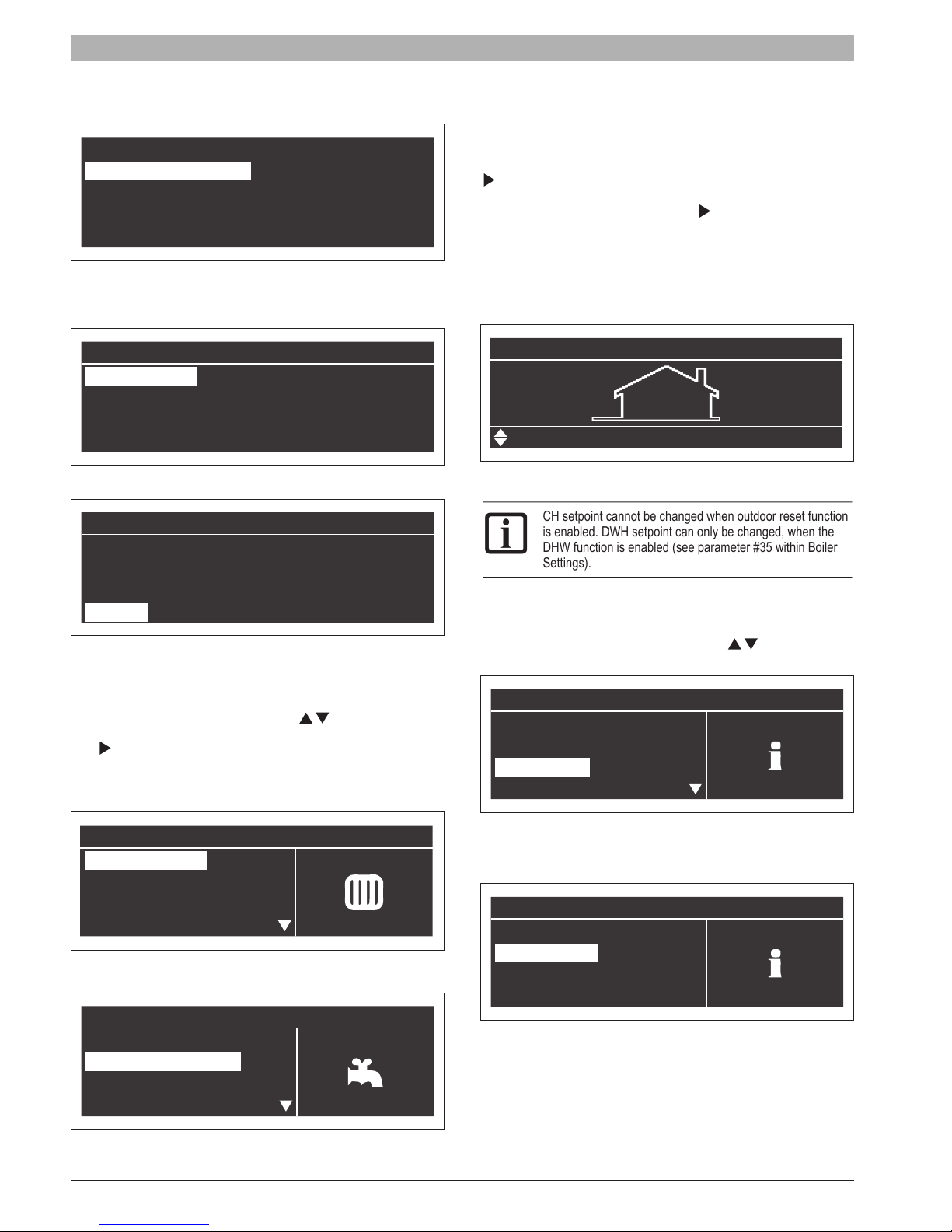
CH and the DHW setpoint can be edit directly from the homepage of the
display.
When the text on the bottom left side is “CH Setpoint” press the right
” button. The value shown in the bottom right side will be highlighted;
“
using the “UP/DOWN” keys it is possible to change the value. Once
assigned the desired value press the right “
be stored.
To change the DHW setpoint press the “UP/DOWN” buttons. The text in
the bottom left side will change to “DHW Setpoint”. Now it is possible to
change the DHW setpoint using the same procedure which we described
before.
” button. The new value will
04:29 pm
70.0°F
DHW Setpoint
Fig. 34
CH setpoint cannot be changed when outdoor reset function
is enabled. DWH setpoint can only be changed, when the
DHW function is enabled (see parameter #35 within Boiler
Settings).
5.4 Boiler information
To access the main information about the boiler press “menu” button and
select “Information” using the “UP/DOWN” keys “
120.0°F
/ ”.
5.3 Setting Central Heating CH and DHW setpoint
To change the Central Heating (CH) and DHW setpoint through menu
screen, press “menu” select use UP/DOWN “
the parameter and select by pressing the “OK”. Once selected, use the
right “
” arrow key to highlight the temperature and use the UP/DOWN
arrow to change selected temperature. Press “OK” to conrm/save new
temperature.
/ ” arrows to choose
Menu
Central Heating
Domestic Hot Water
Information
Settings
Fig. 32
Menu
Central Heating
Domestic Hot Water
Information
Settings
Menu
Central Heating
Domestic Hot Water
Information
Settings
Fig. 35
Press “OK” and display will show:
Information
Software Versions
Boiler Status
Fig. 36
6720866940 (2017/11) US SSB
Control Panel (LCD Display) | 15
Press “OK” and the display will show the following information:
• Supply Temperature
• Return Temperature
• DHW Temperature [Sensor must be connected to show a value. If not,
the default value will appear]
• Outside Temperature
• Flue Temperature [Sensor must be connected to show a value. If not,
the default value of 14°F will appear]
• System Temperature [Sensor must be connected to show a value. If
not, the default value will appear]
• Fan Speed
• Ionization
• State
• Error
The display shows four lines at a time:
Boiler Status
Flow Temperature 115.0 °F
Return Temperature
110.0 °F
DHW Temperature 111.0 °F
Outside Temperature 50.0 °F
Fig. 37
To scroll the screen use the “UP/DOWN” keys “
5.5 Outdoor reset (Climatic compensation)
To set the outdoor reset curve enter “Central Heating (CH)” menu and
press “OK”.
The display will appear as follow:
/ ”.
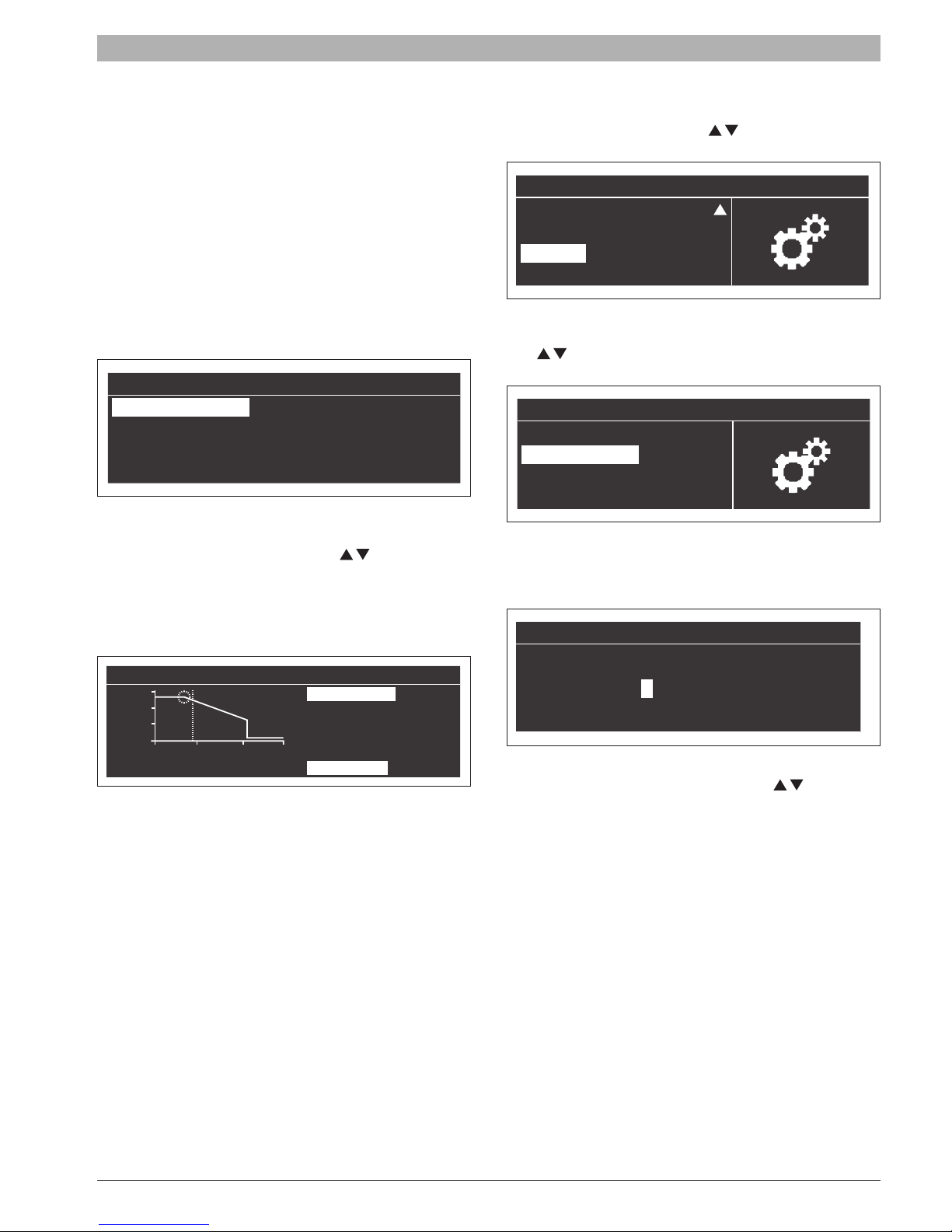
5.6 Parameters list
To have access to the parameter list press “menu” button and select
“Settings” using the “UP/DOWN” keys “
/ ”.
Menu
Domestic Hot Water
Information
Settings
System Test
Fig. 39
Press the “OK” button and select “Boiler Settings” using the “UP/DOWN”
keys “
/ ”.
Settings
General Settings
Boiler Settings
Fig. 40
Press the “OK” button. At this point a password is requested [Password
is required for boiler settings only]:
Password
Outdoor reset
194
32
5 95
Setp. [°F]
Fig. 38
“Des. Supply T” and “Des. Outd T” will be highlighted, to change either
value press “OK”:
• Use UP/DOWN arrows to change the “Des. Supply T”. Use the LEFT/
RIGHT arrows to change the “Des Outd. T”
• Press “OK” to save changes
• Use the LEFT/RIGHT arrows to select the other values
Repeat steps to make additional changes
Once set the parameters press “ESC” to exit the menu.
T_Outside [°F]
Des. Supply T. 180°F
Bas. Supply T. 104°F
WW Shutdown 70°F
Bas. Outd. T. 70°F
Des. Outd. T. 25°F
0 * * *
Fig. 41
Enter one digit at a time using the UP/DOWN” keys “
decrease the value. When the value is correct then press “OK”.
In the system there is a password for the two levels:
• Level 1 USER: no password needed (0000)
• Level 2 INSTALLER: password “0300”
/ ” to increase/
SSB 6720866940 (2017/11) US
 Loading...