

Bosch SSB1000 SA, SSB800 SA, SSB1000 TL User Manual
WARNING:
Improper installation, set-up, modication, operation or maintenance of
the heating system can cause personal injury and property damage.
Follow these instructions precisely.
If you require assistance or further information, contact a trained and
certied installer.
WARNING:
The operating instructions are part of the technical documents that
must be handed over to the owner or operator of the heating system.
Explain to the owner or operator how to use the heating system using
the operating instructions. Make sure that they are familiar with all
required information for the safe and proper operation of the heating
system.
These instructions are available in English and French.
Please keep these instructions for future reference.
BUDERUS SSB BOILER
CONTROL SYSTEM MANUAL
SSB800 SA | SSB1000 SA | SSB1000 TL
Installation and Service Instructions for Contractors
6720892984 (2019/02) US

2 |
Contents
1 Key to symbols and safety instructions .............. 4
1.1 Key to symbols ..................................4
1.2 Safety instructions ...............................4
1.3 General warning .................................4
STAND-ALONE BOILER (Burners Cascade) - SYSTEM
2
ARCHITECTURE
2.1 General........................................6
2.2 905TS Control Systemn ...........................6
2.2.1 Modbus connection 905PB and 905TS ...............6
2.2.2 Setpoints on touch screen .........................7
2.3 2 Burners Cascade with Touchscreen and Building
2.4 Dipswitch setting for 2 Burners Cascade ..............8
2.5 Additional device specifications .....................8
BURNERS cascade ...........................9
3
3.1 Burner cascade communication setup ................9
3.2 Setting the burner address (Rev. 4.0.905.15250)........9
3.2.1 E2prom address selection through e2prom setting ......9
3.2.2 E2prom address selection through dip-switch input......9
3.2.3 Communication with LabVision PC software ..........10
3.3 Cascade – Heating only (Rev. 4.0.905.15250).........10
3.3.1 Cascade – domestic hot water .....................12
3.3.2 Cascade – DHW priority (Rev. 3.0.0.12377) ..........12
3.3.3 Limitation of the MAX power for DHW (Rev.
3.3.4 Cascade – start/stop sequence (Rev. 3.0.0.12315) .....13
3.3.5 Cascade – power balance mode (Rev. 4.0.905.15906) ..15
3.3.6 Cascade – burner rotation (Rev. 4.0.905.x) . . . . . . . . . . .17
3.3.7 Cascade – error handling .........................17
Service display .............................18
4
4.1 General.......................................18
4.1.1 Introduction....................................18
4.1.2 General information .............................18
4.1.3 Display functions ...............................18
4.1.4 Display icons ..................................18
4.2 Screens ......................................19
4.2.1 Splash screen (Rev 1.1.0.13425)...................19
4.2.2 Entering the menu ..............................19
4.2.3 Protected menu items ...........................19
4.2.4 DAir Sequence .................................20
4.2.5 Language settings ..............................20
4.3 Menu Structure.................................22
Main control ...............................26
5
5.1 Ignition cycle (Rev 3.0.0.0)........................26
5.2 Control functions ...............................26
5.2.1 Demand for central heating (Rev 3.0.0.0) ............26
5.2.2 Demand for Domestic Hot Water (Rev 3.0.0.0) ........31
............................. 6
Management System (BMS) .......................7
4.0.905.16570) .................................12
5.3 Safety and system function .......................34
5.3.1 Flame detection (Rev 3.0.0.0) .....................34
5.3.2 Ionization jumper (Rev 3.0.0.0) ....................34
5.3.3 Flame recovery (Rev 3.0.0.0)......................34
5.3.4 Overheat detection (safety limit) (Rev 3.0.0.0).........34
5.3.5 Sensor availability (Rev 3.0.0.0)....................34
5.3.6 Pump start every 24 hours (Rev 3.0.0.0) .............35
5.3.7 Frost protection (Rev 3.0.0.0)......................35
5.3.8 Flue temperature protection (Rev 3.0.0.0) ............36
5.3.9 Input configuration 900MN (Rev 4.0.905.16712) .......36
5.3.10 Output configuration 900MN (Rev 4.0.905.16712) .....36
5.3.11 Heat exchanger protection: max differential (Rev 3.0.0.0) 37
5.3.12 Appliance selection (Rev 3.0.0.0)...................37
5.3.13 Anti-legionella protection (Rev 3.0.0.0) ..............37
5.3.14 De-Air sequence (Rev 3.0.0.0).....................38
5.3.15 Low water cut off (Rev 3.0.0.0).....................39
5.3.16 Heat exchanger protection (Rev 3.0.0.0) .............39
Boiler cascade..............................41
6
6.1 Extended 4x2 boiler/burner cascade with Touch Screen
and Building Management System (BMS) ............41
6.2 Compensation for secondary manifold temperature on
single boiler ...................................42
6.3 Set Switches for all cascade boards ................42
6.3.1 Power off all the boards ..........................42
6.3.2 Set AL Power switch S1 and Dip switch for 905MN
Managing of Boiler X ............................42
6.3.3 Set AL Power switch S1 and Dip switch for 905MN
Dependent boards ..............................42
6.4 Set the Modules and Boiler Cascade Settings ........42
6.4.1 Cascade of Modules: Set the address for all the
modules Boards ...............................42
6.4.2 Cascade of Modules: Set Number of expected Modules
(to do only in the managing of Modules) .............42
6.4.3 Cascade of Boilers: Set Boiler Address for all the
Managing boards ...............................42
6.4.4 Cascade of Boilers: Set Number of expected Boiler (to
do only in the managing of Boiler) ..................42
System test................................43
7
7.1 System test (Rev 3.0.0.0).........................43
7.1.1 System test for cascade burners with air-damper
functionality ...................................43
7.2 Physical high limit test mode. (100°C +/- 5°C).........43
7.2.1 Starting the test ................................43
7.2.2 Running the test ................................43
7.2.3 Stopping the test ...............................44
7.2.4 Monitoring of attempts ...........................44
7.2.5 Limitations ....................................44
7.3 LWCO Error evaluated at Boiler level................44
7.4 System test in cascades with air damper ............44
Service reminder ............................45
8
8.1 Service Reminder...............................45
6720892984 (2019/02) US SSB

8.1.1 Service Reminder...............................45
8.1.2 Service Overdue logging .........................45
8.1.3 Service Reminder implementations .................45
8.1.4 Resetting the Service Reminder....................45
8.1.5 Menu’s and Parameters ..........................45
| 3
Appendix A - Connection diagram
Appendix B - Maximum load on outputs
Appendix C - System parameters
Appendix D - Control System Technical Specifications
Appendix E - NTC sensor curve selection (Rev 3.0.0.0)
Appendix F - 5 Error table (Rev. 4.0.905.17114)
Appendix G - PID: Proportional-Integral-Derivative controller
Appendix H - Cascade parameter
Appendix I - Connector description for 905mn1x (120vac version)
Appendix J - PB Connectors Description
Appendix K - Modbus
............................67
....................46
.................48
.....................49
.......54
.......55
.............55
...59
.....................62
. . . . . . . . . . . . . . . .65
63
Appendix L - Safety timing
Appendix M - Building Management System (BMS) Registers
Specifications
.........................73
..............................75
SSB 6720892984 (2019/02) US
4 | Key to symbols and safety instructions
1 Key to symbols and safety instructions
1.1 Key to symbols
Warnings
Warnings in this document are identied by a warning
triangle printed against a grey background.
Keywords at the start of a warning indicate the type and
seriousness of the ensuing risk if measures to prevent the
risk are not taken.
The following keywords are dened and can be used in this document:
DANGER
•
result in death or serious injury.
WARNING
•
could result in death or serious injury.
CAUTION
•
could result in minor to moderate injury.
NOTICE
•
Important information
1.2 Safety instructions
Observe these instructions for your safety.
The burner and control must be correctly installed and adjusted to ensure
safe and economical operation of the gas boiler.
Read this installation and maintenance manual carefully and note the
details on the boiler nameplate before placing the boiler in operation.
Risk of fatal injury from explosion of ammable gases
If you smell gas there is a danger of explosion.
► Never work on gas lines unless you are licensed contractor / gas tter.
► Make sure that a licensed contractor / gas tter installs the boiler,
connects gas and vent, places the boiler in operation, connects the
electrical power, and maintains and repairs the boiler.
► No open ame! No smoking! Do not use lighters.
► Prevent spark formation. Do not operate electrical switches, including
telephones, plugs or door bells.
► Close main gas valve.
► Open doors and windows.
► Warn other occupants of the building, but do not use door bells.
► Call gas company from outside the building.
► If gas can be heard escaping, leave the building immediately, prevent
other people from entering, notify police and re departments from
outside the building
Risk to life from electrical shock.
► Disconnect the power supply to the boiler heating system before
conducting any work on it, e.g. turn off the heating system emergency
switch outside the boiler room.
► It is not sufcient just to turn off the control.
► Do not carry out electrical work unless you are qualied for this type
of work.
► Before servicing disconnect electrical power and lock out to prevent
indicates a hazardous situation which, if not avoided, will
indicates a hazardous situation which, if not avoided,
indicates a hazardous situation which, if not avoided,
is used to address practices not related to personal injury.
This symbol indicates important information where there is
no risk to people or property.
accidental reconnection.
► Observe and follow the local, state and federal installation regulations.
Risk of fatal injury from ue gas poisoning
Insufcient ventilation or combustion air availability may cause dangerous
ue gas leaks or formation.
► Make sure that inlets and outlets are not reduced in size or closed.
► If faults are not corrected immediately, the boiler must not be operated
until all faults have been corrected.
► Inform the system operator and/or owner of the fault and the danger
in writing.
When working on the ue gas venting equipment or vent damper leakage
of ue gases may endanger the lives of people.
► Carefully observe proper operation of the vent damper. Do not start up
the boiler unless the vent damper is operating properly.
► Use only original parts when replacing parts.
► When replacing the vent damper, install the new one in the specied
position.
Risk to life by poisoning by spillage of ue gases
► If the blocked vent switch trips frequently the fault must be corrected
and proper operation of the blocked vent switch test must be
conducted.
Risk to life by poisoning by leakage of ue gases
► Make sure that the boiler is not equipped with a thermally controlled
ue gas vent damper after the open draft hood.
Risk of fatal injury from neglecting your own safety in case of
emergency, such as with a re
► Never put yourself at risk. Your own safety must always take priority.
Fire danger due to ammable materials or liquids
► Make sure that there are no ammable materials or liquids in the
immediate vicinity of the boiler.
► Maintain a minimum distance of 15 inches from the boiler.
Installation and maintenance
► Observe all current standards and guidelines applicable to the
installation and operation of the boiler heating system as applicable in
your state or local jurisdiction.
► Clean and service the boiler system once a year. Check that the
complete heating system operates correctly.
► Immediately correct all faults to prevent system damage.
► Only use original Bosch spare parts. Losses caused by the use of
parts not supplied by Bosch are excluded from the Bosch warranty.
1.3 General warning
The installation must conform to the requirements of the authority having
jurisdiction or, in the absence of such requirements, to the latest edition
of the National Fuel Gas Code, ANSI Z223.1./NFPA 54. In Canada,
installation must be in accordance with the requirements of CAN/CSA
B149.1, Natural Gas and Propane Installation Code.
Where required by local, state and federal regulations, the system must
comply with the American Society of Mechanical Engineers Safety Code
for Controls and Safety Devices for Automatically Fired Boilers (ASME
CSD-1).
The hot water distribution system must comply with all applicable codes
and regulations. When replacing an existing boiler, it is important to check
the condition of the entire hot water distribution system to ensure safe
operation.
Valves external to the boiler must be tted with T-handles and condensate
piping must be installed in accordance with the State Plumbing Code.
6720892984 (2019/02) US SSB

NOTICE:
► This boiler must be installed by a licensed contractor/ gas tter.
Failure to do so shall void the product warranty.
► The boiler is intended only for the use for which it was specically
designed and built. Bosch is hereby excluded from any liability for
damages caused to persons, animals or property resulting from
installation errors, improper adjustment, maintenance or use.
► In order to ensure safety and correct operation, the installation shall
always take place in full compliance with the applicable codes and
following with the instructions provided by the manufacturer, and must
always be carried out by a licensed contractor / gas tter only.
► The equipment must be installed in appropriate place and in
combination with appropriate systems as specied by code.
► The unit may be exposed to temperatures between 5 deg F (-15°C)
and 150 deg F (65°C) in its original packaging. Do not expose the
unit to weather without the protection of the original packaging until
the boiler has been properly installed. Until then there is no frost
protection for the boiler.
► After removing the packaging check the integrity and completeness of
delivery and in case of non-compliance, contact your dealer.
► If there is a water loss, disconnect the boiler from the main power
supply, close the water supply and immediately call technical
assistance or installer/local contractor.
► Periodically check that the condensate drain is free from obstruction.
► Periodically check the system pressure. System pressure should be
checked when the system is in standby mode and no call for heat is
present.
► Maintenance is mandatory and shall be carried out at least once a
year.
► This manual shall be read carefully, in order to install and operate the
boiler appropriately, and safely.
► Boiler installations, settings and service should only be performed by
experienced licensed contractor / gas tter. End Users should only
make adjustments with the assistance of a licensed contractor / gas
tter.
► Any maintenance operation or service before disconnecting the boiler
from the main power supply is forbidden.
► Do not remove or modify safety equipment.
► Do not pull or twist the electrical wires, from the boiler, even if the
device is disconnected from the main power supply.
► Do not obstruct or reduce the ventilation openings.
► Do not install the unit outdoors.
► Do not leave any combustibles or containers of ammable substances
in the room where the boiler is installed.
► Keep packing material out of reach of children as it can be potentially
dangerous. It must be disposed of as required by law.
► The opening of metal casing of the device and removing of the cover
are prohibited to the end user. Any service on the boiler must be
carried out by authorized personal.
► It’s prohibited to dispose the product as domestic waste. The
separate disposal of a household appliance avoids possible negative
consequences for the environment and human health deriving from
inappropriate disposal and allows to recover the materials it is made
of in order to achieve signicant savings in energy and resources.
Key to symbols and safety instructions | 5
SSB 6720892984 (2019/02) US
6 | STAND-ALONE BOILER (Burners Cascade) - SYSTEM ARCHITECTURE
2 STAND-ALONE BOILER (Burners Cascade) - SYSTEM ARCHITECTURE
2.1 General
The 900 series burner controls are designed to function as a standalone control unit for intermittent operation on heating appliances with a premix
(modulating) burner and a pneumatic air-gas system.
This specication is suitable for the following version:
PN: 900MN 900MN type for Commercial units
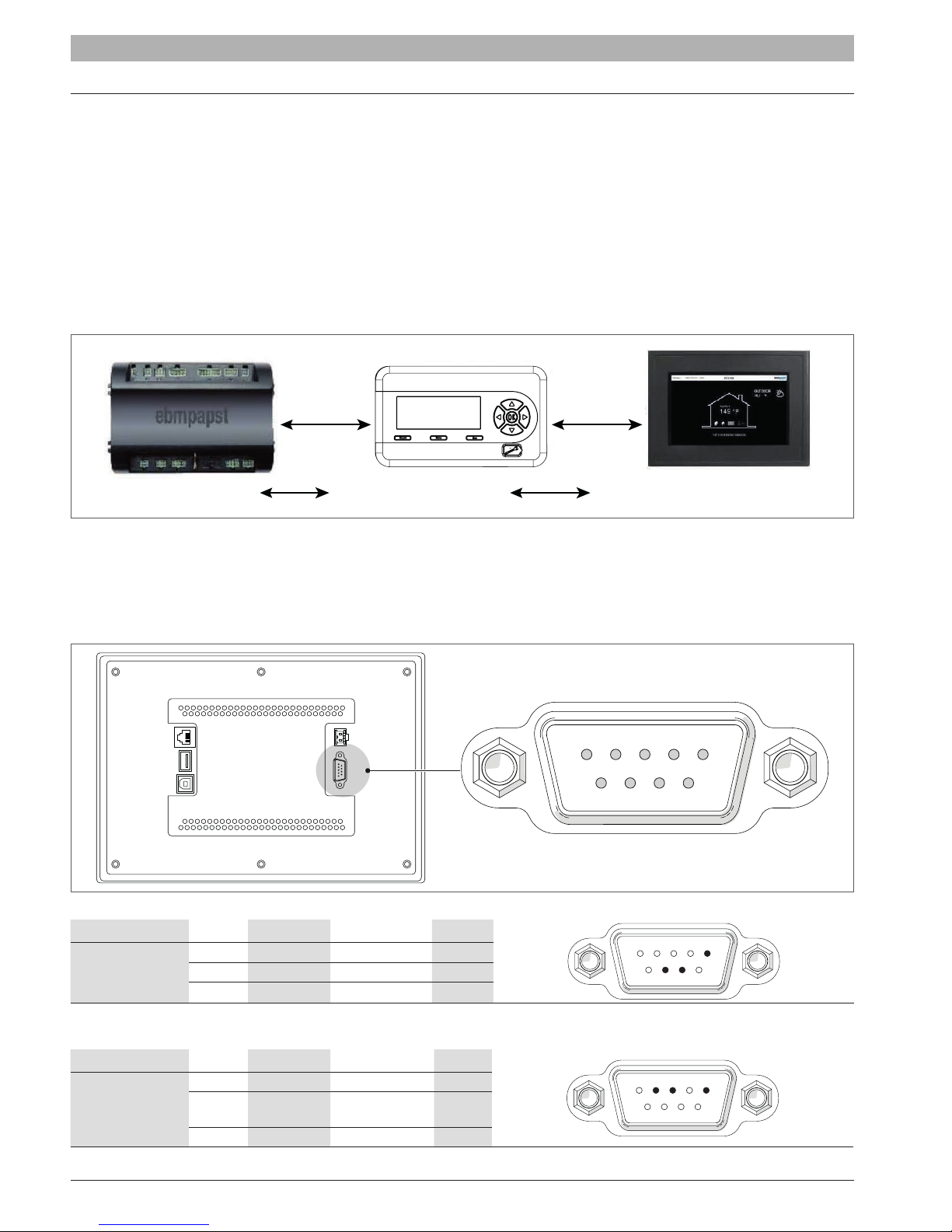
2.2 905TS Control Systemn
The following scheme shows the communication protocols the 905 Modules use to communicate with each other:
AL-BUS MODBUS
905MN control (J6)
905PB Display (J25)
905TS Touch Screen (COM2)
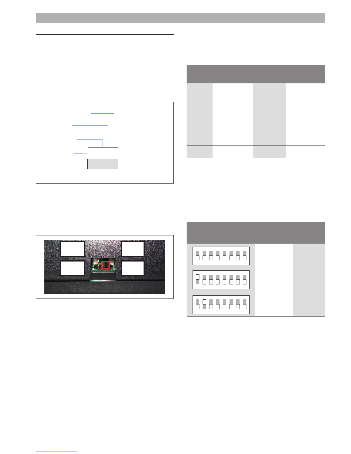
2.2.1 Modbus connection 905PB and 905TS
The 905TS has a port on the backside called ‘COM’, which is used to communicate with the 905PB display by MODBUS. The following illustration shows
the location of the COM port (backside 905TS) and pin-numbering:
LANUSB1USB2
+ -
24VDC
COM
1 2 3 4 5
6 7 8 9
Primary connection to 905PB:
Communication Pin Function Connect to
COM2
(Master)
5 GND 905 PB (J25-1)
7 RS 485 + 905 PB (J25-3)
8 RS 485 - 905 PB (J25-2)
1 2 3 4 5
6 7 8 9
Optional secondary interface:
Communication Pin Function Connect to
2 RS 232 RXD External Adapter RS 485
COM1
(Slave)
3 RS 232 TXD External Adapter RS 485
5 GND
6720892984 (2019/02) US SSB
1 2 3 4 5
6 7 8 9
STAND-ALONE BOILER (Burners Cascade) - SYSTEM ARCHITECTURE | 7
2.2.2 Setpoints on touch screen
The following table describes the setpoints that are shown on ver 2.d or higher:
CH mode
Cascade screen – System setpoint
Cascade system supply setpoint
Boiler screen – Boiler Setpoint Cascade
boiler supply setpoint
Module screen – Module Setpoint
Burner supply setpoint
No demand CH Mode X setpoint Frost Protection Setpoint Frost Protection setpoint
Frost CH Mode X setpoint Frost Protection Setpoint Frost Protection setpoint
0 Parameter CH setpoint
1 Calculated outdoor setpoint
2 Calculated outdoor setpoint
3 Calculated outdoor setpoint
Cascade system supply setpoint
+
increase calculated by the boiler cascade
controller
Cascade boiler supply setpoint
+
increase calculated by the burner/module
cascade controller
4 0-10V input setpoint
Cascade boiler supply setpoint
Emergency
Cascade
See above Cascade System Emergency Setpoint
increase calculated by the burner/module
+
cascade controller
Emergency
Boiler
See above Boiler Emergency Setpoint Boiler Emergency Setpoint
The following table describes how the setpoint is limited in a cascade system:
E2_Ch_Max_Setpoint 90°C / 194°F = Absolute maximum setpoint
Controller maximum setpoint = 90°C / 194°F E2_CH_Reset_Curve_Boiler_Maximum
CH Control range
Controller minimum setpoint = 30°C / 86°F E2_CH_Reset_Curve_Boiler_Minimum
E2_Ch_Min_Setpoint 20°C / 68°F = Absolute minimum setpoint
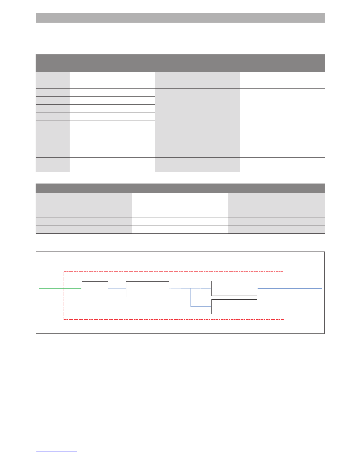
2.3 2 Burners Cascade with Touchscreen and Building Management System (BMS)
Single boiler containing up to 2 modules/burners
BMS bus
RS485
RS232
Touch Screen
Module / burner 1
Module / burner 2
Cascade bus
SSB 6720892984 (2019/02) US
8 | STAND-ALONE BOILER (Burners Cascade) - SYSTEM ARCHITECTURE
1
ON DIP
2 3 4 5 6 7 8
1
ON DIP
2 3 4 5 6 7 8
1
ON DIP
2 3 4 5 6 7 8
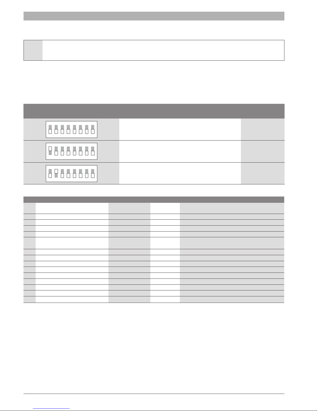
2.4 Dipswitch setting for 2 Burners Cascade
Power switch S1 should only be activated on the managing boiler. Activating more than one switch on the cascade bus may damage the
controller!
For a single burner the address is:
Stand-Alone: All dip-switches OFF.
2 burner cascade addressing:
Group 1 (1-2): All dip-switches OFF, the selected burner number ON.
Dip-switch setting Burner Operation
LabVision
Device Address
ON DIP
Standalone burner 100
1
2 3 4 5 6 7 8
ON DIP
1st burner (managing) 100
1
2 3 4 5 6 7 8
ON DIP
2nd burner (depending) 101
1
2 3 4 5 6 7 8
2.5 Additional device specications
No. Type Brand Congure Article description
1 Flow Sensor Huba Control
2 Water Pressure switch Huba Control Relative pressure switch type 620/625
3 Gas Pressure switches (min.–max) Krom Schroder Gas and air, ¼” NPT, DG 50NT and DG 50HT
5 Sensor Taco Customer Only LWCO probe, no controller, 3/8” P8S-1
6 Burner Customer 150 kW ~ 511BTU/hr
7 Fan ebm-papst
8 Unit Return Temp. Sensor Tasseron Inside NTC sensor - TSD00AE (10k@25°C / 77°F, 3%)
9 Unit Flow Temp. Sensor Tasseron NTC sensor - TSD00AE (10k@25°C / 77°F, 3%)
10 Unit Flue Temp. Sensor Tasseron Inside NTC sensor - TSD20D1 (10k@25°C / 77°F, 3%)
11 System Temp. Sensor Tasseron Inside NTC sensor - TSK10D2 (10k@25°C / 77°F, 3%)
12 Outdoor Temp. Sensor Tasseron Inside NTC sensor - TSRD110-R (10k@25°C / 77°F, 3%)
13 Safety Temp. Sensor Term-o-disc TS18-12491, 100°C / 212°F
14 Unit Flue Pressure Switch Krom Schroder DL4ET-1 330 - 350Pa
15 Unit Condensate Pressure Switch Krom Schroder DL4ET-1 330 - 350Pa
16 Gas valve ebm-papst GB-GD 057 D01 S00
Huba DN25. Flow sensor for liquid media type 200. Flow
range 0,5 … 150 l/min
NRG137 (120VAC PWM)
NRG137/2400-3633-010304-115
6720892984 (2019/02) US SSB
3 BURNERS cascade
1
ON DIP
2 3 4 5 6 7 8
1
ON DIP
2 3 4 5 6 7 8
1
ON DIP
2 3 4 5 6 7 8
3.1 Burner cascade communication setup
In order for the system to work for cascade the communication busses
must be parallel linked together. The managing burner uses the AL-bus
connection on J6 1-8 for burner cascade. The depending burner must be
connected to the managing burner on the J8 AL-bus connection.
It is important that the power on the J8 AL-bus connection on all
depending burners is switched to the OFF position. Also all burners in the
cascade system must have a unique address selected.
Demand: 0-10V / OpenTherm / On-Off
T outside
Boiler sensor
90xMN -
–
–
90xMN D1
J6
Boiler manager
90xMN –
J8
3.2 Setting the burner address (Rev. 4.0.905.15250)
The managing burner of the cascade system is connected to the AL-bus
connection on J6 1-8. This connection also provides the power for the
communication bus. The depending burners are all parallel connected to
the managing burner communication bus.
Since the bus power is provided by the managing burner on J6 1-8,
switch S1 must be set in the OFF position on all controls.
J11
D2
J8
ONOFF
BURNERS cascade | 9
3.2.1 E2prom address selection through e2prom setting
When the Dip-switch conguration is set to disabled the burner address is
selected with an e2prom parameter. This setting can be changed using a
computer with LabVision PC software.
Burner
address
Burner Operation
Function of
sensor input
J5 (7-15)
0 (default) Standalone burner No function 100
1
2
3
4
1st boiler
(Managing)
2nd boiler
(dependent)
3rd boiler
(dependent)
4th boiler
(dependent)
System sensor 100
No function 101
No function 102
No function 103
$ $ $
8
8th boiler
(dependent)
No function 107
3.2.2 E2prom address selection through dip-switch input
When the Dip-switch conguration is set to Cascade burner address
the burner address is selected with the dip-switch input. The switches
are numbered 1 to 8. When an invalid dip-switch setting is selected the
burner address will be set to a standalone burner. When the Dip-switch
conguration is set to Cascade burner address the E2prom parameter is
not used.
Dip-switch setting
ON DIP
Burner
Operation
Standalone burner 100
1
2 3 4 5 6 7 8
ON DIP
1st burner
1
2 3 4 5 6 7 8
(managing)
LabVision Device
Address
LabVision
Device
Address
100
The burner address can be set through an e2prom setting or the
Dip-Switch input available on the control. Which option is used can be
set with the Dip-switch conguration parameter on the Labvision PC
software. Each burner must be congured with its own unique address.
SSB 6720892984 (2019/02) US
ON DIP
1
2 3 4 5 6 7 8
2nd burner
(depending)
101

10 | BURNERS cascade
3.2.3 Communication with LabVision PC software
There are two options for communication with the LabVision PC software.
The 850US Device (Argus-to-USB) can either be parallel connected to
the cascade communication bus or separately to the J8 connection on the
leading burner.
When the 850US Device (Argus-to-USB) is connected to the J8
connection, switch S1 has to be set in the ON position. This powers
the communication bus to allow communication with the Labvision PC
software.
NOTE: there is less information available when connected to the J8
connection on the leading burner. Only the information known by
the leading burner can be shown in the Labvision PC software.
3.3 Cascade – Heating only (Rev. 4.0.905.15250)
Managing burner
When a burner is set as Managing (Address = 1), the controller of this
burner will drive the cascade. The CH mode of this managing burner
applies to all other burners. It is only required to set the CH mode on the
managing burner.
• The outdoor temperature sensor connected to the managing burner
will be the outdoor sensor for the cascade operation
• The system sensor (
will be the control sensor for the cascade supply temperature.
• The (modulating) thermostat connected to the managing burner will
be the CH heat demand input for the cascade system.
Based on the system temperature
Cascade_Setpoint
setpoint, to achieve the requested
The managing burner provides the calculated setpoint to all dependent
burners. The modulating power of the dependent burners is PID
controlled based on the calculated setpoint and dependent burner supply
temperature.
T_System
the managing burner calculates a required burner
) connected to the managing burner
(T_System)
Cascade_Setpoint
and the requested
.
Cascade CH setpoint adaption
When the system temperature is not high enough the setpoint for all
burners will be adjusted.
The boiler setpoint will be increased when the system temperature
drops below
Cascade_Setpoint temperature
This is determined as following:
A PID-control loop over the system temperature
T_System)
the PID controller is between
Up_Limit)
Limit)
calculated boiler setpoint will be limited at
default 80°C (176°F)).
When the system temperature is above cascade setpoint, the calculated
boiler setpoint will be decreased with a step dened by parameter
Slew_Rate_Step_Down
In case the system temperature is below cascade setpoint the calculated
boiler setpoint will be increased with a step dened by parameter
Slew_Rate_Step_Up
The PID calculation does not start immediately but after a certain delay
period to stabilize the system rst.
The delay period is
(settable), for example 60 minutes.
Cascade_Setpoint
and decreased when it rises above
.
(Cascade_Setpoint /
calculates the adjustment of the boiler setpoint. The range of
(Cascade_Setpoint + Max_Range_
and
(Cascade_Setpoint – Min_Range_Down_
. This offset is added to the
Cascade_Setpoint
and then this
CH_Max_Setpoint
(default 1°C (1,8°F)).
(default 1°C (1,8°F)).
Start_PID_Modulation_Delay_Factor
(by
PID_
PID_
6720892984 (2019/02) US SSB
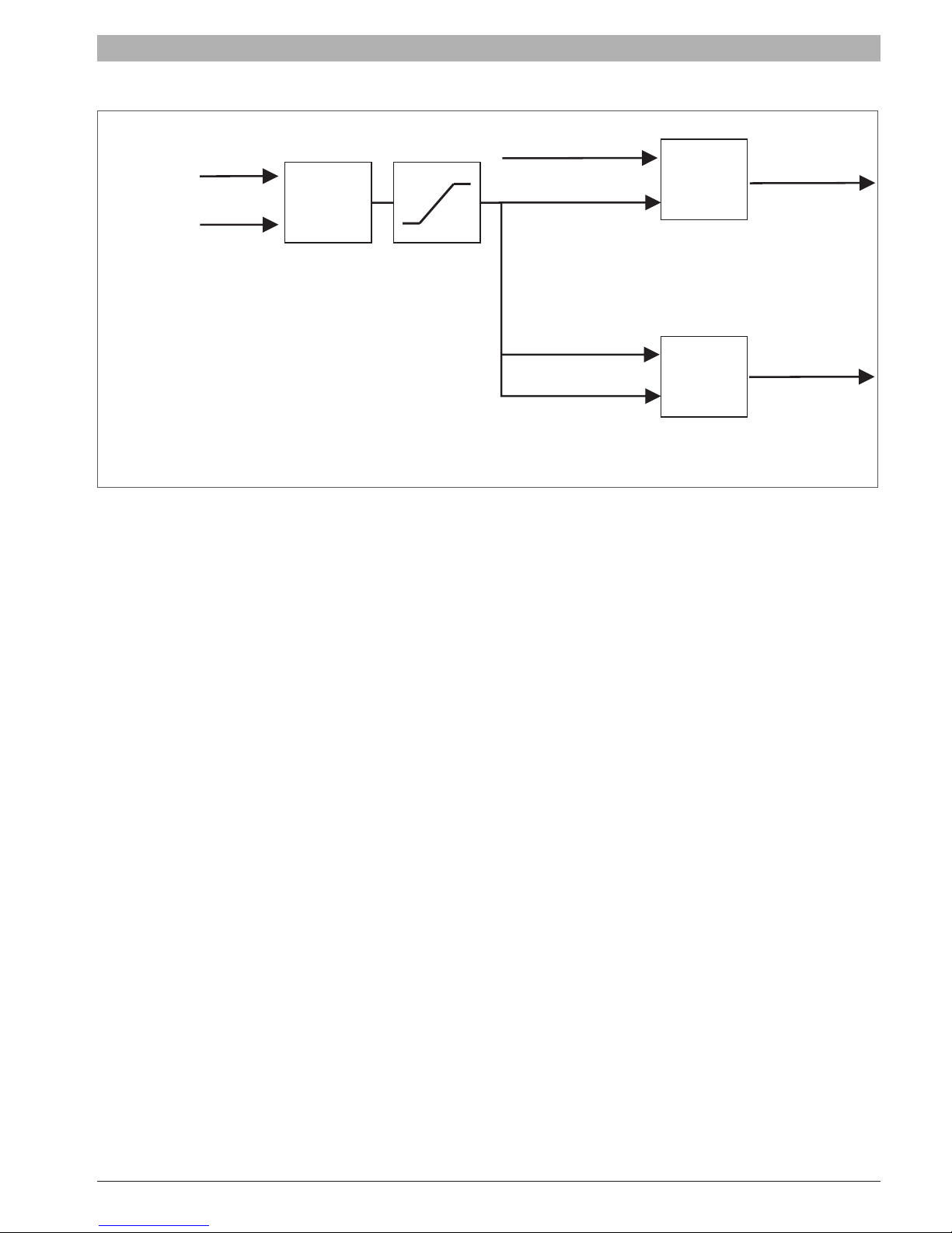
The following diagram shows how the setpoint to the dependents is determined:
BURNERS cascade | 11
T_System
Cascade setpoint
PID slew rate
The changes of the PID output can be limited with the
avoid big setpoint changes to the burners. The slew rate is set in °C/100ms.
For example when the
change a maximum of 1,0°C every 100ms.
The slew rate can be set in steps of 0,1°C/100ms. When set to 0,0°C/100ms the limitation is disabled.
PID_Max_Slew_Rate_Up
PID
System Loop
Offset Setpoint
Calculation
PID_Slew_Rate_Step_Up and PID_Slew_Rate_Step_Down
and
PID_Max_Slew_Rate_Down
T_Supply sensor
Calculated boiler setpoint
T_Supply sensor
Calculated boiler setpoint
are set to 1,0°C/100ms it means the calculated setpoint can
PID
Dependent 1 boiler
PID loop
PID
Dependent 2 boiler
PID loop
(factory settable) setting to
Burner Power
Burner Power
Dependent Burner
The CH mode for the cascade is dened by the setting of the managing burner. CH mode settings on dependents are ignored.
In case a burner is set as dependent (Address = 2-8/16) the setpoint is always provided by the managing burner.
The modulating power of the ALL burners is PID controlled by the burner itself by comparing the calculated setpoint from the managing burner and
T_Supply
The burner of the managing burner itself will be controlled in the cascade system as it would as it was a dependent burner.
Only the pumps and sensor inputs are used.
Burner power
Cascade operation with power modes is designed to work best in cascade systems with equal burners/burners having the same power output.
.
SSB 6720892984 (2019/02) US

12 | BURNERS cascade
3.3.1 Cascade – domestic hot water
Settings
In the installer DHW menu of the managing burner control the
Mode
should be set.
DHW_
Available DHW modes in cascade are mode 1 or 2.
Dependent Burner
In case a burner is set as dependent (Address = 2-8/16) the DHW
setpoint is always provided by the managing burner, the internal control of
the setpoint functions are disabled.
3.3.2 Cascade – DHW priority (Rev. 3.0.0.12377)
Three possible level of DHW and CH heating priority are congurable:
• DHW Priority - BOTH [0]: When both CH and DHW demand have
to be served the priority it is given to the DHW demand for a given
interval (indicated with parameter
DHW_Max_Priority_Timer
).As
soon as the interval has expired the priority switches to CH demand.
The interval time will be reloaded and priority will switch again after
the interval is over.
• DHW Priority - CH [1]: The priority is permanently given to CH
Demand.
• DHW Priority - DHW [2]: The priority is permanently given to DHW
Demand.
• DHW/CH Parallel[3]: The priority us permanently given to DHW
Demand. But Under the following condition the CH pump can started:
Setpoint_CH
< SystemTemp.
3.3.3 Limitation of the MAX power for DHW (Rev. 4.0.905.16570)
When demand change from CH to DHW all burners in the boiler stop
and start DHW demand with a limit amount of burner. The parameter
Max_Active_Dep_DHW
indicates the number of burners available for
N_
DHW. This number will be always be limited in the control to the amount
of burners that is available in the cascade.
Relevant variables
Specic Parameters Level
(Default)
Value
Range
N_Max_Active_Dep_
DHW
Max amount of active burners
per boiler for serve DHW
demand
2: Installer 1 0..16
Relevant variables
Specic Parameters Level
DHW Priority
Both, CH or DHW priority,
Parallel
2: Installer 2 0..3
DHW Max Priority
Timer
[min]
Interval time for switching
the priority
2: Installer 60 1..60
(Default) Value Range
6720892984 (2019/02) US SSB

BURNERS cascade | 13
3.3.4 Cascade – start/stop sequence (Rev. 3.0.0.12315)
The managing burner sends the calculated
Calculated_Setpoint
dependent burners will start or stop using different algorithms.
If a CH or DHW demand request is present, the next dependent burner is always called to ensure that the general (on board) pump of at least one
dependent is always running especially in the case where
In the latter case the Frost protection setpoint is sent to the dependent burner.
Quick Starting and Stopping Burners
When there is a big difference between the
quicker.
and
T_Supply
Cascade_Setpoint
. Depending on the temperature difference between
T_System
and the
to the dependent burners. The power of the burners is PID controlled based on the
T_System
is much higher than the setpoint.
Cascade_Setpoint
the call for a start or stop of the next or last depending is done
T_Header and Header_Setpoint
(CH or DHW) the
• Quick Starting Burners: If the
intervals of
• Quick Stopping Burners: If the
intervals of
Starting and Stopping Burners
With a small difference between
Quick_Start_Interval
Quick_Stop_Interval
T_System
T_Syste
m is
, for example 30 sec.
T_System
is
, for example 30 sec.
and the
Hyst_Down_Quick_Start
Hyst_Up_Quick_Stop
Cascade_Setpoint
the call for a start or stop of the next or last Dependant burner is executed.
degrees below the
degrees above the
Cascade_Setpoint
Cascade_Setpoint
the burners are started at
, the burners are stopped at
SSB 6720892984 (2019/02) US
14 | BURNERS cascade
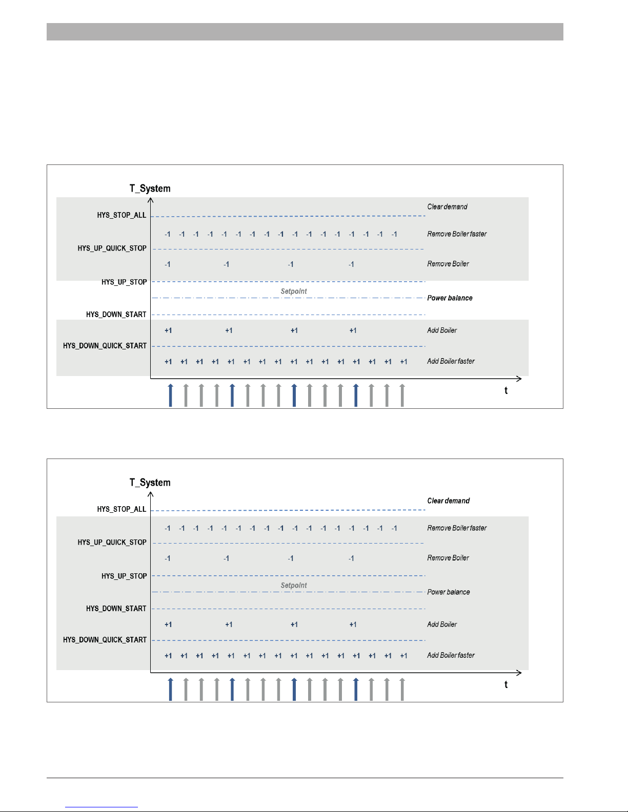
• Starting Burners: If the
Interval, for example 3 min.
• Stopping Burners: If the
Interval
Power balance
When the
See “3.3.5 Cascade – power balance mode (Rev. 4.0.905.15906)” pag. 15.
, for example 3 min.
T_System
T_System
is
Hyst_Down_Start
T_System is Hyst_Up _Sto
is between
Hyst_Down_Start
degrees below the
p degrees above the
and
Hyst_Up_Stop
Cascade_Setpoint
Cascade_Setpoint
a power balance algorithm can be activated.
the burners are started at intervals of Start_
, the burners are stopped at intervals of
Stop_
Stop all dependent
All the dependents are stopped as soon as the
The following graph shows when all the burners are stopped:
T_System
is far greater than
Cascade_Setpoint
.
6720892984 (2019/02) US SSB
Relevant variables
Specic Parameters Level
(Default)
Value
Settable
°C °F °C °F
Delay_ Period_Start_Next_
Burner
[min]
Start Delay Time
Delay_ Period_Stop_Last_
Burner
[min]
Stop Delay Time
Quick_Delay_ Period_
Start_Next_Burner
Quick Start Interval
[sec]
Quick_Delay_ Period_
Stop_Last_Burner
Quick Stop Interval
[sec]
2: Installer
2: Installer
2: Installer
2: Installer
3
(min)
3
(min)
30
(sec)
30
(sec)
1..15
1..15
5..300
5..300
Hyst_Down_Start_Burner
[°C/°F]
Start Burner Diff
2: Installer 5 9 0..20 0..36
Hyst_Up_Stop_Burner
[°C/°F]
Stop Burner Diff
Hyst_Up_Stop_All
Stop Burner Diff
[°C/°F]
2: Installer 5 9 0..20 0..36
2: Installer 30 54 30 54
Hyst_Down_Quick_Start
[°C/°F]
Start Burner Diff in short time
Hyst_Up_Quick_Stop
Stop Burner Diff in short time
2: Installer 10 18 0..20 0..36
[°C/°F]
2: Installer 10 18 0..20 0..36
3.3.5 Cascade – power balance mode (Rev. 4.0.905.15906)
Two different power control modes can be selected to operate the
cascade system.
• Power mode 0:
Power control disabled, each burner modulates based on the system
setpoint.
• Power mode 1:
Power control algorithm to have a minimum amount of boilers/burners
active.
• Power mode 2:
Power control algorithm to have a maximum amount of boilers/
burners active.
• Power mode 3:
Power control algorithm to have a balanced amount of boilers/burners
active.
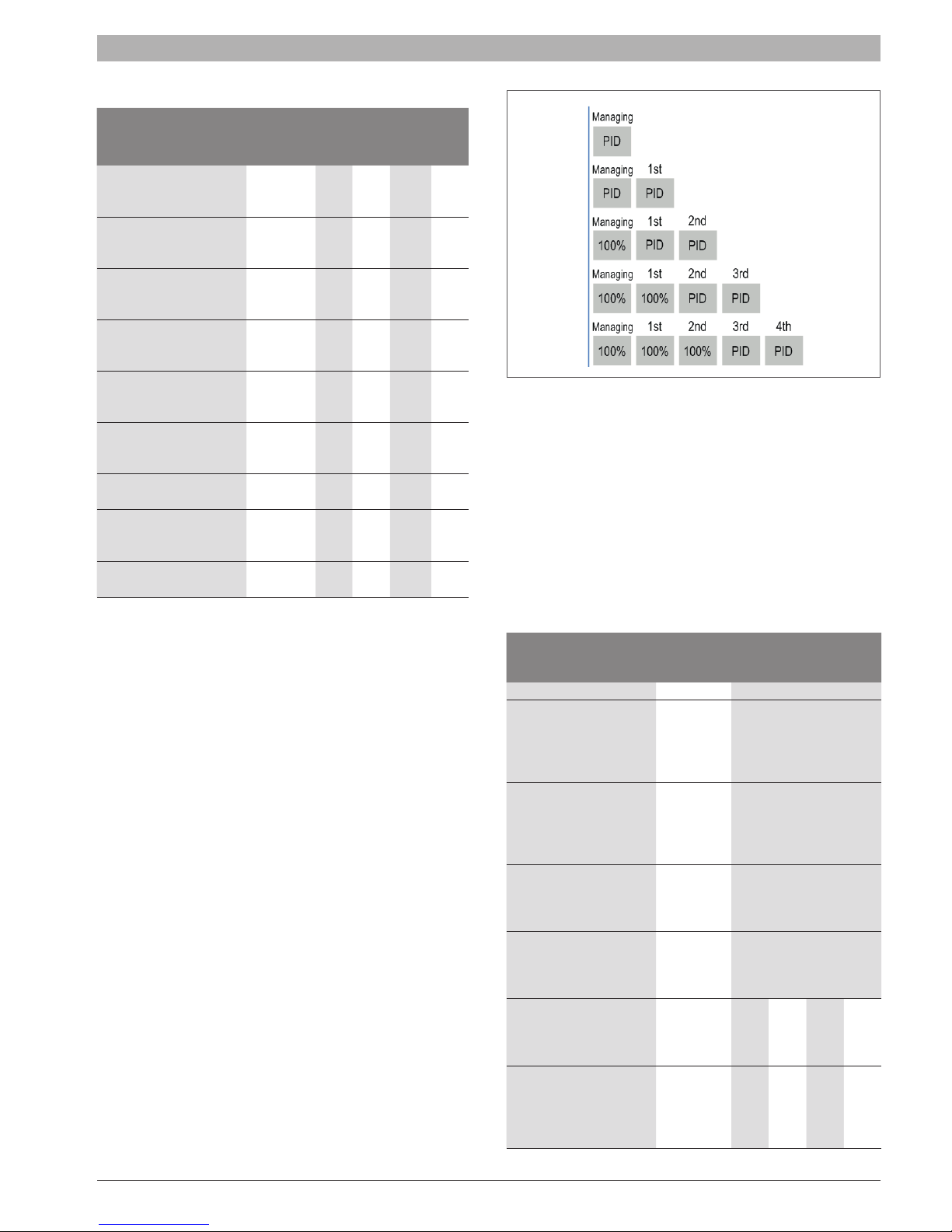
3.3.5.1 Power mode 1 - Minimum burners on (Rev. 4.0.905.15906)
Power Mode 1 guarantees to have as minimum as possible dependent
ON in order to reach the
T_System
.
The modulation of most boilers/burners is forced to 100%, and the last 2
boilers/burners are PID controlled by the setpoint (
from the managing burner in relation to the system temperature (
System
).
Cascade_Setpoint
T_
The last 2 boilers/burners are modulating to make sure that the power
can be adapted to the system temperature without continuous cycling of
the last burner(s).
Below is a picture that shows an example with 4 boilers/burners.
BURNERS cascade | 15
Burner Startup
The next burner is started under the following conditions:
• At least one PID controlled depending is operating at a power [%] >
Start_Rate_Next_Burner
The managing burner forces another burner to 100% power and waits
for 3 min. (
Delay_Period_Start_Next_Dependent
before another burner can be started.
Burner shut down
The last started burner will be stopped under the following conditions:
• All PID controlled depending in burn state Power [%] <
Last_Burner
[%]. The managing burner releases another burner
for PID control and waits for 3 min.(
Dependent
, settable) before another burner can be stopped.
Relevant variables
Specic Parameters Level
Power_Mode 2: Installer 3 0..3
Start_Rate_Next_Burner
Threshold rate before start the
next Burner. Condition: at least 1
depending in burn state power [%] >
Start_Rate_Next_Burner [%]
Stop_Rate_Last_Burner
Threshold rate before start the next
Burner. Condition: all depending in
burn state Power [%] < Stop_Rate_
Next_Burner [%]
Delay_ Period_Start_Next_
Burner
[min]
When the timeout is over the last
dependent can be started
Delay_ Period_Stop_Last_
)
[min]
Burner
When the timeout is over the last
Burner can be stopped
Hyst_Up_Stop_Burner
Hysterese to stop Burner. Condition:
T_System above Header_Setpoint
plus Hyst_Up_Stop_ Burner
Hyst_ Down_Start_Burner
[sec]
Hysterese to stop Burner. Condition:
T_System below Header_Setpoint
plus Hyst_Up_Stop_Burner
[%].
Delay_Period_Stop_Next_
(Default)
Value
°C °F °C °F
[%]
2: Installer 80 1..100
[%]
2: Installer 25 1..100
2: Installer 3 1..15
2: Installer 3 1..15
2: Installer 5 9 0..20 0..36
2: Installer 5 9 0..20 0..36
, settable)
Stop_Rate_
Range
SSB 6720892984 (2019/02) US

16 | BURNERS cascade
3.3.5.2 Power mode 2 – Maximum burners on (Rev. 4.0.905.15906)
Power mode 2 is designed to have as many depending burners on
as possible. When the average burner power of the active depending
burners is above a set minimum power, another burner is started.
Burner startup
The next burner is started under the following conditions:
• When the average burner power of all depending burners is over the
set minimum burner power + hysteresis.
− Sum of burner power of all depending [%] >
power
[%] * (depending in burn + 1) +
power_hysteresis
.
minimum_
minimum_
Burner shut down
The last started burner will be stopped under the following conditions:
• When the average burner power of all depending burners is under the
set minimum burner power.
− Sum of burner power of all depending [%] <
power
[%] * depending in burn.
minimum_
Relevant variables
Specic Parameters Level
(Default)
Value
Range
Power_Mode 2: Installer 3 0..3
Minimum_Power
Minimum average burner power
setting
[%]
2: Installer 20 1..100
Minimum_Power_
Hysteresis
Hysteresis for the minimum average
burner power setting
[%]
2: Installer 40 1..100
3.3.5.3 Power mode 3 – Balanced burners on (Rev. 4.0.905.15906)
Power mode 3 is designed to have a balanced water ow in systems with
a header/manifold.
Burner startup
The next burner is started under the following conditions:
• When the average burner power of all depending burners is over the
set start rate for the next burner.
− Sum of burner power of all depending [%] >
Next_Burner
[%] * depending in burn.
Start_Rate_
Burner shut down
The last started burner will be stopped under the following conditions:
• When the average burner power of all depending burners is under the
set stop rate for the next burner.
− Sum of burner power of all depending [%] <
Next_Burner
[%] * depending in burn.
Stop_Rate_
Relevant variables
Specic Parameters Level
(Default)
Value
Range
°C °F °C °F
Power_Mode 2: Installer 3 0..3
Start_Rate_Next_Burner
Threshold rate before start the
next Burner. Condition: at least 1
depending in burn state power [%] >
Start_Rate_Next_Burner [%]
Stop_Rate_Last_Burner
Threshold rate before start the next
Burner. Condition: all depending in
burn state Power [%] < Stop_Rate_
Next_Burner [%]
[%]
2: Installer 80 1..100
[%]
2: Installer 25 1..100
Delay_ Period_Start_Next_
Burner
[min]
When the timeout is over the last
dependent can be started
2: Installer 3 1..15
Delay_ Period_Stop_Last_
[min]
Burner
When the timeout is over the last
Burner can be stopped
2: Installer 3 1..15
Hyst_Up_Stop_Burner
Hysterese to stop Burner. Condition:
T_System above Header_Setpoint
plus Hyst_Up_Stop_ Burner
2: Installer 5 9 0..20 0..36
Hyst_ Down_Start_Burner
[sec]
Hysterese to stop Burner. Condition:
T_System below Header_Setpoint
plus Hyst_Up_Stop_Burner
2: Installer 5 9 0..20 0..36
6720892984 (2019/02) US SSB

BURNERS cascade | 17
3.3.6 Cascade – burner rotation (Rev. 4.0.905.x)
The burner rotation function can change the start/stop sequence for the
cascade burners.
The parameter
after which the sequence is updated.
When
disabled.
When the parameter
the burner rotation days left will be initialized to the new
Rotation_Interval
When for example
is as following (x is the last burner):
Days Start/Stop sequence
Day 0-5 1-2-3-4-5..x
Day 5-10 2-3-4-5..x-1
Day 10-15 3-4-5..x-1-2
Day 15-20 4-5..x-1-2-3
Day 20-25 5..x-1-2-3-4
With parameter
that is rst to start in the sequence is selected.
When the burners are rotated the parameter
Start
is automatically updated to the next depending.
When burner rotation is disabled the parameter
To_Start
When the
control will clear all demand of the cascade control. After this it will
start cascade demand generation with the new selection for
Depending_To_Start
Relevant variables
Specic Parameters Level
Burner_Rotation_Interval 2: Installer 5
First_Depending_To_Start 2: Installer 1 1..8/16
Burner_Rotation_Interval
Burner_Rotation_Interval
Burner_Rotation_Interval
setting.
Burner_Rotation_Interval
First_Depending_To_Start
is reset to 0.
First_Depending_To_Start
.
sets the number of days
is set to 0 burner rotation is
is updated
Burner_
= 5 the start sequence
the current depending
First_Depending_To_
First_Depending_
is manually changed the
First_
(Default)
Value
Range
0..30
0 = Disable
3.3.7 Cascade – error handling
3.3.7.1 Emergency mode
Open / Shorted boiler or system sensor
When the setting “
the control can go into emergency mode when the system sensor status
is not ok. When the system sensor is open or shorted the control goes
into the emergency mode.
The managing burner display may show that the system is in emergency
mode.
In emergency mode the system setpoint is set to the
Emergency_Setpoint
When an emergency heat demand is generated all burners are allowed to
start burning on this setpoint.
Loss of cascade communication (Rev. 3.0.0.14038)
The leading board is aware of how many dependents should be present
in the system. This value is stored in the e2prom. When powering on the
system the leading burner has to detect all depending burners within 60
seconds.
When not all dependent burners are detected the control will show the
CC_LOSS_COMMUNICATION
When the communication with any of the depending burners is lost during
operation the control will show the
CC_LOSS_COMMUNICATION
CC_LOSS_COMMUNICATION
The
not block the control.
3.3.7.2 Managing burner error (Rev. 3.0.0.11748)
When the managing burner is in error mode this burner is not used
anymore for the cascade system.
However depending on the error code, the pumps connected by the
managing burner still can be active for the cascade system. When the
managing unit is reset from lockout state, the cascade controllers are
re-initialized.
Permit_Burner_Emergency_Mode
(settable via installer menu).
warning.
warning after 60 seconds.
warning is purely informative and will
” is enabled
Cascade_
SSB 6720892984 (2019/02) US
18 | Service display
4 Service display
4.1 General
4.1.1 Introduction
The 900PB Display is an advanced graphical user interface for
applications such as HMI for heating appliances.
It can be used in combination with other epHS controls and
communicates with these controls via the AL-BUS connection.
This manual is applicable for layout versions:
• 900PB06_3R
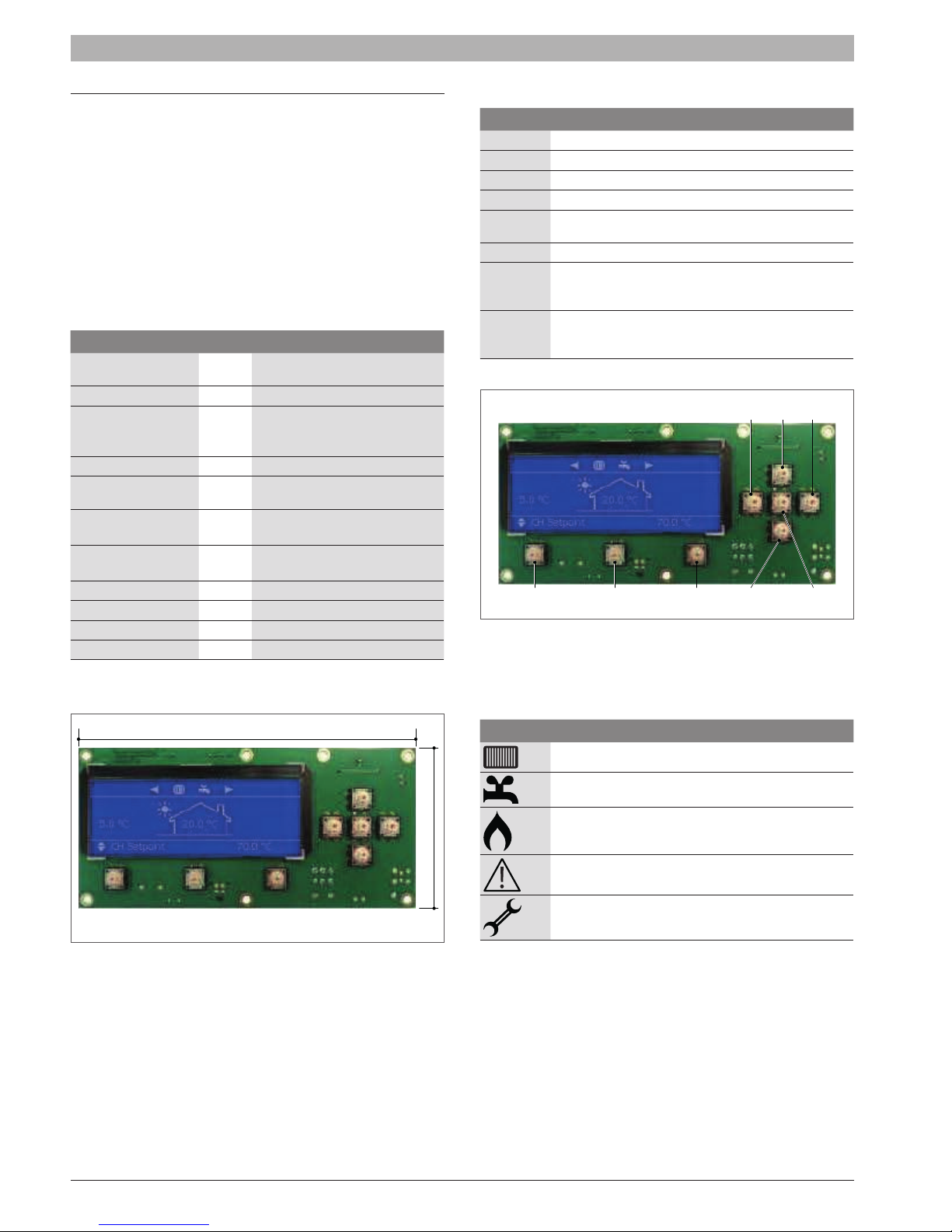
4.1.2 General information
Dimensions PCB
L × W
× H
Operating temperature 0°C to +50°C (32°F to 122°F)
Connections
LCD mode 255 x 80 Dot graphic
Module dimensions
W × H
× T
Viewing area W × H
Active area W × H
Dot size W × H 0.34 x 0.37
Dot pitch W × H 0.37 x 0.40
LCD display mode TN/Blue/Negative/Transective
Viewing direction 12 O’clock
900PB06_3R:
900PB0X_3R: 178x85x13mm
(7,01”x3,35”x0,51”)
See “Appendix J - PB Connectors
Description” pag. 65
121,4x47,6x5,0mm
(4,78”x1,87”x0,2”)
106,4 x 39,0mm
(4,19”x1,54”)
95,0 x 32,0mm
(3,74”x1,26”)
4.1.3 Display functions
Button Function
RESET Reset Lockout error
MENU Enter the main menu
ESC Return to the Status overview
LEFT Return to previous menu item or Status overview
RIGHT
Enter a menu item or conrm selection in Status overview
(when directly setting Actual setpoint or DHW setpoint)
ENTER Conrm a setting or enter a menu item
Directly select Actual setpoint of DHW setpoint in the
UP
Status overview, push RIGHT to conrm and use UP or
DOWN to adjust value
Directly select Actual setpoint of DHW setpoint in the
DOWN
Status overview, push RIGHT to conrm and use UP or
DOWN to adjust value
RIGHTLEFT
UP
RESET MENU ESC DOWN
ENTER
4.1.4 Display icons
The following table gives a short description of the icons that can be
visible on the main screen during operating:
178
1 = 1 mm
85
Icon Description
Central Heating demand
Domestic Hot Water demand
Indicates that the appliance burner is ON
Cascade Emergency Mode active
Error notication
6720892984 (2019/02) US SSB
Service display | 19
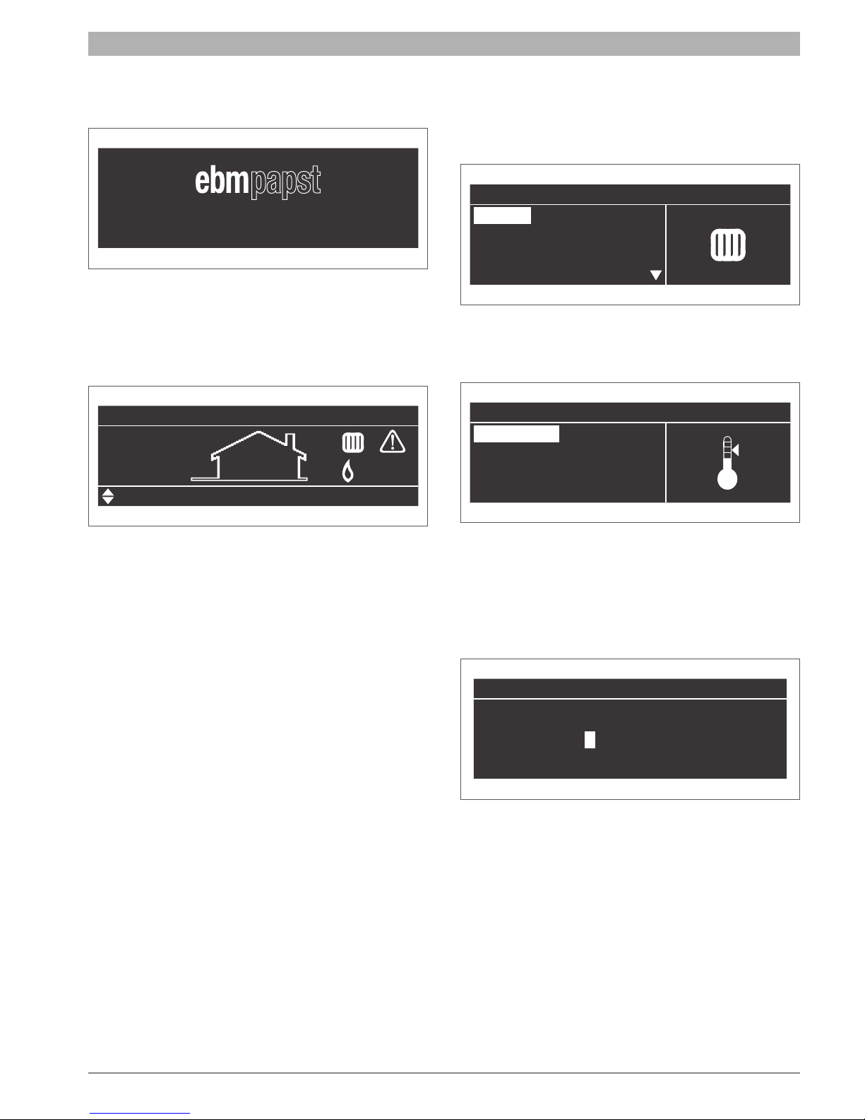
4.2 Screens
4.2.1 Splash screen (Rev 1.1.0.13425)
Heating System B.V.
This screen is active during power up and will remain active until
communication with the Main Control (the AL-BUS) has been established.
Standard no default start-up screen is installed, only the text “initializing”
will appear (for certain projects a ‘Settings parameter is available to select
a customized splash screen).
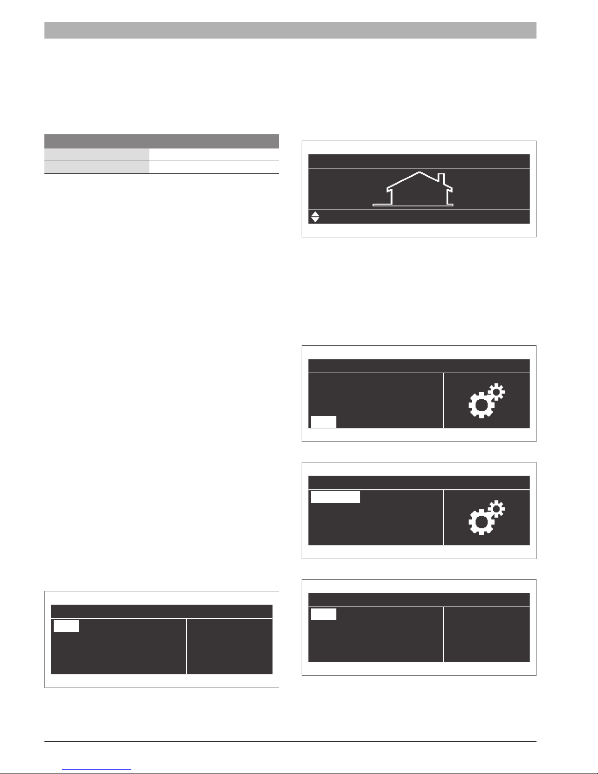
After communication has been established the following Status overview
appears:
10.0°C
4.2.2 Entering the menu
Enter the menu by pressing the MENU button once. The header in the
screen shows you are inside the main menu.
While scrolling through the menu you will see that the selected menu item
is shown in a white rectangle.
Menu
Heating
Sanitary Water
Information
Settings
Enter a menu item by pressing ENTER or RIGHT.
The header shows your location inside the menu, as seen in the following
image on the next page:
Heating
CH Setpoint
Climatic Compensation
Actual Setpoint
Set Actual setpoint/DHW setpoint directly via the Status overview
When CH is active, you can adjust the Actual setpoint directly on the
bottom of the Status overview.
When DHW is active, you can adjust the DHW setpoint directly on the
bottom of the Status overview.
This means that when CH is active, you cannot set the DHW setpoint
directly via the Status overview.
When DHW is active, you also cannot set the Actual setpoint (CH
setpoint) directly via the Status overview.
Press UP/DOWN to select the mode, then press ENTER/RIGHT to
conrm the mode and the Actual/DHW setpoint becomes directly settable.
Use UP/DOWN to increase/decrease the setpoint.
Press ENTER/RIGHT to conrm your alteration or press BACK/LEFT to
cancel.
A setpoint is only visible on the main screen when no error or alert is
active. In case of an active error or alert, the bottom right part of the PB
screen is used to display the error or alert text.
Disable the DHW Service (only for Storage appliance with 850MN)
It is possible to disable the DHW service by keeping pressing ENTER for
5 seconds.
The display will then show the string “Standby” on the Status overview.
The request for demand will be ignored in the following cases:
• DHW REQUEST demand
• STORAGE COLD demand
• PRE HEAT demand
• TAP FLOW demand
Press the ENTER button again for 5 seconds in order to re-enable the
DHW service.
50.0°C
If you are inside the menu (or a menu item) and want to return directly to
the Status overview press MENU/ESC.
If you want to go back one step in the menu press BACK/LEFT.
4.2.3 Protected menu items
Some menu items are protected and only accessible via a password*.
The following password screen will then appear:
Password
0 * * *
Enter the password with the following steps:
1 Use the UP/DOWN button to adjust the rst number
2 Press ENTER or RIGHT to conrm and to go to the following number.
3 Enter 0300.
SSB 6720892984 (2019/02) US
20 | Service display
Repeat this action for all numbers to enter the password.
During this action, if you want to return to the previous screen, just press
MENU or ESC to cancel.
After the password is entered in correctly, the menu item will become
available.
The following menu items require a password*:
(Sub) Menu item Location inside menu
Climatic Compensation via ‘Heating > Climatic compensation’
Boiler via ‘Settings > Boiler’
* Passwords for different user levels are always customer specic and will
be provided by epHS to the appliance manufacturer only (due to safety
reasons).
4.2.4 DAir Sequence
The “De-Air” sequence is a safety function that starts at every power ON
and is used to remove the air from the heater-exchanger.
The DAir sequence does not start after a general reset (like the locking
error reset or 24 hours reset)
The display will show the following string during DAir sequence:
• “Dair Running”
• “Dair Error Water Pressure”
The DAir sequence can be canceled by the user by pressing the OK
button for over 5 seconds.
Press ESC to go back in the menu and return to the Status Indication
screen.
No matter what language you set, the menu icons will always remain
universal.
4.2.5.2 Set the display language from Chinese back to English
First, make sure you the Status Indication screen is displayed, which
looks as following:
12 09
16.5°C
生活热水温度设定
If this is not the case, press the ESC button a couple of times until you
return to this screen.
The following steps describe how to set the display from Chinese back to
English:
[1] Press the MENU button once to enter the main Menu (菜单)
[2] Select “Settings” (设置) and press the ENTER button to access this
menu:
49.0°C
4.2.5 Language settings
The 900PB display has a number of different language options, such as
English, French, Chinese and Italian.
Paragraph 4.2.5.1 describes how to set the display language (and
characters) to Chinese.
Paragraph 4.2.5.2 describes how to set the language back from Chinese
to English (or any other language).
4.2.5.1 Set the display language to Chinese
Please follow the next steps, which describe how to set the display
language to Chinese:
[1] From the Status Overview, press the MENU button once
[2] Select “Settings” and press the ENTER button
[3] Select “General Settings” and press the ENTER button
[4] Select “Language” and press the ENTER button
[5] Select the Chinese language (中文) and press ENTER
After the Step 5 the text and menu items will automatically be displayed
in Chinese:
基本设置
语言
单位类型
日期时间
Aα
其他设置
菜单
供暖
生活热水
Info
设置
[3] Select “General Settings” (基本设置) and press the ENTER button:
设置
基本设置
锅炉设置
[4] Select “Language” (语言) and press the ENTER button:
基本设置
语言
单位类型
日期时间
Aα
其他设置
6720892984 (2019/02) US SSB

[5] Select the desired language (“English“) and press ENTER to
conrm: (For setting the display to French: select “Français”, for
Italian select “Italiano”)
语言
English
Français
中文
Italiano
Once you have set the English language, the screen will display its
information in English again:
General setting
Language
Unit Type
Date & Time
Aα
Other Setting
Service display | 21
Press ESC to go back in the menu and return to the Status Indication
screen.
SSB 6720892984 (2019/02) US

22 | Service display
4.3 Menu Structure
Below is a schematic overview of the menu structure of 900MN control.
Main menu Menu item Submenu / Parameter Sub item Value / Unit User level 900MN
Central Heating CH Setpoint CH Setpoint
Climatic
Compensation
Setpoint_Max
Setpoint_Min
Outdoor_Max
Outdoor_Min
WW_Shutdown
°C/°F
°C/°F
°C/°F
°C/°F
°C/°F
°C/°F
1: User •
2: Installer •
2: Installer •
2: Installer •
2: Installer •
2: Installer •
Sanitary Water DHW Setpoint
Information Boiler DHW Temp
DCW Temp
Fan Power
Flow Temp
Flow 2 Temp
Flue Temp
Flue 2 Temp
Outside Temp
Return Temp
System Temp
0 – 10V Input
Flow Rate
RT Input
Water Pressure
Ionization
Burner State 1: User •
Error No.
Actual setpoint
Settings General Language English 1: User
Italian 1: User
Unit type Metric
Imperial
Date/Time Date
Time
System information Display
Boiler
Solar
Zone
Device group
Modbus Address
Boiler (1) CH Mode
(2) Mod Pump Mode
(3) CH Setpoint
(*) Calc. Setp. Offset
(4) CH Pump Overrun
(5) General Pump Overrun
(6) Flue Temp ABS Limit
(7) CH Hyst
°C/°F
°C/°F
°C/°F
RPM
°C/°F
°C/°F
°C/°F
°C/°F
°C/°F
°C/°F
°C/°F
V
l|min.
Open/Closed
bar/psi
uA
#
°C/°F
°C, Bar, etc.
°F, PSI, etc.
dd-mm-year
00:00
[####] *
[####] *
[####] *
[####] *
###MN
0-255
0-6
0-4
°C/°F
°C/°F
Sec.
Sec.
°C/°F
°C/°F
1: User •
1: User •
1: User •
1: User •
1: User •
1: User •
1: User •
1: User •
1: User •
1: User •
1: User •
1: User •
1: User •
1: User •
1: User •
1: User •
1: User •
1: User •
1: User
1: User
1: User
1: User
1: User •
1: User •
1: User
1: User
1: User •
1: User
2:Installer •
2:Installer
1: User •
2:Installer •
2:Installer
2:Installer •
3:Factory •
2:Installer •
6720892984 (2019/02) US SSB

Service display | 23
Main menu Menu item Submenu / Parameter Sub item Value / Unit User level 900MN
(7) CH Hyst Up
(*) CH Hyst Down
* Checksum software version
Main menu Menu item Submenu / Parameter Sub item Value / Unit User level 900MN
(8) Flue Gas Diff
(9) Anti Cycle Period
(10) Anti Cycle T Diff
(11) Ramp Delay Step Mod
(12) Hx Diff Delta Tmin
(13) Hx Diff Max Wait Time
(14) P CH Max
(15) P CH Min
(16) CH PID P 3: Factory •
(17) CH PID I 3: Factory •
(18) CH PID D 3: Factory •
(19) High CH Setpoint
(20) Outdoor Temp For Hi Setp
(21) Low CH Setpoint
(22) Outdoor Temp For Lo Setp
(23) CH Setpoint Min.
(24) CH Setpoint Max.
(25) Warm Weather Shutdown
(26) Boost Temp. Incr.
(27) Boost Time Delay
(28) Night Setback Temp.
(29) Weather Setpoint
(30) HydroAir CH Hyst Down
(31) HydroAir CH Hyst Up
(32) HydroAir CH PID P 3: Factory
(33) HydroAir CH PID I 3: Factory
(34) HydroAir CH PID D 3: Factory
(35) DHW Mode
(*) P DHW Max
(*) P DHW Min
(36) DHW Storage Hyst Dn
(37) DHW Storage Hyst Up
(38) DHW Store Supply Extra
(39) DHW Store Supp Hyst Dn
(40) DHW Store Supp Hyst Up
(41) DHW Store Hold Warm
(42) DHW Priority
(43) DHW Max Priority Time
(44) Post Pump DHW Time
(45) DHW Store PID P 3: Factory •
(46) DHW Store PID I 3: Factory •
(47) DHW Store PID D 3: Factory •
(48) DHW Setpoint
(49) DHW Hysterese Down
(50) DHW Hysterese Up
(51) DHW Instant PID P 3: Factory •
°C/°F
°C/°F
°C/°F
Sec.
°C/°F
On/Off
°C/°F
Sec.
%
%
°C/°F
°C/°F
°C/°F
°C/°F
°C/°F
°C/°F
°C/°F
°C/°F
Min.
°C/°F
°C/°F
°C/°F
°C/°F
0-5
%
%
°C/°F
°C/°F
°C/°F
°C/°F
°C/°F
°C/°F
0-2
Min.
Sec.
°C/°F
°C/°F
°C/°F
2:Installer •
2:Installer •
3: Factory
2: Installer •
2: Installer •
2: Installer
3: Factory •
3: Factory •
2: Installer •
2: Installer •
2: Installer •
2: Installer •
2: Installer •
2: Installer •
2: Installer •
2: Installer •
2: Installer •
2: Installer •
2: Installer •
2: Installer •
2: Installer
3: Factory
3: Factory
2: Installer •
2: Installer •
2: Installer •
2: Installer •
2: Installer •
2: Installer •
3: Factory •
3: Factory •
3: Factory •
2: Installer •
2: Installer •
2: Installer •
1: User •
3: Factory •
3: Factory •
SSB 6720892984 (2019/02) US

24 | Service display
Main menu Menu item Submenu / Parameter Sub item Value / Unit User level 900MN
(52) DHW Instant PID I 3: Factory •
(53) DHW Instant PID D 3:Factory •
(54) Tap Detect DHW Drop
(55) Tap Detect Hyst Dn
(56) TapFlow Max Time
(57) Tap Det Hold Active Time
(58) Tap Det Stop Diff SupRet
(59) Tap Det Stop Diff RetDhw
(60) Flow Rate Start
(61) Flow Rate Lo Temp Pwr
(62) Flow Rate Hi Temp Pwr
(63) DHW On Off Period
(64) PH Mode
(65) PH Eco Setpoint
(66) PH Hold Time
(67) PH After Tap Hold Time
(68) After Tap Hold Time
(69) PreHeat Hyst Down
(70) PreHeat Hyst Up
(71) PreHeat Delay Time
(72) Permit EmergencyMode
(73) Boiler Address
(74) Cas Emergency Setpoint
(75) Delay Per Start Next Dep
(76) Delay Per Stop Next Dep
(*) Delay Per Quick Start Next Dep
(*) Delay Per Quick Start Next Dep
(77) Hyst Down Start Boiler
(78) Hyst Up Stop Boiler
(*) Hyst Down Quick Start Boiler
(*) Hyst Up Quick Stop Boiler
(*) Hyst Up Stop All Boilers
(79) Max Setp Offset Down
(80) Max Setp Offset Up
(81) Start Mod Delay Fact
(82) Next Boiler Start Rate
(83) Next Boiler Stop Rate
(84) Boiler Rotation Interval
(*) Boiler First to Start 2:Installer •
(85) DHW Boiler Assign
(86) Casc PID P 3:Factory •
(87) Casc PID I 3:Factory •
(88) Casc PID Slew Rate 3:Factory
(*) Casc PID Slew Rate Up 3:Factory •
(*) Casc PID Slew Rate Down 3:Factory •
(89) Frost Protection
(90) Frost Protection Setpoint
(91) DHW Max Setpoint
(92) Fan Speed Maximum
(93) Fan Speed Minimum
(94) Fan Speed Ignition
(95) Gas Type
°C/°F
°C/°F
Sec.
Sec.
°C/°F
°C/°F
l/min / gpm
l/min / gpm
l/min / gpm
Sec.
Comfort, Eco
°C/°F
Sec.
Sec.
Sec.
°C/°F
°C/°F
Sec.
Yes/No
0-16
°C/°F
Sec.
Sec.
Sec.
Sec.
°C/°F
°C/°F
°C/°F
°C/°F
°C/°F
°C/°F
°C/°F
Min.
%
%
Days
0-16
On/Off
°C/°F
°C/°F
RPM
RPM
RPM
0-4
3:Factory
3:Factory
3:Factory
3:Factory
3:Factory
3:Factory
3:Factory •
3:Factory •
3:Factory •
3:Factory •
1:User •
3:Factory •
3:Factory
3:Factory •
3:Factory •
3:Factory •
3:Factory •
3:Factory •
1:User •
2:Installer •
2:Installer •
2:Installer •
2:Installer •
2:Installer •
2:Installer •
2:Installer •
2:Installer •
2:Installer •
2:Installer •
2:Installer •
2:Installer •
2:Installer •
2:Installer •
2:Installer •
2:Installer •
2:Installer •
2:Installer
2:Installer
2:Installer
2:Installer
2:Installer •
2:Installer •
2:Installer •
3:Factory
6720892984 (2019/02) US SSB

Service display | 25
Main menu Menu item Submenu / Parameter Sub item Value / Unit User level 900MN
(*) Prog. Input 1.
(*) Prog. Input 2.
(*) Prog. Input 3.
(*) Prog. Input 5.
(*) Prog. Input 6.
(*) Prog. Input 7.
(*) Prog. Input RT.
(*) Prog. Output 1.
(*) Prog. Output 2.
(*) Prog. Output 3.
(*) Flow Sensor 2:Installer •
(*) Flow Scaling Factor
(*) Min Pressure
(*) Pressure Fill Hyst.
(*) Service Reminder
(*) Service Status
(*) Mod. Pump dT
(*) Mod. Pump Start Time
(*) Mod. Pump Type 2:Installer •
(*) Mod. Pump Mode 2:Installer •
(*) Mod. Pump Min Pwr
(*) Appliance Type
(*) Min Flow 2:Installer •
(*) Nominal Flow 2:Installer •
0-4
0-2
0-2
0-2
0-3
0-4
0-1
0-5
0-3
0-2
RMP/l
bar/psi
bar/psi
Days
On/Off/Reset
°C/°F
Sec.
%
0-4
2:Installer •
2:Installer •
2:Installer •
2:Installer •
2:Installer •
2:Installer •
2:Installer •
2:Installer •
2:Installer •
2:Installer •
2:Installer •
2:Installer •
2:Installer •
2:Installer •
2:Installer •
2:Installer •
2:Installer •
2:Installer •
2:Installer •
Main menu Menu item Submenu / Parameter Sub item Value / Unit User level 900MN
Test mode
Test Status OFF
Power FAN MAX 1:User •
Fan Speed O RPM
OFF
CH MAX 1:User •
O RPM
OFF
LOW 1:User •
O RPM
OFF
IGNIT 1:User •
O RPM
OFF
HIGH 1:User •
O RPM
OFF
OFF 1:User •
O RPM
OFF
LWCO1 1:User •
O RPM
OFF
LWCO2 1:User •
O RPM
OFF
MAX TEMP 1:User •
O RPM
SSB 6720892984 (2019/02) US

26 | Main control
5 Main control
5.1 Ignition cycle (Rev 3.0.0.0)
The table below shows the states of the burner ignition cycle.
Control state Actions
Fan is not running
Pre purge 0
Pre purge 1
Pre ignit
Ignit
Flame
proving
Burn
Post purge 0
Post purge 1
When an air pressure switch (APS) is enabled the APS
position is checked.
Fan starts at ignition speed
When an APS is enabled the APS position is checked
Fan stays at ignition speed
Igniter is started
When a LPG tank is selected, the tank valve is opened
Fan stays at ignition speed
The gas valve is opened
Igniter stays on
When a LPG tank is selected, the tank valve stays
opened
Fan stays at ignition speed
The gas valve stays opened
The igniter is stopped
When a LPG tank is selected, the tank valve stays
opened
The fan is modulating
The gas valve stays opened
When a LPG tank is selected, the tank valve stays
opened
When an APS is enabled the APS position is checked
The fan is set at ignition speed
The gas valve is closed
When a LPG tank is selected, the tank valve is closed
Fan stays at ignition speed
When an APS is enabled the APS position is checked
The fan speed is continuously monitored. The following
conditions for the fan speed are checked.
Fan
supervision
• The actual fan speed must be within 300rpm of the
target fan speed
• When in the burn state both the actual and target
fan speeds are above 4200rpm, the check on the
300rpm range is not performed.
5.2 Control functions
Dependent on the required functions of the appliance and connected
sensors and components, several operation modes for Central Heating
(CH) and Domestic Hot Water (DHW) can be selected.
5.2.1 Demand for central heating (Rev 3.0.0.0)
5.2.1.1 CH Mode 0 - Central Heating demand
For this mode the CH mode should be set to 0 and no outdoor sensor is
needed.
If the room thermostat closes, the pump is switched ON. When the supply
temperature drops
(settable via the menu) the burner is switched ON. The power for the
burner is PID regulated between
the PID parameters for Central Heating (Also see chapter “Appendix G PID: Proportional-Integral-Derivative controller” pag. 59).
If the supply temperature reaches a temperature
above the
However, if
maximum setpoint the burner switches OFF at the maximum setpoint.
If the room thermostat opens the burner is switched OFF (if this was
not already happening) and the CH and general pumps run ON for
CH_Post_Pump_Time
CH_Hysterese_Down below the CH_Setpoint
T_Supply
and the
CH_Setpoint
CH_Hysterese_Up
CH_Setpoint
CH_Setpoint + CH_Hysterese_Up
the burner is switched OFF.
is greater than
.
using
During the ignition cycle there are multiple safety checks active.
False ame
detection
Re-ignition
Flame
establishing
time
Flame out too
late
Flame loss
If ame is detected at the end of the pre-spark period
(
Pre ignit
If at the end of the safety period no ame is detected
the control will go to post-purge to remove the unburned
gas. After this a re-ignition attempt is started following
the same cycle.
The number of re-ignition attempts is limited to
Ignit_Trials
Sparking stops in the
for ionization detection.
The Flame proving state takes
) a lockout error occurs
after which a lockout occurs.
Flame proving
SAFETY_PERIOD -
state to allow
IGNIT_PERIOD.
If at the end of the Post purge 0 state the ame is still
detected a lockout follows.
When a ame is lost during a burn cycle the control will
restart the burner. The number of restarts is limited by
the
max_ame_trials
setting.
Max_
Anti-cycling time
(This function is also applicable to all other CH modes)
When the burner is switched OFF because the supply temperature
CH_Setpoint + CH_Hysterese_Up
reaches
period of time (
is allowed to be switched ON again.
This function is to prevent fast switching ON and OFF of the burner.
However, when during the anti-cycle wait time the differential between
setpoint and supply temperature gets greater than
anti-cycle
Maximum CH power
(This function is also applicable to all other CH modes)
The maximum burner power during CH operation can be limited with
parameter
Minimum CH power
(This function is also applicable to all other CH and DHW modes)
• The minimum burner power during operation can be limited with
parameter
Anti_Cycle_Period
will be aborted and the burner is allowed to start.
P_CH_Max
.
P_CH_Min
.
¨ 180 sec. settable) before it
, the control will wait a
Anti_Cycle_T_Diff,
6720892984 (2019/02) US SSB
 Loading...