

Bosch SRU53E05AU Repair Instructions

R
R
R
E
E
E
P
P
P
A
A
A
I
I
I
R
R
R
I
I
I
N
N
N
S
S
S
T
T
T
R
R
R
U
U
U
C
C
C
T
T
T
I
I
I
O
O
O
N
N
N
Dishwasher
815_58300000120057_ara_en_d.doc – 25.05.11 Seite 1 von 60
1 SAFETY........................................................3
2 INSTALLATION............................................4
2.1 Aligning the appliance........................................................ 4
2.2 Electrical connection..........................................................4
2.3 Water connection................................................................4
3 OPERATION.................................................5
3.1 Control panel.......................................................................5
3.2 LEDs..................................................................................... 5
3.3 Main switch..........................................................................5
3.4 Pushbuttons / Additional functions .................................. 5
3.5 Programme selector switch............................................... 6
3.6 Setting the hardness range................................................ 6
3.7 Reset....................................................................................6
4 COMPONENTS.............................................7
4.1 Module ................................................................................. 7
4.2 Actuator.............................................................................10
4.3 Aqua sensor (optional).....................................................11
4.4 Aqua Stop valve................................................................12
4.5 Flow sensor.......................................................................13
4.6 NTC .................................................................................... 14
4.7 Salt and rinse-aid indicators (optional)........................... 15
4.8 Optical low rinse-aid sensor (optional)...........................16
4.9 Dispenser...........................................................................17
4.10 Water softening system................................................... 18
4.11 Regeneration valve........................................................... 19
4.12 Filter system ..................................................................... 20
4.13 Rinsing and pumping system.......................................... 21
4.14 Door spring ....................................................................... 22
4.15 Circulation pump (SICASYM) .......................................... 23
4.16 Instantaneous water heater ............................................. 24
4.17 Detergent-solution pump................................................. 25
4.18 Level sensor with safety function................................... 26
1.1 Water inlet without heat exchanger ................................ 27
4.19 Water points...................................................................... 28
5 FUNCTIONS................................................29
5.1 3 in 1 detergents............................................................... 29
6 REPAIR.......................................................30
6.1 Installing the module........................................................ 30
6.2 Replacing the Aqua Stop valve ....................................... 31
6.3 Worktop (optional)............................................................ 32
6.4 Removing and installing dispenser ................................ 33
1.1 Axial flow sensor.............................................................. 34
6.5 Removing and installing circulation pump .................... 35
6.6 Detergent-solution pump................................................. 37
6.7 Removing and installing hinge........................................ 38
6.8 Water softening system................................................... 40
6.9 Instantaneous water heater ............................................. 41
6.10 Replacing the door seal................................................... 42

815_58300000120057_ara_en_d.doc – 25.05.11 Seite 2 von 60
6.11 Diagnosis aids...................................................................43
7 FAULT DIAGNOSTICS...............................44
7.1 Draining .............................................................................44
7.2 Odour.................................................................................45
7.3 Noises................................................................................46
7.4 Rinsing result....................................................................47
7.5 Drying result...................................................................... 56
7.6 Circulation pump ..............................................................57
7.7 Control unit/module/cable harness.................................58
8 TECHNICAL SPECIFICATIONS ................59
8.1 General technical specifications..................................... 59
8.2 Consumption rates ........................................................... 60
815_58300000120057_ara_en_d.doc – 25.05.11 Seite 3 von 60
1 SAFETY
DANGER
Repairs may be carried out by a qualified electrician only!
The user may be put at risk and injured by improper repairs!
To prevent electric shocks, always comply with the following
instructions:
► If the appliance is faulty, the housing or frame may be
live!
► Electric shock may occur if live components are touched
inside the appliance!
► Before commencing repairs, disconnect the appliance
from the power supply!
► If tests have to be performed while the appliance is live,
always use a residual-current-operated circuit-breaker!
► The protective conductor resistance must never exceed
the values specified in the standard! The protective
conductor is crucial for personal safety and appliance
function.
► When repairs are complete, conduct a test in
accordance with VDE 0701 or the corresponding
national regulations!
► When repairs are complete, perform a function and leak
test.
WARNING
Comply with the following instructions:
If conducting the test in accordance with VDE 0701 via the connector,
the heater (instantaneous water heater) must be tested directly for
insulation faults due to all-pole disconnection (relays; pressure switch)
or the differential current must be measured on the appliance!
If replacing the dispensing device and the pump sump, beware of
sharp edges in the area of the stainless-steel modules.
Before commencing repairs, always disconnect the appliance from the
power supply! If tests have to be performed while the appliance is live,
always use a residual-current-operated circuit-breaker!
Sharp edges: Wear protective gloves.
Electrostatic sensitive devices!
Please observe handling regulations.
815_58300000120057_ara_en_d.doc – 25.05.11 Seite 4 von 60
2 INSTALLATION
2.1 Aligning the appliance
To ensure a perfect locking function and prevent leaks in the area of
the door, the appliance must be aligned precisely via the heightadjustable feet. If the appliance is integrated, the middle rear heightadjustable foot can be adjusted from the front.
When installing the appliance, please note:
► Using the height-adjustable feet, raise the appliance
until the housing touches the worktop.
► The installation instructions (drilling template) are re-
quired for attaching the furniture front to integrated
and fully integrated appliances.
► The tensile force of the door springs in integrated
and fully integrated appliances can be adjusted to
the weight of the furniture door (See Door spring
point).
► To prevent injury, a side cover 481271 can be fitted
near the hinges of appliances which are fitted to the
end, built in or under or are free-standing.
2.2 Electrical connection
Connect the appliance to a correctly installed earthed socket only.
Comply with the specifications on the rating plate.
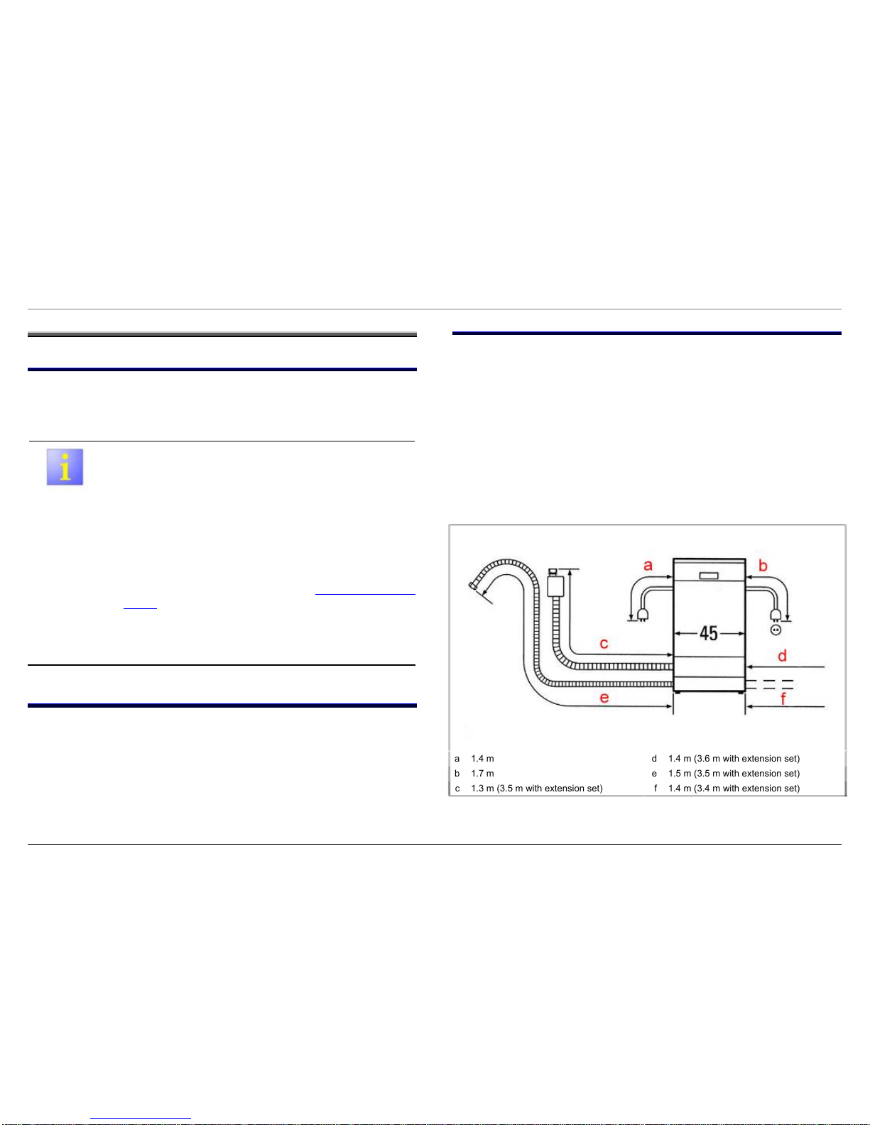
2.3 Water connection
If the appliance is connected to the drain with the standard hose
length, the max. permitted height from the floor is 90 cm. If the drainage hose is extended, a max. height of 80 cm must not be exceeded.
The water connection (3/4 inch) requires a conventional water line with
a water pressure of at least 0.5 bar (0.5 at.) (when the tap is turned
on, the water flow rate must be more than 8 l/min.). If the water
pressure is more than 10 bar (10 at.), a pressure reducing valve must
be in-stalled.
The appliances can be connected to warm water up to 60 °C. However, it is recommended to connect the appliance to cold water (better
drying and washing results).
Connection dimensions for all 45 cm dishwashers
a 1.4 m d 1.4 m (3.6 m with extension set)
b 1.7 m e 1.5 m (3.5 m with extension set)
c 1.3 m (3.5 m with extension set) f 1.4 m (3.4 m with extension set)
815_58300000120057_ara_en_d.doc – 25.05.11 Seite 5 von 60
3 OPERATION
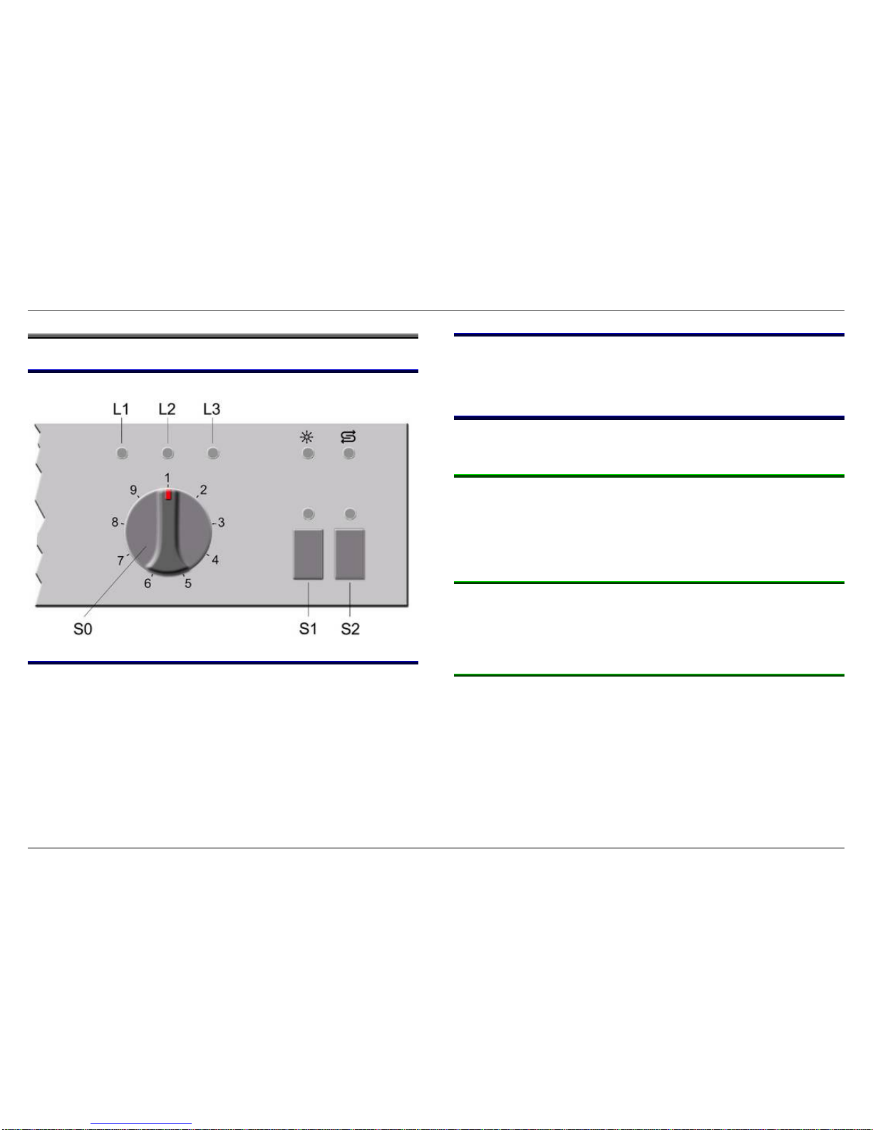
3.1 Control panel
The control panel here has maximum features
3.2 LEDs
► Tap turned off
► Active
► End
► Low salt indicator
► Low rinse aid indicator
► Additional functions
3.3 Main switch
The main switch is situated on the left side, separate from the electronics module.
3.4 Pushbuttons / Additional functions
3.4.1 Half load (optional)
The “Half Load” function reduces water consumption and the running
time. Basically this is achieved by passing over the prerinse and the
second intermediate rinse cycle.
3.4.2 Intensive drying (optional)
If intensive drying is activated, the temperature is increased by 3 K in
the final rinse to improve the drying result.
3.4.3 Reducing time (optional)
The running time of the rinse programme can be reduced with the
“Reduce time” function. To obtain optimum cleaning and drying results
at a reduced running time, the water and energy consumption is increased.

815_58300000120057_ara_en_d.doc – 25.05.11 Seite 6 von 60
3.5 Programme selector switch
3.5.1 Intensive 70°
The programme consists of a prerinse at 50°, wash cycle at 70°, two
intermediate rinse cycles, final rinse at 70° and a drying cycle. Until
the temperature is reached, rinsing occurs in the bottom basket only.
3.5.2 Normal 65°
The programme consists of a prerinse, a wash cycle at 65°, two intermediate rinse cycles, final rinse at 70° and a drying cycle.
3.5.3 ECO 50°
The programme consists of a wash cycle at 50°, one intermediate
rinse cycle, final rinse at 66° and a drying cycle. Until the temperature
is reached, rinsing occurs in the bottom basket only.
3.5.4 Gentle 40°
The programme consists of a prerinse cycle, a wash cycle at 40°, one
intermediate rinse cycle, final rinse at 55° and a drying cycle.
3.5.5 Quick 35°/45°
The programme consists of a wash cycle at 35°/45°, one intermediate
rinse cycle, final rinse at 55° without drying.
3.5.6 Prerinse
The programme consists of a prerinse only.
3.6 Setting the hardness range
Rotate the switch to position 9 (one position to the left), press and
hold down the main switch until the current setting lights up on the
display and then release the main switch. The low salt LED flashes.
Rotate the switch to set the hardness range between 0 and 2. When
the appliance is switched off, the value is saved. (Table below)
°dH °fH °Clarke mmol/l LEDs
L1 L2 L3
0 0–6 0–11 0–8 0–1.1
{ { {
1 7–14 12–25 9–18 1.2–2.5
{ {
2* 15–21 26–37 19–26 2.6–3.7
{
3 22–35 38–60 27–44 3.8–6.2
* Standard setting = 2
3.7 Reset
These appliances are reset by an additional position on the rotary
switch. As a result, the reset starts 3 sec. after the switch was moved
to this position.
The water drains for one minute and the electronics module is again
ready for a new programme.
815_58300000120057_ara_en_d.doc – 25.05.11 Seite 7 von 60
4 COMPONENTS
4.1 Module
4.1.1 Regeneration electronics
The electronics determine, in comparison with the water hardness set
on the appliance, the volume of water which is possible until the
softening system is exhausted.
The number of rinse cycles is counted. Regeneration then takes place
once the maximum possible number of rinse cycles has been
reached.
The sequence characteristics of the regeneration electronics are described under Initial start-up / Replacing the electronics.
4.1.2 Warm water detection
If the water running into the final rinse cycle is hotter than 45 °C, the
temperature in the final rinse cycle is increased to 72 °C in order to
increase the inherent heat of the dishes. The heat exchanger is not
filled.
4.1.3 Power failure
The electronics module has a power failure memory function which
ensures that the current rinse programme continues in the event of
a power failure or programme interruption.
4.1.4 Sensors
All outgoing signals from the door switch, the level switch, the NTC
sensor and the refill switches are recorded and evaluated by the
microprocessor at the required time.

815_58300000120057_ara_en_d.doc – 25.05.11 Seite 8 von 60
4.1.5 Water supply
The appliance realises that the tap is turned off if no signal is received
from the flow sensor after 30 s.
4.1.6 Consumers
The consumers such as the valves, the detergent and rinse aid dispensers and the circulation pump are actuated by triacs (see listing of
triacs). The drainage pump and the instantaneous water heater are
switched on by relays.
4.1.7 Listing the triacs
If replacing a module due to a defective triac, ensure that the actuated
component is also checked.
Before replacing a module, always start the customer
service test programme.
Before replacing a module, follow the ESD instructions.
Before replacing a module due to a defective triac,
test the actuated component.
A Dispenser actuator D Regeneration valve
B Water points (optional) E
- - -
C Filler valve
815_58300000120057_ara_en_d.doc – 25.05.11 Seite 9 von 60
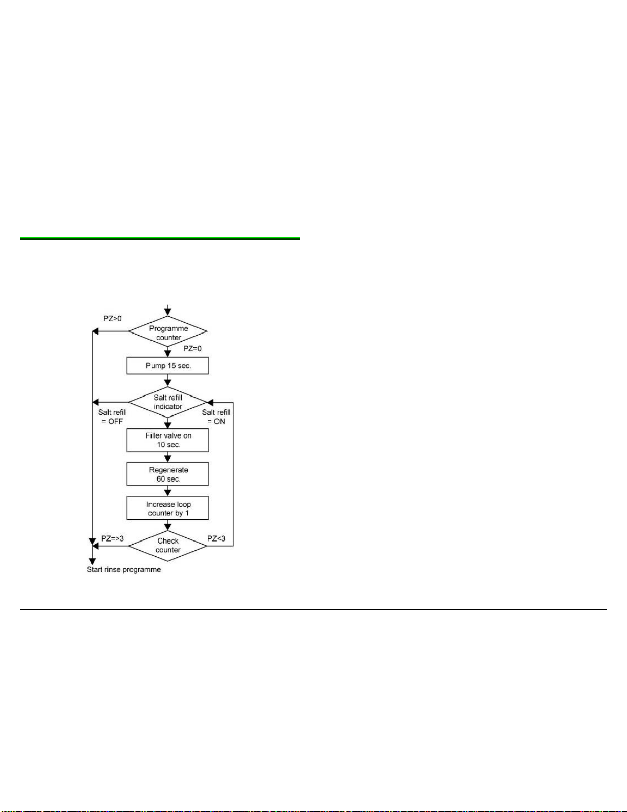
4.1.8 Initial start-up / Replacing the electronics
The following programme sequence must be taken into consideration
during the initial start-up or when replacing the electronics. (
Programme counter = 0 ! )
Programme sequence during the initial start-up without heat exchanger
815_58300000120057_ara_en_d.doc – 25.05.11 Seite 10 von 60
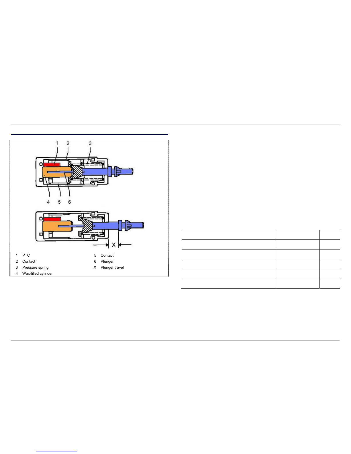
4.2 Actuator
The thermohydraulic system consists of a metal cylinder with plunger.
The cylinder is filled with a substance which expands greatly when
heated. The heat source is a PTC (positive temperature coefficient)
(1) which is in direct contact with the metal cylinder (4). A strong
pressure spring (3) returns the plunger (6) back to its original position
when the heat source is switched off.
When voltage is applied to the PTC (1), the PTC heats up and
transfers the heat to the wax-filled metal cylinder (4). The wax
expands and forces the plunger (6) out of the cylinder. The plunger (6)
transfers the mechanical movement to the release mechanism for
dispensing the detergent and rinse-aid. If the heat source is switched
off, the volume of wax is reduced by the cooling process. The
pressure spring (3) returns the plunger (6) back to its original position.
Technical specifications:
Designation Value Unit
Nominal voltage 110–240 V
Frequency 50 / 60 Hz
Resistor
0.5–1.5
kΩ
Actuation time approx. 2 min.
Reset time approx. 3 min.
1
PTC
5
Contact
2
Contact
6
Plunger
3
Pressure spring
X
Plunger travel
4
Wax-filled cylinder
815_58300000120057_ara_en_d.doc – 25.05.11 Seite 11 von 60
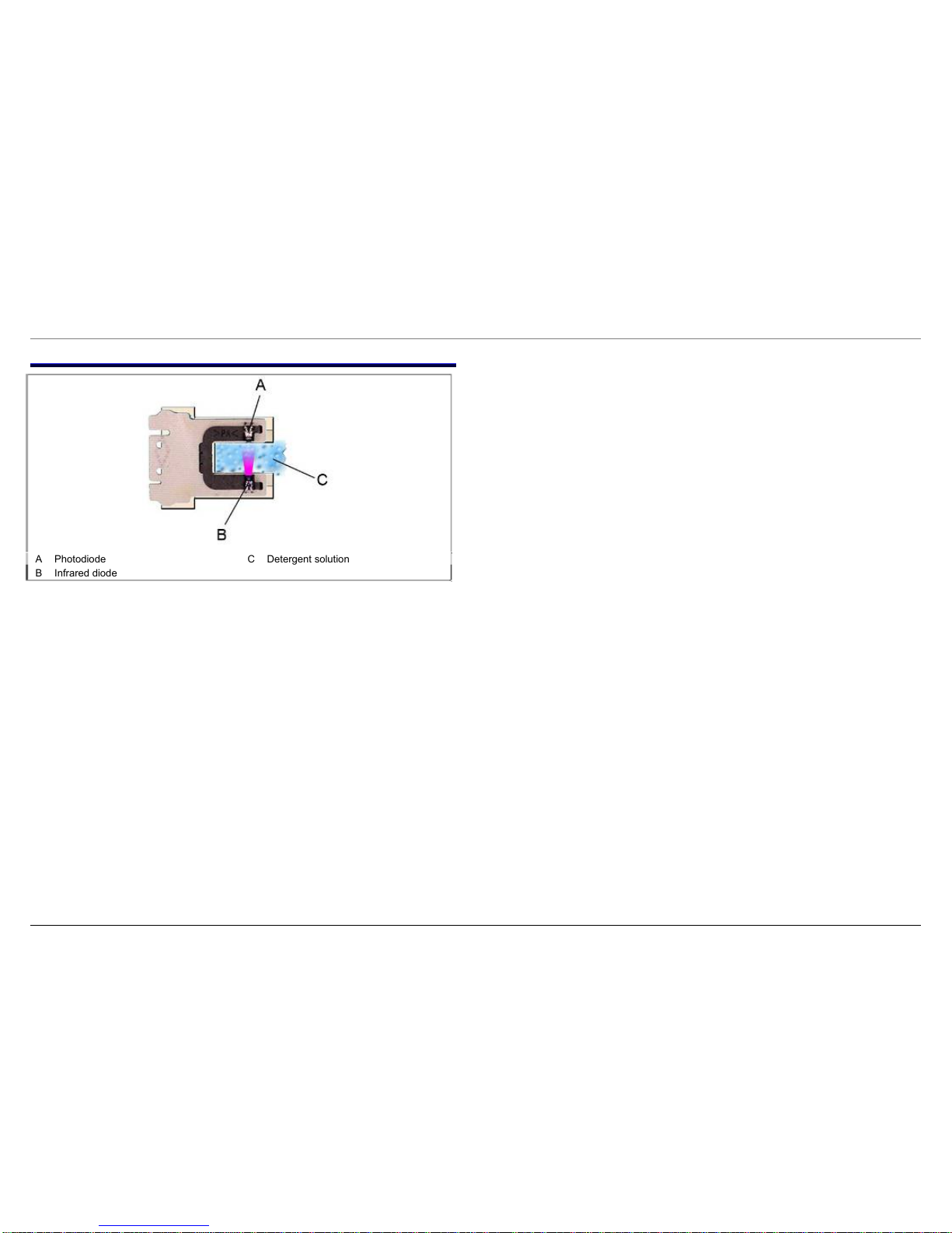
4.3 Aqua sensor (optional)
The infrared light-emitting diode (B) and the photodiode (A) are located opposite each other in a U-shaped translucent housing on a
board.
The infrared light-emitting diode (B) transmits infrared light through the
detergent solution flowing between the U-shaped housing. Depending
on the turbidity, the light-sensitive base of the photodiode becomes
conductive.
The measurement is analysed in turbidity ranges. The Aqua sensor
is active:
► in the prerinse cycle -> decision on water change before washing
► in the wash cycle -> washing temperature and rewash time
depending on turbidity range (6 turbidity ranges)
► at the end of the wash cycle via the type and number of
intermediate rinse cycles (3 turbidity ranges)
48 programme structures are possible in the automatic programme.
In each programme sequence in which the Aqua sensor is active the
sensor is also calbrated.
If the calibration is defective, a fault is written to the fault memory of
the module, the measurement is set to turbid and a maximum programme sequence occurs.
A Photodiode C Detergent solution
B Infrared diode
815_58300000120057_ara_en_d.doc – 25.05.11 Seite 12 von 60
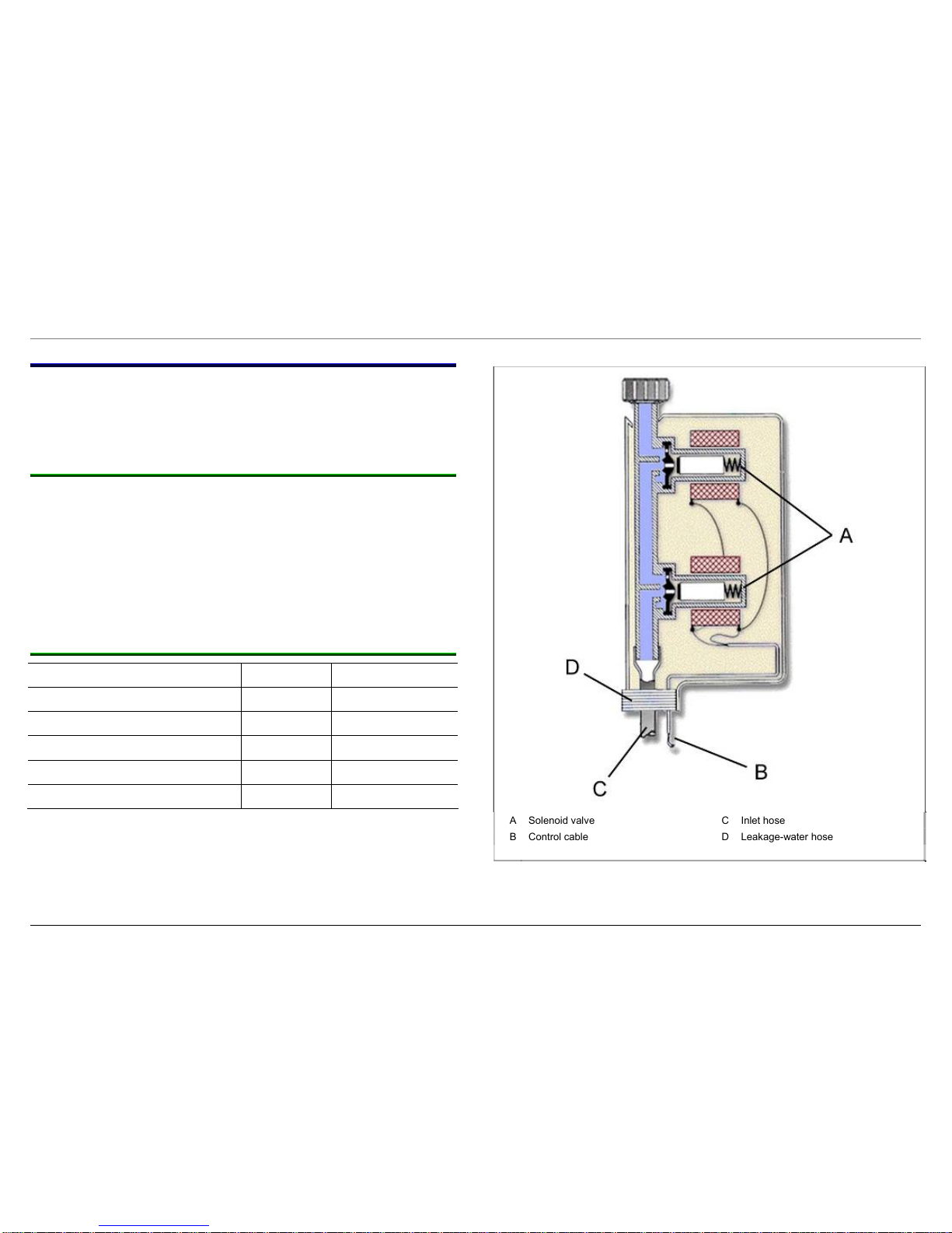
4.4 Aqua Stop valve
The Aqua Stop valve consists of two solenoid valves (A) in a row, the
filler and safety valves. These valves are actuated in parallel. There
are two filters on the screw connection for the tap. Under the filters
is the flow limiter.
4.4.1 Safety function
The safety function may be actuated via the safety level chamber
or via the float in the base pan.
The Aqua Stop valve is enclosed by a housing. The housing
is connected to the bottom pan by a leakage water hose (sleeve of the
inlet hose) (D). The inlet hose (C) and the electric control cable (B) for
the solenoid valve are situated in the leakage water hose (D). If leaks
occur in the area of the valve or inlet hose, these are conveyed into
the base pan via the leakage water hose.
4.4.2 Technical specifications
Designation Value Unit
Nominal voltage 230 - 240 V
Frequency 50 Hz
Resistor approx. 2
kΩ
Flow rate 2.75 l/min
Water pressure 0.5 - 10 bar
A
Solenoid valve
C
Inlet hose
B
Control cable
D
Leakage-water hose
815_58300000120057_ara_en_d.doc – 25.05.11 Seite 13 von 60
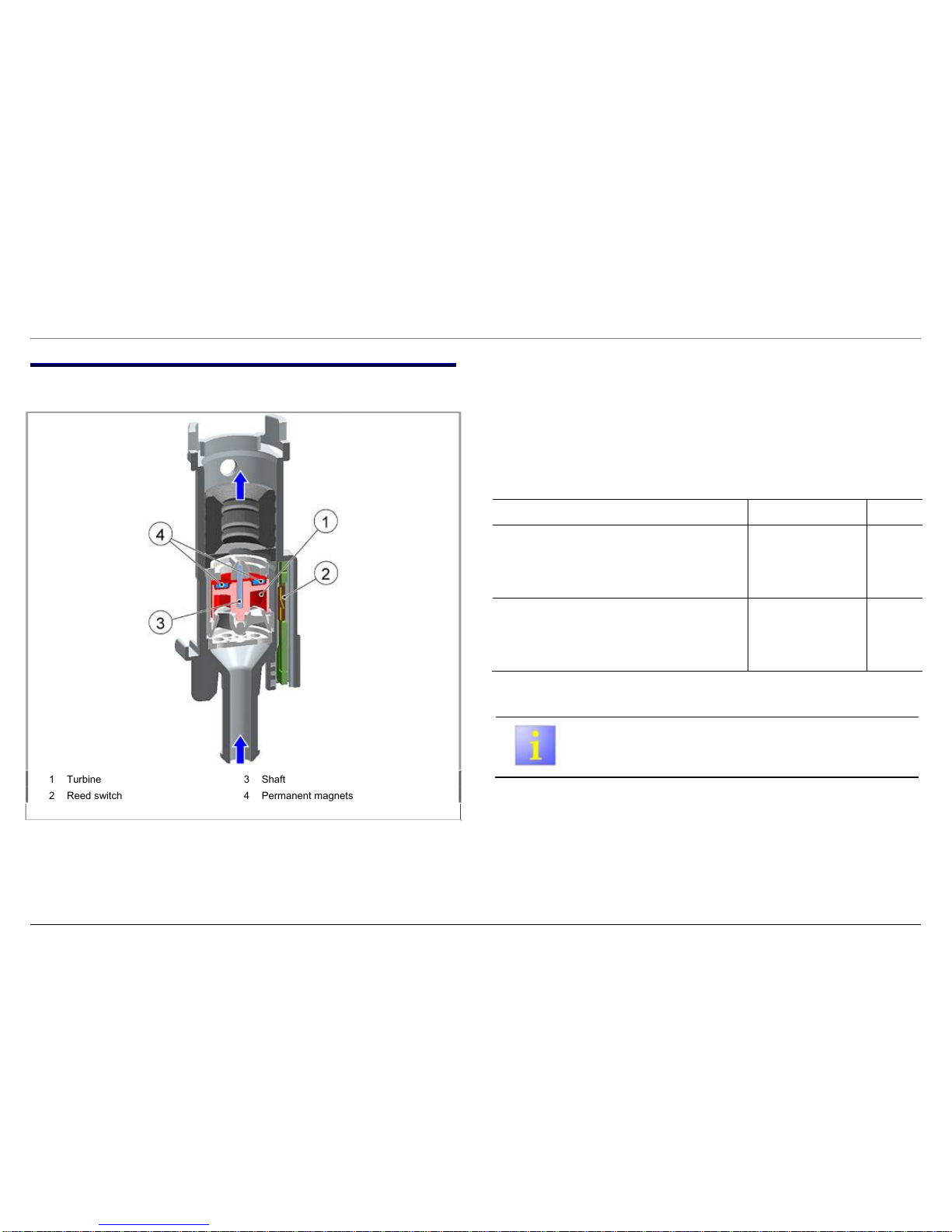
4.5 Flow sensor
The flow sensor is integrated in the water supply and registers the
amount of incoming water.
It consists of a housing, a turbine (1) with permanent magnets (4) and
a board with reed switch (2).
The water sets the turbine (1) moving. The magnets (4) attached to
the turbine (1) actuate a reed switch (2) twice for each revolution.
The generated impulses are counted by the electronics module and
cannot be measured.
Technical specifications:
Designation Value Unit
Hydraulic specifications:
Minimum flow rate
Maximum flow rate
Nominal flow rate
0.8
4.0
2.5
l/m
Electrical specifications
Output signal:
Switching current:
Rectangular
signal
max. 5
mA
Nominal output signal at 2.5 l/min flow rate: 208 impulses / litre
To facilitate replacement of the flow sensor, immerse
the hoses in hot water. (Do not use washing-up liquid
or a similar lubricant)
1
Turbine
3
Shaft
2
Reed switch
4
Permanent magnets
815_58300000120057_ara_en_d.doc – 25.05.11 Seite 14 von 60
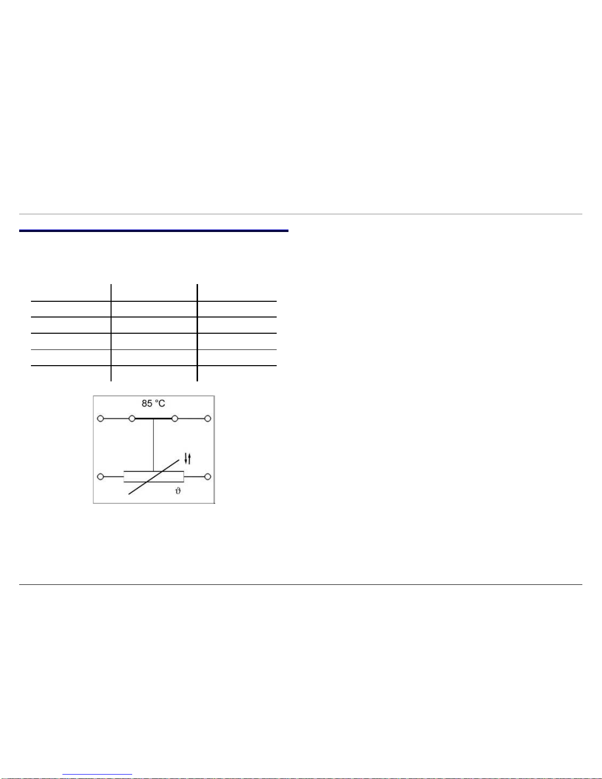
4.6 NTC
The utilised temperature safety switch (>85 °C) is combined with the
NTC sensor. If a fault occurs, the heater is switched off at a water
temperature of 85 °C (operates in switching mode).
Temperature in °C Resistance in kW Tolerance +/– °C
25 48.4 7.9
30 38.5 7.1
50 16.5 6.2
60 11.0 5.6
65 9.1 5.5
815_58300000120057_ara_en_d.doc – 25.05.11 Seite 15 von 60
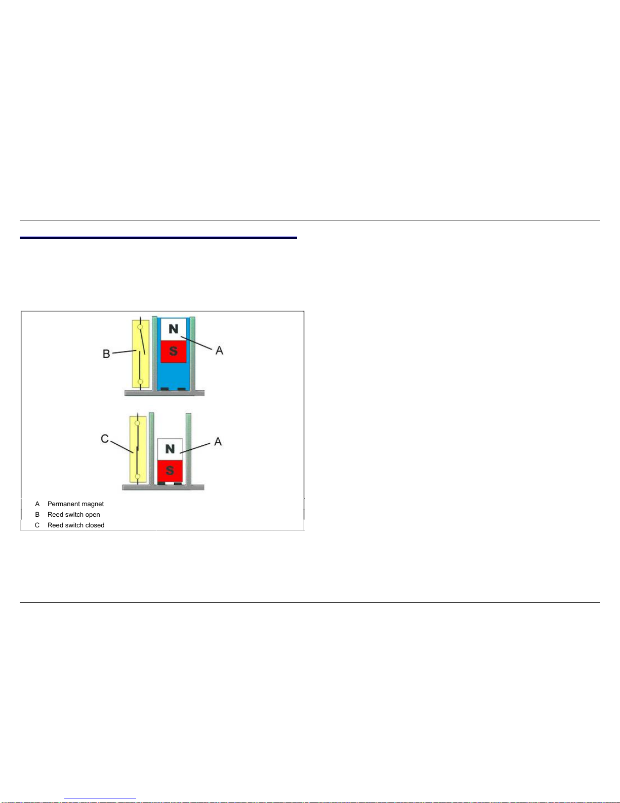
4.7 Salt and rinse-aid indicators (optional)
The dispenser contains a float with an integrated permanent magnet
(A). The magnetic field actuates a reed switch on the outside of the
dispenser. The lamps of the refill indicators in the control panel are
switched on via this reed switch.
A Permanent magnet
B Reed switch open
C Reed switch closed
815_58300000120057_ara_en_d.doc – 25.05.11 Seite 16 von 60
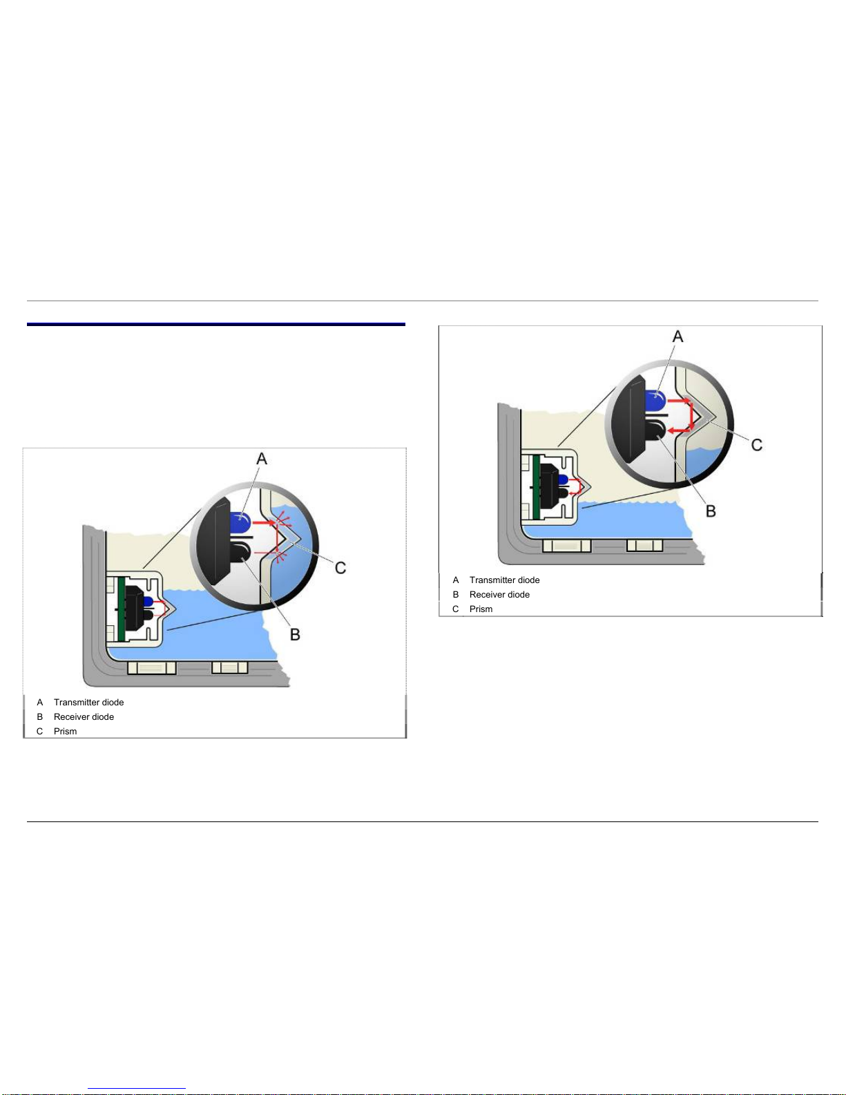
4.8 Optical low rinse-aid sensor (optional)
The optical low rinse-aid sensor consists of a transmitter diode and
a receiver diode.
A light beam is transmitted from the transmitter diode (A) to the
receiver diode (B) via a prism (C). If the dispenser is full, the light
beam in the prism is scattered. The received signal is weaker than
the transmitted one.
If the dispenser is empty, the light beam in the prism is reflected.
The received signal is the same as the transmitted signal.
The module evaluates the received signal and the refill indicator LED
is actuated.
A
Transmitter diode
B
Receiver diode
C
Prism
A
Transmitter diode
B
Receiver diode
C
Prism
815_58300000120057_ara_en_d.doc – 25.05.11 Seite 17 von 60
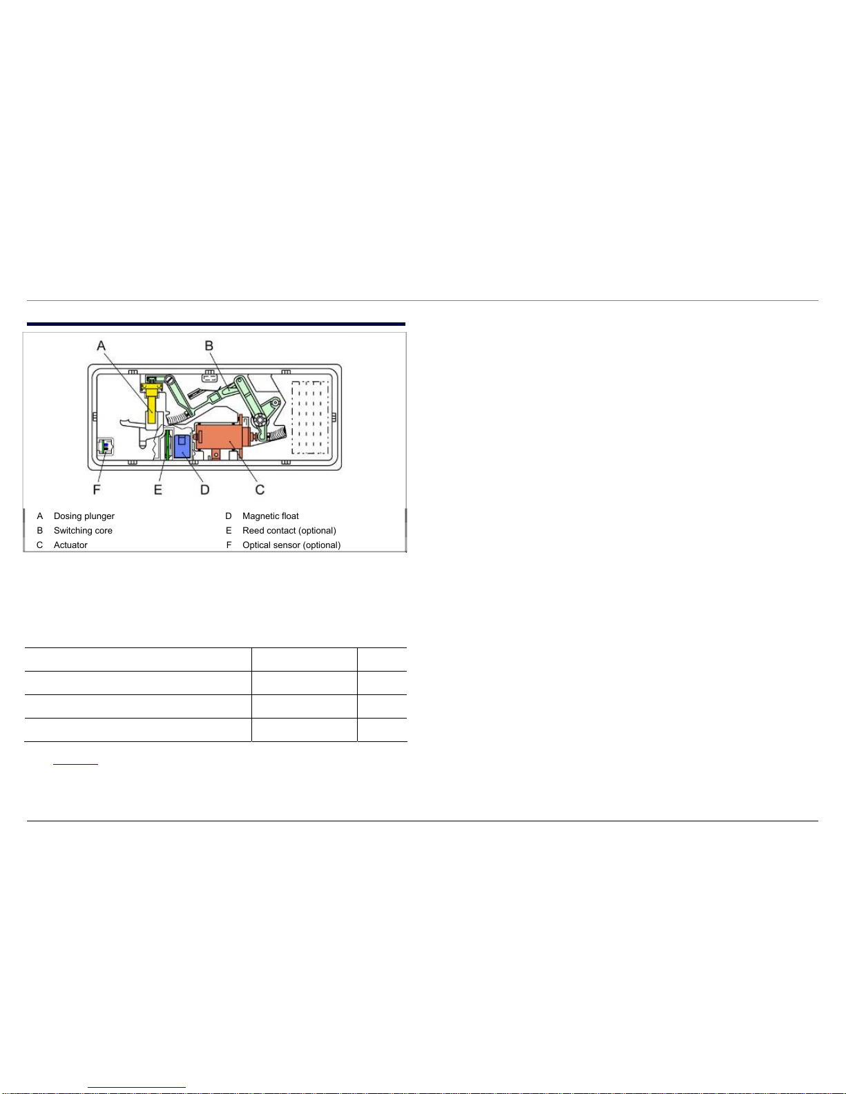
4.9 Dispenser
The release mechanism is activated by an actuator (C). When the
actuator is actuated for the first time, the detergent-dispenser cover
is opened. At the same time the release pawl engages with the
switching core (B) of the rinse-aid lever so that when the actuator (C)
is activated again, the dosing plunger (A) is lifted off the rinse aid.
Technical specifications Value Unit
Rinse aid capacity 120 ml
Setting 1–6 1 each ml
Detergent capacity max. 45 g
See Actuator for additional technical specifications.
A
Dosing plunger
D
Magnetic float
B
Switching core
E
Reed contact (optional)
C
Actuator
F
Optical sensor (optional)
815_58300000120057_ara_en_d.doc – 25.05.11 Seite 18 von 60
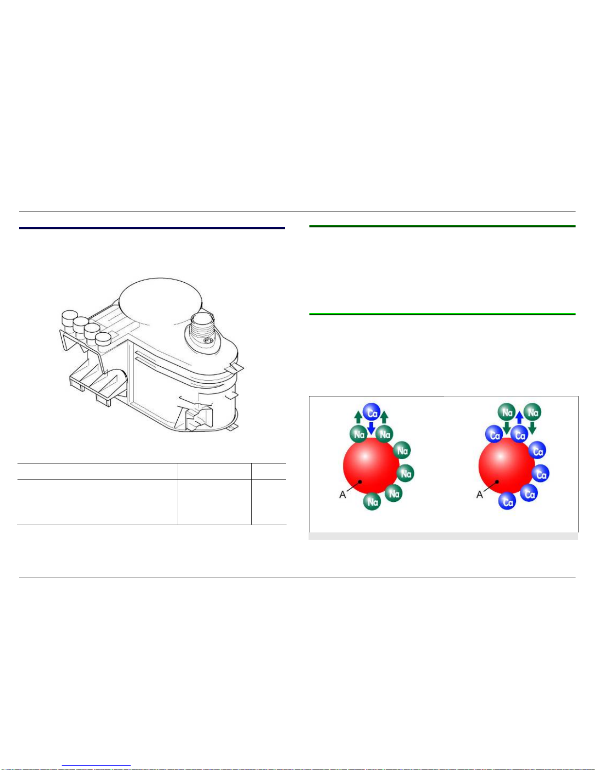
4.10 Water softening system
The water softening system (ion exchanger) is a container which
is filled with a fine-grained synthetic resin granulate. This synthetic
resin replaces calcium and magnesium ions in the water with sodium
ions situated on its surface.
Technical specifications:
Designation Value Unit
Capacity:
Fine-grained salt
Coarse-grained salt
approx. 1.3
approx. 0.9
kg
4.10.1 Water softening
The inlet water with its hardness constituents is conveyed via the
synthetic resin. Calcium and magnesium are bonded to the surface of
the exchange compound while sodium ions are released into the
water. When all sodium ions have been replaced with ions of the
hardness constituents (Fig.1), the capacity of the water softening
system is exhausted and it must be regenerated.
4.10.2 Regeneration
To make the ion exchanger functional again, a concentrated saline
solution (sodium chloride) is conveyed out of the salt dispenser
through the water softening system. On account of the large excess
the sodium ions force the calcium and magnesium ions out of the
saline solution and they attach themselves again to the exchange
compound (Fig. 2). The ion exchanger is now loaded and ready for
use again.
A Synthetic resin
Fig.1: Water softening Fig.2: Regeneration
 Loading...