

Page 1
YOUR LIFE. OUR INSPIRATION.
Power
On/Off
Delay
Start
Hours
Top
Rack
Only
Cancel
Drain
Power
Scrub
Plus
Scrub
Wash
Regular
Wash
Delicate/
Econo
Quick
Wash
Rinse
& Hold
Refill
Rinse
Agent
Cycle Countdown
Dishwasher Installation Instructions
Instructions d’installation du lave-vaisselle
Instrucciones de instalación para lavadora de platos
Use and Care Manual located on reverse side
Tourner le guide pour les instructions d’utilisation et d’entretien
Voltee el manual para encontrar las instrucciones de uso y cuidado
9000060333 (8503)
Page 2

Page 3
Table of Contents / Important Instructions
Table of Contents
IMPORTANT INSTRUCTIONS ................................ 1
Tools Needed ........................................................... 2
Materials Needed .....................................................2
Materials Supplied ...................................................3
Enclosure Preparation ............................................. 4
Electrical Preparation .............................................. 5
Plumbing Preparation ........................................... 6-7
Dishwasher Preparation ........................................ 7-8
Door Panel Installation .............................................9
Important Safety Instructions
WARNING
To avoid possible injury or property damage,
OBSERVE ALL WARNINGS AND CAUTIONS.
These instructions are intended for use by
qualified installers only.
The dishwasher must be installed by a qualified
service technician.
• In addition to these instructions, the dishwasher
shall be installed to meet all electrical and
plumbing codes and ordinances (both national and
local).
Read these installation instructions completely
and follow them carefully. They will save you time
and effort and help to ensure safety and optimum
dishwasher performance.
CAUTION
If the dishwasher is installed in a location that
experiences freezing temperatures (e.g., in a
holiday home), you must drain all the water
from the dishwasher’s interior. Water system
ruptures that occur as a result of freezing are
not covered by warranty.
Placing the Dishwasher ......................................... 10
Securing the Dishwasher ....................................... 10
Drain Hose Connection .......................................... 11
Hot Water Connection ............................................12
Electrical Connection........................................ 13-14
Door Tension Adjustment ....................................... 14
Base and Toe Panel .......................................... 14-15
Final Instructions ................................................... 15
Customer Service .................................................. 16
IMPORTANT
• The dishwasher drain hose must be installed
with a portion of it at least 20” (508mm) off the
cabinet floor; otherwise the dishwasher may not
drain properly.
• This dishwasher is intended for residential use
only, and should not be used in commercial food
service establishments.
• NEW INSTALLATION - If the dishwasher is a
new installation, most of the work must be done
before the dishwasher is moved into place.
• REPLACEMENT - If the dishwasher is replacing
another dishwasher, check the existing
dishwasher connections for compatibility with
the new dishwasher, and replace parts as
necessary.
Inspect the Dishwasher
After unpacking the dishwasher and prior to
installation, thoroughly inspect the dishwasher for
possible freight or cosmetic damage. Report any
damage immediately. Cosmetic defects must be
reported within 5 days of installation.
NOTE: Do not discard any bags or items that come
with the original package until after the entire
installation has been completed.
1
Page 4

TOOLS NEEDED
Tools and Materials Needed
Hammer Hole Saw
Tape Measure
Wire Cutter
Slot Screwdriver
Wire Stripper
Phillips Screwdriver
Drill
MATERIALS NEEDED
(Additional materials may be required to comply with local codes.)
Pipe Wrench
Adjustable Wrench
Torx Screwdriver
Level
Electrical Supply Cable - Minimum #14 AWG, 2 conductor, 1 ground, insulated copper
conductors rated 75°C or higher.
Hot Water Supply Line - Minimum 3/8” O.D. copper tubing or metal braided dishwasher
supply line.
Shut-off valve and fittings appropriate for hot water supply line (copper tubing/
compression fitting, or braided hose).
90° elbow with 3/8” N.P.T. male threads on one leg, and sized to fit your water supply
line (copper tubing/compression fitting, or braided hose) on the other leg.
Teflon tape or other pipe thread compound to seal plumbing connections.
UL listed conduit connector or strain relief.
2
Page 5
Materials Supplied
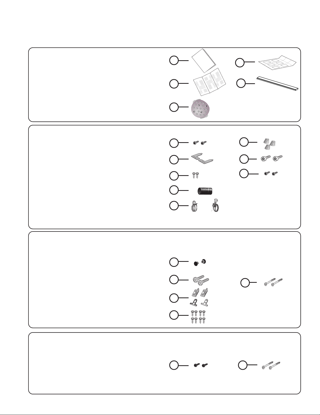
MATERIALS SUPPLIED
Accessory Parts Supplied
Accessory parts for your dishwasher come in one or more plastic bags that are outlined below.
NOTE: Make sure you save all the bags until you have completed your installation.
Manual Set Bag
A Manual Set Bag is provided with each dishwasher
and includes:
A Use & Care Instructions and Installation
Instructions (both manuals may be included
in a single “flip-style” book
B Quick Reference Guide (select models)
C Extra Tall Item Sprinkler
D SHI and SHV Installation Template (SHI and SHV
models only)
E White Cotton Insulation Strip (SHY66 and
SHX99A models only)
Dishwasher Installation Kit
A Dishwasher Installation Kit is provided with each
dishwasher and includes:
F Toe Panel Screws (2 black machine screws)
G Counter Top Mounting Brackets (2 “L” shaped
metal brackets)
H Mounting Bracket Screws (2 silver wood screws)
I Rubber Drain Hose Adaptor (1 black rubber tube)
J Hose Clamps ( 1 silver spring clamp to use to
attach the rubber adaptor to the Drain Hose and 1
gold screw clamp to attach the rubber adaptor to
the plumbing)
K Wire Nuts (3 for electrical connection)
L Electrical Junction Box Screws (2 silver
machine screws)
M Leg Leveler Locking Screws (2 gold coarse
threaded screws)
A
B
C
F
G
H
I
J
D
E
K
L
M
SHI/SHV Door Panel Installation Kit
A Door Panel Installation Kit is provided with select
dishwashers that use a custom wood door panel and
includes:
N Plastic Caps (2)
O Spring Tension Screws (2 larger silver machine
screws used to adjust the door springs to accommodate doors of different weights)
P Door Mounting Brackets (2 gold metal brackets
and 2 white plastic brackets used to mount the
custom door)
Q Door Mounting Bracket Screws (8 silver wood
screws)
R Door Mounting Screws (2 long silver screws used
to attach the door)
Toe Panel Installation Kit
A Toe Panel Installation Kit is provided with select
dishwashers (SHY66C/SHX99A) that use a special toe
panel and includes:
S Toe Panel Screws (2 black screws used to attach
the metal Toe Panel)
T Black Plastic Base Access Panel Screws (2 long
silver screws used to attach the Black plastic
Base Access Panel to the dishwasher.
N
O
P
Q
S T
R
3
Page 6
Enclosure Preparation
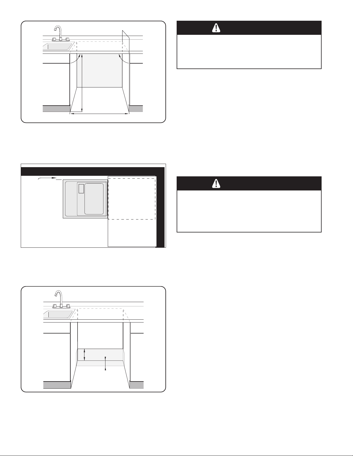
Check
clearance
between
dishwasher
door and wall
34"
(864mm)
minimum
23-5/8" – 24-1/4" (600–616 mm)
Figure 1
Countertop
23-9/16"
(598mm)
90 90
WARNING
Electrical Shock Hazard
To avoid electrical shock, make sure the water
supply and electrical supply are shut off before
installation or service.
ENCLOSURE PREPARATION
NOTE: This dishwasher is designed to be enclosed on the
top and both sides by standard residential kitchen
cabinetry.
Select a location as close to the sink as possible for
easy access to water supply and drain lines.
For proper dishwasher operation and appearance, ensure
that the enclosure is square and has the dimensions
shown in Figure 1.
If the dishwasher is to be installed in a corner, make sure
that there is adequate clearance to open the door. See
Figure 2.
WARNING
Electrical Shock/Fire Hazard
To avoid electric shock or fire, do not allow the
electrical and water supply lines to touch.
Separate channels are provided under the
dishwasher (see page 10).
Figure 2
3-1/2"
(89mm)
Figure 3
1-5/16"
(33mm)
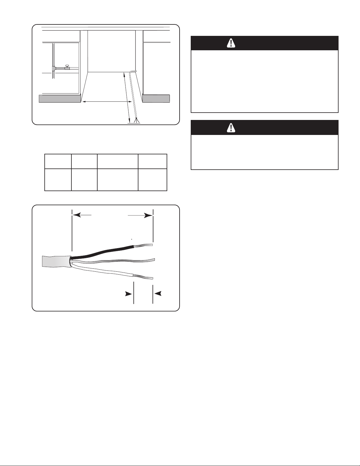
If the enclosure requires openings for the electrical supply
cable, hot water supply line, and dishwasher drain hose,
place them within the dimensions shown by the shaded
area of Figure 3 to avoid interference with the dishwasher
frame or other components. Make the openings for the
electrical supply cable and hot water supply line 1”
(25.4mm) diameter. Make the opening for the dishwasher
drain hose 1-1/4” (32mm) diameter. If the openings are
made through wood, sand them smooth. If the openings
are made through metal, make them large enough to
accommodate grommets or other protective sheaths with
inside diameters of 1” (25.4mm) for the electrical supply
cable and the hot water supply line, and 1-1/4” (32mm) for
the dishwasher drain hose.
4
Page 7
(762mm)
3/8" - 1/2"
( 8mm - 13mm)
3" - 4"
( 75mm - 100mm)
21"
(533mm)
30"
Electrical Preparation
ELECTRICAL PREPARATION
WARNING
Electrical Shock Hazard
To avoid electrical shock, do not work on an
energized circuit. Doing so could result in serious
injury or death. Only qualified electricians should
perform electrical work. Do not attempt any work
on the dishwasher electric supply circuit until you
are certain the circuit is
de-energized.
Figure 4
Dishwasher Electrical Rating
stloVztreHserepmAsttaW
0210651
Figure 5
WARNING
Fire Hazard
To avoid a fire hazard, make sure electrical work
is properly installed. Only qualified electricians
should perform electrical work.
054,1
)xam(
Electrical Supply
The customer has the responsibility of ensuring that the
dishwasher electrical installation is in compliance with all
national and local electrical codes and ordinances. The
dishwasher is designed for an electrical supply of 120V,
60 Hz, AC, connected to a dishwasher-dedicated,
properly grounded electrical circuit with a fuse or breaker
rated for 15 amps. Electrical supply conductors shall be a
minimum #14 AWG copper wire rated at 75°C or higher.
Regardless of where the electrical supply cable enters the
enclosure (following the guidelines on page 8), position
the cable 21” (533mm) from the enclosure’s left side, as
shown in Figure 4. Extend the cable 30” (762mm) from
the enclosure’s back, as shown in Figure 4.
Remove 3” - 4” (75mm - 100mm) of the cable’s outer
casing, as shown in Figure 5, then remove 3/8” - 1/2”
(9 - 13mm) of insulation from each wire, as shown in
Figure 5.
5
Page 8
14"
(355mm)
Shut off
Valve
Hot Water
Supply
Line
Plumbing Preparation
PLUMBING PREPARATION
To avoid being scalded, do not perform any work
on a charged hot water line. Serious injury could
result. Only qualified plumbers should perform
plumbing work. Do not attempt any work on the
dishwasher hot water supply plumbing until you
are certain the hot water supply is shut off.
WARNING
Scald Hazard
Figure 6
CAUTION
Temperatures required for soldering and sweating
will damage the dishwasher’s base and water inlet
valve. If plumbing lines are to be soldered or
sweated, keep the heat source at least 6 inches
(152.4 mm) away from the dishwasher’s base and
water inlet valve.
Hot Water Supply
The hot water heater should be set to deliver
approximately 120° F (49° C) water to the dishwasher.
Water that is too hot can cause some detergents to lose
effectiveness. Lower water temperatures will increase run
times. The hot water supply pressure must be between
15 - 145 psi (1 - 10 bars).
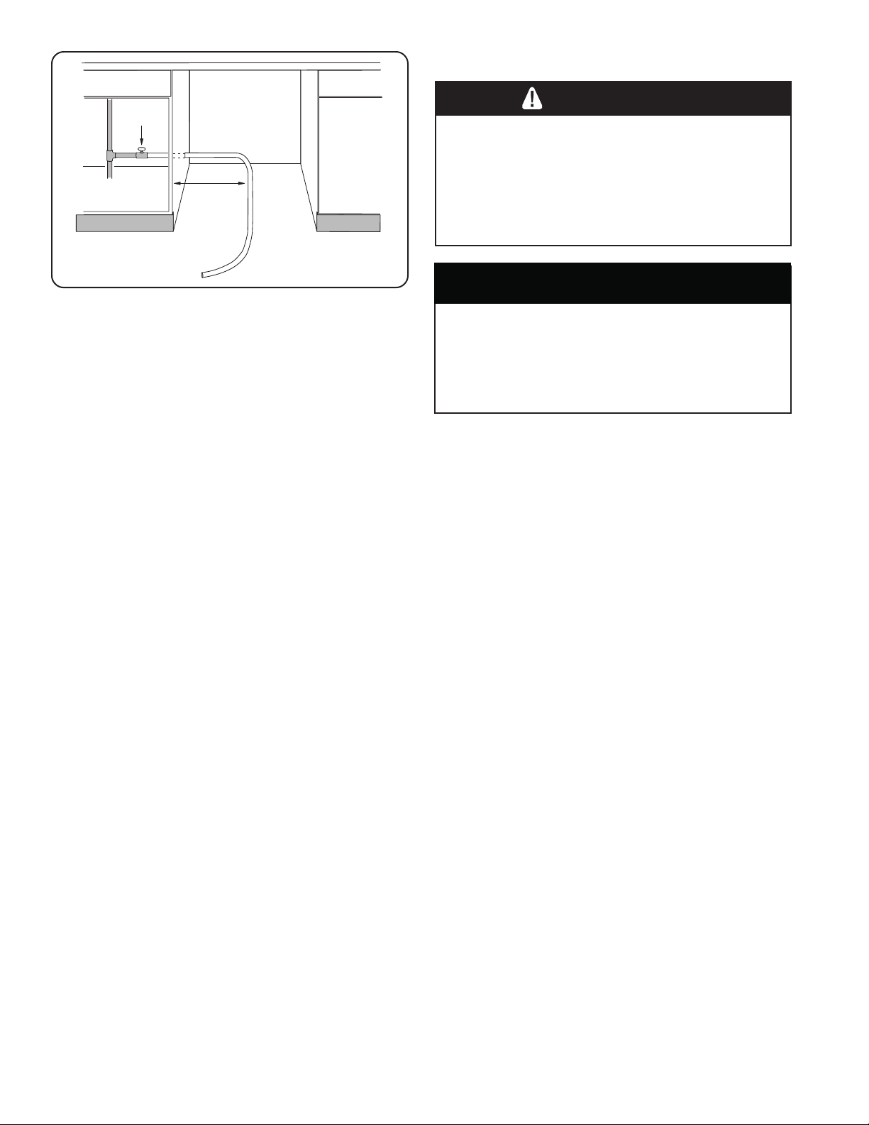
Hot Water Supply Plumbing
Install an easily accessible shut-off valve (not supplied) in
the hot water supply line, as shown in Figure 6. All solder
connections must be made before the water line is
connected to the dishwasher’s water inlet valve. Water
may also be supplied to the dishwasher by using a
braided hose line. Check with your local plumbing supply
sources for the proper hose and 90° elbow fitting.
6
NOTE: Regardless of where the hot water supply line
enters the enclosure, position the line 14” (355mm) from
the enclosure’s left side, as shown in Figure 6.
NOTE: Decide whether braided hose or copper tubing will
be used for the hot water supply plumbing, and purchase
the correct type of hot water supply shut-off valve, 90°
elbow, and necessary fittings for the hot water supply
plumbing.
Page 9

Plumbing Preparation/ Dishwasher Preparation
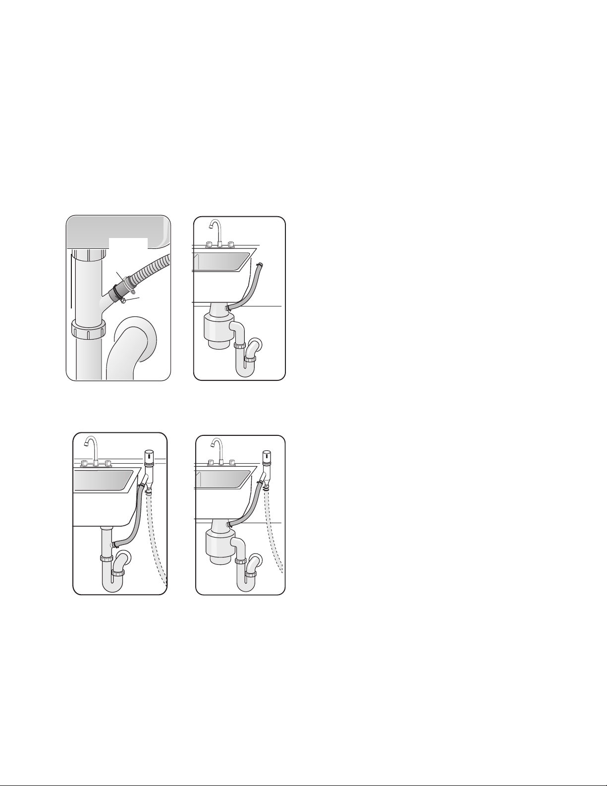
Y-branch
Tailpiece
Figure 7
Air Gap
Figure 8
PLUMBING PREPARATION (continued)
Drain Plumbing
Under Sink Drain Connection
If the dishwasher is to drain either directly into the
household drain plumbing or through an air gap, install a
y-branch tailpiece under the sink as shown in Figure 7.
Installing an Air Gap
If local ordinances require an air gap, as shown in
Figure 8, install it according to the manufacturer’s
instructions.
Disposer
Make sure to remove the disposer’s dishwasher drain
connection plug before connecting the dishwasher drain
hose. See Figure 9.
DISHWASHER PREPARATION
Dishwasher preparation involves four tasks:
• Installing the Mounting Brackets
• Removing the Toe Panel
• Installing the 90° elbow fitting
• Junction Box Preparation
Installing the Countertop Mounting Brackets
Remove
plug
Figure 9
Top Mount
Side Mount
CAUTION
Before installing the supplied countertop mounting
brackets, decide which method of securing the
dishwasher into its enclosure will be used. Once
the mounting brackets are installed on the dishwasher, removing them is difficult and will damage
the mounting brackets and the dishwasher.
The dishwasher can be secured into its enclosure in two
ways:
1 Top Mount is used for countertops made of wood or
other materials that can easily drilled. Orient the
mounting brackets as shown in Figure 10, and
position the two small tabs on the mounting brackets
over the two slots on the dishwasher’s front corners.
Push the mounting brackets down firmly to insert the
tabs into the slots.
2 Side Mount is used for countertops made of marble,
granite, or other very hard materials that cannot be
easily drilled. Bend the mounting brackets along the
small holes and in the same direction as the two small
tabs. Orient the mounting brackets as shown in Figure
10, and position the two small tabs on the mounting
brackets over the two slots on the dishwasher’s front
corners. Push the mounting brackets down firmly to
insert the tabs into the slots.
Figure 10
WARNING
Tip Over Hazard
To avoid a tip over hazard, do not use the
dishwasher until it is completely installed. When
opening the door on an uninstalled dishwasher,
carefully open the door while supporting the rear
of the unit. Failure to follow this warning can
result in serious injury.
7
Page 10

Figure 11
Toe
Plastic Base
Access Panel
Dishwasher Preparation
DISHWASHER PREPARATION (continued)
Removing the Toe Panel
Regular Toe Panel
The toe panel is loosely attached with tape. Remove the
tape and pull the toe panel away from the dishwasher. Set
the toe panel aside. It will be reinstalled later.
SHY66C and SHX99A Plastic Base Access Panel and
Toe Panel
The plastic base access panel (select models SHY66C/
SHX99A only) and toe panel are in place on the
dishwasher, but are not attached. Remove the toe panel
first, as shown in Figure 11, then remove the plastic
base access panel, as shown in Figure 11.
Installing the 90° Elbow Fitting
NOTE: The 90° elbow fitting is not supplied with the
dishwasher, and must be purchased separately. If the
dishwasher’s hot water supply line is to be copper tubing,
make certain the elbow has a compression fitting.
Apply Teflon tape or other pipe sealant when required.
Orient the hot water supply connection leg of the elbow
toward the channel opening in the dishwasher base. See
Figure 12.
Figure 12
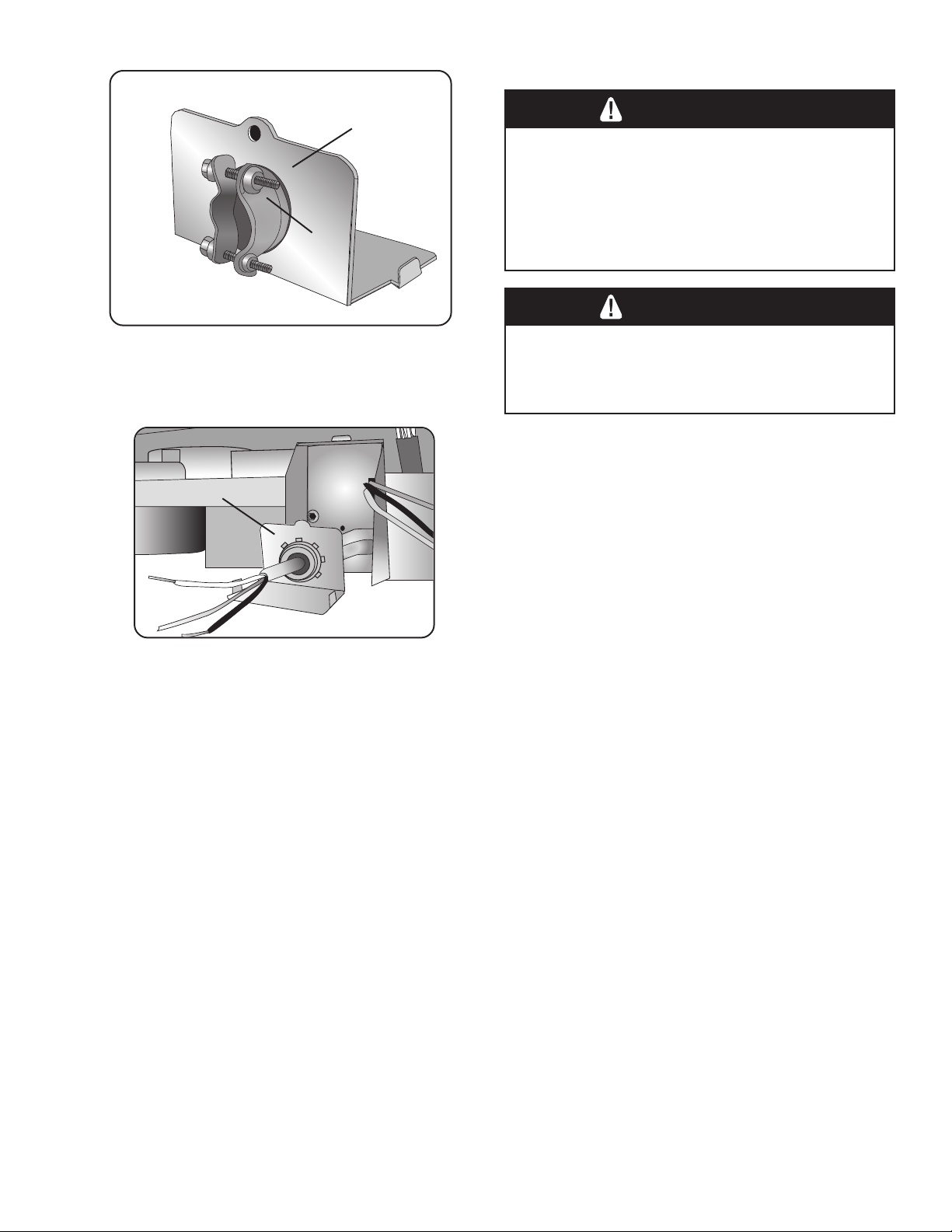
Junction Box Preparation
1 Remove junction box cover (see Figure 13) by lifting
the junction box cover up and off.
2 Remove the strain relief plate by removing the screw
at the back of the junction box, as shown in Figure
14 and sliding the strain relief plate out.
3 Set the junction box cover, strain relief plate, and
screw aside. They will be reinstalled later.
Remove
Screw
Junction
Box
Cover
Figure 13
X
Figure 14
8
Page 11
25”
(636 mm)
Door Panel Installation
1/4” max.
(6 mm)
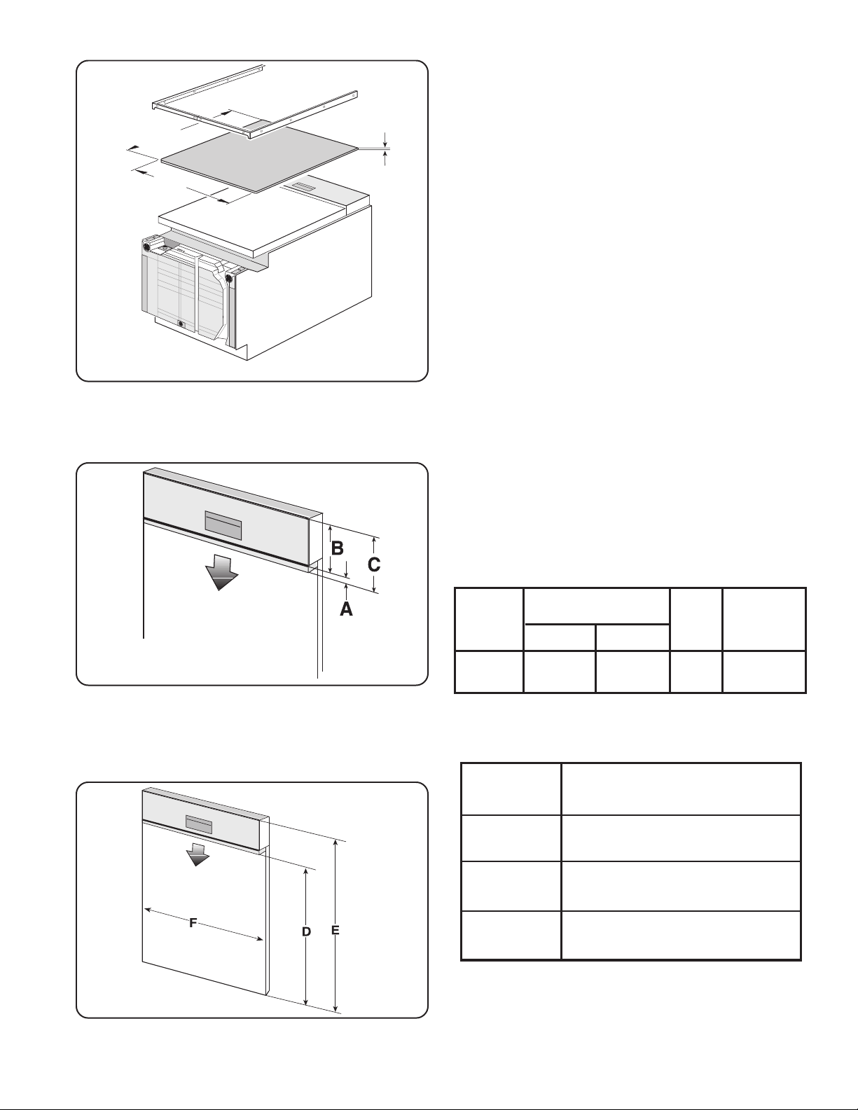
DOOR PANEL INSTALLATION
SHU Models - Accessory Panel Installation
If you have an SHU model and have ordered an accessory panel kit, install the panel prior to sliding the dishwasher into place. The panel dimensions are shown in
Figure 15.
23-1/16”
(586 mm)
Figure 15
SHI Models - Panel Installation
SHI models come with additional mounting hardware and
a template sheet with installation instructions. The stainless steel models of the SHI series also come with two
extension pieces. The extension pieces are used to
match the control panel height (Figure 16, “B” dimension)
to the horizontal drawer line of the cabinets, and must be
installed as shown in on the template sheet. The standard
piece is used for drawer heights up to 6” (152mm); the
long piece is used for drawer heights greater than 6”
(152mm) but 6-7/16” (164mm) or less. If your drawers are
taller than 6-7/16”, you can either slide the extension
piece in as far as it will go, or remove it and fit the door
panel directly below the control panel.
SHI/SHV Models - Panel Installation
SHV models come with additional mounting hardware and
a template sheet that will show you how to mount the
panel. One side of the template shows how to mount a
one piece panel; the other side shows how to mount a two
piece panel. Decide which type of installation you want
before proceeding with the installation.
Figure 16
Fig. 16
Dimension
SHI Only
Fig. 17
Dimension
D (SHI)
E
(SHI & SHV)
F
(SHI & SHV)
Extension “A”
Max. - Min.
Standard
5/16 - 11/16”
(8-18mm)
Long
11/16 - 1 1/8”
(18 - 29mm)
Panel Dimension
20 11/16” - 25”
(526mm - 635mm)
27 3/16” - 30 5/16”
(690mm - 770mm)
23 3/16” - 23 3/8”
(589mm - 594mm)
“B” “C”
Max.-Min.
5 5/16”
(135mm)
5 5/8 - 6 7/16”
(143 - 164mm)
Figure 17
9
Page 12
14"
(355mm)
21"
(533mm)
Figure 18
Placing the Dishwasher/ Securing the Dishwasher
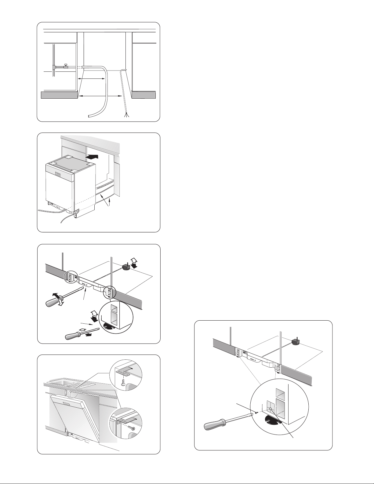
PLACING THE DISHWASHER
1 Straighten and position the hot water supply line and
the electrical supply cable as shown in Figure 18 so
that they will align with their channels under the
dishwasher base.
2 Position the dishwasher close enough to the enclosure
so that you can run the dishwasher drain hose to the
under sink drain connection. Make certain that the hot
water supply line and the electrical supply cable are in
their channels under the dishwasher base, as shown in
Figure 19.
3 Slide the dishwasher into the opening making sure that
the hot water supply line and the electrical supply
cable stay in their proper channels.
4 Make sure the dishwasher is level. Adjust the rear
leveler by turning the center screw at the front of the
dishwasher, as shown in Figure 20a. Turning the screw
clockwise raises the rear of the dishwasher. Adjust the
front levelers by turning them with a screwdriver, as
shown in Figure 20b. Turning the levelers to the right
raises the dishwasher. If additional height is needed,
shims may be added under the leveler feet.
Figure 19
a
b
Figure 20
Top Mount
Hot Water Supply Line
and Electrical Supply
Cable Position in
Channels
SECURING THE DISHWASHER
1 Drive the mounting screws through the holes in the
mounting brackets as shown in Figure 21 for Top
Mount or Side Mount.
2 After the unit is installed in the enclosure, leveled and
secured, lock the two front leg levelers in place by
driving the enclosed leg leveler locking screws into
each screw boss located in front of the levelers. See
Figure 22.
3 Tighten screws until they are flush with the surface of
the bosses.
10
Figure 21
Side Mount
Leg
Leveler
Locking
Screw
Screw
Boss
Figure 22
Page 13
Silver
Spring
Clamp
Gold
Screw
Clamp
Drain Hose Connection
Installation of the Rubber Drain Hose
Adaptor
1 Obtain the Rubber Drain Hose Adaptor and the two
hose clamps from the Dishwasher Installation Kit.
2 On one outside end of the Rubber Drain Hose Adapter
is a raised groove. Insert the drain hose into the end
without the raised groove. Be sure to fully insert the
drain hose.
3 Secure the connection with the Silver Spring Clamp.
4 Use the Gold Screw Clamp to attach the Rubber Drain
Hose Adaptor to the house plumbing.
Connecting the Drain Hose to the
Household Plumbing
The dishwasher drain hose may be connected to the drain
plumbing in one of four ways:
1 Directly to the under-sink dishwasher drain connection,
as shown in Figure 23.
2 Directly to a disposer dishwasher drain connection, as
shown in Figure 24.
3 To the under-sink dishwasher drain connection through
an air gap, as shown in Figure 25.
4 To a disposer dishwasher drain connection through an
air gap, as shown on Figure 26.
Figure 23 Figure 24
Figure 25 Figure 26
Information on installing air gaps and disposers can be
found in the Plumbing Preparation section of this
manual.
NOTE: If the dishwasher drain hose is to be connected to
a disposer dishwasher drain connection, remove the plug
from the disposer’s dishwasher drain connection.
Use the supplied Rubber Drain Hose Adaptor and Drain
Hose Clamps to connect the dishwasher drain hose to the
plumbing drain connection. Use the spring clamp to
secure the Rubber Drain Hose Adaptor to the dishwasher
drain hose. Use the screw clamp to secure the Rubber
Drain Hose Adaptor to the plumbing drain connection.
The dishwasher drain hose must have one place along its
length that is securely attached 20 inches above the
cabinet floor.
11
Page 14

Hot Water Connection
HOT WATER CONNECTION
To avoid being scalded, do not perform any work
on a charged hot water line. Serious injury could
result. Only qualified plumbers should perform
plumbing work. Do not attempt any work on the
dishwasher hot water supply plumbing until you
are certain the hot water supply is shut off.
NOTE: Make certain that the correct 90° elbow fitting (not
supplied) for the hot water supply line has been purchased and installed on the dishwasher as described in
the Dishwasher Preparation section of this manual.
The hot water supply line may be connected to the
dishwasher in one of two ways:
1 With braided hose.
2 With copper tubing.
Braided Dishwasher Supply Hose
After connections are made turn on the hot water supply
to check for leaks.
NOTE: Braided dishwasher supply hoses can also be
used to extend pre-existing dishwasher water supply
lines.
WARNING
Scald Hazard
Copper Tubing
CAUTION
Temperatures required for soldering and sweating
will damage the dishwasher’s water inlet valve. If
plumbing lines are to be soldered or sweated,
keep the heat source at least 6 inches (152.4 mm)
away from the dishwasher’s water inlet valve.
• If using a solder joint instead of a compression fitting,
be sure to make all solder connections before
connecting the water line to the dishwasher.
• Make certain there are no sharp bends or kinks in the
water line that might restrict water flow.
• Be sure to use pipe thread compound or Teflon tape to
seal the connection when required.
• Before connecting the copper hot water supply line to
the dishwasher, flush it with hot water to clear any
foreign material.
• Turn on the water supply to check for leaks after
making connections.
NOTE: Do not use pipe sealant on compression fittings.
12
Page 15
Electrical Connection
ELECTRICAL CONNECTION
Figure 27
Strain Relief Plate
Figure 28
Strain
Relief
Plate
Strain Relief
(not supplied)
WARNING
Electrical Shock Hazard
To avoid electrical shock, do not work on an
energized circuit. Doing so could result in serious
injury or death. Only qualified electricians should
perform electrical work. Do not attempt any work
on the dishwasher electric supply circuit until you
are certain the circuit is de-energized.
WARNING
Fire Hazard
To avoid a fire hazard, make sure electrical work
is properly installed. Only qualified electricians
should perform electrical work.
Grounding Instructions
The dishwasher must be properly grounded before
operating. This appliance must be connected to a
grounded metal permanent wiring system, or an
equipment grounding conductor must be run with the
circuit conductors and connected to the equipment
grounding terminal or lead on the dishwasher. Make sure
that the dishwasher is connected to a suitable ground in
compliance with all local codes or, in the absence of a
local code, with the NATIONAL ELECTRICAL CODE in
the United States or the CANADIAN ELECTRIC CODE
C22.1- latest edition in Canada as well as any provincial/
state or municipal or local codes that apply.
1 Retrieve the strain relief plate, and install a strain relief
(not supplied) into the opening on the strain relief plate.
NOTE: Orient the strain relief as shown in Figure 27.
2 Pass the electrical supply cable through the strain
relief, as shown in Figure 28. Leave 3 - 4 inches of
insulated wire extending through the strain relief plate.
3 Tighten the strain relief screws.
4 Slide the strain relief plate into the junction box, and
secure it to the junction box with the supplied screw.
13
Page 16

Electrical Connection/ Door Tension Adjustment/ Base and Toe Panel
ELECTRICAL CONNECTION (continued)
WARNING
Fire Hazard
To avoid a fire hazard, make sure there are no
loose electrical connections. Make sure all
1/8”
3mm
Figure 29
electrical connections are properly made.
• Do not pre-twist the wires before connecting them
with wire nuts.
• Extend the dishwasher’s stranded wires 1/8” (3mm)
beyond the power supply cable’s solid wires, as
shown in Figure 29.
5 Using the supplied wire nuts, connect the electrical
supply wires to the dishwasher’s wires, black to black,
white to white, and green or bare. Make certain that
the insulated wires show no bare wire from the
bottoms of the wire nuts. Gently tug the wires to make
certain they are securely connected.
6 Press the wires into the junction box. Make certain
that the wire nuts do not loosen.
7 Place the cover on the junction box and secure it to
the junction box with the supplied screw.
Figure 30
Figure 31
DOOR TENSION ADJUSTMENT (only on SHI
and SHV models with custom door panels)
After the dishwasher and custom door panel are installed,
open and close the door several times to make sure that
it does so with ease. If the door closes too quickly, the
spring tension needs to be adjusted.
To Adjust the Spring Tension:
1 Obtain the provided Spring Tension Screws from the
SHI/SHV Door Panel Installation Kit.
2 Insert the screws as shown in Figure 30. Turning the
screw clockwise increases the spring tension.
TOE PANEL INSTALLATION
Regular Toe Panel Installation
Use the toe panel screws from the Dishwasher Installation Kit and a Torx screwdriver to install the toe panel as
shown in Figure 31.
14
Page 17

Base and Toe Panel/ Final Instructions
BASE AND TOE PANEL (Continued)
Plastic Base Access Panel and Toe Panel Installation
(SHY66C & SHX99A models only)
1 Place the Plastic Base Access Panel under and up the
front bottom panel of the dishwasher, as shown in
c
d
Figure 32
a
b
Figure 32a.
2 Insert the Plastic Base Access Panel screws into the
Plastic Base Access Panel, as shown in Figure 32b.
Tighten the Plastic Base Access Panel Screws.
3 Place the Cotton Insulation Strip under the unit,
between the bottom of the Plastic Base Access Panel
and the floor, as shown in Figure 32c.
4 Attach the Toe Panel to the Plastic Base Access Panel
using the Toe Panel Screws included in the Toe Panel
Installation Kit. See Figure 32d.
NOTE: You will not use the normal Toe Panel Screws
included in the Dishwasher Installation Kit on these
models.
FINAL INSTRUCTIONS
WARNING
In some conditions, Hydrogen gas can form in a
hot water system that has not been used for
weeks. Hydrogen gas is explosive. Before filling
a dishwasher from a system that has been off for
weeks, run the water from a nearby faucet in a
well ventilated area until there is no sound or
evidence of gas.
1 Energize the dishwasher power supply circuit.
2 Consult the Dishwasher Use and Care Manual, and run
the dishwasher through one complete cycle. If the
dishwasher does not operate properly, refer to the SelfHelp section of the Use and Care Manual. If the
dishwasher still does not operate properly, refer to the
Customer Service Section of the Use and Care
Manual.
15
Page 18

Customer Service
CUSTOMER SERVICE
Your Bosch dishwasher requires no special care other than that described in the Care and Cleaning section of the Use
and Care Manual. If you are having a problem with your dishwasher, before calling for service please refer to the SelfHelp section of the Use and Care Manual. If service is necessary, contact your dealer or installer or an authorized
service center. Do not attempt to repair the appliance yourself. Any work performed by unauthorized personnel may void
the warranty.
If you are having a problem with your Bosch dishwasher and are not pleased with the service you have received, please
take the following steps (in the order listed below) until the problem is corrected to your satisfaction.
1. Contact your installer or the Bosch Authorized Service Contractor in your area.
2. E-mail us from the customer service section of our website, www.boschappliances.com.
3. Write us at:
BSH Home Appliances, Corp.
5551 McFadden Avenue
Huntington Beach, CA 92649
4. Call us at 1-800-944-2904.
Please be sure to include (if you are writing), or have available (if you are calling), the following information:
• Model number
• Serial number
• Date of original purchase
• Date the problem originated
• Explanation of the problem
Also, if you are writing, please include a daytime phone number where you can be reached. You will find the model and
serial number information on the label located on the right-hand side of the inner door of your dishwasher, see Figure 1.
It will look similar to this:
Please make a copy of your invoice and keep it with this manual.
16
Page 19

Table des Matières / Instrucciones Importantes
Table des Matières
INSTRUCTIONS IMPORTANTES ................................1
Outils nécessaires ...................................................... 2
Matériaux nécessaires ............................................... 2
Matériaux fournis ........................................................3
Mise en oeuvre ...........................................................4
Préparation électrique .................................................5
Préparation de la plomberie ..................................... 6-7
Préparation du lave-vaisselle................................... 7-8
Installation panneau de porte ..................................... 9
Instructions de sécurité importantes
AVERTISSEMENT
Pour éviter tout dommage à la propriété et
blessures, OBSERVER TOUS LES
AVERTISSE-MENTS. Ces instructions sont
destinées à un installateur qualifié seulement.
Le lave-vaisselle doit être installé par un technicien
qualifié seulement.
• En plus de ces instructions, l’appareil doit être
installé conformément aux codes et règlements
électriques et de plomberie (nationaux ou locaux).
Lire entièrement ces instructions d’installation et
les observer. Elles permettront d’économiser temps
et argent et assureront un rendement sécuritaire et
optimal du lave-vaisselle.
ATTENTION
Si le lave-vaisselle est installé dans un endroit
où il y a du gel (ex. : comme dans un chalet), il
faut drainer l’eau de l’intérieur de l’appareil.
Des ruptures du système d’eau survenants à
cause du gel ne sont pas couverts par la
garantie.
Emplacement ........................................................... 10
Fixation du lave-vaisselle ......................................... 10
Connexion du tuyau de vidange ............................... 11
Connexion eau chaude ............................................. 12
Connexion électrique ........................................... 13-14
Réglage tension de la porte ...................................... 14
Base et Panneau inférieur ................................... 14-15
Instructions finales ................................................... 15
Service à la clientèle ................................................ 16
IMPORTANT
• Le tuyau de vidange du lave-vaisselle doit être
installé avec une portion à au moins 20 po (508
mm) au-dessus du plancher de l’armoire,
autrement l’appareil peut ne pas se vidanger
adéquatement.
• Le lave-vaisselle est destiné à un usage
résidentiel seulement, et ne doivent pas être
utilisés de façon commerciale.
• NOUVELLE INSTALLATION - Si le lave-vaisselle
est une nouvelle installation, la plupart du travail
doit être effectué avant l’installation de l’appareil.
• REMPLACEMENT - Si le lave-vaisselle en
remplace un autre, vérifier les connexions
existantes relativement à la compatibilité et
remplacer toutes pièces nécessaires.
Vérification du lave-vaisselle
Après avoir déballé le lave-vaisselle et avant
l’installation, vérifier entièrement l’appareil afin de voir
s’il présente des dommages esthétiques ou autres.
Rapporter tout dommage immédiatement. Les défauts
esthétiques doivent être rapportés dans un délai de 5
jours suivant l’installation.
REMARQUE : Ne pas jeter les sacs ou les pièces
fournis avec l’emballage d’origine tant que
l’installation n’est pas complétée.
1
Page 20

OUTILS NÉCESSAIRES
Outils et Matériaux Nécessaires
Marteau
Ruban à
mesurer
Coupe-fil
Scie-cloche
Tournevis à
fente
Dégaine-fil Niceau
Clé à tuyau
Tournevis Phillips
Perceuse
MATÉRIAUX NÉCESSAIRES
(D’autres matériaux peuvent être requis pour être conformes aux codes locaux.)
Clé réglable
Tournevis à
pointe
Câble d’alimentation électrique - Minimum n° 14 AWG, 2 conducteurs, 1 mise à la terre,
conducteur en cuivre isolé coté 75 °C ou plus.
Tuyau de canalisation en eau chaude - Tuyau en cuivre, minimum 3/8 po O.D. ou canalisation
en métal bridé.
Soupape d’arrêt et raccords appropriés pour canalisation en eau chaude (tuyau en cuivre/raccord
à compression ou tuyau bridé).
Coude 90° avec filets mâles 3/8 po N.P.T. sur un pied, dont la dimension s’ajuste à la canalisation
en eau (tuyau en cuivre/raccord à compression ou tuyau bridé) sur l’autre pied.
Ruban Teflon ou produit pour filet de tuyau afin de sceller les connexions de plomberie.
Connecteur de conduit listé UL ou soupape de sécurité.
2
Page 21

Matériaux Fournis
MATÉRIAUX FOURNIS
Pièces accessoires fournies
Les pièces pour le lave-vaisselle sans dans un ou plusieurs sacs, comme décrit ci-dessous.
REMARQUE : s’assurer d’avoir tous les sacs pour finaliser l’installation.
Sac avec guides
Ce sac comprend ce qui suit :
A Instructions d’utilisation et d’entretien et
instructions d’installation (pouvant être comprises
dans un seul guide)
B Guide de références rapides (certains modèles)
C Gicleur pour grands articles
D Gabarit d’installation SHI et SHV (ces modèles
seulement)
E Bande isolante en coton blanc (SHY66 et SHX99
seulement)
Nécessaire d’installation du lave-vaisselle
Ce nécessaire comprend ce qui suit :
F Vis pour panneau du bas (2 vis usinées noires)
G Fixations de plan de travail (2 « L » en métal)
H Vis de fixation (2 vis à bois argent)
I Adaptateur de tuyau de drain en caoutchouc (1
tuyau en caoutchouc noir)
J Pinces à tuyau (1 pince à ressort argent pour
utiliser avec adaptateur en caoutchouc vers tuyau
de drain et 1 pince à vis dorée pour fixer
l’adaptateur en caoutchouc à la plomberie)
K Serre-fils (3 pour connexions électriques)
L Vis de boîte de jonction (2 vis usinées argent)
M Vis de verrouillage de pied niveleur (2 vis à gros
filets dorées)
A
B
C
F
G
H
I
J
D
E
K
L
M
Nécessaire d’installation du panneau de porte
SHI/SHV
Ce nécessaire est fourni avec certains modèles
utilisant un panneau de porte en bois sur mesure et
comprend ce qui suit :
N Capuchons en plastique (2)
O Vis de tension à ressort (2 vis usinées larges
argent utilisées pour régler les ressorts de porte
accommodant les différents poids de porte)
P Fixations de porte (2 en métal doré et 2 en
plastique blanc utilisées pour installer la porte sur
mesure)
Q Vis de fixation de porte (8 vis à bois dorées)
R Vis de fixation de porte (2 longues vis argent
utilisées pour fixer la porte)
Nécessaire d’installation du panneau du bas
Ce nécessaire est fourni avec certains modèles
(SHY66C/SHX99A) et comprend :
S Vis de panneau du bas (2 vis noires utilisée pour
fixer le panneau du bas en métal)
T Vis de panneau d’accès de base en plastique noir
(2 longues vis argent pour fixer panneau d’accès
de base en plastique au lave-vaisselle)
N
O
P
Q
S T
R
3
Page 22

23-9/16 po
(598mm)
90 90
Mise en Oeuvre
AVERTISSEMENT
Risque de choc électrique
Pour éviter les chocs électrique, s’assurer que la
canalisation d’eau et l’électricité sont mises hors
circuit avant l’installation ou le service.
Vérifier le
dégagement
entre la porte
du lavevaisselle et le
mur
34 po
(864mm)
minimum
23-5/8 po – 24-1/4 po (600–616
Figure 1
Plan de travail
MISE EN OEUVRE
REMARQUE : Ce lave-vaisselle est conçus pour être
encastrés sur le dessus et les côtés par un comptoir de
cuisine résidentiel standard.
Choisir un emplacement le plus près de l’évier possible
pour un accès aisé à l’alimentation en eau et aux
canalisations de vidange.
Pour une allure et un rendement approprié, s’assurer que
l’ouverture est d’équerre et a les dimensions données à la
figure 1.
Si l’appareil est installé dans un coin, s’assurer qu’un
dégagement adéquat est prévu pour l’ouverture de la
porte, comme à la figure 2.
AVERTISSEMENT
Risque de choc électrique ou d’incendie
Pour éviter tout choc électrique ou incendie, ne
pas laisser l’électricité et la canalisation d’eau
entrer en contact. Séparer les chemins comme il
est fourni sous l’appareil (page 10).
Figure 2
3-1/2 po
(89mm)
Figure 3
1-5/16 po
(33mm)
Si l’espace requiert des ouvertures pour le câble
d’alimentation, la canali-sation d’eau chaude et le tuyau
de vidange du lave-vaisselle, les placer selon les
dimensions indiquées à la figure 3 pour éviter toute
inferférence avec le cadre du lave-vaisselle et autres
composants. Faire les ouvertures pour le câble
d’alimentation et la canalisation d’eau chaude 1 po (25,4
mm) de diamètre. Celle pour le tuyau de vidange de 1 1/4
po (32 mm) de diamètre. Si les ouvertures sont dans le
bois, poncer pour adoucir; si dans le métal, faire
l’ouverture suffisamment large pour accomoder les
passe-fils dans le diamètre intérieur de 1 po (25,4 mm)
pour le câble d’alimentation et la canalisation en eau
chaude et 1 1/4 po (32 mm) pour le tuyau de vidange du
lave-vaisselle.
4
Page 23

30po
3/8po - 1/2po
( 8mm - 13mm)
3po - 4po
( 75mm - 100mm)
(762mm)
21po
(533mm)
Figure 4
Cote électrique du lave-vaisselle
stloVztreHserèpmAsttaW
0210651
054,1
)xam(
Électricité
ÉLECTRICITÉ
AVERTISSEMENT
Risque de choc électrique
Pour éviter tout choc électrique, ne pas travailler
avec un circuit sous tension. Ceci peut causer des
blessures sérieures ou la mort. Seul un électri-cien
qualifié peut effectuer ce travail. Ne pas ten-ter de
travailler sur le circuit électrique de l’appa-reil tant
que le circuit n’est pas mis hors circuit.
AVERTISSEMENT
Risque d’incendie
Pour éviter tout risque d’incendie, s’assurer que
l’électricité est adéquatement installée. Seul un
électri-cien qualifié peut effectuer ce travail.
Alimentation électrique
Il incombe au client de s’assurer que l’installation
électrique est conforme aux codes et règlements
électriques. Le lave-vaisselle est conçu pour une
alimentation électrique de 120V, 60 Hz, c.a., branché sur
un circuit électrique séparé adéquatement mis à la terre
avec un fusible ou un coupe-circut coté pour 15 ampères.
Les conducteurs d’alimentation électrique doivent être un
fil minimum de n° 14 AWG en cuivre coté à 75 °C ou plus.
Figure 5
Quelque soit l’endoit où entre le câble d’alimentation
électrique dans l’ouverture (suivre les directives à la page
8), positionner le câble à 21 po (533 mm) depuis le côté
gauche de l’ouverture, comme à la figure 4. Tirer le câble
à 30 po (762 mm) depuis l’arrière, comme à la figure 4.
Retirer de 3 à 4 po (75 à 100 mm) de la gaine extérieure
du câble, comme à la figure 5, pis enlever de 3/8 à 1/2 po
(9 à 13 mm) d’isolant de chaque fil, comme à la figure 5.
5
Page 24

14 po
(355mm)
Shut off
Valve
Hot
Water
Supply
Line
Plomberie
PLOMBERIE
Soupape
d’arrêt
Canalisation
d’eau chaude
Figure 6
AVERTISSEMENT
Risque de brûlure
Pour éviter les brûlures, ne pas effectuer le travail
sur une canalisation d’eau chaude pleine. Seul un
plombier peut effectuer ce travail. Ne pas tenter de
travailler sur la plomberie d’eau chaude tant que
l’alimentation en eau chaude n’est pas fermée.
ATTENTION
Les températures requises pour la soudure
endommageront la base du lave-vaisselle et la
soupape d’entrée d’eau. S’il doit y avoir des
soudures, éloigner la source de chaleur d’au
moins 6 po (152,4 mm) de la base du lave-vaisselle
et de la soupape d’entrée d’eau.
Alimentation en eau chaude
Le chauffe-eau
environ 120° F (49° C) pour le lave-vaisselle. Une eau trop
chaude peut faire réduire l’efficacité du détergent. En
baissant la température de l’eau, cela peut augmenter la
durée de fonctionnement. La pression d’alimentation en
eau chaude doit être entre 15 à 145 ln/po
devrait être réglé pour donner une eau à
2
(1 à 10 barres).
Tuyau d’alimentation en eau chaude
Installer une soupape d’arrêt acces-sible (non fournie) sur
la canalisation en eau chaude, comme à la figure 6.
Une soudure doit être faite avant que la canalisation en
eau soit branchée sur la soupape d’entrée d’eau du lavevaisselle. L’eau peut être fournie à l’appareil à l’aide d’une
canalisation bridée. Vérifier auprès des quincaillerie
concernant les tuyaux appropriés et les coudes 90°.
REMARQUE : Quel que soit l’endroit où entre la
canalisation en eau chaude (voir directives page 8),
positionner la canalisation à 14 po (355 mm) depuis le
côté gauche de l’endroit, comme à la figure 6.
REMARQUE : Décider si des tuyaux bridés ou en cuivre
seront utilisés pour la canalisation en eau chaude et
acheter la soupape d’arrêt d’alimen-tation en eau chaude,
coude 90°, et raccords nécessaires pour la plom-berie
d’alimentation en eau chaude.
6
Page 25

Plomberie / Préparatio du Lave-Vaiselle
About en
Y
Figure 7
Enlever
la fiche
Intervalle
d’air
Figure 8
PLOMBERIE (suite)
Tuyau de vidange
Connexion de drain sous l’évier
Si l’appareil doit se vider directement sur le drain de la
maison ou par un espace d’air, installer un about en Y
sous l’évier comme à la figure 7.
Installation de l’espace d’air
Si les codes locaux requièrent un espace d’air comme à
la figure 8, l’installer selon les directives du fabricant.
Broyeur à déchets
S’assurer d’enlever la fiche de connexion du drain de
lave-vaisselle du broyeur avant de brancher le tuyau de
drain du lave-vaisselle, figure 9.
PRÉPARATION DU LAVE-VAISSELLE
La préparation implique ce qui suit :
• Installation des fixations
• Retrait du panneau inférieur
• Installation du raccord de coude 90°
• Préparation de la boîte de jonction
Installation des fixations de plan de travail
ATTENTION
Avant d’installer les fixations de plan de travail, il
faut décider de la façon de fixer le lave-vaisselle.
Une fois les fixations en place, elles sont difficiles
à enlever. Cela peut endommager les fixations et le
lave-vaisselle.
Sur le dessus
Figure 10
Figure 9
Sur le côté
L’appareil peut être mis en place de façon sécuritaire de 2
manières :
1 Sur le dessus est utilisé pour les comptoirs fabriqués
en bois ou autres matériaux pouvant être facilement
percés. Orienter la fixation comme à la figure 10 et
positionner les 2 petites languettes sur la fixation sur
les deux fentes des coins avant du lave-vaisselle.
Pousser fermement sur les fixation pour insérer les
languettes dans les fentes.
2 Sur le côté est utilisé pour les comptoirs en marbre,
granite ou autre matériaux très durs ne pouvant être
percés. Plier la fixation le long des petits points et
dans la même direction que les deux petites
languettes. Orienter les fixations comme à la figure 10
et 2 petites languettes sur la fixation sur les deux
fentes des coins avant du lave-vaisselle. Pousser
fermement sur les fixation pour insérer les languettes
dans les fentes.
AVERTISSEMENT
Risque de basculer
Pour éviter que l’appareil bascule, ne pas l’utiliser
tant qu’il n’est pas entièrement installé. Si l’on
ouvre la porte du lave-vaisselle non installé, ouvrir
lentement tout en supportant l’arrière de l’appareil.
Sinon, il peut en résulter des blessures sérieuses.
7
Page 26

Toe
Plastic Base
Access Panel
Panneau
de base
Figure 11
Préparatio du Lave-Vaiselle
PRÉPARATION DU LAVE-VAISSELLE
(suite)
Retrait du panneau inférieur
Panneau inférieur ordinaire
Le panneau inférieur est fixé de façon lâche avec du
Panneau
d’accès
en plastique
ruban. Retirer le ruban et retirer le panneau du lavevaisselle. Mettre de côté. Il doit être réinstaller.
Base en plastique, SHY66C et SHX99A et panneau de
base
Le panneau d’accès de la base en plastique (certains
modèles SHY66C/SHX99A seulement) et panneau de
base sont en place, mais non fixés. Enlever le panneau
de base d’abord, figure 11, puis le panneau d’accès en
plastique, figure 11.
Installation du raccord de coude 90°
REMARQUE : Le raccord de coude 90° n’est pas fourni
avec l’appareil et doit être acheté séparément. Si la
canalisa-tion en eau chaude du lave-vaisselle est en
cuivre, s’assurer que le coude est doté d’un raccord à
compression.
Appliquer du ruban Teflon ou du scellant pour tuyaux sur
toutes les connexions filetées lorsque requis.
Orienter le pied de connexion d’alimentation en eau
chaude du coude vers l’ouverture du canal à la base du
lave-vaisselle. Voir la figure 12.
Le
couvercle
de boîte de
jonction
Préparation de la boîte de jonction
1 Retirer le couvercle de la boîte de jonction, figure 13,
en soulevant le couvercle et en l’enlevant.
2 Retirer la plaque de réducteur de tension en enlevant
la vis à l’arrière de la boîte de jonction, comme à la
figure 14 et en faisant glisser la plaque vers
l’extérieur.
3 Mettre le couvercle, la plaque et le vis de côté. Ils
seront utilisés ultérieurement.
Figure 12
Enlever la vis
X
Figure 13
Figure 14
8
Page 27

25 po
(636 mm)
Installation Panneau de Porte
INSTALLATION PANNEAU DE PORTE
Modèles SHU - Installation du panneau accessoire
Si l’on possède un modèle SHU et a commandé un
1/4 po max.
(6 mm)
nécessaire de pan-neau, installer le panneau avant
d’insérer le lave-vaisselle en place. Les dimensions de
panneau sont données à la figure 15.
23-1/16 po
(586 mm)
Figure 15
Modèles SHI - Installation de panneau
Ces modèles sont dotés de fixations additionnelles et
d’un gabarit avec les instructions d’installation. Les
modèles en acier inoxydable sont munis de 2 rallonges
qui sont utilisées pour correspondre à la hauteur du
panneau de contrôle (figure 16, dimension “B” ) à la ligne
horizontale du tiroir, et doit être installé comme illustré sur
le gabarit. La pièce standard est utilisée pour un tiroir
jusqu’à 6 po (152 mm) de haut ; la pièce longue est pour
les tiroir de 6 po (152 mm) de haut mais de 6 7/16 po
(164 mm) ou moins. Si le tiroir est plus haut que 6 7/16po,
l’on peut faire glisser la rallonge le plus loin possible ou
l’enlever et ajuster le panneau de porte directement en
dessous du panneau de contrôle.
Modèles SHI/SHV - Installation du panneau
Les modèles SHV sont dotés de fixations additionnelles
et d’un gabarit indiquant comment monter le panneau. Un
côté du gabarit montre l’installation du panneau une pièce
; et l’autre celle du panneau deux pièces. Décider quelle
méthode sera utilisée avant l’installation.
Figure 16
Fig. 16
Dimension
SHI seul.
Rallonge “A”
Max. - Min.
Standard
5/16 -11/16po
(8-18mm)
Fig. 17
Dimension
D (SHI)
E
(SHI & SHV)
F
(SHI & SHV)
Long
11/16 -1 1/8 po
(18 - 29mm)
Dimension panneau
20 11/16 - 25 po
(526 mm - 635 mm)
27 3/16 - 30 5/16 po
(690 mm - 770 mm)
23 3/16 - 23 3/8 po
(589 mm - 594 mm)
5 5/16 po
(135mm)
“B”
“C”
Max.-Min.
5 5/8-6 7/16 po
(143 - 164mm)
Figure 17
9
Page 28

Emplacement du Lave-Vaiselle/ Mise en Place Sécuritaire
14 po
(355mm)
21 po
(533mm)
Figure 18
EMPLACEMENT DU LAVE-VAISSELLE
1 Placer et positionner les canalisa-tions en eau chaude
et électrique comme à la figure 18 pour qu’elles
s’alignent avec les rainures sous la base du lavevaisselle.
2 Positionner le lave-vaisselle assez près de l’ouverture
pour acheminer le tuyau de vidange à la connexion du
drain d’évier. S’assurer que la canali-sation en eau
haude et le câble électri-que sont dans leurs rainures
sous la base de l’appareil comme à la figure 19.
3 Faire glisser l’appareil dans l’ouverture en s’assurant
que la canalisation d’eau chaude et le câble d’alimentation électrique soient dans leurs chemins respectifs.
4 S’assurer que l’appareil est de niveau. Régler le pied
niveleur arrière en tournant la vis centrale devant le
lave-vaisselle comme à la figure 20a. Tourner dans le
sens horaire pour élever l’arrière de l’appareil. Régler
les pieds niveleurs avant avec un tournevis comme à
la figure 20b. Tourner vers la droite pour soulever. Si
une hauteur additionnelle est nécessaire, il faudra
peut-être des cales sous le pied niveleur.
Figure 19
a
b
Figure 20
Sur le
dessus
Canalisation
d’alimentation en eau
chaude et câble
d’alimentation
électrique
positionnés dans les
ouvertures
MISE EN PLACE SÉCURITAIRE
1 Insérer les vis de fixation dans les trous des fixations,
comme à la figure 21 pour l’installation sur le dessus
ou sur le côté.
2 Une fois l’appareil installé dans l’ouverture, mettre de
niveau et fixer, verrouiller les deux pieds niveleurs
avant en vissant les vis des verrouillage dans chaque
vis située devant les pieds niveleurs, figure 22.
3 Serrer les vis jusqu’à ce qu’elles soient à égalité de la
surface.
Vis de
verrouillage
du pied
niveleur
10
Figure 21
Sur le côté
Bloc de fixation de la vis
Figure 22
Page 29

Connexion du Tuyau Vindange
Installation de l’adaptateur du tuyau de
drain en caoutchouc
1 Prendre l’adaptateur de tuyau de drain en caoutchouc
et les 2 pinces à tuyau du nécessaire d’installation.
2 Sur une extrémité extérieure de l’adaptateur, il y a des
rainures en relief. Insérer le tuyau de drain sur
l’extrémité sans les rainures en relief. S’assurer de
bien insérer le tuyau de drain.
3 Maintenir la connexion avec la pince à ressort
argentée.
4 Utiliser la pince à ressort dorée pour attacher
l’adaptateur de tuyau de drain en caoutchouc sur la
plomberie de la résidence.
Pince à
ressort
argentée
Figure 23
Figure 25
Pince
à vis
dorée
Figure 24
Figure 26
Connexion du tuyau de drain sur la
plomberie résidentielle
Le tuyau de vidange du lave-vaisselle peut être branché
sur la tuyau de vidange de 4 façons :
1 Directement sous la connexion de vidange de l’évier,
figure 23.
2 Directement sur la connexion de vidange d’un broyeur,
figure 24.
3 Sur la connexion de vidange de l’évier par un espace
d’air, figure 25.
4 Sur la connexion de vidange d’un broyeur par un
espace d’air, figure 26.
L’information sur l’installation d’espace d’air et de
broyeurs est donnée dans la section plomberie de ce
guide.
REMARQUE : si le tuyau de drain du lave-vaisselle doit
être branché sur une connexion de drain de broyeur,
retirer la fiche de la connexion du drain de lave-vaisselle
du broyeur.
Utiiser l’adaptateur de tuyau de drain en caoutchouc et
les pinces à tuyau pour brancher le tuyau de drain du
lave-vaisselle sur la connexion de drain de plomberie.
Utiliser la pince à ressort pour maintenir l’adaptateur sur
le tuyau de drain du lave-vaisselle. Utiliser la pince à
ressort pour maintenir l’adaptateur de tuyau de drain en
caoutchouc sur la connexion du drain de plomberie.
Le tuyau de drain du lave-vaisselle doit avoir au moins un
endroit fixé en place à 20 po au-dessus du plancher de
l’armoire.
11
Page 30

Connexion eau Chaude
CONNEXION EAU CHAUDE
Pour éviter les brûlures, ne pas effectuer le travail
sur une canalisation d’eau chaude pleine. Seul un
plombier peut effectuer ce travail. Ne pas tenter de
travailler sur la plomberie d’eau chaude tant que
l’alimentation en eau chaude n’est pas fermée.
REMARQUE : S’assurer que le raccord de coude 90°
approprié (non fourni) pour la canalisation en eau chaude
a été acheté et installé sur le lave-vaisselle tel qu’il est
décrit à la section Préparation du lave-vaisselle dans ce
guide.
La canalisation en eau chaude peut être branchée sur le
lave-vaisselle d’une de deux façons :
1 avec tuyau bridé
2 avec tuyau en cuivre
Tuyau d’alimentation tressé du lave-vaisselle
Une fois les connexions effectuées, ouvrir l’alimentation
en eau chaude et vérifier les fuites.
REMARQUE : les tuyaux tressés peuvent aussi être
utilisés pour allonger les canalisations d’alimentation en
eau déjà existantes.
AVERTISSEMENT
Risque de brûlure
Tuyau en cuivre
ATTENTION
Les températures requises pour la soudure
endommageront la base du lave-vaisselle et la
soupape d’entrée d’eau. S’il doit y avoir des
soudures, éloigner la source de chaleur d’au
moins 6 po (152,4 mm) de la base du lave-vaisselle
et de la soupape d’entrée d’eau.
• Si l’on utilise un joint de soudure au lieu d’un raccord à
compression, s’assurer que toutes les connexions
soudées sont faites avant de brancher la canalisation
d’eau sur l’appareil.
• S’assurer de ne pas plier ni coincer la canalisation
d’eau, cela peut restreindre le débit d’eau.
• S’assurer d’utiliser un composant pour filets de tuyau
ou du ruban Teflon pour sceller les connexions lorsque
requis.
• Avant de brancher la canalisation en eau chaude en
cuivre sur le lave-vaisselle, le vidanger avec de l’eau
chaude pour enlever tout objet étranger.
• Ouvrir l’alimentation en eau chaude et vérifier s’il y a
des fuites.
12
REMARQUE : Ne pas utiliser de scellant à tuyau sur les
raccords de compression.
Page 31

plaque de
réducteur de
tension
réducteur de
tension (non
fourni)
Figure 27
Figure 28
Plaque de
réducteur de
tension
Connexion Électrique
CONNEXION ÉLECTRIQUE
AVERTISSEMENT
Risque de choc électrique
Ne pas travailler avec un circuit sous tension. Ceci
peut causer des blessures sérieures ou la mort.
Seul un électricien qualifié peut effectuer ce travail.
Ne pas ten-ter de travailler sur le circuit électrique
de l’appa-reil tant que le circuit n’est pas mis hors
circuit.
AVERTISSEMENT
Risque d’incendie
Pour éviter tout risque d’incendie, s’assurer que
l’électricité est adéquatement installée. Seul un
électri-cien qualifié peut effectuer ce travail.
Instructions de mise à la terre
Le lave-vaisselle doit être mis à la terre de façon
appropriée avant le fonctionnement. Cet appareil doit être
branché sur une système de câblage permanent en métal
mis à la terre ou un conducteur de mise à la terre
d’équipement doit fonctionner avec les conducteurs de
circuit et branché sur la borne de mise à la terre de
l’appareil ou sur le fil du lave-vaissel-le. S’assurer que le
lave-vaisselle est branché sur une mise à la terre adéquate conformément à tous les codes locaux ou, en
l’absence de ceux-ci, avec le Code national d’électricité
aux É.-U. ou le code canadien d’électricité, C22.1 dernière édition, au Canada ainsi qu’aux codes
provinciaux ou municipaux applicables.
1 Retirer la plaque de réducteur de tension et installer un
réducteur de tension (non fourni) sur l’ouverture de la
plaque de réducteur de tension. REMARQUE : Orienter
le réducteur de tension comme à la figure 27.
2 Passer le câble d’alimentation par le réducteur de
tension, figure 28. Laisser 3 à 4 po de fil isolé sortir
de la plaque de réducteur de tension.
3 Serrer les vis du réducteur de tension.
4 Faire glisser la plaque de réducteur de tension dans la
boîte de jonction, et fixer à la boîte de jonction avec la
vis fournie.
13
Page 32

Connexion Électrique / Derniers Réglades / Base et Panneau inférieur
CONNEXION ÉLECTRIQUE (suite)
AVERTISSEMENT
Risque d’incendie
Pour éviter un risque d’incendie, s’assurer que les
1/8po
3mm
Figure 29
connexions électriques ne sont pas lâches et
qu’elles sont adéquatement faites.
• Étirer les fils du lave-vaisselle de 1/8 po (3mm) loin
des fils solides du câble d’alimentation, comme à la
figure 29.
• Ne pas tordre les fils d’alimentation électrique avant
de les brancher avec les écrous à fils.
5 Utiliser les écrous à fils fournis, brancher les fils
d’alimentation électrique sur les fils du lave-vaisselle,
noir sur noir, blanc sur blanc, et le vert ou dénudé.
S’assurer que les fils isolés ne montrent pas de fils
dénudés depuis le bas des écrous à fils. S’assurer que
les fils sont branchés de façon sécuritaire.
6 Presser les fils dans la boîte de jonction. S’assurer
que les écrous à fils ne sont pas lâches.
7 Placer le couvercle sur la boîte de jonction et le
maintenir en place avec la vis fournies.
Figure 30
DERNIERS RÉGLAGES
Réglage de la tension de la porte (seulement
sur les modèles SHI et SHV avec panneau
de porte sur mesure)
Une fois le lave-vaisselle et la porte sur mesure installés,
ouvrir et fermer la porte quelques fois pour s’assurer
qu’elle le fait aisément. Si elle referme trop rapidement, le
ressort de tension doit être réglé.
Pour régler la tension du ressort :
1 Prendre les vis de tension à ressort fournies du sac
de pièce pour SHI/SHV.
2 Insérer les vis comme à la figure 30. Tourner dans le
sens horaire pour augmenter la tension.
BASE ET PANNEAU INFÉRIEUR
Installation du panneau inférieur ordinaire
Utiliser les vis de panneau du nécessaire d’installation du
lave-vaisselle et un tournevis Torx pour installer le
panneau comme à la figure 31.
14
Figure 31
Page 33

Base et Panneau inférieur / Instrucciones Finales
BASE ET PANNEAU INFÉIEUR (Suite)
Installation du panneau d’accès en plastique et du
panneau de base(SHY66C et SHX99A seulement)
1 Placer le panneau d’accès en plastique sous et vers le
haut du panneau avant, comme à la figure 32a.
c
d
a
b
2 Insérer les vis du panneau en plastique dans le
panneau en plastique comme à la figure 32b. Serrer
les vis du panneau d’accès en plastique.
3 Placer la bande isolante en coton sous l’appareil, entre
le bas du panneau d’accès en plastique et le plancher,
comme à la figure 32c.
4 Fixer le panneau de base sur le panneau d’accès en
plastique à l’aide des vis fournies dans le nécessaire
d’installation. Voir figure 32d.
Figure 32
REMARQUE : il ne faut pas utiliser les vis de panneau de
base normales comprises dans le nécessaire sur ces
modèles.
INSTRUCTIONS FINALES
AVERTISSEMENT
Dans certains cas, de l’hydrogène peut se
former dans un système d’eau chaude non
utilisé pendant quelques semaines. Ce gaz est
explosif. Avant d’actionner un lave-vaisselle non
utilisé depuis longtemps, faire couler l’eau au
robinet dans un endroit bien aéré tant qu’il n’y a
plus de bruit d’eau ou évidence de gaz.
1 Activer le circuit d’alimentation au lave-vaisselle.
2 Consulter le guide d’utilisation et d’entretien du lave-
vaisselle et effectuer un cycle complet. Si le lavevaisselle ne fonctionne pas adéquatement, consulter la
section guide de dépannage du guide d’utilisation et
d’entretien. S’il ne fonctionne toujours pas, consulter la
section sur le service à la clientèle du même guide.
15
Page 34

Service à la clientèle
SERVICE À LA CLIENTÈLE
Le lave-vaisselle Bosch ne requiert aucun entretien spécial autre que celui décrit dans la section Nettoyage et entretien
du guide d’utilisation et d’entretien. Si l’on a des problèmes avec l’appareil, avant d’effectuer un appel de service,
consulter le guide de dépannage du guide d’utilisation et d’entretien. Si un service est nécessaire, communiquer avec le
marchand, l’installateur ou le centre de service. Ne pas tenter de réparer l’appareil. Tout travail effectué par une personne
non autorisée peut annuler la garantie.
Si l’on a des problèmes avec le lave-vaisselle Bosch et que l’on n’est pas satisfait du service reçu, prendre les mesures
ci-dessous (dans l’ordre indiqué ci-dessous) jusqu’à ce que le problème soit corrigé.
1. Communiquer avec l’installateur ou le centre de service autorisé Bosch dans la région.
2. Envoyer un courriel depuis la section service à la clientèle sur notre site web www.boschappliances.com.
3. Nous écrire :
BSH Home Appliances, Corp.
5551 McFadden Avenue
Huntington Beach, CA 92649
4. Téléphoner au 1-800-944-2904.
S’assurer d’inclure (si l’on écrit), ou d’avoir à la portée (si l’on téléphone), l’information suivante :
• Numéro de modèle
• Numéro de série
• Date d’achat d’origine
• Date du début du problème
• Explication du problème
De plus, si l’on écrit, inclure un numéro de téléphone pendant le jour où l’on peut être rejoint.
Les numéros de modèle et de série sont situés sur la plaque signalétique placée du côté droit de l’intérieur de la porte
du lave-vaisselle. Voir figure 1. Cela ressemble à ceci :
Faire une photocopie de la facture et la conserver avec ce guide.
16
Page 35

Tabla de Materias / Instrucciones Importantes
Tabla de Materias
INSTRUCCIONES IMPORTANTES .................................... 1
Herramienta Necesaria ............................................... 2
Materiales Necesarios ................................................ 2
Materiales Provistos ................................................... 3
Preparación del Gabinete ........................................... 4
Preparación - Sistema Eléctrico ................................. 5
Preparación - Plomería ............................................ 6-7
Preparación de la Lavadora ..................................... 7-8
Instalación -Panel de la Puerta................................... 9
INSTRUCCIONES MUY IMPORTANTES
ADVERTENCIA
OBSERVE TODAS LAS ADVERTENCIAS Y
PRECAUCIONES para evitar posibles lesiones y
daños a la propiedad. Estas instrucciones son
para el uso exclusivo de instaladores calificados.
La lavadora debe ser instalada por un técnico de
servicio calificado.
• Además de estas instrucciones, se debe instalar la
lavadora para cumplir con todos los códigos y
regulaciones eléctricas e hidráulicas (nacionales y
locales).
Lea completamente estas instrucciones de
instalación y cumpla con ellas cuidadosamente.
Guiándose por ellas, usted ahorrará tiempo y empeño,
reducirá los riesgos y asegurará un desempeño
óptimo de su lavadora de platos.
CUIDADO
Si se instala la lavadora en un lugar donde
hay temperaturas bajo cero (e.g., en una casa
vacacional), usted debe drenar toda el agua
desde el interior de la lavavadora. La garantía
no cubre roturas del sistema hidráulico como
resultado de temperaturas de congelamiento.
Como Situar la Lavadora .......................................... 10
Como Afirmar la Lavadora ........................................ 10
Conexión - Manguera de Desagüe ............................ 11
Conexión de Agua Caliente ...................................... 12
Conexión Eléctrica .............................................. 13-14
Ajustar la Tensión de la Puerta ................................. 14
Base y Panel de Pie ............................................ 14-15
Instrucciones Finales ............................................... 15
Servicio al Cliente .................................................... 15
IMPORTANTE
• La manguera de desagüe debe instalarse con una
sección por lo menos a una distancia de 20” (51
cm) del piso del gabinete, de lo contrario la
lavadora podría fallar en evacuar el agua
adecuadamente.
• El uso intencionado para esta lavadoras de platos
es en el ambiente residencial y no para usarse en
los establecimientos comerciales de servicios
alimenticios.
• INSTALACIÓN NUEVA - si se instala una lavadora
en el sitio por primera vez, la mayoría del trabajo
se realiza antes de acomodar la lavadora en su
sitio.
• REEMPLAZO - Si esta lavadora reemplaza otra
instalada anteriormente, inspeccione las
conexiones presentes para averiguar si se prestan
para la nueva y cambie piezas como lo sea
necesario.
Inspeccionar la Lavadora de Platos
Después de desempacar la lavadora y antes de
instalarla, inspeccione minuciosamente la lavadora
para averiguar de daños cosméticos y los que
suceden durante el envío. Infórmenos
inmediatamente de cualquier daño. Los daños
cosméticos deben reportarse dentro de 5 días de la
instalación.
NOTA: No bote ninguna bolsa o artículos de
embalaje hasta que termine con la instalación.
1
Page 36

HERRAMIENTAS NECESARIAS
Herramientas y Materiales Necesarios
Martillo
Cinta de Medir
Alicates
Pelacables
Sierra de Punta
Destornillador
de Ranura
Cortaalambres
Llave para Tubería
Destornillador de
Estrella
Taladro
Eléctrico
MATERIALES NECESARIOS
(Podría necesitar otros materiales para cumplir con los códigos municipales)
Llave Ajustable
Destornillador
tipo Torx
Nivel
Cable de Alimentación Eléctrica - Mínimo no. 14 AWG, 2 conductores, 1 de puesta a tierra,
conductores de cobre aislados clasificados para 75°C o mayor.
Tubo de Alimentación de Agua - Mínimo 3/8” diámetro exterior, tubo de cobre o manguera
con alambre trenzado para alimentar lavadoras de platos.
Válvula de cierre y los accesorios adecuados para acoplarla a la alimentación de agua
caliente (tubo de cobre con accesorios sujetadores de compresión o manguera con alambre
trenzado).
0
Acoplador acodado de 90
con rosca exterior macho de 3/8” N.P.T. en una extremidad, y en
la otra extremidad del tamaño adecuado para poder conectarlo a la alimentación de agua
(tubo de cobre/accesorios sujetadores de compresión o manguera con alambre trenzado).
Cinta de teflón u otro sello de acoplamiento roscado para las conexiones de agua.
Conector de Conducto o Alivio de Presión aprobados por UL [
Underwriters Laboratory
].
2
Page 37

Materiales Provistos
MATERIALES PROVISTOS
Accesorios que Proporcionamos
Las piezas de accesorios para su lavadora vienen en una o más bolsas de plástico que se describen abajo.
NOTA: Asegúrese de guardar todas las bolsas hasta haber terminado la instalación.
Bolsa de juego manual
Cada lavadora viene con una bolsa de juego manual que
incluye:
A Manual de uso y cuidado e instrucciones de
instalación (ambos manuales pueden estar incluidos
en un libreto)
B Guía de referencia rápida (modelos selectos)
C Aspersor para piezas muy altas
D Plantilla de instalación SHI y SHV (solamente modelos
SHI y SHV)
E Tira de aislamiento de algodón blanco (solamente
modelos SHY66 SHX99A)
Kit de instalación de la lavadora
Cada lavadora viene con un kit de instalación que incluye:
F Tornillos del panel de pie (2 tornillos negros)
G Soportes de montaje en la cubierta (2 soportes
metálicos en forma de una “L”)
H Tornillos del soporte de montaje (2 tornillos plateados
para madera)
I Adaptador de hule para la manguera de desagüe (1
tubo negro de hule)
J Abrazaderas de manguera (1 abrazadera de resorte
plateada para fijar el adaptador de hule a la manguera
de desagüe y 1 abrazadera de tornillo dorada para
fijar el adaptador de hule a la tubería de agua)
K Conectores de alambre (3 para conexión eléctrica)
L Tornillos de la caja de conexiones eléctricas (2
tornillos plateados)
M Tornillos de bloqueo de las patas niveladoras (2
tornillos roscados dorados)
A
B
C
F
G
H
I
J
D
E
K
L
M
Kit de instalación de paneles de puertas para SHI/SHV
Se proporciona un kit de instalación de paneles de puertas
para lavadoras selectas que utilizan un panel de puerta
personalizado de madera e incluye:
N Tapas de plástico (2)
O Tornillos de tensión de resorte (2 tornillos plateados
grandes que se usan para ajustar los resortes de las
puertas para acomodar puertas de diferentes pesos)
P Soportes de montaje de puerta (2 soportes metálicos
dorados y 2 soportes de plástico blanco que se usan
para fijar la puerta personalizada)
Q Tornillos del soporte de montaje de puerta (8 tornillos
plateados para madera)
R Tornillos de montaje de puerta (2 tornillos plateados
largos que se usan para fijar la puerta)
Kit de instalación del panel de pie
Algunas lavadoras selectas (SHY66C/SHX99A) que
utilizan un panel de pie especial vienen con un kit de
instalación del panel de pie que incluye:
S Tornillos del panel de pie (2 tornillos negros que se
usan para fijar el panel metálico de pie)
T Tornillos del panel de plástico negro de acceso inferior
(2 tornillos plateados largos que se usan para fijar el
panel de plástico negro de acceso inferior a la
lavadora).
N
O
P
Q
S T
R
3
Page 38

23-9/16"
(598mm)
90 90
Preparación del Gabinete
ADVERTENCIA
Riesgo de choque eléctrico
Para evitar un choque eléctrico, asegúrese de
apagar el suministro eléctrico y de agua antes de
proceder con la instalación o el servicio.
Revise el
espacio libre
entre la puerta
de la lavadora
y la pared
34"
(864mm)
minimum
23-5/8" – 24-1/4" (600–616 mm)
Ilustración 1
Superficie
del
Contador
PREPARACIÓN DEL GABINETE
NOTA: Se diseñaron esta lavadora con la intención de
encajarlas y así cubrir la cara superior y ambos lados con
armarios convencionales para cocinas residenciales.
Escoja un sitio tan cerca del fregador como sea posible
para obtener un acceso fácil a la fuente de agua y a las
cañerías de evacuación.
Para realizar una operación adecuada y presentar una
buena apariencia, cuide de que el gabinete esté en
cuadro y que tenga las dimensiones que muestra la
Ilustración 1.
Si instala la lavadora en un rincón, cuide de que la puerta
tenga bastante espacio libre para abrirla, tal como indica
en la Ilustración 2.
ADVERTENCIA
Riesgo de choque eléctrico/fuego
Para evitar un choque eléctrico o fuego, no
permita que se toquen las líneas de suministro
eléctrico y de agua. Abajo de la lavadora hay
canales separados para ello (vea página 10).
Ilustración 2
3-1/2"
(89mm)
(33mm)
Ilustración 3
1-5/16"
Si el gabinete requiere perforaciones para el cable
eléctrico, el tubo de agua caliente y para la manguera de
desagüe, sitúe éstos dentro de las dimensiones
sombreadas en la Ilustración 3 para evitar que interfieren
con la armadura de la lavadora u otro componente. Las
perforaciones para el cable eléctrico y el tubo de agua
caliente se hacen con un diámetro de 1” (2.5 cm). La
perforación para la manguera de desagüe se hace con un
diámetro de 1-1/4” (3+ cm). Después de cortar la madera
lije las orillas hasta que queden lisas. Aumente las
dimensiones de las perforaciones a través de metal para
poder acomodar algún ojal u otro tipo de arandela
protectora con un diámetro interior de 1” (2.5 cm) para el
cable eléctrico y el tubo de agua caliente, y de 1-1/4” (3+
cm) para la manguera de desagüe.
4
Page 39

(762mm)
3/8" - 1/2"
( 8mm - 13mm)
3" - 4"
( 75mm - 100mm)
21"
(533mm)
30"
Preparación - Sistema Eléctrico
PREPARACIÓN - SISTEMA ELÉCTRICO
ADVERTENCIA
Corre riesgo de choque eléctrico
Trabajar en un circuito activado puede causar
lesiones serias o la muerte debido a un choque
eléctrico. Sólo eléctricos calificados deben realizar
los trabajos eléctricos. No trate de realizar ningún
trabajo en el circuito eléctrico de la lavavadora
hasta que esté seguro que el circuito está
desactivado.
Ilustración 4
Corriente Eléctrica Nominal de la Lavadora
soitloVsoiztreHsoirepmAsoitaV
0210651
054,1
)xam(
ADVERTENCIA
Corre peligro de incendio
Asegúrese de instalar las conexiones eléctricas
correctamente para evitar un fuego. Sólo eléctricos
calificados deben realizar los trabajos eléctricos.
Alimentación Eléctrica
Le toca al cliente la responsabilidad de asegurarse de que
la instalación del sistema eléctrico para la lavadora
cumpla con todos los códigos y ordenanzas nacionales y
municipales. La lavadora se diseñó para una fuente
eléctrica de 120V, 60 Hz, AC, conectada a un circuito
dedicado exclusivamente a la lavadora y con puesta a
tierra apropiada que cuenta con un fusible o cortacircuitos
de corriente nominal a 15 amperios. Los conductores de
electricidad deberán tener cables de cobre con un mínimo
de #14 AWG clasificados para 75°C o mayor.
No obstante el sitio donde el cable de alimentación
eléctrica entra al gabinete (siguiente las instrucciones en
la página 8), sitúe el cable a 21” (53 cm) del lado
izquierdo del gabinete, tal como indica en la Ilustración
4. Corra 30” (76 cm) del cable por la parte trasera del
gabinete, tal como indica en la Ilustración 4.
Elimine de 3” a 4” (de 7.5 cm a 10 cm) del recubrimiento
protector exterior del cable, tal como indica en la
Ilustración 5. Después desforre de 3/8” a 1/2” (de 1 cm a
1.5 cm) de aislamiento de cada cable, tal como indica en
la Ilustración 5.
Ilustración 5
5
Page 40

14"
(355mm)
Preparación - Sistema Plomería
PREPARACIÓN DEL SISTEMA DE
PLOMERÍA
válvula
de cierre
tubo de
alimentación
de agua
caliente
Ilustración 6
ADVERTENCIA
Riesgo de Quemadura por Vapor
Realizar trabajos en una línea de agua caliente
presurizada puede causar lesiones serias. Sólo
fontaneros calificados deben realizar los trabajos
hidráulicos. No trate de realizar ningún tipo de
trabajo en la línea de suministro de agua caliente a
la lavadora hasta quedar seguro que el suministro
de agua caliente esté apagado.
CUIDADO
Las temperaturas que se requieren para soldar y
condensar dañarán la base y la válvula de entrada
de agua de la lavadora. Cuando se deben soldar
las líneas hidráulicas, mantenga la fuente de calor
a una distancia de al menos 6 pulgadas (152.4
mm) de la base y la válvula de entrada de agua de
la lavadora.
Alimentación de Agua Caliente
El calentador de agua se debe fijar a una temperatura de
120° F (49° C). Por la razon es que agua demasiado
caliente puede causar que algunos detergente pierdan
efectividad y que con temperaturas bajas el cyclo de
lavado es mas largo. La presión de la alimentación de
agua caliente debe registrar entre 15 y 145 psi (de 1 a 10
bar).
Sistema de Alimentación de Agua Caliente
En el tubo de alimentación de agua caliente instale una
válvula de cierre (algo que no proporcionamos) de modo
que su acceso sea fácil, tal como indica en la
Ilustración 6. Se deben terminar todas las conexiones
soldadas antes de conectar el tubo de agua a la válvula de
entrada de agua a la lavadora. También, se puede instalar
una manguera con alambre trenzado para alimentar la
lavadora con agua. Consulte con sus proveedores de
piezas de plomería para obtener los accesorios para las
cañerías y los acopladores acodados de 90
NOTA: No obstante el sitio donde el tubo de agua caliente
entre en el gabinete, sitúe el tubo a 14” (35 cm) del lado
izquierdo del gabinete, tal como indica en la Ilustración 6.
NOTA: Decida entre utilizar una manguera con alambre
trenzado o tubería de cobre para el sistema de agua
caliente y compre las piezas del tipo adecuado para la
válvula de cierre de la alimentación de agua caliente, un
acoplador acodado de 90
necesarios para instalar el sistema de alimentación de
agua caliente.
o
y todos los accesorios
o
.
6
Page 41

Tubo de
desagüe
en Y
Ilustración 7
Preparación - Sistema Plomería / Preparación de la Lavadora
PREPARACIÓN DEL SISTEMA DE
Espacio
de aire
Ilustración 8
PLOMERÍA (continúa)
Sistema de Evacuación
Conexión del desagüe debajo del fregador
Si tiene la intención de que la lavadora evacúe
directamente en el sistema de desagüe de la vivienda o a
través de un dispositivo de ventilación [
tubo de desagüe en Y debajo del fregador, tal como indica
en la Ilustración 7.
Instalación del Dispositivo de Ventilación
Si las ordenanzas municipales requieren ventilación, tal
como indica en la Ilustración 8, instale el dispositivo
conforme a las instrucciones del fabricante.
Eliminador de Basura
Asegúrese de quitar el tapón de la conexión del desagüe a
la lavadora de platos del eliminador de basura. Vea
Ilustración 9.
PREPARACIÓN DE LA LAVADORA
Se elaboran cuatro tareas en la preparación de la
lavadora:
• Instalar los Soportes de Montaje
• Desmontar el Panel de Pie
• Instalar el Acoplador Acodado de 90
• Preparar la Caja de Conexiones
Instalar los soportes de montaje en la cubierta
Se puede afirmar la lavadora en su gabinete por medio de
dos métodos:
air gap
o
], instale un
Quitar el
tapón
Ilustración 9
Montaje en
superficie
Montaje lateral
Antes de instalar los soportes de montaje en la
cubierta que se incluyen, decida cuál método va a
usar para fijar la lavadora en su espacio. Una vez
que se instalaron los soportes de montaje en la
lavadora, es difícil quitarlos y el intento de hacerlo
dañará los soportes de la lavadora.
1 El Montaje Superior se utiliza cuando el contador
tiene una superficie de madera u otro material fácil de
perforar. Acomode los soportes de montaje tal como
indica en la Ilustración 10 y sitúe la dos lengüetas
pequeñas de modo que cubran las dos ranuras en los
rincones delanteros de la lavadora. Oprima firmemente
hacia abajo los soportes de montaje hasta introducir las
lengüetas en sus ranuras.
2 El Montaje Lateral se utiliza para las superficies de
contador hechas de mármol, granito u otro material muy
duro que no se perfora fácilmente. Doble los soportes
de montaje en línea con los hoyos pequeños y en la
misma dirección como las dos lengüetas pequeñas.
Acomode los soportes de montaje tal como indica en la
Ilustración 10 y sitúe las dos lengüetas pequeñas
encima de los soportes de montaje sobre las dos
ranuras en los rincones delanteros de la lavadora.
Oprima firmemente hacia abajo los soportes de montaje
para poder introducir las lengüetas en las ranuras.
CUIDADO
Ilustración 10
ADVERTENCIA
Riesgo de Volcadura
Para evitar el riesgo de volcadura, no utilice la
lavadora hasta que se haya instalado completamente. Cuando abra la puerta de una lavadora no
instalada, hágalo con mucho cuidado soportando
la parte trasera del aparato. En caso contrario usted
puede sufrir lesiones serias.
7
Page 42

Panel de pie
Ilustración 11
Preparación de la Lavadora
Preparación de la Lavadora (continúa)
Como desarmar el Panel de Pie
Panel de Pie Regular
El panel de pie está ligeramente sujetado con cinta
adhesiva. Quite la cinta y separe el panel de pie de la
Panel de
plástico
de acceso
inferior
lavadora. Ponga el panel al lado. Usted lo reinstalará más
tarde.
SHY66C y SHX99A: Panel de plástico de acceso
inferior y panel de pie
El panel de plástico de acceso inferior (modelos selectos
SHY66C/SHX99A solamente) y el panel de pie están en
su posición en la lavadora, pero no están instalados.
Quite el panel de pie primero, como se indica en la
Ilustración 11, luego quite el panel de plástico de acceso
inferior, como se indica en la Ilustración 11.
Como Instalar el Acoplador Acodado de 90°
NOTA: No se proporciona el acoplador acodado de 90°
con la lavadora y por consiguiente se debe comprar
separadamente. Si usted decide usar tubería de cobre
para alimentar el agua caliente, cuide de que el acoplador
cuente con un accesorio sujetador de compresión.
Selle todas las conexiones roscadas con cinta de teflón o
compuesto sellador de rosca cuando sea necesario. See
Figure 12.
La tapadera
de la caja
de
conexiones
Ilustración 12
Oriente la otra extremidad que se conectará a la
alimentación de agua caliente hacia la apertura del canal
en la base de la lavadora.
Preparación de la Caja de Conexiones
1 Quite la tapadera de la caja de conexiones, la
Ilustración 13, levantando y jalando la cubierta
hacia arriba.
2 Quite la placa de alivio de presión por medio de
extraer el tornillo de la parte trasera de la caja de
conexiones, como muestra en la Ilustración 14, y
deslizar la placa de alivio de presión hacia afuera.
3 Ponga a un lado la tapadera de la caja de conexiones,
la placa de alivio de presión y el tornillo. Usted los
reinstalará más tarde.
Quitar el
tornillo
X
Ilustración 13
8
Ilustración 14
Page 43

25”
(636 mm)
Instalación - Panel de la Puerta
INSTALACIÓN - PANEL DE LA PUERTA
Modelos SHU - Instalación del Panel Accesorio
1/4” max.
(6 mm)
Si su modelo es un SHU y usted ordenó un juego de
instalación del panel accesorio, instale éste antes de
acomodar la lavadora en su sitio. La Ilustración 15
muestra las dimensiones del panel.
23-1/16”
(586 mm)
Ilustración 15
Los Modelos SHI - Instalación del Panel
Se incluyen accesorios de montaje extras y una hoja
patrón con instrucciones de instalación con los modelos
SHI. Junto con los modelos de acero inoxidable de la
serie SHI también se incluyen piezas de extensión. Las
piezas de extensión se utilizan para corresponder la
altura del tablero de control (la dimensión “B” en la
Ilustración 16) al nivel horizontal de los cajones en los
armarios de la cocina. Se deben instalar estas piezas
como indica la hoja patrón. La pieza estándar se usa
para las alturas de los cajones de hasta 6” (15 cm). La
pieza larga se usa para los cajones con altura de más de
6” (15 cm) pero sin pasarse de 6-7/16” (16.5 cm). Si la
altura de los cajones sobrepasa 6-7/16”, usted podría
decidir en deslizar la pieza de extensión tanto como lo
permita la estructura o quitarla e instalar el panel de la
puerta directamente debajo del tablero de control.
Modelos SHI/SHV - Instalación del Panel
Se incluyen accesorios de montaje extras con una hoja
patrón que le muestra como instalar el panel. Un lado del
patrón indica como instalar un panel de una sola pieza; el
otro muestra como instalar un panel de dos piezas.
Decida cual tipo de instalación adoptará antes de
proceder.
Ilustración 16
Ilustración 17
Ilus.16
Dimensión
SHI sólo
Dimensiones
Extensión “A”
Max. - Min.
Estándar
5/16 - 11/16”
(8-18mm)
-- Ilus. 17 --
D (SHI)
E
(SHI y SHV)
F
(SHI y SHV)
“B”
Larga
11/16 - 1 1/8”
(18 - 29mm)
Dimensiones del Panel
20 11/16” - 25”
(de 52.5 cm a 63.5 cm)
27 3/16” - 30 5/16”
(de 69 cm a 77 cm)
23 3/16” - 23 3/8”
(de 59 cm a 59.5 cm)
5 5/16
(135mm)
“C”
Max.-Min.
5 5/8 - 6 7/16
(143 - 164mm)
9
Page 44

14"
(355mm)
21"
(533mm)
Ilustración 18
La línea de suministro de
agua caliente y el cable de
alimentación eléctrica se
colocan en los canales.
Ilustración 19
a
b
Como Situar y Afirmar la Lavadora
COMO SITUAR LA LAVADORA
1 Enderece y acomode el tubo de alimentación de agua
caliente y el cable de alimentación eléctrica como
muestra la Ilustración 18 de modo que queden en
línea con sus propios canales en la base de la
lavadora.
2 Acomode la lavadora tan cerca del gabinete como
para poder conectar la manguera de desagüe de la
lavadora a la conexión de evacuación debajo del
fregador. Asegúrese de que el tubo de agua caliente y
el cable eléctrico estén puestos en sus canales
respectivos bajo la base de la lavadora, tal como
indican en la Ilustración 19.
3 Empuje la lavadora al espacio libre y asegúrese que la
línea de suministro de agua caliente y el cable de
alimentación eléctrica queden en sus canales
apropiados.
4 Asegúrese de nivelar la lavadora. Ajuste el nivelador
trasero por medio de darle vuelta al tornillo del centro
en la cara frontal de la lavadora, tal como indica en la
Ilustración 20a. La parte trasera de la lavadora se
eleva a medida que se gire el tornillo en el sentido del
reloj. Ajuste los niveladores de frente por medio de
darles vuelta con un destornillador, tal como indica en
la Ilustración 20b. La lavadora se eleva a medida que
los niveladores giran hacia la derecha. Si la lavadora
debe elevarse aún más, introduzca calces debajo de
los pies de los niveladores.
COMO AFIRMAR LA LAVADORA
1 Inserte los tornillos de montaje a través de los
agujeros en los soportes de montaje como se indica
en la Ilustración 21 para un montaje en superficie o
lateral.
2 Después de instalar la unidad en la abertura, nivelar y
fijarla, bloquee las dos patas delanteras de nivelación
atornillando los dos tornillos fijadores de las patas de
nivelación en cada receptáculo de tornillo que se
encuentran en el frente de las patas. Vea la
Ilustración 22.
3 Apriete los tornillos hasta que queden al ras con la
superficie de los receptáculos.
10
Ilustración 20
Montaje en
superficie
Ilustración 21
Montaje
lateral
Tornillo
fijador de la
pata de
nivelación
Receptáculo
de tornillo
Ilustración 22
Page 45

Abrazadera
de resorte
plateada
Ilustración 23
Abrazadera
de tornillo
dorada
Conexión - Manguera de Desagüe
Instalación del adaptador de hule para la
manguera de desagüe
1 Obtenga el adaptador de la manguera de desagüe y
las dos abrazaderas de manguera del kit de
instalación de la lavadora.
2 En un extremo exterior del adaptador de hule para la
manguera de desagüe se encuentra una ranura
elevada. Inserte la manguera de desagüe en el
extremo sin la ranura elevada. Asegúrese de insertar
la manguera de desagüe completamente.
3 Fije la conexión con la abrazadera de resorte plateada.
4 Use la abrazadera de tornillo dorada para fijar el
adaptador de la manguera de desagüe a la tubería de
agua de la casa.
Conectar la manguera de desagüe a la
tubería de agua
La manguera de desagüe puede conectarse según uno
de cuatro métodos:
1 Directamente a la conexión de evacuación debajo del
fraegador, como muestra la Ilustración 23.
2 Directamente a la conexión de evacuación para
lavadoras de platos en un eliminador de basura, como
muestra la Ilustración 24.
3 A la conexión de evacuación debajo del fregador y a
través de un dispositivo de ventilación, como muestra
Ilustración 24
la Ilustración 25.
4 A la conexión de evacuación para lavadoras de platos
en un eliminador de basura y a través de un
dispositivo de ventilación, como muestra la
Ilustración 26.
Ilustración 25
Ilustración 26
Se puede averiguar información referente a la instalación
de dispositivos de ventilación y de eliminadores de
basura en la sección Preparación - Plomería de este
manual.
NOTA: Si se va a conectar la manguera de desagüe de la
lavadora a la conexión de desagüe de una trituradora de
alimentos, quite el tapón de la conexión de desagüe de la
trituradora.
Use las abrazaderas para la manguera de desagüe y el
adaptador de la manguera de hule que se incluye para
conectar la manguera de desagüe de la lavadora a la
conexión de la tubería de desagüe. Use la abrazadera de
resorte para fijar el adaptador de la manguera de hule a la
manguera de desagüe de la lavadora. Use la abrazadera
de tornillo para fijar el adaptador de la manguera de hule a
la conexión de desagüe de la tubería de agua.
La manguera de desagüe de la lavadora debe tener un
lugar a lo largo de su longitud, que quede fijado al menos
20” (508mm) arriba del piso del gabinete.
11
Page 46

Conexión de Agua Caliente
CONEXIÓN DE AGUA CALIENTE
Realizar trabajos en una línea de agua caliente
presurizada puede causar lesiones serias. Sólo
fontaneros calificados deben realizar los trabajos
hidráulicos. No trate de realizar ningún tipo de
trabajo en la línea de suministro de agua caliente a
la lavadora hasta quedar seguro que el suministro
de agua caliente esté apagado.
NOTA: Asegúrese de que se instaló el acoplador acodado
o
(algo que no proporcionamos) adecuado para el
de 90
tubo de alimentación de agua caliente a la lavadora tal
como descrito en la sección Preparación de la Lavadora
en este manual.
Se puede conectar el tubo de agua caliente a la lavadora
según uno de estos dos métodos:
1 Con una manguera con alambre trenzado
2 Con tubería de cobre
Manguera trenzada de suministro de la lavadora
Después de realizar las conexiones, prenda el suministro
de agua caliente y revise si tiene fugas.
NOTA: Se pueden utilizar las mangueras trenzadas de
suministro de la lavadora para extender las líneas preexistentes de suministro de agua a la lavadora.
ADVERTENCIA
Corre peligro de escaldarse
Tubo de Cobre
CUIDADO
Las temperaturas que se requieren para soldar y
condensar dañarán la válvula de entrada de agua
de la lavadora. Cuando se deban soldar las líneas
hidráulicas, mantenga la fuente de calor a una
distancia de al menos 6 pulgadas (152.4 mm) de la
válvula de entrada de agua de la lavadora.
• Si decide usar acopladores soldados más bien que los
de compresión, elabore todas las conexiones soldadas
antes de conectar la fuente de agua a la lavadora.
• Cuide de que el tubo de agua no esté doblado o
torcido de modo que impide la corriente de agua.
• Asegúrese de usar un compuesto para rosca de tubo o
cinta de teflón para sellar la conexión cuando sea
necesario.
• Antes de conectar el tubo de cobre para el agua
caliente a la lavadora, enjuáguelo con agua caliente
para eliminar cualquier material ajeno.
• Abra la fuente de agua para revisar la presencia de
fugas después de realizar todas las conexiones.
NOTA: No use sellador para tubos en conexiones de
presión.
12
Page 47

Conexión Eléctrica
CONEXIÓN ELÉCTRICA
Ilustración 27
La placa de alivio
de presión
Ilustración 28
La placa de
alivio de
presión
El alivio de
presión
(no suministrado)
ADVERTENCIA
Corre peligro de choque eléctrico
Trabajar en un circuito activado puede causar
lesiones serias o la muerte debido a un choque
eléctrico. Sólo eléctricos calificados deben realizar
los trabajos eléctricos. No trate de realizar ningún
trabajo en el circuito eléctrico de la lavavadora
hasta que esté seguro que el circuito está
desactivado.
ADVERTENCIA
Peligro de incendio
Asegúrese de instalar las conexiones eléctricas
correctamente para evitar un fuego. Sólo eléctricos
calificados deben realizar los trabajos eléctricos.
Instrucciones para la Puesta a Tierra
La lavadora debe estar propiamente puesta a tierra antes
de hacerla funcionar. La máquina debe estar conectada a
un sistema de cableo permanente puesto a tierra con un
dispositivo metálico. O de otro modo, se conecta el
conductor de tierra junto con los conductores del circuito
a la borna de puesta a tierra del equipo en la lavadora.
Cuide de que la lavadora esté conectada a una puesta a
tierra conforme a todos los códigos municipales o, en
caso de que no exista un código local, según lo que
estipula el código nacional eléctrico [
TRICAL CODE
canadiense [
última edición en Canadá además de cualquier código
provincial/estatal, municipal o local pertinente.
1 Recoja la placa de alivio de presión e instale un
dispositivo de alivio de presión [
no proporcionamos) en la apertura de la misma placa.
NOTA: Acomode el alivio de presión tal como indica
en la Ilustración 27.
2 Corra el cable de alimentación eléctrica a través del
alivio de presión, como muestra la Ilustración 28.
Permita que de 3 a 4 pulgadas (de 7.5 cm a 10 cm) de
cable aislado se pasen de la placa de alivio de
presión.
3 Apriete los tornillos del alivio de presión.
4 Acomode la placa de alivio de presión por medio de
deslizarla hacia adentro de la caja de conexiones, y
sujete la placa con los tornillos que incluimos.
] en los Estados Unidos o el código
CANADIAN ELECTRIC CODE
NATIONAL ELEC-
] C22.1-la
strain relief
] (algo que
13
Page 48

Conexión Eléctrica / Ajuste de Tensión de la Puerta / Base y Panel de Pie
CONEXIÓN ELÉCTRICA (continúa)
ADVERTENCIA
Peligro de incendio
Para evitar el peligro de un incendio, asegúrese
que no haya ninguna conexión eléctrica floja.
1/8”
3mm
Ilustración 29
Asegúrese que se hicieron todas las conexiones
eléctricas correctamente.
• No tuerzo los cables de alimentación eléctrica
cuando con los conecta con los capuchones de
rosca.
• Extendia los cables de conductores trenzados en
la lavadora que miden 1/8" (3 mm) fuera del cable
de alimentación eléctrica con conductores sólidos
(o enterizos), como muestra la Ilustración 29.
5 Utilice los capuchones de rosca que proporcionamos
para conectar los cables de alimentación eléctrica a
los cables de la lavadora, negro con negro, blanco con
blanco y verde o desforrado al verde o al desforrado.
Cuide de que no se pueda ver cable desforrado en las
conexiones con capuchones. Ligeramente jale los
cables para asegurarse de que estén fuertemente
conectados.
6 Introduzca los cables en la caja de conexiones.
Revise que ningún capuchón se haya aflojado.
7 Acomode la tapadera en la caja de conexiones y
sujétela con el tornillo que proporcionamos.
Ilustración 30
Ilustración 31
AJUSTE DE TENSIÓN DE LA PUERTA
(solamente en los modelos SHI y SHV con
paneles de puertas personalizados)
Después de instalar la lavadora y el panel de la puerta
personalizado, abra y cierre la puerta varias veces para
asegurar su buen funcionamiento. Si la puerta se cierra
muy repentinamente , se debe ajustar la tensión del
resorte.
Cómo Ajustar la Tensión del Resorte:
1 Obtenga los tornillos de resorte de tensión de la bolsa
de piezas para los modelos SHI/SHV.
2 Introduzca los tornillos como muestra la Ilustración
30. Dele vuelta al tornillo en el sentido del reloj para
aumentar la tensión del resorte.
Instalación del panel de pie
Instalación Regular del Panel de Pie
Use los tornillos del panel de pie incluidos en el Juego
de Instalación de la Lavadora y un destornillador tipo Torx
para instalar el panel de pie, como muestra la Ilustración
31.
14
Page 49

Base y Panel de Pie / Instrucciones Finales
BASE Y PANEL DE PIE (Continúa)
Instalación del panel de plástico de acceso inferior y
del panel de pie (Modelos SHY66C y SHX99A
solamente)
1 Coloque el panel de plástico de acceso inferior debajo
c
d
Ilustración 32
a
b
y hacia arriba del panel inferior delantero de la
lavadora como se indica en Ilustración 32a.
2 Inserte los tornillos del panel de plástico de acceso
inferior en el panel de plástico como se indica en
Ilustración 32b. Apriete los tornillos del panel de
plástico de acceso inferior.
3 Coloque la tira de aislamiento de algodón debajo de la
unidad, entre la base del panel de plástico de acceso
inferior y el piso como se indica en Ilustración 32c.
4 Fije el panel de pie al panel de plástico de acceso
inferior utilizando los tornillos para el panel de pie que
se incluyen con el kit de instalación del panel de pie.
Vea la Ilustración 32d.
NOTA: En estos modelos usted no va a utilizar los
tornillos normales para el panel de pie que se incluyen en
el kit de instalación de la lavadora.
INSTRUCCIONES FINALES
ADVERTENCIA
En algunas condiciones, se puede formar gas
hidrógeno en un sistema de agua caliente que
no se ha utilizado durante semanas. El gas
hidrógeno es explosivo. Antes de llenar una
lavadora de un sistema que no se ha utilizado
por semanas, abra una llave de agua cerca de
la lavadora en un área bien ventilada hasta que
se deja de oir algún sonido o hasta que no haya
ninguna evidencia de la presencia de gas.
1 Energice el circuito de alimentación eléctrica a la
lavadora.
2 Consulte el Manual de Uso y Cuidado de la Lavadora
de Platos y corra la lavadora por todo un ciclo
completo. Si la lavadora no funciona adecuadamente,
consulte la sección Autoayuda del Manual de Uso y
Cuidado. Si todavía no funciona debidamente, consulte
la sección Servicio al Cliente del Manual de Uso y
Cuidado.
15
Page 50

Servicio al Cliente
SERVICIO AL CLIENTE
Su lavadora de platos Bosch no necesita más cuidado especial de lo que se describe en la sección Cuidado y Limpieza
del Manual de Uso y Cuidado. Si Ud. experimenta algún problema con su lavadora y antes de que solicite servicio
técnico, por favor consulte la sección Autoayuda del Manual de Uso y Cuidado. Si aún necesita servicios técnicos,
comuníquese con su distribuidor, el instalador o un centro autorizado en rendir servicios. No intente reparar el aparato
usted mismo/a. Cualquier trabajo elaborado por personal no autorizado podría anular la garantía.
En caso de que Ud. tenga algún problema con su lavadora de platos Bosch y que quede insatisfecho/a con el servicio
que se elaboró, por favor tome los siguientes pasos (en orden de la lista a continuación) hasta que se corrija el
problema de modo que le sea satisfactorio.
1. Comuníquese con su instalador o el Concesionario de Servicios Autorizados por Bosch en su región.
2. Envíenos una carta electrónica por medio de la sección de servicio al cliente [
web, www.boschappliances.com.
3. Escríbanos a la dirección siguiente:
BSH Home Appliances, Corp.
5551 McFadden Avenue
Huntington Beach, CA 92649
4. Llámenos al número telefónico gratuito: 1-800-944-2904.
Por favor incluya (en caso de que nos escriba) o tenga a la mano (en caso de que nos llame) los datos siguientes:
• Número del Modelo [
• Número de Serie [
• Fecha de la compra del aparato
• Fecha cuando empezó el problema
• Descripción del problema
Model number
Serial number
]
]
customer service
] en nuestro sitio
Además, si nos escribe, por favor presente su número telefónico de día donde le podemos llamar. Usted averiguará la
información de los números del modelo y de serie en la placa etiqueta que se encuentra en la orilla derecha en el
interior de la puerta de su lavadora. Véase la Ilustración 1. Se ve algo como esto:
Por favor saque una copia de su factura y guárdela con este manual.
16
 Loading...