

Bosch SG45, SG45M, SG45M-50, SG45M-50G, SG25M Operating/safety Instructions Manual
...
IMPORTANT: IMPORTANT : IMPORTANTE:
Read Before Using Lire avant usage Leer antes de usar
Operating/Safety Instructions
Consignes de fonctionnement/sécurité
Instrucciones de funcionamiento y seguridad
For English Version
Version française
Versión en español
See page 2 Voir page 10 Ver la página 18
1-877-BOSCH99 (1-877-267-2499) www
.boschtools.com
Call Toll Free for
Consumer Information
& Service Locations
Pour obtenir des informations
et les adresses de nos centres
de service après-vente,
appelez ce numéro gratuit
Llame gratis para
obtener información
para el consumidor y
ubicaciones de servicio
SG45
SG45M
SG45M-50
SG45M-50G
SG25M
SG25MT
BM 2609932591 03-07 3/23/07 9:14 AM Page 1

-2-
Work area safety
Keep work area clean and well lit.
Cluttered or dark areas invite accidents.
Do not operate power tools in explosive
atmospheres, such as in the presence of
flammable liquids, gases or dust.
Power
tools create sparks which may ignite the dust
or fumes.
Keep children and bystanders away while
operating a power tool.
Distractions can
cause you to lose control.
Electrical safety
Power tool plugs must match the outlet.
Never modify the plug in any way. Do not
use any adapter plugs with earthed
(grounded) power tools.
Unmodified plugs
and matching outlets will reduce risk of
electric shock.
Avoid body contact with earthed or
grounded surfaces such as pipes,
radiators, ranges and refrigerators.
There
is an increased risk of electric shock if your
body is earthed or grounded.
Do not expose power tools to rain or wet
conditions.
Water entering a power tool will
increase the risk of electric shock.
Do not abuse the cord. Never use the cord
for carrying, pulling or unplugging the
power tool. Keep cord away from heat, oil,
sharp edges or moving parts.
Damaged or
entangled cords increase the risk of electric
shock.
When operating a power tool outdoors,
use an extension cord suitable for
outdoor use.
Use of a cord suitable for
outdoor use reduces the risk of electric
shock.
Do not use AC only rated tools with a DC
power supply.
While the tool may appear to
work, the electrical components of the AC
rated tool are likely to fail and create a
hazard to the operator.
If operating the power tool in damp
locations is unavoidable a Ground Fault
Circuit Interrupter (GFCI) must be used to
supply the power to your tool.
GFCI and
personal protection devices like electrician’s
rubber gloves and footwear will further
enhance your personal safety.
Personal safety
Stay alert, watch what you are doing and
use common sense when operating a
power tool. Do not use a power tool while
you are tired or under the influence of
drugs, alcohol or medication.
A moment of
inattention while operating power tools may
result in serious personal injury.
Use safety equipment. Always wear eye
protection.
Safety equipment such as dust
mask, non-skid safety shoes, hard hat, or
hearing protection used for appropriate
conditions will reduce personal injuries.
Avoid accidental starting. Ensure the
switch is in the off-position before
plugging in.
Carrying power tools with your
finger on the switch or plugging in power
tools that have the switch on invites
accidents.
Remove any adjusting key or wrench
before turning the power tool on.
A wrench
or a key left attached to a rotating part of the
power tool may result in personal injury.
Do not overreach. Keep proper footing
and balance at all times.
This enables
better control of the power tool in unexpected
situations.
Dress properly. Do not wear loose
clothing or jewelry. Keep your hair,
clothing and gloves away from moving
parts.
Loose clothes, jewelry or long hair can
be caught in moving parts.
If devices are provided for the connection
of dust extraction and collection facilities,
ensure these are connected and properly
used.
Use of these devices can reduce dust-
related hazards.
Read all instructions. Failure to follow all instructions listed below may
r
esult in electric shock, fire and/or serious injury.
T
he term “power tool” in
all of the warnings listed below refers to your mains-operated (corded) power tool or batteryoperated (cordless) power tool.
SAVE THESE INSTRUCTIONS
!
WARNING
General Safety Rules
BM 2609932591 03-07 3/23/07 9:14 AM Page 2

-3-
Safety Rules for Drivers
Hold tool by insulated gripping surfaces
when performing an operation where the
cutting tools may contact hidden wiring
or its own cord.
Contact with a “live” wire
will make exposed metal parts of the tool
“live” and shock the operator.
Use clamps or other practical way to
secure and support the workpiece to a
stable platform.
Holding the work by hand
or against your body is unstable and may
lead to loss of control.
Do not drill, fasten or break into existing
walls or other blind areas where electrical
wiring may exist.
If this situation is
unavoidable, disconnect all fuses or circuit
breakers feeding this worksite.
Always wear safety goggles or eye
protection when using this tool.
Secure the material being fastened. Never
hold it in your hand or across legs.
Unstable support can cause the drill bit to
bind causing loss of control and injury.
Keep handles dry, clean and free from oil
and grease.
Slippery hands cannot safely
control the power tool.
Power tool use and care
Do not force the power tool. Use the
correct power tool for your application.
The correct power tool will do the job better
and safer at the rate for which it was
designed.
Do not use the power tool if the switch
does not turn it on and off.
Any power tool
that cannot be controlled with the switch is
dangerous and must be repaired.
Disconnect the plug from the power
source and/or the battery pack from the
power tool before making any
adjustments, changing accessories, or
storing power tools.
Such preventive safety
measures reduce the risk of starting the
power tool accidentally.
Store idle power tools out of the reach of
children and do not allow persons
unfamiliar with the power tool or these
instructions to operate the power tool.
Power tools are dangerous in the hands of
untrained users.
Maintain power tools. Check for
misalignment or binding of moving parts,
breakage of parts and any other condition
that may affect the power tools operation.
If damaged, have the power tool repaired
before use.
Many accidents are caused by
poorly maintained power tools.
Keep cutting tools sharp and clean.
Properly maintained cutting tools with sharp
cutting edges are less likely to bind and are
easier to control.
Use the power tool, accessories and tool
bits etc., in accordance with these
i
nstructions and in the manner intended
for the particular type of power tool,
taking into account the working
conditions and the work to be performed.
Use of the power tool for operations different
from those intended could result in a
hazardous situation.
Use clamps or other practical way to
secure and support the workpiece to a
stable platform.
Holding the work by hand
or against your body is unstable and may
lead to loss of control.
Service
Have your power tool serviced by a
qualified repair person using only identical
replacement parts.
This will ensure that the
safety of the power tool is maintained.
Develop a periodic maintenance schedule
for your tool. When cleaning a tool be
careful not to disassemble any portion of
the tool since internal wires may be
misplaced or pinched or safety guard
return springs may be improperly
mounted.
Certain cleaning agents such as
gasoline, carbon tetrachloride, ammonia, etc.
may damage plastic parts.
SAVE THESE INSTRUCTIONS
BM 2609932591 03-07 3/23/07 9:14 AM Page 3
Never leave the trigger locked "ON".
Before plugging the tool in, check that the
trigger lock is "OFF".
Accidental start-ups
could cause injury.
P
osition the cord clear of rotating driver.
Do not wrap the cord around your arm or
wrist.
If you lose control and have the cord
wrapped around your arm or wrist it may
entrap you and cause injury.
Be aware of the location and setting of
the switch "Lock-ON" button.
If the switch
is locked "ON" during the use, be ready for
emergency situations to switch it "OFF", by
first pulling the trigger then immediately
releasing it without pressing the "Lock-ON"
button.
Be prepared for a strong reaction torque
when "seating" or removing a screw.
The
driver motor housing will tend to twist in the
opposite direction when "seating" or
removing a screw.
Do not use dull or damaged bits and
accessories.
Check to see that keys and adjusting
wrenches are removed from the driver
before switching the tool "ON".
Keys or
wrenches can fly away at high velocity
striking you or a bystander.
Do not run the tool while carrying it at
your side.
A spinning drill bit could become
entangled with clothing and injury may result.
Some dust created by
p
ower sanding, sawing,
grinding, drilling, and other construction
activities contains chemicals known to
cause cancer, birth defects or other
reproductive harm. Some examples of
these chemicals are:
• Lead from lead-based paints,
• Crystalline silica from bricks and cement
and other masonry products, and
• Arsenic and chromium from chemically-
treated lumber.
Your risk from these exposures varies,
depending on how often you do this type of
work. To reduce your exposure to these
chemicals: work in a well ventilated area, and
work with approved safety equipment, such
as those dust masks that are specially
designed to filter out microscopic particles.
-4-
!
WARNING
The Model SG45M-50 is equipped with a
“Twist-To-Lock” male connector as shown. Use
only a 3-wire extension cord which has a mating
“Twist-To-Lock” female connector on one end
and a 3-prong grounding plug on the other end.
(See Electrical Safety section on page 2 for
grounding information.)
TWIST-TO-LOCK CONNECTOR INSTRUCTIONS FOR MODEL SG45M-50 ONLY
20 AMP, 125 VOLT “TWIST-TO-LOCK”
NEMA L5-20P
BM 2609932591 03-07 3/23/07 9:14 AM Page 4
-5-
IMPORTANT: Some of the following symbols may be used on your tool. Please study them
and learn their meaning. Proper interpretation of these symbols will allow you to operate the
tool better and safer.
Symbol Name Designation/Explanation
V Volts Voltage (potential)
A Amperes Current
Hz Hertz Frequency (cycles per second)
W Watt Power
kg Kilograms Weight
min Minutes Time
s Seconds Time
Diameter Size of drill bits, grinding wheels, etc.
n
0
No load speed Rotational speed, at no load
.../min Revolutions or reciprocation per minute Revolutions, strokes, surface speed,
orbits etc. per minute
0 Off position Zero speed, zero torque...
1, 2, 3, ... Selector settings Speed, torque or position settings.
I, II, III, Higher number means greater speed
Infinitely variable selector with off Speed is increasing from 0 setting
Arrow Action in the direction of arrow
Alternating current Type or a characteristic of current
Direct current Type or a characteristic of current
Alternating or direct current Type or a characteristic of current
Class II construction Designates Double Insulated
Construction tools.
Earthing terminal Grounding terminal
Warning symbol Alerts user to warning messages
Ni-Cad RBRC seal Designates Ni-Cad battery recycling
program
Symbols
0
This symbol designates
that this tool is listed by
Underwriters Laboratories.
This symbol designates
that this tool is listed by
the Canadian Standards
Association.
This symbol designates
that this tool is listed to
Canadian Standards by
Underwriters Laboratories.
This symbol
designates
that
this tool
complies
to NOM
Mexican
Standards.
This symbol designates that
this tool is listed by
Underwriters Laboratories,
and listed to Canadian
Standards by Underwriters
Laboratories.
BM 2609932591 03-07 3/23/07 9:14 AM Page 5
-6-
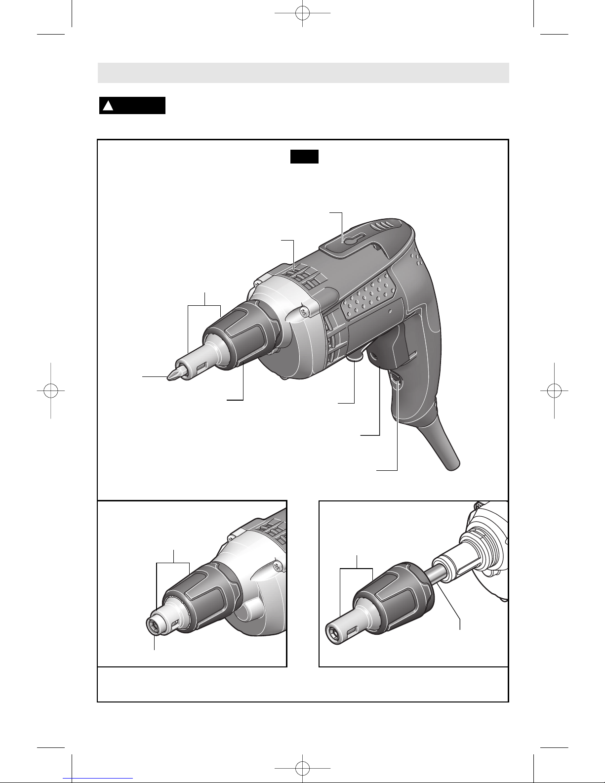
Functional Description and Specifications
Disconnect the plug from the power source before making any
assembly, adjustments or changing accessories
. Such preventive safety
measures reduce the risk of starting the tool accidentally.
!
WARNING
DEPTH ADJUSTING
SLEEVE
“LOCK-ON” BUTTON
REVERSING
SWITCH LEVER
BELT CLIP
VENTILATION
OPENINGS
Drivers
BIT TIP
FIG. 1
Model SG25MT only
HEX HEAD
VARIABLE SPEED CONTROLLED
TRIGGER SWITCH
NOTE: For tool specifications refer to the nameplate on your tool.
NOSE
PIECE
BIT
HOLDER
NOSE
PIECE
NOSE
PIECE
BM 2609932591 03-07 3/23/07 9:14 AM Page 6
-
7-
Operating Instructions
V
ARIABLE SPEED CONTROLLED
TRIGGER SWITCH
Your tool is equipped with a variable speed trigger
switch. The tool can be turned "ON" or "OFF" by
squeezing or releasing the trigger. The speed
can be adjusted from the minimum to maximum
nameplate RPM by the pressure you apply to the
trigger. Apply more pressure to increase the
speed and release pressure to decrease speed.
"LOCK-ON" BUTTON
The "Lock-ON" button, located near the trigger
allows for continuous operation at maximum
RPM without holding the trigger.
TO LOCK TRIGGER "ON": squeeze trigger,
depress button and release trigger.
TO UNLOCK THE TRIGGER: squeeze trigger
and release it without depressing the "LockON" button.
If the “Lock-ON” button is
continuously being de-
pressed, the trigger can not be released.
R
EVERSING SWITCH LEVER
The reversing switch lever is located above the
trigger switch and is used to reverse rotation of
the bit.
To use driver in "Forward" rotation, move lever
to left side of tool. To "Reverse" the rotation of
the bit move the lever to the right side of the
tool. The center position of the lever is the
"Lock-OFF" position.
Do not change direction of
rotation until the tool comes to
a complete stop. Shifting during rotation of the
chuck can cause damage to the tool.
BELT CLIP
Your tool is equipped with a belt clip that allows
you to conveniently attach your driver to your
belt. This feature will allow you to have both
hands free when climbing a ladder or moving to
another work area.
!
WARNING
1. Support the tool so that steady, even
pressure is applied to the screwdriving bit.
Operate the trigger switch by depressing with
one or two fingers.
2. Lock the tool on for continuous operation.
The bit will not rotate until the clutch is
engaged.
3. Place a drywall screw on the bit. The
magnetic bit holder will hold any steel drywall
screw without any additional assistance.
4. Press the screw point against the drywall
with steady even pressure. At this point, the
clutch will engage, driving the screw to the preset depth. Once the screw bottoms out, a
ratcheting sound will be heard for a second.
5. When properly set, the screw head should
pull into the drywall paper without cracking or
tearing the paper, then release slightly below
flush with the drywall board. In this manner,
minimum work is left when spackling screw
heads and taping the seams.
6. If it becomes necessary to remove a screw,
either adjust the nose piece to expose the bit
tip or remove the nose piece to expose the bit
tip , reverse the direction of rotation (when the
motor is in the "OFF" position.) Place the bit tip
into the screw, switch tool "ON" and apply
pressure to engage the clutch and remove
screw. When finished, press the nose piece
back into place or re-adjust the depth. Set
lever back to forward while the trigger switch is
in the “OFF” position.
!
CAUTION
Tool Tips
DEPTH CONTROL
The depth control should be adjusted so that
the drywall screw is set slightly below the
drywall surface.
DEPTH ADJUSTMENT
Your driver will continue to drive as long as
enough pressure is applied to the bit to keep
the clutch engaged. The nose piece, upon
contacting the work, prevents further pressure
BM 2609932591 03-07 3/23/07 9:14 AM Page 7
-8-
on the bit. Driving then stops regardless of
pressure continued by the operator.
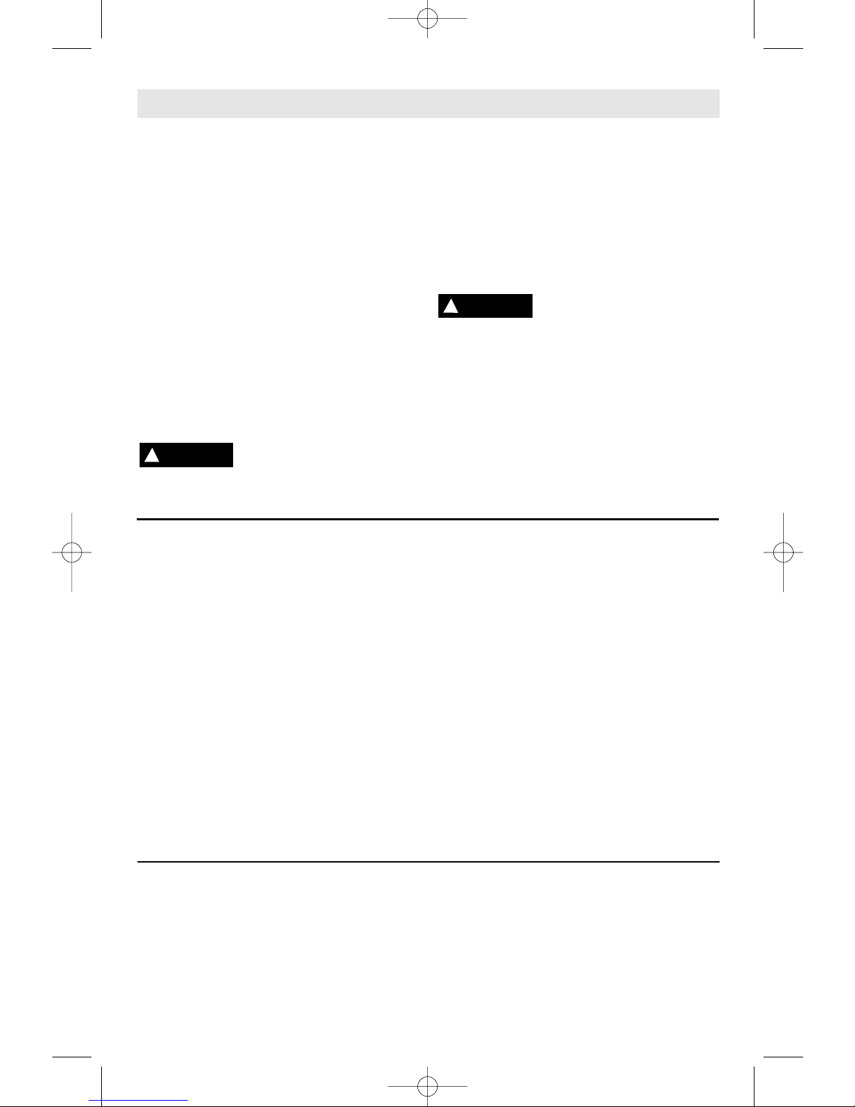
1. Rotate the depth adjusting sleeve until the
nose piece reaches the desired position.
2. Each click of the depth adjusting sleeve
e
quals a 0.25mm change in depth. One full
3
60 degree turn equals 2mm (Fig. 2).
3. Before beginning, always test-drive a sample
screw into a piece of scrap installation material
to check desired depth setting.
DEPTH
A
DJUSTING
SLEEVE
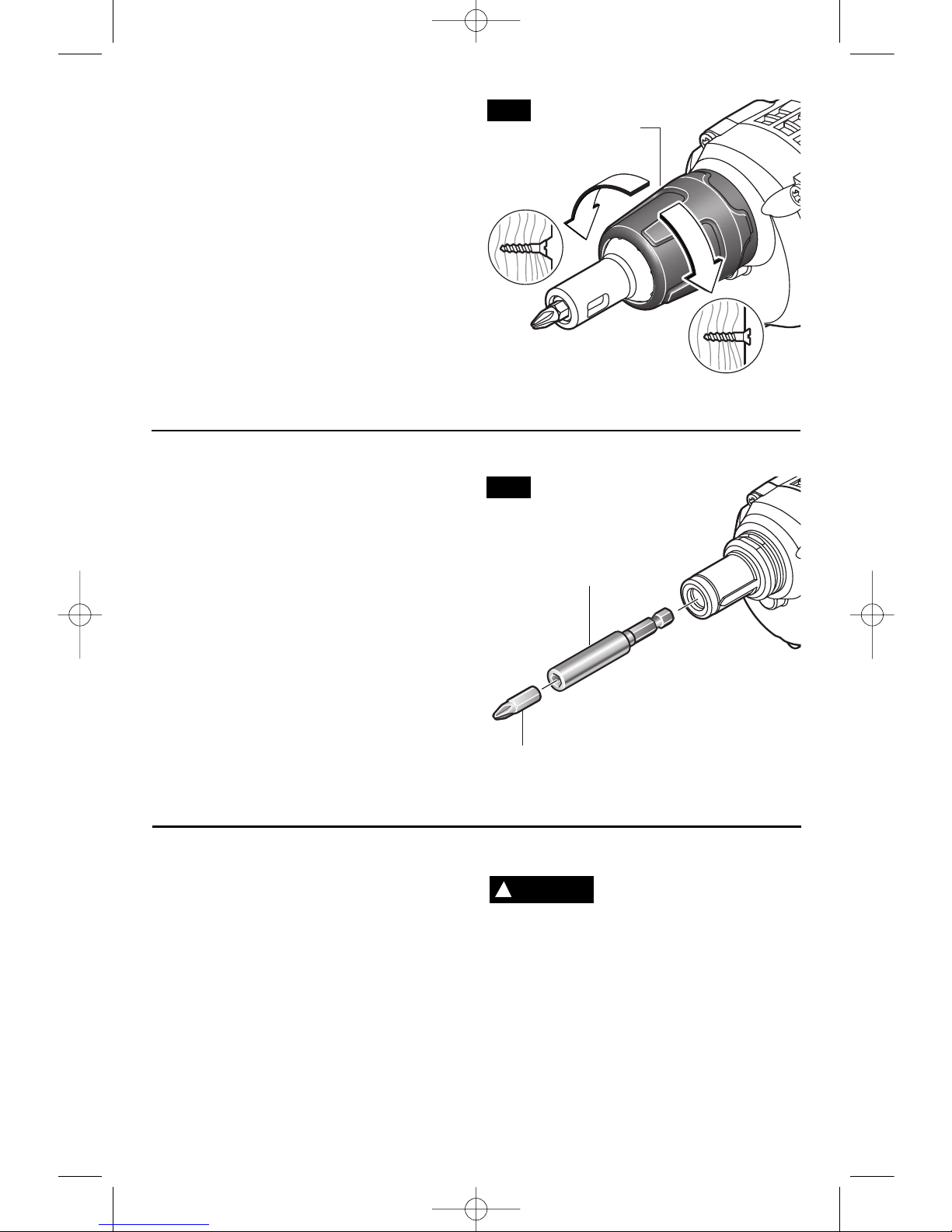
REPLACING BIT TIPS AND
BIT TIP HOLDERS
1. Remove the nose piece by grasping firmly
WITH FINGERS and pulling straight out. DO
NOT USE PLIERS.
2. Remove the bit tip by grasping firmly and
pulling straight out. If the bit tip holder comes
out with the bit, separate them. If you are
replacing the bit tip holder too, grasp it firmly
and pull it straight out. If you cannot remove the
bit tip or the bit tip holder using fingers only, you
may use pliers on these two parts only (Fig. 3).
DO NOT USE PLIERS ON NOSE PIECE.
Reverse the process to the point of installing
nose piece. Then WITH YOUR FINGERS,
install nose piece by pushing inward.
BIT TIP
BIT
HOLDER
CAPACITIES
Model
Nominal Capacity
SG45 All available sharp point drywall
SG45M
screws in 20 - 25 gauge studs.
SG45M-50 All available drill point drywall
SG45M-50G screws in 20 - 25 gauge studs.
SG25M All available sharp point screws in
20 - 25 gauge studs. All available
drill point drywall screws in 14 - 20
gauge studs.
SG25MT 1/4", 5/16" & 3/8" hex head
screws.
The use of any accessory or
attachment other than those
recommended in this instruction manual or the
BOSCH Catalog for this tool - may create a
hazard.
!
WARNING
FIG. 2
FIG. 3
BM 2609932591 03-07 3/23/07 9:14 AM Page 8

-9-
Service
Preventive maintenance
performed by unauthorized personnel may result in misplacing
of internal wires and components which
could cause serious hazard.
We
recommend that all tool service be performed
by a Bosch Factory Service Center or Authorized Bosch Service Station.
TOOL LUBRICATION
Your Bosch tool has been properly lubricated
and is ready to use. It is recommended that
tools with gears be regreased with a special
gear lubricant at every brush change.
CARBON BRUSHES
The brushes and commutator in your tool
have been engineered for many hours of
dependable service. To maintain peak
efficiency of the motor, we recommend every
two to six months the brushes be examined.
Only genuine Bosch replacement brushes
specially designed for your tool should be
used.
BEARINGS
After about 300-400 hours of operation, or at
every second brush change, the bearings
should be replaced at Bosch Factory Service
Center or Authorized Bosch Service Station.
Bearings which become noisy (due to heavy
load or very abrasive material cutting) should
be replaced at once to avoid overheating or
motor failure.
Cleaning
To avoid accidents always
disconnect the tool from
the power supply before cleaning or
performing any maintenance.
The tool may
be cleaned most effectively with compressed
dry air.
Always wear safety goggles when
cleaning tools with compressed air.
Ventilation openings and switch levers must
be kept clean and free of foreign matter. Do
not attempt to clean by inserting pointed
objects through openings.
Certain cleaning agents
and solvents damage
plastic parts.
Some of these are: gasoline,
carbon tetrachloride, chlorinated cleaning
solvents, ammonia and household
detergents that contain ammonia.
!
WARNING
!
WARNING
Maintenance
!
CAUTION
Accessories
If an extension cord is
necessary, a cord with
adequate size conductors that is capable
of carrying the current necessary for your
tool must be used.
This will prevent
excessive voltage drop, loss of power or
overheating. Grounded tools must use 3-wire
extension cords that have 3-prong plugs and
receptacles
.
NOTE: The smaller the gauge number, the
heavier the cord.
RECOMMENDED SIZES OF EXTENSION CORDS
120 VOLT ALTERNATING CURRENT TOOLS
!
WARNING
(Models SG45, SG45M, SG45M-50,
SG45M-50G & SG25M only)
1/4" Hex Universal Bit Holder and #2 phillips
bit standard equipment on drywall drivers.
(Model SG25MT only)
1/4" , 5/16" and 3/8" magnetic hex nut
setters.
Tool’s
Ampere
Rating
Cord Size in A.W.G.
Wire Sizes in mm
2
3-6
6-8
8-10
10-12
12-16
18
16
16 14
0.75 0.75 1.5 2.5
18 16
14 12 0.75 1.0 2.5 4.0
18
16
14
12 0.75 1.0 2.5 4.0
16
16
14 12 1.0 2.5 4.0 —
14
12
—— ————
25 50 100 150 15 30 60 120
Cord Length in Feet Cord Length in Meters
BM 2609932591 03-07 3/23/07 9:14 AM Page 9
 Loading...