

Bosch SEC-3402 Quick Installation Manual
FCC/IC Information
This device complies with Part 15 FCC Rules
and Industry Canada's license-exempt RSSs. Operation is subject to these conditions: (1) this
device may not cause harmful interference, and
(2) this device must accept any interference received including interference that may cause undesired operation.
Notice!
For the full FCC/IC information, refer to
the Security Escort Point Tracking Trans-
mitter Installation Manual, downloadable
from http://www.boschsecurity.com.
Installation and Setup
This section provides information for system
planners and configurators.
Mounting the point transmitter
Notice!
Avoid mounting the point transmitter
on metal surfaces as it can reduce the
range of the unit.
Recommended mounting
1. Position the mounting plate over the desired
location and attach it with the supplied
screws.
Fig.1: Attach mounting plate
1 Release tab 2 Mounting holes
2. Open the cover using a screwdriver.
Fig.2: Open cover
1 Insert screwdriver
and press here
2 Push in
3. Be sure to note the location of the magnet
when mounting the base.
4. Slide the point transmitter over the base to
lock it into place.
Fig.3: Slide point transmitter over base
5. The point transmitter can be released from
the base by pressing the release tab with a
small screwdriver or a paper clip.
6. For higher security installations, mount the
transmitter using the tamper screw
provided.
Fig.4: Mount transmitter using tamper
screw
1 Tamper screw
Mounting without the mounting plate
1. If the battery was installed in the point transmitter, remove it at this time.
2. Using a small screwdriver, gently lift the
printed circuit board away from the case
mounting clips. You do not need to remove
the cover to remove the board.
Fig.5: Lift printed circuit board
3. Rock the board gently to loosen the battery
clips from the case and slide the board away
from the mounting clips near the area where
the cover connects to the base.
4. Mount the point transmitter in the desired
location, taking note the magnet needs to be
on the same side of the case as the reed
switch.
Fig.6: Mount point transmitter in desired
position
1 Magnet side 2 Mounting holes
Mounting the magnet
Mount the magnet as shown in the following figure. The magnet must mount within 19 mm
(0.75 in.) of the base of the unit.
Fig.7: Mount the magnet
1 End view from the opening end
Powering up the point transmitter
The SEC-3402 series can be powered up either
by 3V battery or 12 VDC input, depending on the
setting of the jumper.
3V battery
1. Check that the jumper is set over the jumper
pins marked by the symbol. This is the
default factory setting on the point transmitter.
2. Install the recommended type of battery:
Duracell® DL123A, Energizer® EL123AP or
Panasonic® CR123A. Be sure to observe the
polarity.
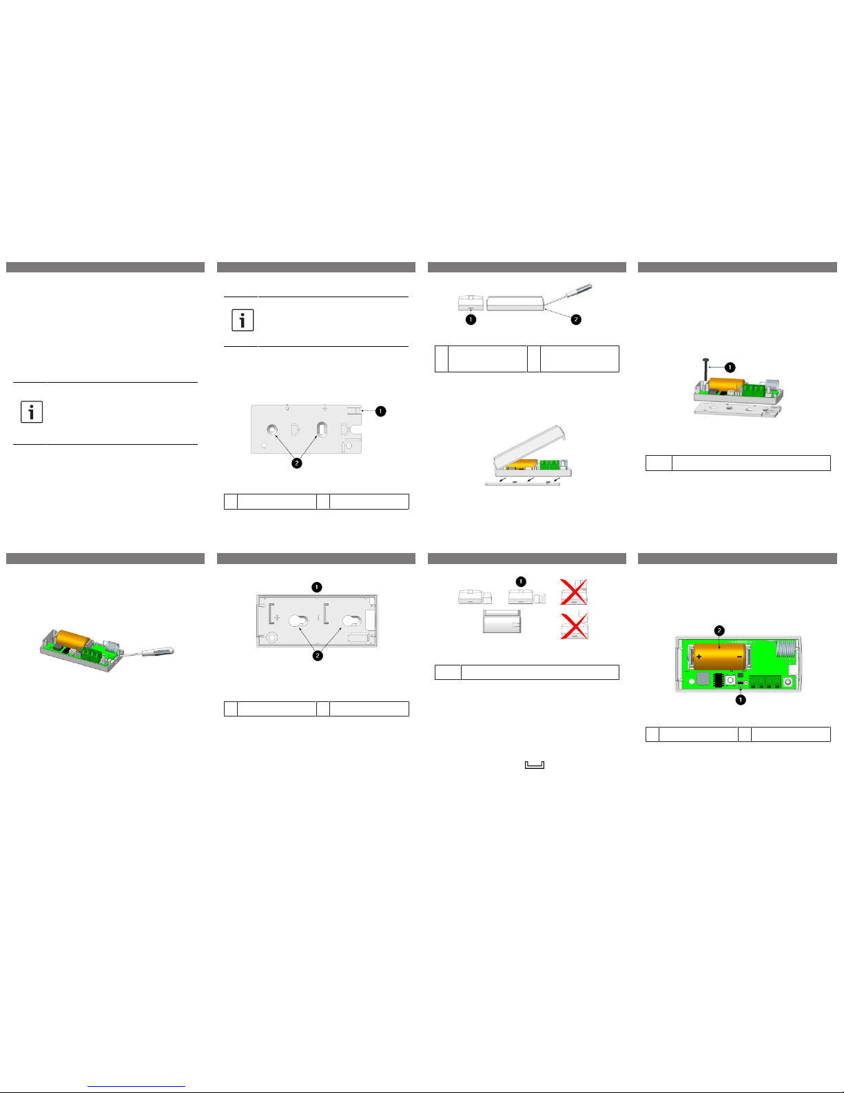
Fig.8: Install battery
1 Jumper setting 2 Battery
12 VDC input
1. Set the jumper over the jumper pins as illustrated in the diagram below.
2. Connect the 12 VDC source to the connector
of the transmitter.
1 | 2 | 3 | 4 |
5 | 6 | 7 | 8 |
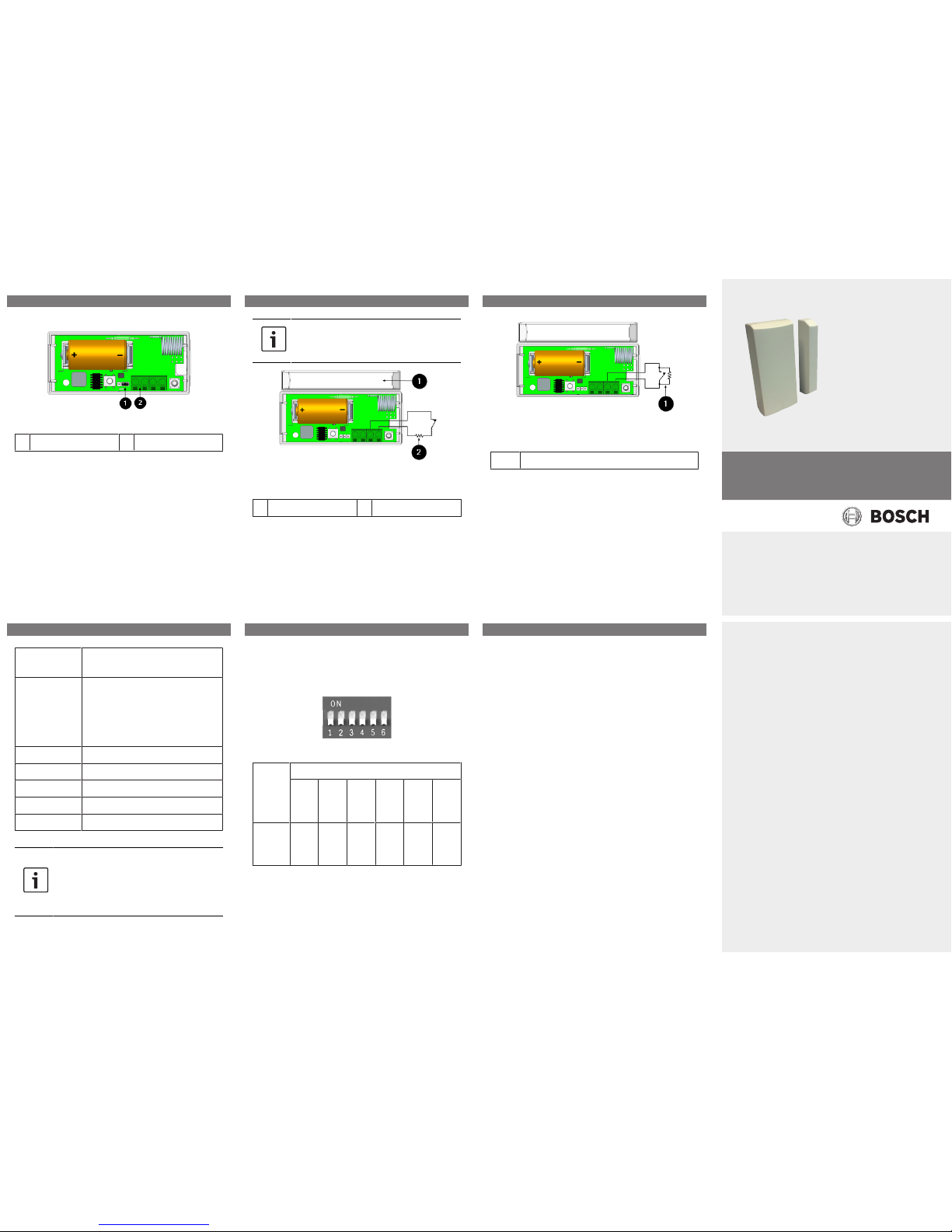
Fig.9: 12 VDC input
1 Jumper setting 2 12 VDC in
Setting up magnetic or external
contacts
The SEC-3402 series has the capacity to monitor
magnetic and/or dry external contacts. External
Normally Closed (NC) or external Normally Open
(NO) contacts can be monitored.
Recommended cable: 18 AWG < 20 ft (6 m)
EOL resistor: 1 Mega ohms
Notice!
If not using external contacts, you must
install the EOL resistor.
Fig.10: Magnet (optional) typical NC wiring
1 Magnet bar 2 EOL resistor
Fig.11: Magnet (optional) typical NO wiring
1 EOL resistor
Enabling and Disabling Features
The features of SEC-3402 series can be set, enabled or disabled accordingly using its dip
switch. There are 6 switches on the dip switch.
Usage of the dip switch is explained as of below:
Switch Num-
ber
Usage
1 Frequency Selection:
OFF - 304 MHz (default setting)
ON - 303.825 MHz
(Not applicable to
SEC-3402-433)
2 Auto-track (every 7 seconds)
3 Displacement Detection
4 Reed Switch
5 Buzzer
6 Not Used
Notice!
Remove the battery before setting the
dip switches. Changes to the dip
switches should be performed by administrators only.
Default dip switch setting
The default setting of the SEC-3402 series dip
switch is as follows:
Default
Setting
Switch Number on Dip Switch
1 2 3 4 5 6
(not
used)
Switch
Position
OFF OFF OFF OFF OFF OFF
9 | 10 | 11 |
12 | 13 | 14 |
Security Escort Point Tracking Transmitters
SEC-3402 Series
en Quick Installation Guide
Robert Bosch (SEA) Pte Ltd
11 Bishan Street 21
573943 Singapore
Singapore
www.boschsecurity.com
© Robert Bosch (SEA) Pte Ltd, 2018
Bosch Sicherheitssysteme GmbH
Robert-Bosch-Ring 5
85630 Grasbrunn
Germany
© Bosch Sicherheitssysteme GmbH, 2018
F.01U.347.391 | SE3v1.1
 Loading...