

Bosch Rexroth IndraControl VCP 05.2 Project Planning Manual
Electric Drives
and Controls Pneumatics
Service
Linear Motion and
Assembly Technologies
Hydraulics
II Bosch Rexroth AG | Electric Drives and Controls Rexroth IndraControl VCP 05 | R911310377 / 02
Title Rexroth IndraControl VCP 05.2
Type of Documentation Project Planning Manual
Document Typecode DOK-SUPPL*-VCP*05.2***-PR02-EN-P
Internal File Reference Document Number, 120-2100-B375-02/EN
Pupose of Documentation This document serves to describe the different variants of the
VCP 05.
Record of Revisions
Description Release
Notes
Date
120-2100-B375-01/EN 05.2005 First Edition
120-2100-B375-02/EN 05.2006 Second Edition
Copyright
© Bosch Rexroth AG, 2006
Copying this document, giving it to others and the use or
communication of the contents thereof without express authority,
are forbidden. Offenders are liable for the payment of damages.
All rights are reserved in the event of the grant of a patent or the
registration of a utility model or design (DIN 34-1).
Validity The specified data is for product description purposes only and
may not be deemed to be guaranteed unless expressly
confirmed in the contract. All rights are reserved with respect to
the content of this documentation and the availability of the
product.
Published by Bosch Rexroth AG
Bgm.-Dr.-Nebel-Str. 2
D-97816 Lohr a. Main
Tel.: +49 (0) 93 52 / 40-0
Fax: +49 (0) 93 52 /40-45 85
http://www.boschrexroth.com/
Abt.: BRC/EPY (NH)
Note This document has been printed on chlorine-free bleached
paper.

R911310377 / 02 | Rexroth IndraControl VCP 05 Electric Drives and Controls | Bosch Rexroth AG III
Table of Contents
Table of Contents
1 Introducing the System .............................. 1–1
1.1 Brief Description of the VCP 05....................................... 1–1
1.2 Operating System............................................................ 1–2
1.3 Commissioning ................................................................ 1–2
2 Important Directions for Use...................... 2–1
2.1 Appropriate Use............................................................... 2–1
2.1.1 Introduction ................................................................... 2–1
2.1.2 Areas of Use and Application ....................................... 2–2
2.2 Inappropriate Use ............................................................ 2–2
3 Safety Instructions for Electric Drives and
Controls ....................................................... 3–1
3.1 Introduction...................................................................... 3–1
3.2 Explanations .................................................................... 3–1
3.3 Hazards by Improper Use................................................ 3–2
3.4 General Information......................................................... 3–2
3.5 Protection Against Contact with Electrical Parts.............. 3–4
3.6 Protection Against Electric Shock by Protective Low
Voltage (PELV)................................................................ 3–5
3.7 Protection Against Dangerous Movements ..................... 3–6
3.8 Protection Against Magnetic and Electromagnetic Fields
During Operation and Mounting ...................................... 3–7
3.9 Protection Against Contact with Hot Parts....................... 3–8
3.10 Protection During Handling and Mounting....................... 3–9
3.11 Battery Safety .................................................................. 3–9
3.12 Protection Against Pressurized Systems....................... 3–10
4 Technical Data............................................. 4–1
4.1 Front Panel and Enclosure .............................................. 4–1
4.2 Keyboard ......................................................................... 4–1
4.3 Display............................................................................. 4–2
4.4 Electrical Data ................................................................. 4–2
4.5 Interfaces......................................................................... 4–3
4.6 Central Processing Unit and Memory.............................. 4–4
4.7 Connection System ......................................................... 4–4
4.8 Environmental Conditions................................................ 4–5
4.9 Applied Standards and Guidelines .................................. 4–6
4.10 Compatibility Test ............................................................ 4–7
5 Dimensions.................................................. 5–1
5.1 Installation ....................................................................... 5–1
5.1.1 Front Panel Dimensions ............................................... 5–2

IV Bosch Rexroth AG | Electric Drives and Controls Rexroth IndraControl VCP 05 | R911310377 / 02
Table of Contents
5.1.2 Mounting Cutout ........................................................... 5–3
5.1.3 Side View with Dimensions .......................................... 5–4
6 Display and Operating Components......... 6–1
6.1 Display............................................................................. 6–1
6.1.1 Setting the Contrast...................................................... 6–1
6.1.2 Character Attributes...................................................... 6–2
6.1.3 Fonts............................................................................. 6–2
6.2 Keyboard ......................................................................... 6–2
6.2.1 Editing Keys.................................................................. 6–2
6.2.2 Navigation Keys............................................................ 6–4
6.2.3 Special Keys ................................................................. 6–4
6.2.4 Function Keys ............................................................... 6–6
6.2.4.1 Slide-in Identification Strips for the Function Keys .... 6–6
7 Interfaces ..................................................... 7–1
7.1 Standard Interfaces ......................................................... 7–2
7.1.1 Ethernet (X5) ................................................................ 7–2
7.1.1.1 Pin Assignment.......................................................... 7–2
7.1.1.2 Cable ......................................................................... 7–2
7.1.1.3 Diagnostics ................................................................ 7–3
7.1.2 USB (X9, X10) .............................................................. 7–3
7.1.2.1 Cable ......................................................................... 7–3
7.2 Serial Interfaces .............................................................. 7–4
7.2.1 RS485 (X6-SER1) ........................................................ 7–5
7.2.1.1 Pin Assignment.......................................................... 7–5
7.2.1.2 Termination................................................................ 7–6
7.2.2 RS232 (X6-SER1) ........................................................ 7–7
7.2.2.1 Pin Assignment.......................................................... 7–7
7.2.2.2 Termination................................................................ 7–7
7.2.3 RS232 (X6-SER2) ........................................................ 7–8
7.2.3.1 Pin Assignment.......................................................... 7–8
7.3 Field Bus Interfaces......................................................... 7–9
7.3.1 DeviceNet Slave (X6) ................................................... 7–9
7.3.1.1 Pin Assignment........................................................ 7–10
7.3.1.2 Cable ....................................................................... 7–10
7.3.1.3 Termination.............................................................. 7–11
7.3.1.4 Diagnostics .............................................................. 7–11
7.3.2 PROFIBUS DP Slave (X6) ......................................... 7–12
7.3.2.1 Pin Assignment........................................................ 7–13
7.3.2.2 Cable ....................................................................... 7–14
7.3.2.3 Termination.............................................................. 7–14
7.3.2.4 Diagnostics .............................................................. 7–14
7.4 Shielding D-SUB Connectors ........................................ 7–15
8 Maintenance and Installation..................... 8–1
8.1 General Information......................................................... 8–1
8.2 Exchange of Hardware Components .............................. 8–1
8.3 Data Backup.................................................................... 8–1
8.4 Unpacking the Device ..................................................... 8–1

R911310377 / 02 | Rexroth IndraControl VCP 05 Electric Drives and Controls | Bosch Rexroth AG V
Table of Contents
8.5 Identification .................................................................... 8–2
8.6 Connecting the Device .................................................... 8–3
8.6.1 Supply Voltage 24 V ..................................................... 8–3
8.7 Front Panel ...................................................................... 8–4
8.8 Fuse................................................................................. 8–5
8.9 Battery ............................................................................. 8–5
8.9.1 Changing the Battery .................................................... 8–5
8.9.2 Battery Disposal............................................................ 8–6
9 Ordering Information .................................. 9–1
9.1 Type Code ....................................................................... 9–1
9.2 Accessories ..................................................................... 9–2
9.2.1 Ethernet Cable .............................................................. 9–3
10 Disposal and Environmental Protection . 10–1
10.1 Disposal .........................................................................10–1
10.1.1 Products...................................................................... 10–1
10.1.2 Packaging Materials ................................................... 10–1
10.2 Environmental Protection .............................................. 10–1
10.2.1 No Release of Hazardous Substances....................... 10–1
10.2.2 Materials Contained in the Products........................... 10–1
10.2.2.1 Electronic Devices.................................................... 10–1
10.2.2.2 Motors ...................................................................... 10–2
10.2.3 Recycling .................................................................... 10–2
11 Table of Figures ........................................ 11–1
12 Index........................................................... 12–1
13 Service & Support ..................................... 13–1
13.1 Helpdesk........................................................................ 13–1
13.2 Service-Hotline .............................................................. 13–1
13.3 Internet .......................................................................... 13–1
13.4 Vor der Kontaktaufnahme... - Before contacting us....... 13–2
13.5 Kundenbetreuungsstellen - Sales & Service Facilities .. 13–2
13.5.1 Deutschland - Germany .............................................. 13–2
13.5.2 Europa (West) - Europe (West) .................................. 13–3
13.5.3 Europa (Ost) - Europe (East) ...................................... 13–4
13.5.4 Afrika, Asien, Australien (inkl. Pazifischer Raum) -
Africa, Asia, Australia (incl. Pacific Rim)..................... 13–5
13.5.5 Nordamerika - North America ..................................... 13–6
13.5.6 Südamerika - South America ...................................... 13–6

VI Bosch Rexroth AG | Electric Drives and Controls Rexroth IndraControl VCP 05 | R911310377 / 02
Table of Contents
R911310377 / 02 | Rexroth IndraControl VCP 05 Electric Drives and Controls | Bosch Rexroth AG 1-1
Introducing the System
1 Introducing the System
1.1 Brief Description of the VCP 05
The small operator terminal is a machine operating terminal which can
initiate functions in the machine as defined in the application.
Its compact design and seal running around the rear of the device
make it particularly suitable for a large variety of applications. Furthermore, every mounting position is possible.
Depending on the variant, the small operator terminal is equipped
either with two serial interfaces or with a fieldbus interface.
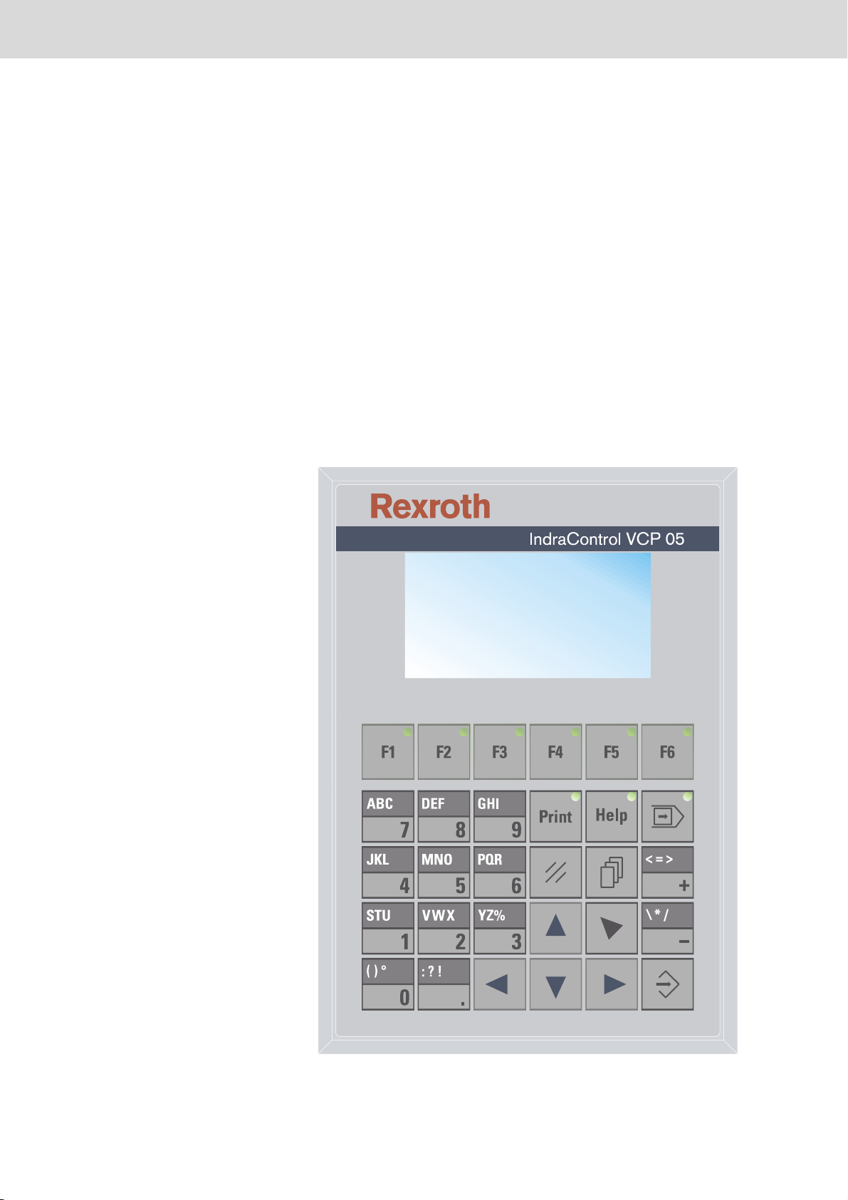
The front panel with a membrane keypad is made up of a 5 mm thick
aluminum plate with chamfered edges which are provided with a chemically resistant polyester foil with embossing.
Fig. 1-1: VCP 05 with keypad

1-2 Bosch Rexroth AG | Electric Drives and Controls Rexroth IndraControl VCP 05 | R911310377 / 02
Introducing the System
1.2 Operating System
The Windows CE operating system is installed on the small operator
terminal.
1.3 Commissioning
Mount the device properly (for more information, see chapter Dimensions). Then connect the device to the voltage supply and to the control
unit or the field bus system, if required.
R911310377 / 02 | Rexroth IndraControl VCP 05 Electric Drives and Controls | Bosch Rexroth AG 2-1
Important Directions for Use
2 Important Directions for Use
2.1 Appropriate Use
2.1.1 Introduction
Rexroth products represent state-of-the-art developments and manufacturing. They are tested prior to delivery to ensure operating safety
and reliability.
The products may only be used in the manner that is defined as appropriate. If they are used in an inappropriate manner, then situations can
develop that may lead to property damage or injury to personnel.
Bosch Rexroth, as manufacturer, is not liable for any damages resulting
from inappropriate use. In such cases, the guarantee and the right to
payment of damages resulting from inappropriate use are forfeited. The
user alone carries all responsibility of the risks.
Before using Rexroth products, make sure that all the pre-requisites for
appropriate use of the products are satisfied:
• Personnel that in any way, shape or form uses our products must first
read and understand the relevant safety instructions and be familiar
with appropriate use.
• If the product takes the form of hardware, then they must remain in
their original state, in other words, no structural changes are permitted. It is not permitted to decompile software products or alter source
codes.
• Do not mount damaged or faulty products or use them in operation.
• Make sure that the products have been installed in the manner de-
scribed in the relevant documentation.

2-2 Bosch Rexroth AG | Electric Drives and Controls Rexroth IndraControl VCP 05 | R911310377 / 02
Important Directions for Use
2.1.2 Areas of Use and Application
The small operator terminal VCP 05 made by Bosch Rexroth allows to
operate and control machines and installations and serves to visualize
the information on the machine/installation to be operated required by
the user.
The VCP 05 may only be used with the accessories and parts specified
in this document. If a component has not been specifically named, then
it may not be either mounted or connected. The same applies to cables
and lines.Operation is only permitted in the specified configurations and
combinations of components using the software and firmware as specified in the relevant function descriptions.
The small operator terminals VCP 05 have been developed for use in
single or multiple-axis control tasks.
Typical applications of the VCP 05 are:
• Handling and assembly systems,
• Packaging machines,
• Printing and paper processing machines and
• Machine tools.
The VCP 05 may only be operated under the assembly, installation and
ambient conditions as described here (temperature, system of protection, humidity, EMC requirements, etc.) and in the position specified.
2.2 Inappropriate Use
Using the small operator terminal outside of the above-referenced
areas of application or under operating conditions other than described
in the document and the technical data specified is defined as “inappropriate use".
The small operator terminal may not be used, if
• they are subject to operating conditions that do not meet the above
• Bosch Rexroth has not specifically released them for that intended
specified ambient conditions. This includes, for example, operation
under water, in the case of extreme temperature fluctuations or extremely high maximum temperatures or if
purpose. Please note the specifications outlined in the general Safety Guidelines!
R911310377 / 02 | Rexroth IndraControl VCP 05 Electric Drives and Controls | Bosch Rexroth AG 3-1
Safety Instructions for Electric Drives and Controls
3 Safety Instructions for Electric Drives and Controls
3.1 Introduction
Read these instructions before the initial startup of the equipment in
order to eliminate the risk of bodily harm or material damage. Follow
these safety instructions at all times.Do not attempt to install or start up
this equipment without first reading all documentation provided with the
product. Read and understand these safety instructions and all user
documentation of the equipment prior to working with the equipment at
any time. If you do not have the user documentation for your equipment, contact your local Bosch Rexroth representative to send this
documentation immediately to the person or persons responsible for
the safe operation of this equipment. If the equipment is resold, rented
or transferred or passed on to others, then these safety instructions
must be delivered with the equipment.
3.2 Explanations
WARNING
Improper use of this equipment, failure to follow the safety instructions in this document or tampering with the product, including
disabling of safety devices, may result in material damage, bodily
harm, electric shock or even death!
The safety instructions describe the following degrees of hazard seriousness in compliance with ANSI Z535. The degree of hazard seriousness informs about the consequences resulting from non-compliance
with the safety instructions.
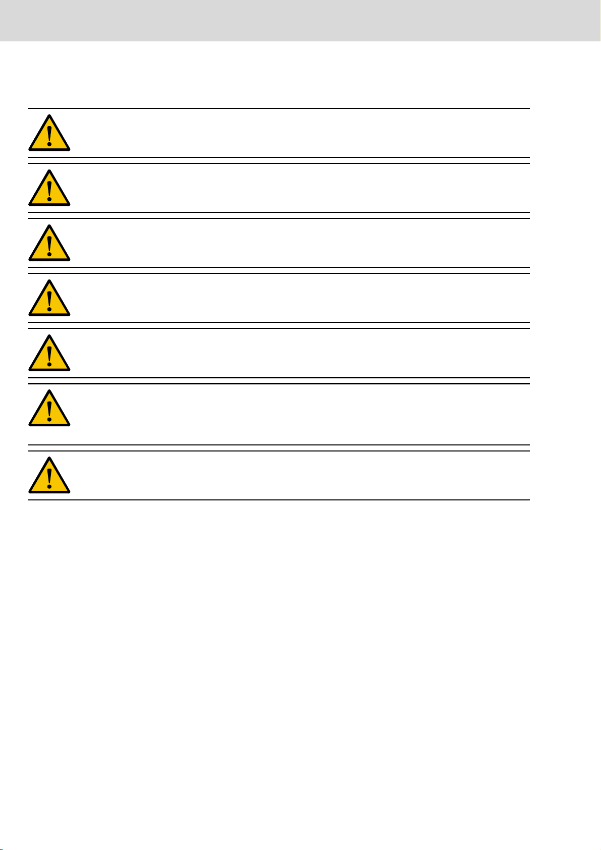
Warning
symbol
Signal word and degree of hazard seriousness
according to ANSI
DANGER
Death or severe bodily harm will occur.
WARNING
Death or severe bodily harm may occur.
CAUTION
Bodily harm or material damage may occur.
Fig. 3-1: Hazard classification (according to ANSI Z535)
3-2 Bosch Rexroth AG | Electric Drives and Controls Rexroth IndraControl VCP 05 | R911310377 / 02
Safety Instructions for Electric Drives and Controls
3.3 Hazards by Improper Use
DANGER
High voltage and high discharge current! Danger to life or severe bodily
harm by electric shock!
DANGER
Dangerous movements! Danger to life, severe bodily harm or material
damage by unintentional motor movements!
WARNING
High electrical voltage due to wrong connections! Danger to life or bodily
harm by electric shock!
WARNING
Health hazard for persons with heart pacemakers, metal implants and
hearing aids in proximity to electrical equipment!
CAUTION
Surface of machine housing could be extremely hot! Danger of injury!
Danger of burns!
CAUTION
Risk of injury due to improper handling! Bodily harm caused by crushing, shearing, cutting and mechanical shock or incorrect handling of
pressurized systems!
CAUTION
Risk of injury due to incorrect handling of batteries!
3.4 General Information
• Bosch Rexroth AG is not liable for damages resulting from failure to
observe the warnings provided in this documentation.
• Read the operating, maintenance and safety instructions in your language before starting up the machine. If you find that you cannot
completely understand the documentation for your product, please
ask your supplier to clarify.
• Proper and correct transport, storage, assembly and installation as
well as care in operation and maintenance are prerequisites for optimal and safe operation of this equipment.
• Only persons who are trained and qualified for the use and operation
of the equipment may work on this equipment or within its proximity.

R911310377 / 02 | Rexroth IndraControl VCP 05 Electric Drives and Controls | Bosch Rexroth AG 3-3
Safety Instructions for Electric Drives and Controls
• Furthermore, they must be trained, instructed and qualified to switch
electrical circuits and equipment on and off in accordance with technical safety regulations, to ground them and to mark them according
to the requirements of safe work practices. They must have adequate safety equipment and be trained in first aid.
• Only use spare parts and accessories approved by the manufacturer.
• Follow all safety regulations and requirements for the specific application as practiced in the country of use.
• The equipment is designed for installation in industrial machinery.
• The ambient conditions given in the product documentation must be
observed.
• Use only safety features and applications that are clearly and explicitly approved in the Project Planning Manual.
• For example, the following areas of use are not permitted: construction cranes, elevators used for people or freight, devices and vehicles to transport people, medical applications, refinery plants,
transport of hazardous goods, nuclear applications, applications
sensitive to high frequency, mining, food processing, control of protection equipment (also in a machine).
• The information given in the documentation of the product with regard to the use of the delivered components contains only examples
of applications and suggestions.
The machine and installation manufacturer must
• make sure that the delivered components are suited for his individual
application and check the information given in this documentation
with regard to the use of the components,
• make sure that his application complies with the applicable safety
regulations and standards and carry out the required measures,
modifications and complements.
• Startup of the delivered components is only permitted once it is sure
that the machine or installation in which they are installed complies
with the national regulations, safety specifications and standards of
the application.
• Operation is only permitted if the national EMC regulations for the application are met.
• The instructions for installation in accordance with EMC requirements can be found in the documentation "EMC in Drive and Control
Systems".
• Technical data, connections and operational conditions are specified
in the product documentation and must be followed at all times.
The machine or installation manufacturer is responsible for compliance
with the limiting values as prescribed in the national regulations.
• Technical data, connections and operational conditions are specified
in the product documentation and must be followed at all times.
3-4 Bosch Rexroth AG | Electric Drives and Controls Rexroth IndraControl VCP 05 | R911310377 / 02
Safety Instructions for Electric Drives and Controls
3.5 Protection Against Contact with Electrical Parts
This section refers to equipment and drive components with voltages
above 50 Volts.
Touching live parts with voltages of 50 Volts and more with bare hands
or conductive tools or touching ungrounded housings can be dangerous and cause electric shock. In order to operate electrical equipment,
certain parts must unavoidably have dangerous voltages applied to
them.
DANGER
High electrical voltage! Danger to life, severe bodily harm by electric shock!
• Only those trained and qualified to work with or on electrical equipment are permitted to operate, maintain or repair this equipment.
• Follow general construction and safety regulations when working on
high voltage installations.
• Before switching on power the ground wire must be permanently
connected to all electrical units according to the connection diagram.
• Do not operate electrical equipment at any time, even for brief measurements or tests, if the ground wire is not permanently connected
to the points of the components provided for this purpose.
• Before working with electrical parts with voltage higher than 50 V, the
equipment must be disconnected from the mains voltage or power
supply. Make sure the equipment cannot be switched on again unintended.
• The following should be observed with electrical drive and filter components:
Wait five (5) minutes after switching off power to allow capacitors to discharge before beginning to work. Measure the voltage on the capacitors
before beginning to work to make sure that the equipment is safe to
touch.
• Never touch the electrical connection points of a component while
power is turned on.
• Install the covers and guards provided with the equipment properly
before switching the equipment on. Prevent contact with live parts at
any time.
• A residual-current-operated protective device (RCD) must not be
used on electric drives! Indirect contact must be prevented by other
means, for example, by an overcurrent protective device.
• Electrical components with exposed live parts and uncovered high
voltage terminals must be installed in a protective housing, for example, in a control cabinet.
R911310377 / 02 | Rexroth IndraControl VCP 05 Electric Drives and Controls | Bosch Rexroth AG 3-5
Safety Instructions for Electric Drives and Controls
To be observed with electrical drive and filter components:
DANGER
High electrical voltage on the housing! High leakage current! Danger to life, danger of injury by electric shock!
• Connect the electrical equipment, the housings of all electrical units
and motors permanently with the safety conductor at the ground
points before power is switched on. Look at the connection diagram.
This is even necessary for brief tests.
• Connect the safety conductor of the electrical equipment always permanently and firmly to the supply mains. Leakage current exceeds
3.5 mA in normal operation.
• Use a copper conductor with at least 10 mm
2
cross section over its
entire course for this safety conductor connection!
• Prior to startups, even for brief tests, always connect the protective
conductor or connect with ground wire. Otherwise, high voltages can
occur on the housing that lead to electric shock.
3.6 Protection Against Electric Shock by Protective Low Voltage (PELV)
All connections and terminals with voltages between 0 and 50 Volts on
Rexroth products are protective low voltages designed in accordance
with international standards on electrical safety.
WARNING
High electrical voltage due to wrong connections! Danger to life,
bodily harm by electric shock!
• Only connect equipment, electrical components and cables of the
protective low voltage type (PELV = Protective Extra Low Voltage)
to all terminals and clamps with voltages of 0 to 50 Volts.
• Only electrical circuits may be connected which are safely isolated
against high voltage circuits. Safe isolation is achieved, for example,
with an isolating transformer, an opto-electronic coupler or when
battery-operated.
3-6 Bosch Rexroth AG | Electric Drives and Controls Rexroth IndraControl VCP 05 | R911310377 / 02
Safety Instructions for Electric Drives and Controls
3.7 Protection Against Dangerous Movements
Dangerous movements can be caused by faulty control of the connected motors. Some common examples are:
• improper or wrong wiring of cable connections
• incorrect operation of the equipment components
• wrong input of parameters before operation
• malfunction of sensors, encoders and monitoring devices
• defective components
• software or firmware errors
Dangerous movements can occur immediately after equipment is
switched on or even after an unspecified time of trouble-free operation.
The monitoring in the drive components will normally be sufficient to
avoid faulty operation in the connected drives. Regarding personal
safety, especially the danger of bodily injury and material damage, this
alone cannot be relied upon to ensure complete safety. Until the integrated monitoring functions become effective, it must be assumed in
any case that faulty drive movements will occur. The extent of faulty
drive movements depends upon the type of control and the state of
operation.
DANGER
Dangerous movements! Danger to life, risk of injury, severe bodily
harm or material damage!
• Ensure personal safety by means of qualified and tested higher-level
monitoring devices or measures integrated in the installation. Unintended machine motion is possible if monitoring devices are disabled, bypassed or not activated.
Pay attention to unintended machine motion or other malfunction
in any mode of operation.
• Keep free and clear of the machine’s range of motion and moving
parts. Possible measures to prevent people from accidentally entering the machine’s range of motion:
– use safety fences
– use safety guards
– use protective coverings
– install light curtains or light barriers

R911310377 / 02 | Rexroth IndraControl VCP 05 Electric Drives and Controls | Bosch Rexroth AG 3-7
Safety Instructions for Electric Drives and Controls
• Fences and coverings must be strong enough to resist maximum
possible momentum, especially if there is a possibility of loose parts
flying off.
• Mount the emergency stop switch in the immediate reach of the operator. Verify that the emergency stop works before startup. Don’t
operate the machine if the emergency stop is not working.
• Isolate the drive power connection by means of an emergency stop
circuit or use a starting lockout to prevent unintentional start.
• Make sure that the drives are brought to a safe standstill before accessing or entering the danger zone. Safe standstill can be achieved
by switching off the power supply contactor or by safe mechanical
locking of moving parts.
• Secure vertical axes against falling or dropping after switching off the
motor power by, for example:
– mechanically securing the vertical axes
– adding an external braking/ arrester/ clamping mechanism
– ensuring sufficient equilibration of the vertical axes
The standard equipment motor brake or an external brake controlled di-
rectly by the drive controller are not sufficient to guarantee personal
safety!
• Disconnect electrical power to the equipment using a master switch
and secure the switch against reconnection for:
– maintenance and repair work
– cleaning of equipment
– long periods of discontinued equipment use
• Prevent the operation of high-frequency, remote control and radio
equipment near electronics circuits and supply leads. If the use of
such equipment cannot be avoided, verify the system and the installation for possible malfunctions in all possible positions of normal
use before initial startup. If necessary, perform a special electromagnetic compatibility (EMC) test on the installation.
3.8 Protection Against Magnetic and Electromagnetic Fields During Operation and Mounting
Magnetic and electromagnetic fields generated near current-carrying
conductors and permanent magnets in motors represent a serious
health hazard to persons with heart pacemakers, metal implants and
hearing aids.
WARNING
Health hazard for persons with heart pacemakers, metal implants and
hearing aids in proximity to electrical equipment!
3-8 Bosch Rexroth AG | Electric Drives and Controls Rexroth IndraControl VCP 05 | R911310377 / 02
Safety Instructions for Electric Drives and Controls
• Persons with heart pacemakers, hearing aids and metal implants are
not permitted to enter the following areas:
– Areas in which electrical equipment and parts are mounted, being
operated or started up.
– Areas in which parts of motors with permanent magnets are being
stored, operated, repaired or mounted.
• If it is necessary for a person with a heart pacemaker to enter such
an area, then a doctor must be consulted prior to doing so. Heart
pacemakers that are already implanted or will be implanted in the future, have a considerable variation in their electrical noise immunity.
Therefore there are no rules with general validity.
• Persons with hearing aids, metal implants or metal pieces must consult a doctor before they enter the areas described above. Otherwise, health hazards will occur.
3.9 Protection Against Contact with Hot Parts
CAUTION
Housing surfaces could be extremely hot! Danger of injury! Danger
of burns!
• Do not touch housing surfaces near sources of heat! Danger of
burns!
• After switching the equipment off, wait at least ten (10) minutes to allow it to cool down before touching it.
• Do not touch hot parts of the equipment, such as housings with integrated heat sinks and resistors. Danger of burns!
R911310377 / 02 | Rexroth IndraControl VCP 05 Electric Drives and Controls | Bosch Rexroth AG 3-9
Safety Instructions for Electric Drives and Controls
3.10 Protection During Handling and Mounting
Under certain conditions, incorrect handling and mounting of parts and
components may cause injuries.
CAUTION
Risk of injury by incorrect handling! Bodily harm caused by crushing, shearing, cutting and mechanical shock!
• Observe general installation and safety instructions with regard to
handling and mounting.
• Use appropriate mounting and transport equipment.
• Take precautions to avoid pinching and crushing.
• Use only appropriate tools. If specified by the product documentation, special tools must be used.
• Use lifting devices and tools correctly and safely.
• For safe protection wear appropriate protective clothing, e.g. safety
glasses, safety shoes and safety gloves.
• Never stand under suspended loads.
• Clean up liquids from the floor immediately to prevent slipping.
3.11 Battery Safety
Batteries contain reactive chemicals in a solid housing. Inappropriate
handling may result in injuries or material damage.
CAUTION
Risk of injury by incorrect handling!
• Do not attempt to reactivate discharged batteries by heating or other
methods (danger of explosion and cauterization).
• Never charge non-chargeable batteries (danger of leakage and explosion).
• Never throw batteries into a fire.
• Do not dismantle batteries.
• Do not damage electrical components installed in the equipment.
Be aware of environmental protection and disposal! The batteries contained in the product should be considered as hazardous material for
land, air and sea transport in the sense of the legal requirements (danger of explosion). Dispose batteries separately from other waste. Observe the legal requirements in the country of installation.
3-10 Bosch Rexroth AG | Electric Drives and Controls Rexroth IndraControl VCP 05 | R911310377 / 02
Safety Instructions for Electric Drives and Controls
3.12 Protection Against Pressurized Systems
Certain motors and drive controllers, corresponding to the information
in the respective Project Planning Manual, must be provided with pressurized media, such as compressed air, hydraulic oil, cooling fluid and
cooling lubricant supplied by external systems. Incorrect handling of
the supply and connections of pressurized systems can lead to injuries
or accidents. In these cases, improper handling of external supply systems, supply lines or connections can cause injuries or material damage.
CAUTION
Danger of injury by incorrect handling of pressurized systems!
• Do not attempt to disassemble, to open or to cut a pressurized system (danger of explosion).
• Observe the operation instructions of the respective manufacturer.
• Before disassembling pressurized systems, release pressure and
drain off the fluid or gas.
• Use suitable protective clothing (for example safety glasses, safety
shoes and safety gloves)
• Remove any fluid that has leaked out onto the floor immediately.
Environmental protection and disposal! The media used in the operation
of the pressurized system equipment may not be environmentally compatible. Media that are damaging the environment must be disposed
separately from normal waste. Observe the legal requirements in the
country of installation.

R911310377 / 02 | Rexroth IndraControl VCP 05 Electric Drives and Controls | Bosch Rexroth AG 4-1
Technical Data
4 Technical Data
4.1 Front Panel and Enclosure
Front Panel and Enclosure
Enclosure Steel Sheet, Galvanized
Front Panel Aluminum, anodized natural finish 168 mm x 120 mm x
5 mm (6.614" x 4.724" x 0.196") - (H x W x D)
Front Panel Cover Polyester Foil
Seal Circumferential Rubber Seal on the Rear
Mounting Cutout 160 mm x 112 mm (6.299" x 4.409") - (H x W)
Mounting Depth About 55 mm (2.165")
Degrees of Protection Front: IP65
Rear: IP20
Total Weight About 500 g
4.2 Keyboard
Keyboard
Type Membrane Keyboard
Number of Keys 30
Key Area (Raised) 11 mm (0.433") - (H x W)
Actuator Travel 0.3 mm (0.011")
Actuating Force 3 N
Switching Cycles Approx. 3 millions under the following conditions:
Pressing Element: Test Plunger (DIN 42115)
Pressing Force: 10 N
Pressing Frequency: 1 Hz
Lifetime (Min.) 2 Million Switching Cycles
Display Elements 9 Status LEDs

4-2 Bosch Rexroth AG | Electric Drives and Controls Rexroth IndraControl VCP 05 | R911310377 / 02
Technical Data
4.3 Display
Display
Type FSTN
Resolution 160 x 80 Pixels
Colors 5 Shades of Gray
Reading Angle 90°
Contrast Setting Temperature Compensated
Half-Life Backlighting 50,000 h
Display Area 33.6 mm x 67.2 mm (1.322" x 2.645") - (H x W)
4.4 Electrical Data
Electrical Data
Supply Voltage 24 V DC (SELV in Accordance with DIN EN 61131)
Residual Ripple 10 % Maximum
Minimum Voltage 18 V
Maximum Voltage 30 V
Power Consumption (Typical at 24 V) 0.25 A
Power Consumption (Maximum) 0.35 A
Connected Load 6 W
Fuse Semiconductor Fuse, Self-resetting
Protection Against Polarity Reversal Integrated
R911310377 / 02 | Rexroth IndraControl VCP 05 Electric Drives and Controls | Bosch Rexroth AG 4-3
Technical Data
4.5 Interfaces
Ethernet
X5 Ethernet 10/100 Base-T
Serial Interfaces
Variable Baud Rates and Data Formats
X6 SER1 RS485 In Accordance With DIN 66259-4
Transmission Length: 0 - 1200 m (up to 3937 feet),
Twisted Pair Wire, Shielded
Galvanically Isolated
X6 SER1 RS232 / X6 SER2 RS232 In Accordance With DIN 66259 T1, CCITT V.28
Transmission Length: 0 - 15 m (up to 49.212 feet), Conductors Layered in Strands, Shielded X6 SER1: Galvanically Isolated
X6 SER2: Galvanically Not Isolated
Field Bus Interfaces
Variable Baud Rates and Data Formats
X6 PROFIBUS DP Galvanically Isolated
X6 DeviceNet Galvanically Isolated
USB
Corresponds to the "Universal Serial Bus Specification Rev. 2.0“
X9, X10 Host Min.: 1.5 Mbit/s
Max.: 12 Mbit/s
Max. Output Current 100 mA per Output

4-4 Bosch Rexroth AG | Electric Drives and Controls Rexroth IndraControl VCP 05 | R911310377 / 02
Technical Data
4.6 Central Processing Unit and Memory
Central Processing Unit
Central Processing Unit RISC ARM9
Clock Frequency 200 MHz
Other Features Watchdog Timer, Real-Time Clock, Battery Monitoring
Memory
Application Memory 3 MByte
Flash 16 MByte
SDRAM 32 MByte
SRAM 512 KByte
4.7 Connection System
Connection System
D-SUB Female and Male Connector Strips, 9 Pin and 25 Pin
Female and Male Connector Strips, Phoenix COMBICON, 3 Pin
RJ45 Female Connector
USB Female Connector A
 Loading...