

Bosch Rexroth IndraControl VAU 01.1, Rexroth IndraControl VAU 01.1Z, Rexroth IndraControl VAU 01.1S, Rexroth IndraControl VAU 01.1U Operating Instructions Manual
Electr ic Drives
and Co ntrols Pneuma tics
Hydrau lics
Linear Motion and
Assemb ly Technolo gies
Servic e
Rexroth IndraControl
VAU 01.1
UPS with Communication Interface
Operating Instructions
R911336867
Edition 02

Bosch Rexroth AG VAU 01.1
Record of Revision
Edition
Release Date Notes
Edition 01 05.2012 First edition
Edition 02 04.2014 Revision
Copyright
© Bosch Rexroth AG 2014
This document, as well as the data, specifications and other information set
forth in it, are the exclusive property of Bosch Rexroth AG. It may not be reproduced or given to third parties without its consent.
Liability
The specified data is intended for product description purposes only and shall
not be deemed to be a guaranteed characteristic unless expressly stipulated in
the contract. All rights are reserved with respect to the content of this documentation and the availability of the product.
Editorial Department
Development automation systems control hardware GW (KaWa/PiGe)
RS-8e450e37a8967df20a6846a50110a45e-2-en-US-4

VAU 01.1 Bosch Rexroth AG
Table of Contents
Table of Contents
Page
1 About this Documentation..................................................................... 1
2 Product Identification and Scope of Delivery........................................ 4
2.1 Product Identification............................................................................ 4
2.2 Scope of Delivery................................................................................... 5
3 Using the Safety Instructions................................................................. 5
3.1 Safety Instructions – Structure.............................................................. 5
3.2 Explaining Signal Words and Safety Alert Symbol................................. 5
3.3 Symbols Used........................................................................................ 6
4 Intended Use.......................................................................................... 6
5 Spare Parts, Accessories and Wear Parts.............................................. 7
5.1 External 24 V Power Supply Unit........................................................... 7
5.2 USB Cable with Increased Noise Immunity for VAU 01.1U.................... 8
5.3 RS232 Cable for VAU 01.1S and VAU 01.1Z........................................... 8
5.4 End Clamp............................................................................................. 8
5.5 Wear Parts............................................................................................. 8
6 Ambient Conditions............................................................................... 9
7 Technical Data....................................................................................... 9
7.1 VAU 01.1U/VAU 01.1S............................................................................ 9
7.1.1 Degree of Protection and Weight.......................................................... 9
7.1.2 Input and Output Voltage.................................................................... 10
7.2 VAU 01.1Z............................................................................................ 11
7.2.1 Degree of Protection and Weight........................................................ 11
7.2.2 Input and Output Voltage.................................................................... 12
8 Standards............................................................................................ 13
8.1 Used Standards VAU 01.1U and VAU 01.1S......................................... 13
8.2 Used Standards VAU 01.1Z.................................................................. 13
8.3 CE Marking........................................................................................... 15
8.3.1 Declaration of Conformity .................................................................. 15
8.4 UL/CSA Certified................................................................................. 15
DOK-SUPPL*-VAU*01.1X**-IT02-EN-P
I

Bosch Rexroth AG
VAU 01.1
Table of Contents
Page
9 Interfaces............................................................................................. 16
9.1 Connector Panel.................................................................................. 16
9.2 24 V Voltage Connection...................................................................... 17
9.3 VAU 01.1S and VAU 01.1Z – Serial Interface XCOM1.......................... 18
9.3.1 General Information............................................................................. 18
10 Assembly, Disassembly and Electrical Installation.............................. 18
10.1 Installation Notes................................................................................. 18
10.2 Housing Dimensions............................................................................ 19
10.3 Mounting.............................................................................................. 20
10.4 Disassembly......................................................................................... 21
10.5 Electrical Wiring................................................................................... 22
10.5.1 Connecting the DC 24 V to UPS and Panel PC or Control Cabinet
PC........................................................................................................ 22
10.5.2 VAU 01.1Z – Connecting the 115/230 VAC Voltage Supply................. 24
10.5.3 VAU 01.1U – Connecting the Panel PC or Control Cabinet PC to
XUSB In................................................................................................ 26
10.5.4 VAU 01.1S and VAU 01.1Z – Connecting the Panel PC or Control
Cabinet PC to XCOM1......................................................................... 27
10.6 Overall Connection Scheme................................................................ 29
11 Commissioning.................................................................................... 30
12 Device Description............................................................................... 32
12.1 General Information............................................................................. 32
12.2 Software.............................................................................................. 33
12.3 Operating and Display Components.................................................... 33
12.4 Operating and Error Display................................................................ 34
12.5 Fuse F1................................................................................................ 35
12.6 Rotary Switch S1................................................................................. 36
12.6.1 General Information............................................................................. 36
12.6.2 Timing Depending on the Position of S1 Rotary Switch...................... 36
12.6.3 Timing Depending on the Position of Rotary Switch S1 and Settings
in the UPS-NT Control Software.......................................................... 37
13 Error Causes and Elimination.............................................................. 38
14 Maintenance........................................................................................ 39
14.1 General Information............................................................................. 39
II
DOK-SUPPL*-VAU*01.1X**-IT02-EN-P

VAU 01.1 Bosch Rexroth AG
Table of Contents
Page
14.2 Regular Maintenance Tasks................................................................. 39
14.3 VAU 01.1U and VAU 01.1S – Exchanging the Battery........................... 39
14.4 VAU 01.1U and VAU 01.1S – Storage................................................... 44
15 Ordering Information........................................................................... 45
15.1 Accessories and Spare Parts............................................................... 45
15.2 Type Code............................................................................................ 45
16 Disposal............................................................................................... 46
16.1 Take-Back............................................................................................. 46
16.2 Packaging............................................................................................. 47
16.3 Batteries and Accumulators................................................................. 47
17 Service and Support............................................................................ 47
Index.................................................................................................... 49
DOK-SUPPL*-VAU*01.1X**-IT02-EN-P
III

Bosch Rexroth AG VAU 01.1
IV
DOK-SUPPL*-VAU*01.1X**-IT02-EN-P
Presales Aftersales
Selection
Mounting
(assembly/installation)
Engineering
Commissioning
Operation
Decommissioning
Product
phases
Target
groups
Activities
Design engineer
Programmer
Technologist
Process
specialist
Select
Prepare
Design
Construct
Mechanic/
electrician
Unpack
Mount
Install
Programmer
Commissioning engineer
Parameterize
Program
Configure
Simulate
Technologist
Process specialist
Optimize
Test
Machine
operator
Maintenance
technician
Service
Operate
Maintain
Remove
faults
Create
the NC program
Mechanic/
electrician
Disposal company
Dismount
Dispose
VAU 01.1
Bosch Rexroth AG
About this Documentation
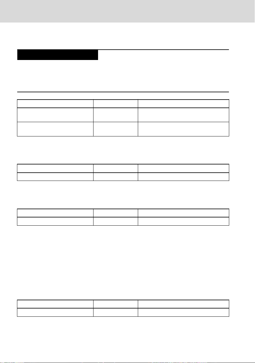
1 About this Documentation
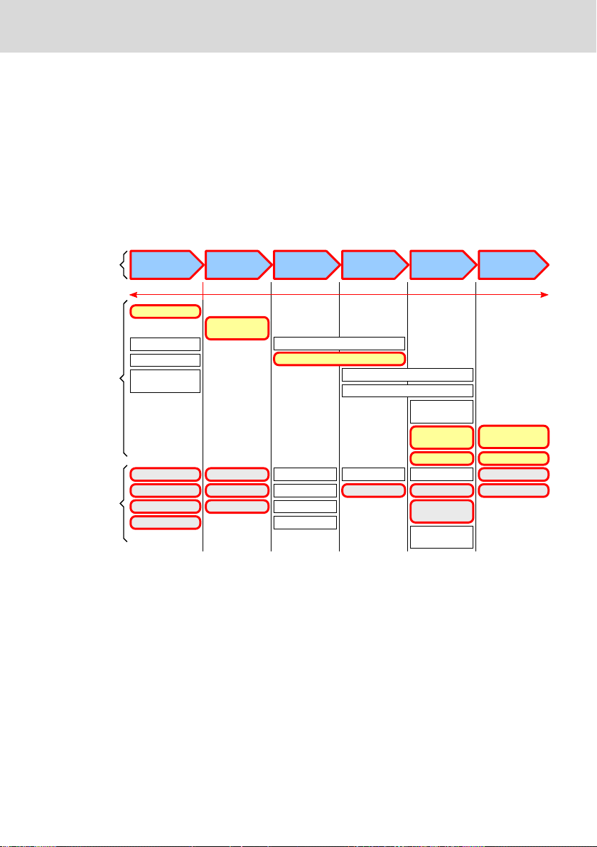
Overview – target groups and product phases
The activities, product phases and target groups that refer to the present docu-
mentation are marked in red color in the following figure.
Example:
In the product phase "Mounting (assembly/installation)", the "mechanic/electri-
cian" can execute the activity "install" using this documentation.
Fig. 1-1: Assigning the present documentation to the target groups, product phases and activities of the target group
Purpose
This document instructs the technical staff of the machine manufacturer on how
to perform the mechanic and electrical installation in a safe way and on how to
commission the device.
Required qualifications: Individual who is able to assess the tasks assigned and
identify possible safety risks owing to qualification in the subject, knowledge
and experience. The individual should also be familiar with the standards and
regulations.
Scope
These operating instructions apply for the following UPS:
DOK-SUPPL*-VAU*01.1X**-IT02-EN-P
1/53
Bosch Rexroth AG
VAU 01.1
About this Documentation
● VAU 01.1U (UPS with USB interface and integrated battery, type designation
code VAU01.1U-024-024-240-NN, parts number R911171024)
● VAU 01.1U (UPS with RS232 interface and integrated battery, type designa-
tion code VAU01.1S-024-024-240-NN, parts number R911307090)
● VAU 01.1Z (UPS with RS232 interface and integrated 24 V power supply unit,
type designation code VAU01.1Z-Z24-024-60-NN, parts number R911170329)
The type designation code specifications are located on the type plate of the device (see chapter 2.1 "Product Identification" on page 4 and chapter 15.2
"Type Code" on page 45).
Further documents
Title Part number and document type
Rexroth IndraControl
VAP 01
R911339613
Operating Instructions
Power Supply Unit
Tab. 1-1: Power supply unit documentation
VAU 01.1U:
Title Part number and document type
Rexroth IndraControl
VPP 16.3/40.3/60.3
R911339626
Operating Instructions
Panel PC
Rexroth IndraControl
VSP xx.3
R911337705
Operating Instructions
Panel PC
Rexroth IndraControl
VPB 40.3
R911336750
Operating Instructions
Control Cabinet PC
Rexroth IndraControl
V Devices
R911343901
Project Planning Manual
Operating Systems
Tab. 1-2: Further documents for the VAU 01.1U
2/53
DOK-SUPPL*-VAU*01.1X**-IT02-EN-P

VAU 01.1 Bosch Rexroth AG
About this Documentation
VAU 01.1S:
Title Part number and document type
Rexroth IndraControl
VPP 21.1
R911305199
Project Planning Manual
Panel PC
Rexroth IndraControl
VPP 21.2
R911323258
Project Planning Manual
Panel PC
Rexroth IndraControl
VSB 40.1
R911310079
Project Planning Manual
Control Cabinet PC
Rexroth IndraControl
VSP 16.1/40.1
R911308264
Project Planning Manual
Control Cabinet PC
Tab. 1-3: Further documents for the VAU 01.1S
VAU 01.1Z:
Title Part number and document type
Rexroth IndraControl
VPP 21.1
R911305199
Project Planning Manual
Panel PC
Rexroth IndraControl
VPP 21.2
R911323258
Project Planning Manual
Panel PC
Tab. 1-4: Further documents for the VAU 01.1Z
Terms and Abbreviations
Designation
Explanation
UPS Uninterruptible Power Supply. The UPS is used for timely-limited volt-
age supply of the connected device if the voltage supply (DC 24 V)
fails.
UPS time The UPS time is the time period in which the connected device is provi-
ded with output voltage of the UPS – after switching off of the input
voltage.
UPS operation Signal to the connected PC that the UPS is in the buffer mode and that
the supply voltage "24V Out" switches off after a set time.
DOK-SUPPL*-VAU*01.1X**-IT02-EN-P
3/53
6
5
4
1
2
3
7
8
9
10
11
14
13
U IN 24VDC OUT 24VDC
MNR: R911171024 GA1
7261
IND.CONT.EQ 17YB
15
12
VAU01.1U-024-024-240-NN
Bosch Rexroth Electric Drives and Controls GmbH
Bgm.-Dr.-Nebel-Str .2, 97816 Lohr a. Main
Made in Germany
IN: IN 12A OUT 10A
N:
I-C-B-H-T-V FD: 12W22
SN: 008580929
Bosch Rexroth AG
Product Identification and Scope of Delivery
VAU 01.1
Time delay This time delay prevents that "UPS operation" is signalled to the con-
nected PC and initiated during the first 120 seconds after switching on
if the input voltage is switched off within these 120 seconds.
UPS-NT Control software The UPS-NT control software is used to monitor and control the UPS.
The software has to be installed on the PC, to which the UPS is connected.
Shutdown delay time The "Shutdown Delay Time" is the time which the shutdown of the con-
nected PC is delayed, which is set in the UPS-NT software. The user
can backup the data during this time.
Shutdown Shutdown of the PC
USB Universal Serial Bus. Serial bus system to connect a computer to exter-
nal devices
Tab. 1-5: Terms and abbreviations used
Customer feedback
Customer requests, comments or suggestions for improvement are of great im-
portance to us. Please email your feedback on the documentations to Feed-
back.Documentation@boschrexroth.de. Directly insert comments in the elec-
tronic PDF document and send the PDF file to Bosch Rexroth.
2
Product Identification and Scope of Delivery
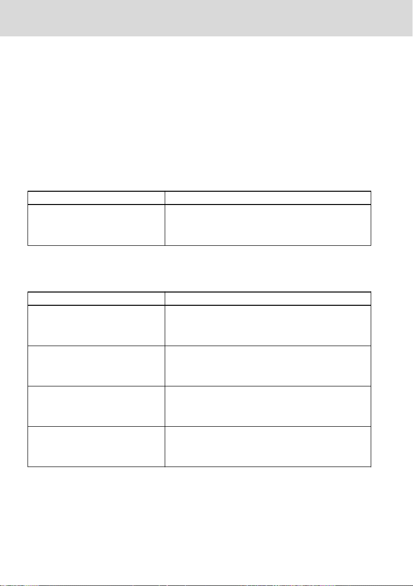
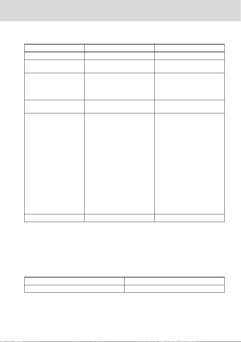
2.1 Product Identification
The type plate is located on the upper side of the device.
Logotype
1
2 Division or plant number
3 Type code (type designation code)
4 Part number
5 State of revision
4/53
6 Nominal voltage
7 Nominal current
8 CE mark
9 Underwriters Laboratories Inc. mark
10 Designation of origin
DOK-SUPPL*-VAU*01.1X**-IT02-EN-P
Burns and chemical burns due to wrong
battery treatment!
CAUTION
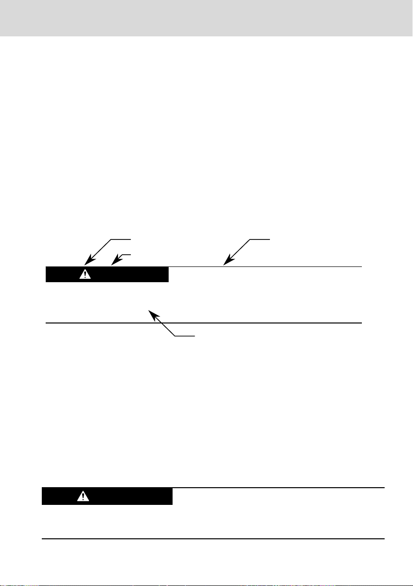
Safety alert symbol
Signal word
Consequences and
source of danger
Avoiding danger
Do not open the batteries and do not heat them over 80 °C.
DANGER
VAU 01.1
Bosch Rexroth AG
Using the Safety Instructions
11 Date of manufacture (yyWww)
12 Serial number as barcode
13 Serial number
Fig. 2-1: Type plate, example
14 Test marking
15 Company address
2.2 Scope of Delivery
● UPS
● Safety instructions
● always one connector for X1S1 and X1S2
3 Using the Safety Instructions
3.1 Safety Instructions – Structure
The safety instructions are structured as follows:
Fig. 3-1: Safety instructions – Structure
3.2 Explaining Signal Words and Safety Alert Symbol
The safety instructions in this documentation contain specific signal words (danger, warning, caution, notice) and, if necessary, a safety alert symbol (according
to ANSI Z535.6-2006).
The signal word is meant to draw the reader's attention to the safety instruction
and signifies the degree of danger.
The safety alert symbol (a triangle with an exclamation point), which precedes
the signal words danger,warning and caution is used to alert the reader to personal injury hazards.
In case of non-compliance with this safety instruction, death or serious injury
will occur.
DOK-SUPPL*-VAU*01.1X**-IT02-EN-P
5/53
WARNING
CAUTION
NOTICE
Bosch Rexroth AG
Intended Use
In case of non-compliance with this safety instruction, death or serious injury
can occur.
In case of non-compliance with this safety instruction, minor or moderate injury
could occur.
In case of non-compliance with this safety instruction, property damage could
occur.
VAU 01.1
3.3 Symbols Used
Notes are displayed as follows:
This is a note.
Tips are displayed as follows:
This is a tip.
4 Intended Use
The Bosch Rexroth VAU 01.1U, VAU 01.1S and VAU 01.1Z are Uninterruptible
Power Supplies (UPS).
6/53
DOK-SUPPL*-VAU*01.1X**-IT02-EN-P

NOTICE
VAU 01.1 Bosch Rexroth AG
Spare Parts, Accessories and Wear Parts
Danger of destruction of the device if not expressly stated accessories, mounting parts and
other components, cables, lines, software and
firmware are used.
The UPS may be used only as intended and with the accessories, mounting
parts and other components specified in this documentation. Components that
are not expressly mentioned must neither be attached nor connected. The same
applies to cables and lines.
Operation must only be carried out with the hardware component configurations and combinations that are expressly specified and with the software and
firmware indicated and specified in the respective documentation and functional descriptions.
The UPS can be used for the following panel PCs and control cabinet PCs:
VAU 01.1U
● Panel PC Rexroth IndraControl VPP 15.3/16.3/40.3/60.3
● Panel PC Rexroth IndraControl VPP 16.3/40.3/60.3
● Panel PC Rexroth IndraControl VSP 16.3/40.3/60.3
● Control cabinet PC Rexroth IndraControl VSB 40.3
VAU 01.1S
● Panel PC Rexroth IndraControl VPP 21.1
● Panel PC Rexroth IndraControl VPP 21.2
● Panel PC Rexroth IndraControl VSP 16.1/40.1/60.3
VAU 01.1Z
● Panel PC Rexroth IndraControl VPP 21.1
● Panel PC Rexroth IndraControl VPP 21.2
The UPS may only be operated under the mounting and installation conditions,
the position, and the ambient conditions (temperature, degree of protection,
humidity, EMC etc.) specified in the related documentation.
5
Spare Parts, Accessories and Wear Parts
5.1 External 24 V Power Supply Unit
Ordering code Part number Description
VAP01.1H-W23-024-010-NN R911171065 External 24 V power supply unit for UPS
and IndraControl V devices
Tab. 5-1: Order data, 24 V power supply unit for UPS and IndraControl V devices
DOK-SUPPL*-VAU*01.1X**-IT02-EN-P
7/53
NOTICE
Bosch Rexroth AG
Spare Parts, Accessories and Wear Parts
VAU 01.1
5.2 USB Cable with Increased Noise Immunity for VAU 01.1U
If the UPS is used in noisy environment, malfunctions are possible.
Use only USB cables with high noise immunity for the connection between control cabinet PC and uninterruptible power supply (VAU 01.1 U) with communication interface.
Ordering code Part number Description
RKB0050/001,0 R911172944 USB connecting cable with increased noise
RKB0050/003,0 R911172945 USB connecting cable with increased noise
Tab. 5-2: Order data, USB connecting cable with increased noise immunity
immunity; length 1 m
immunity; length 3 m
5.3 RS232 Cable for VAU 01.1S and VAU 01.1Z
Ordering code Part number Description
KABEL 9POL USV 3m 10700089307 RS232 cable, 3 m
Tab. 5-3: Order data RS232 cable
5.4 End Clamp
Ordering code Part number Description
SUP-M01-ENDHALTER/PA R911172352 End clamp (2 pieces)
Tab. 5-4: Order data, end clamp
5.5 Wear Parts
Wear parts are not subject to any warranty.
Battery for VAU 01.1U and VAU 01.1S
The service life of the battery is limited. The service life of the battery is approxi-
mately ten years at +25 °C. The service life is halved with each 10 °C temperature rise. For storing the VAU 01.1U and VAU 01.1S, observe also chapter 14.4
"VAU 01.1U and VAU 01.1S – Storage" on page 44.
Ordering code
AKKU 24V/2,5Ah 1070923287 Battery
Tab. 5-5: Order data, battery
8/53
Part number Description
DOK-SUPPL*-VAU*01.1X**-IT02-EN-P
VAU 01.1 Bosch Rexroth AG
Technical Data
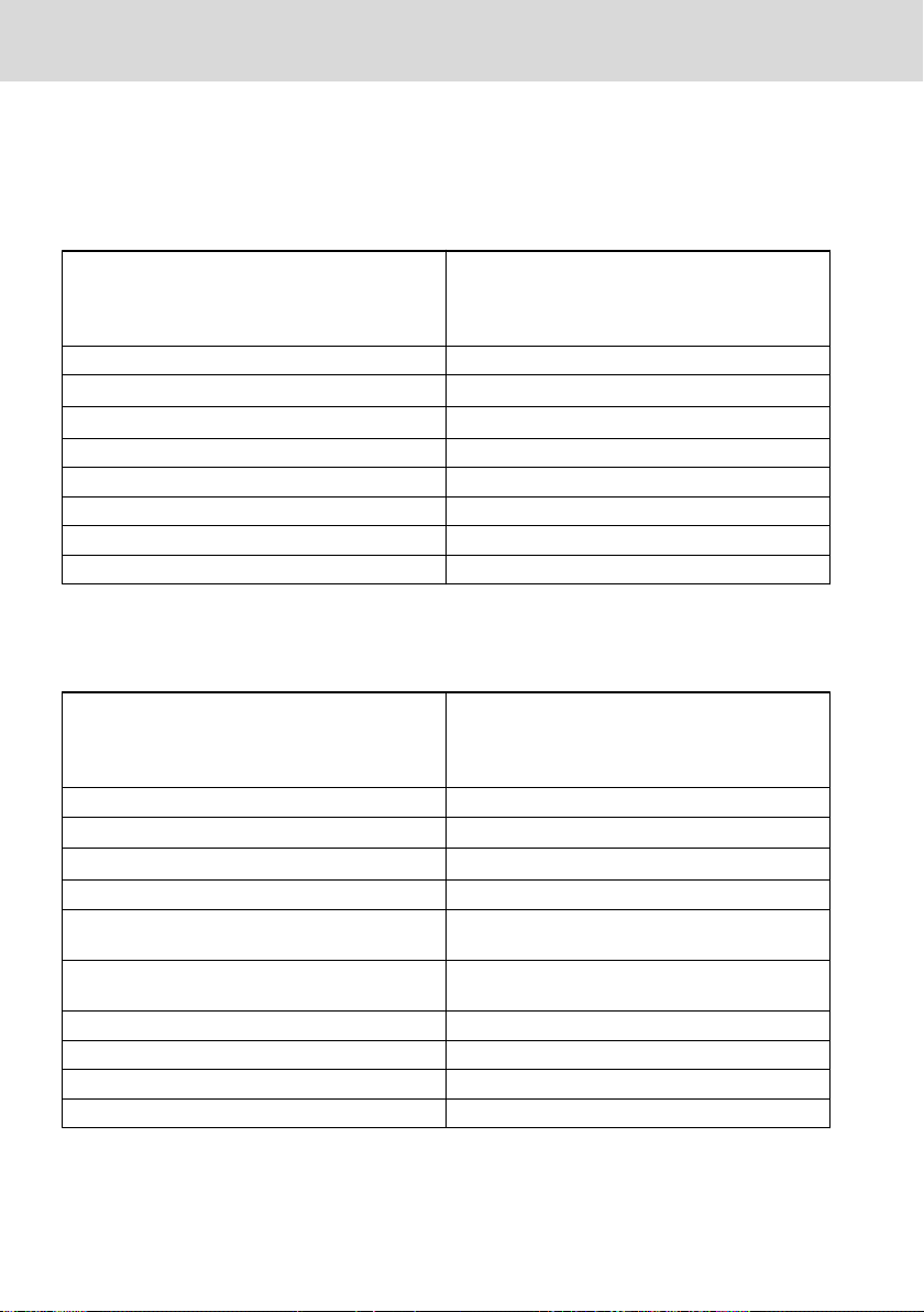
6 Ambient Conditions
In operation Storage and transport
Ambient temperature +5 ℃ to +45 ℃ -20 ℃ to +60 ℃
Maximum temperature gradi-
ent
Relative humidity Climatic class 3K3 according to
Air pressure Up to 3000 m above sea level acc.
Mechanical strength Maximum vibration
Degree of pollution 2 2
Temporal temperature changes up
to 3 ℃ per minute
EN 60721, condensation not permissible.
Max. 80 % humidity at 25 °C
to EN 61131-2
Frequency range:
10 Hz to 150 Hz
Excursion:
0.075 mm at 10 Hz to 57 Hz
Acceleration:
1 g at 57 Hz to 150 Hz
Test duration for each axis:
10 frequency cycles
Frequency sweep rate:
1 octave/min
According to EN 60068-2-6, test
Fc
Temporal temperature changes up
to 3 ℃ per minute
Climatic class 3K3 according to
EN 60721, condensation not permissible.
Max. 80 % humidity at 25 °C
Up to 3000 m above sea level acc.
to EN 61131-2
Maximum shock:
15 g according to EN 60
068-2-27, no disturbance of the
function
Tab. 6-1: Ambient Conditions
7
Technical Data
7.1 VAU 01.1U/VAU 01.1S
7.1.1 Degree of Protection and Weight
Enclosure rating IP 20
Weight 3.5 kg
Tab. 7-1: Degree of protection and weight
DOK-SUPPL*-VAU*01.1X**-IT02-EN-P
9/53
Bosch Rexroth AG
Technical Data
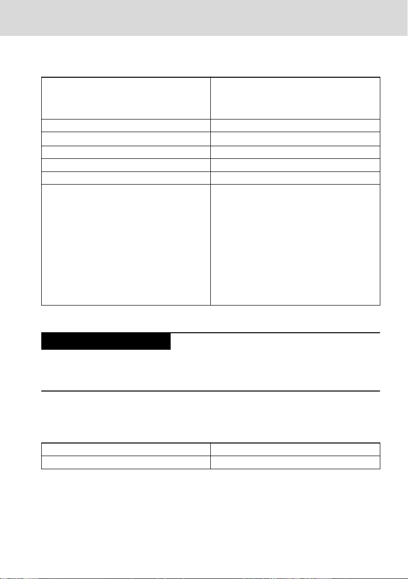
7.1.2 Input and Output Voltage
Input voltage
VAU 01.1U
VAU 01.1
Nominal input voltage DC 24 V (use a 24 V power supply unit according
to DIN EN 60742, classification VDE 0551, for example the power supply unit VAP01.1H-
W23-024-010-NN, part number R911171065)
Input voltage range DC 24 V +20 %, -15 %
Emitted interference and surge immunity U
Current consumption for U
N
= 35 V (for t < 100 ms)
max
Max. 12 A (2 A for charging the battery)
Input fuse No
Switch-on threshold 22 V ±5 %
Switch-off threshold 19 V ±5 %
Max. power consumption 288 W (48 W for charging the battery)
Reverse voltage protection Yes
Tab. 7-2: Input voltage 24 V
VAU 01.1S
Nominal input voltage DC 24 V (use a 24 V power supply unit according
to DIN EN 60742, classification VDE 0551, for ex-
ample the power supply unit VAP01.1H-
W23-024-010-NN, part number R911171065)
Input voltage range DC 24 V +20 %, -15 %
Emitted interference and surge immunity U
Current consumption for U
N
= 35 V (for t < 100 ms)
max
Max. 12 A (2 A for charging the battery)
Input fuse No
Voltage rise of the supply voltage when switchingonMax. 500 ms (0 V to UN)
Voltage rise of the supply voltage when switching
Max. 500 ms (UN to 0 V)
off
Switch-on threshold 15.5 V ±5 %
Switch-off threshold 20.2 V ±5 %
Max. power consumption 288 W (48 W for charging the battery)
Reverse voltage protection No
Tab. 7-3: Input voltage 24 V
10/53
DOK-SUPPL*-VAU*01.1X**-IT02-EN-P
NOTICE
VAU 01.1 Bosch Rexroth AG
Technical Data
Output voltage
Nominal output voltage DC 24 V (use a 24 V power supply unit according
to DIN EN 60742, classification VDE 0551, for example the power supply unit VAP01.1H-
W23-024-010-NN, part number R911171065)
Output voltage range DC 24 V +20 %, -15 %
Current output at U
N
Maximum 10 A
Switching time < 1 ms
Bridging time 3 minutes max.
Max. output power 240 W
Short-circuit protection VAU 01.1S: No
VAU 01.1U (from technical index GC1): Yes
Note:
A short circuit in the UPS VAU 01.1U results in an
immediate switch-off of the output voltage. A new
switch on can only take place after switching
off/on of the input voltage. To load capacitive
loads, a cut-out delay of 300 ms during the start-
ing operation is incorporated. This results in a
maximum permissible capacitive load of 5600 μF
at 5 A resistive load during the starting operation
Tab. 7-4: Output voltage 24 V
Overheating and possible damage to the UPS if
the max. power consumption is exceeded.
The max. power consumption of the connected control cabinet PC or panel PC
must not exceed the max. output power of the UPS of 240 W.
7.2
VAU 01.1Z
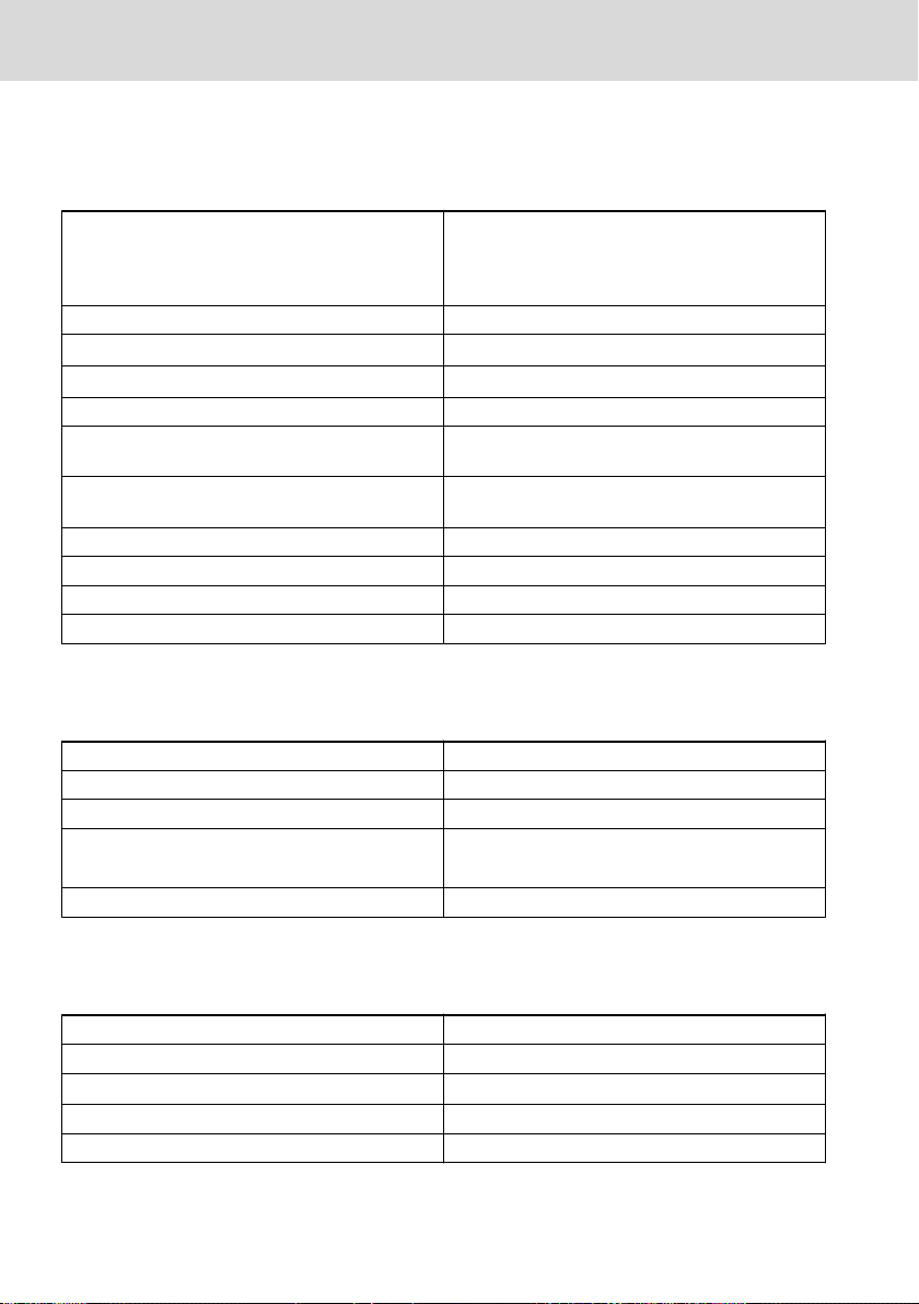
7.2.1 Degree of Protection and Weight
Enclosure rating IP 20
Weight 1 kg
Tab. 7-5: Degree of protection and weight
DOK-SUPPL*-VAU*01.1X**-IT02-EN-P
11/53
Bosch Rexroth AG
Technical Data
7.2.2 Input and Output Voltage
+24V input voltage
VAU 01.1
Nominal input voltage DC 24 V (use a 24 V power supply unit according
to DIN EN 60742, classification VDE 0551, for example the power supply unit VAP01.1H-
W23-024-010-NN, part number R911171065)
Input voltage range DC 24 V +20 %, -15 %
Emitted interference and surge immunity U
Current consumption for U
N
= 35 V (for t < 100 ms)
max
Maximum 2.5 A
Input fuse No
Voltage rise of the supply voltage when switchingonMax. 500 ms (0 V to UN)
Voltage rise of the supply voltage when switching
Max. 500 ms (UN to 0 V)
off
Switch-on threshold 15.5 V ±5 %
Switch-off threshold 20.2 V ±5 %
Max. power consumption 60 W
Reverse voltage protection No
Tab. 7-6: Input voltage 24 V
115/230 VAC input voltage
Nominal input voltage
115/230 VAC
Input voltage range 85 – 264 VAC
Input frequency 47 – 63 Hz
Current consumption for U
N
115 VAC = 1.00 A typ.
230 VAC = 0.60 A typ.
Recommended protection 5 A
Tab. 7-7: 115/230 VAC input voltage
Output voltage
Nominal output voltage
DC 24 V
Output voltage range DC 24 V +20 %, -15 %
Current output at U
N
Maximum 2.5 A
Switching time < 1 ms
Bridging time 3 minutes max.
12/53
DOK-SUPPL*-VAU*01.1X**-IT02-EN-P
 Loading...