

Bosch REXROTH IndraControl VAM 42.1, REXROTH IndraControl VAM 12.1 Project Planning Manual
Electric Drives
and Controls Pneumatics
Hydraulics
Linear Motion and
Assembly Technologies
Rexroth IndraControl
VAM 12.1/42.1
Machine Control Panels
Project Planning Manual
Service
R911327985
Edition 02

Bosch Rexroth AG DOK-SUPPL*-VAM*XX.1***-PR02-EN-P
Rexroth IndraControl VAM 12.1/42.1 Machine Control Panels
Title
Type of Documentation
Document Typecode
Internal File Reference
Purpose of Documentation
Record of Revision
Copyright
Validity
Published by
Rexroth IndraControl
VAM 12.1/42.1
Machine Control Panels
Project Planning Manual
DOK-SUPPL*-VAM*XX.1***-PR02-EN-P
RS-043d47a2a287bc520a6846a00157fa3f-2-en-US-3
This
documentation describes the VAM 12.1 and VAM 42.1 machine control
panels.
Edition
120-2101-B309-01/EN 05.2009 First edition
120-2101-B309-02/EN 04.2011 Second edition
Release Date Notes
© Bosch Rexroth AG 2009
Copying
this document, giving it to others and the use or communication of the
contents thereof without express authority, are forbidden. Offenders are liable
for the payment of damages. All rights are reserved in the event of the grant of
a patent or the registration of a utility model or design (DIN 34-1).
The specified data is for product description purposes only and may not be
deemed to be guaranteed unless expressly confirmed in the contract. All rights
are reserved with respect to the content of this documentation and the availa‐
bility of the product.
Bosch Rexroth AG
Bgm.-Dr.-Nebel-Str. 2 ■ 97816 Lohr am Main, Germany
Phone +49 (0)93 52/ 40-0 ■ Fax +49 (0)93 52/ 40-48 85
http://www.boschrexroth.com/
Development Compact Control JK (CS)
Note
This document has been printed on chlorine-free bleached paper.

DOK-SUPPL*-VAM*XX.1***-PR02-EN-P
Rexroth IndraControl VAM 12.1/42.1 Machine Control Panels
Bosch Rexroth AG I/93
Table of Contents
Table of Contents
Page
1 System Presentation...................................................................................................... 7
1.1
1.2 VAM 12.1/VAM 42.1 Standard Variants................................................................................................. 7
1.2.1 Standard Variants Overview................................................................................................................ 7
1.2.2 Rear Side............................................................................................................................................. 7
1.2.3 Front View Machine Control Panel: Overview..................................................................................... 8
1.2.4 Front View of the VAM 12.1 Machine Control Panel, Standard Variant.............................................. 8
1.2.5 Front View of the VAM 42.1 Machine Control Panel, Standard Variant.............................................. 9
1.3 Customized Variant................................................................................................................................ 9
1.3.1 General Information............................................................................................................................. 9
1.3.2 Front View Machine Control Panel - Customized Variant (Overview)............................................... 10
1.3.3 Front View Machine Control Panel VAM 12.1, Customized Variant.................................................. 10
1.3.4 Front View Machine Control Panel VAM 42.1, Customized Variant.................................................. 12
Brief Description..................................................................................................................................... 7
2 Important Instructions on Use ..................................................................................... 13
2.1 Appropriate Use ................................................................................................................................... 13
2.1.1 Introduction........................................................................................................................................ 13
2.1.2 Areas of Use and Application............................................................................................................ 13
2.2 Inappropriate Use................................................................................................................................. 14
3 Safety Instructions for Electric Drives and Controls..................................................... 15
3.1 Definitions of Terms.............................................................................................................................. 15
3.2 General Information.............................................................................................................................. 16
3.2.1 Using the Safety Instructions and Passing Them on to Others......................................................... 16
3.2.2 Requirements for Safe Use............................................................................................................... 16
3.2.3 Hazards by Improper Use.................................................................................................................. 17
3.3 Instructions with Regard to Specific Dangers....................................................................................... 19
3.3.1 Protection Against Contact With Electrical Parts and Housings........................................................ 19
3.3.2 Protective Extra-Low Voltage as Protection Against Electric Shock ................................................ 20
3.3.3 Protection Against Dangerous Movements....................................................................................... 20
3.3.4 Protection Against Magnetic and Electromagnetic Fields During Operation and Mounting.............. 22
3.3.5 Protection Against Contact With Hot Parts........................................................................................ 22
3.3.6 Protection During Handling and Mounting......................................................................................... 23
3.3.7 Battery Safety.................................................................................................................................... 23
3.3.8 Protection Against Pressurized Systems........................................................................................... 24
3.4 Explanation of Signal Words and the Safety Alert Symbol................................................................... 24
4 Technical Data............................................................................................................. 27
4.1 Basic Device......................................................................................................................................... 27
4.2 Switching Elements, Pushbuttons........................................................................................................ 28
4.3 EMERGENCY STOP............................................................................................................................ 29
4.4 VAC 30.2 Connection Module for VEH 30.1, VEH 30.2 or VCH 08.1 Hand-Held Terminal................. 30
4.5 Euchner EKS, Electronic-Key-System.................................................................................................. 30

II/93
Table of Contents
4.5.1 Technical Data................................................................................................................................... 30
4.6
4.7 Standards............................................................................................................................................. 31
4.7.1 Used Standards................................................................................................................................. 31
4.7.2 CE Marking........................................................................................................................................ 32
4.7.3 UL and CSA certified......................................................................................................................... 33
4.8 Compatibility Test................................................................................................................................. 33
Bosch Rexroth AG DOK-SUPPL*-VAM*XX.1***-PR02-EN-P
Rexroth IndraControl VAM 12.1/42.1 Machine Control Panels
Page
Ambient Conditions............................................................................................................................... 31
Declaration of Conformity .............................................................................................................. 32
5 Dimensions and Installation......................................................................................... 35
5.1 General Information.............................................................................................................................. 35
5.2 Housing Dimensions VAM 12.1, Standard Variant............................................................................... 35
5.2.1 VAM 12.1 Front View......................................................................................................................... 35
5.2.2 VAM 12.1 Side View.......................................................................................................................... 36
5.2.3 VAM 12.1 Top View........................................................................................................................... 36
5.2.4 VAM 12.1 Rear View......................................................................................................................... 37
5.3 Housing Dimensions VAM 12.1, Customized Variant .......................................................................... 37
5.4 Housing Dimensions VAM 42.1, Standard Variant............................................................................... 38
5.4.1 VAM 42.1 Front View......................................................................................................................... 38
5.4.2 VAM 42.1 Side View.......................................................................................................................... 39
5.4.3 VAM 42.1 Top View........................................................................................................................... 39
5.4.4 VAM 42.1 Rear View......................................................................................................................... 40
5.5 Housing Dimensions VAM 42.1, Customized Variant .......................................................................... 40
5.6 Installation............................................................................................................................................. 40
5.6.1 Installation Notes............................................................................................................................... 40
5.6.2 Mounting Cut-Out.............................................................................................................................. 41
5.6.3 Mounting Dimensions VAM 12.1....................................................................................................... 41
5.6.4 Mounting Dimensions VAM 42.1....................................................................................................... 42
6 Module Design............................................................................................................. 43
6.1 General Information.............................................................................................................................. 43
6.1.1 General Information........................................................................................................................... 43
6.1.2 Labeling Templates for Slide-In Strips............................................................................................... 43
6.2 Modules ............................................................................................................................................... 43
6.2.1 EMERGENCY-STOP Button............................................................................................................. 43
6.2.2 Keypads ............................................................................................................................................ 44
6.2.3 Override VD....................................................................................................................................... 45
6.2.4 Equipment with 22.5 mm Switching Elements (Control and Indicator Units)..................................... 46
6.2.5 Combined Slot for 16 mm and 22.5 mm Switching Element............................................................. 47
6.2.6 Euchner EKS (Electronic-Key-System)............................................................................................. 48
General Information........................................................................................................................ 48
Pin Assignment Euchner EKS-FSA................................................................................................ 48
DIP Switch Settings Euchner EKS-FSA......................................................................................... 49
6.2.7 Connection Module VAC 30.2........................................................................................................... 49
General Information........................................................................................................................ 49

DOK-SUPPL*-VAM*XX.1***-PR02-EN-P
Rexroth IndraControl VAM 12.1/42.1 Machine Control Panels
Enabling Button of the Hand-Held Terminals IndraControl VEH 30.1, 30.2 or VCH 08.1.............. 49
STOP Button of the Hand-Held Terminals IndraControl VEH 30.1, VEH 30.2 or VCH 08.1.......... 50
6.2.8
6.2.9 Pushbuttons Customized Variant "D1".............................................................................................. 51
Pushbuttons on the VAM12.1-PB-NF-NN-TB-VD-NN-1608-NN and VAM42.1-PB-NF-NN-TB-VD-
NN-1608-NN...................................................................................................................................... 50
Bosch Rexroth AG III/93
Table of Contents
Page
7 Interfaces..................................................................................................................... 53
7.1 Connector Panel................................................................................................................................... 53
7.2 Protective Earth Terminal..................................................................................................................... 53
7.3 X10: Current and Voltage Supply ........................................................................................................ 53
7.4 X71: Fieldbus Interface PROFIBUS DP X71........................................................................................ 57
7.4.1 General Information........................................................................................................................... 57
7.4.2 Pin Assignment.................................................................................................................................. 58
7.5 X21, X22, X11: Digital 24 V Inputs and Outputs................................................................................... 58
7.5.1 General Information........................................................................................................................... 58
7.5.2 Pin Assignment (3 × 8-Pin Weidmüller Connector, 3.5 Pin Spacing)................................................ 59
7.5.3 Characteristics of the Digital Inputs................................................................................................... 60
7.5.4 Characteristics of the Digital Outputs................................................................................................ 60
7.6 Wiring of the Pushbuttons and of the EMERGENCY STOP button for Customized Device Variant "D1"
.............................................................................................................................................................. 61
7.6.1 Wiring of the Pushbuttons and of the EMERGENCY STOP Button VAM 12.1, Device Variant "D1"....
61
7.6.2 Wiring of the Pushbuttons and of the EMERGENCY STOP Button VAM 42.1, Device Variant "D1"....
62
7.7 X81: Connection for External Hand-Held Terminal............................................................................... 62
7.7.1 General Information........................................................................................................................... 62
7.7.2 Pin Assignment (25-Pin Female Connector Strip, D-SUB................................................................. 63
7.8 X82: Connection for Internal Handwheel.............................................................................................. 64
7.8.1 General Information........................................................................................................................... 64
7.8.2 Pin Assignment (6-Pin Weidmüller Connector, 3.5 Pin Spacing)...................................................... 64
7.9 Connecting a Hand-Held Terminal IndraControl VEH 30.1, VEH 30.2 or VCH 08.1............................ 64
7.9.1 Overview............................................................................................................................................ 64
7.9.2 Pin Assignment of the VAC 30.2 Connection Module ...................................................................... 65
7.9.3 X1: DC 24 V Voltage Supply VAC 30.2............................................................................................. 66
7.9.4 X2.1: STOP Button VAC 30.2 ........................................................................................................... 67
Pin Assignment............................................................................................................................... 67
7.9.5 X2.2: Enabling Button VAC 30.2 ...................................................................................................... 67
Pin Assignment X2.2...................................................................................................................... 67
Wiring the Enabling Button............................................................................................................. 68
7.9.6 X3: Ethernet Interface VAC 30.2 ...................................................................................................... 68
7.9.7 Personality Function.......................................................................................................................... 69
8 Maintenance and Commissioning................................................................................ 71
8.1 Maintenance......................................................................................................................................... 71
8.2 Torques and Stripping Length.............................................................................................................. 71
8.3 GSD File............................................................................................................................................... 71

IV/93
Table of Contents
8.4 PROFIBUS DP Address Settings......................................................................................................... 71
8.5
8.6 Status Displays..................................................................................................................................... 72
8.6.1 General Information........................................................................................................................... 72
8.6.2 System Stop...................................................................................................................................... 74
8.7 Address Assignment............................................................................................................................. 75
8.7.1 Keypads............................................................................................................................................. 75
8.7.2 Module Override VD.......................................................................................................................... 76
8.7.3 Digital 24 V Inputs and Outputs......................................................................................................... 78
8.7.4 External Hand-Held Terminal............................................................................................................ 78
8.7.5 Internal Handwheel............................................................................................................................ 79
8.8 Commissioning the Hand-Held Terminals IndraControl VEH 30.1, VEH 30.2 or VCH 08.1................. 79
8.9 Configuration Specifications................................................................................................................. 80
8.9.1 General Information........................................................................................................................... 80
8.9.2 VAM12.1-PB-NF-NN-TB-VD-NN-1608-NN / VAM12.1-PB-NF-AB-TB-VD-EK-1608-D1................... 80
8.9.3 VAM12.1-PB-NF-AB-TB-NN-EK-1608-D1......................................................................................... 80
8.9.4 VAM42.1-PB-NF-NN-TB-VD-NN-1608-NN / VAM42.1-PB-NF-AB-TB-VD-EK-1608-D1................... 80
8.9.5 VAM42.1-PB-NF-AB-TB-NN-EK-1608-D1......................................................................................... 81
8.10 Sample Configuration Using IndraLogic............................................................................................... 81
Bosch Rexroth AG DOK-SUPPL*-VAM*XX.1***-PR02-EN-P
Rexroth IndraControl VAM 12.1/42.1 Machine Control Panels
Page
Baud Rate Setting................................................................................................................................. 72
General Information........................................................................................................................ 75
PROFIBUS DP Module for Keypad 1 (GSD File)........................................................................... 76
PROFIBUS DP Module for Keypad 2 (GSD File)........................................................................... 76
General Information........................................................................................................................ 76
Gray Code Table for 24-Stage Feed Override............................................................................... 76
Gray Code Table for 16-Stage Spindle Override............................................................................ 77
PROFIBUS DP Module (GSD File)................................................................................................ 78
General Information........................................................................................................................ 78
PROFIBUS DP Module (GSD File)................................................................................................ 78
General Information........................................................................................................................ 78
PROFIBUS DP Module (GSD File)................................................................................................ 78
General Information........................................................................................................................ 79
PROFIBUS DP Module (GSD File)................................................................................................ 79
9 Environmental Protection and Disposal ...................................................................... 83
9.1 Environmental Protection...................................................................................................................... 83
9.2 Disposal................................................................................................................................................ 83
10 Ordering Information.................................................................................................... 85
10.1 Type Designation Code........................................................................................................................ 85
10.2 Accessories.......................................................................................................................................... 86
10.2.1 Plugs and Ready-Made Cables......................................................................................................... 86
10.3 Spare Parts........................................................................................................................................... 87
11 Service and Support.................................................................................................... 89

DOK-SUPPL*-VAM*XX.1***-PR02-EN-P
Rexroth IndraControl VAM 12.1/42.1 Machine Control Panels
Index............................................................................................................................ 91
Bosch Rexroth AG V/93
Table of Contents
Page

VI/93
Bosch Rexroth AG DOK-SUPPL*-VAM*XX.1***-PR02-EN-P
Rexroth IndraControl VAM 12.1/42.1 Machine Control Panels

DOK-SUPPL*-VAM*XX.1***-PR02-EN-P
Rexroth IndraControl VAM 12.1/42.1 Machine Control Panels
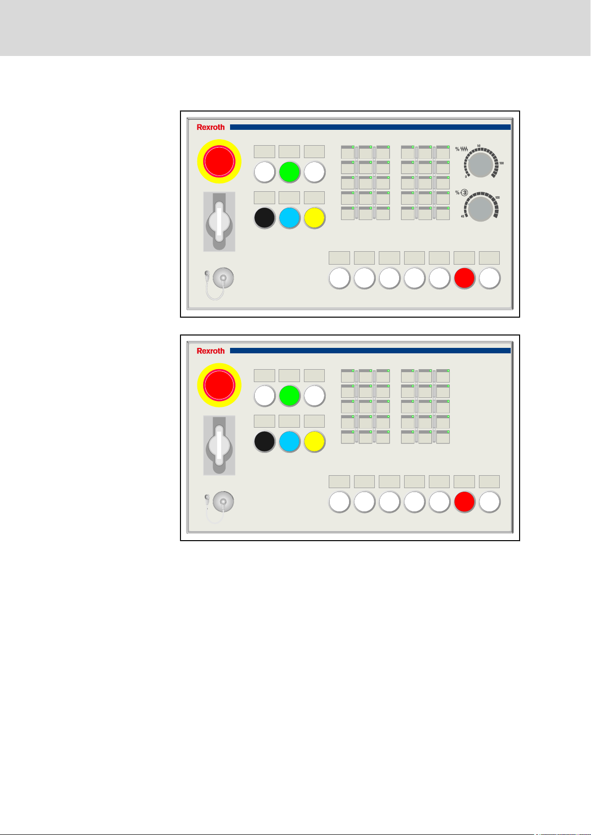
1 System Presentation
Bosch Rexroth AG 7/93
System Presentation
1.1
Brief Description
Machine control panels complete operator and visualization terminals and are
used to select the operation modes as well as to operate the machine manually.
The machine control panels feature operating elements, e. g. keys with LED
displays, rotary switches for feed and spindle override, EMERGENCY STOP
button, cut-outs for 22.5 mm control and indicator units as well as a connection
for a hand-held terminal.
The VAM 12.1/VAM 42.1 machine control panels have been specially designed
for the use in combination with devices of the VPB, VPP, Vxx product family
and are adapted to the design of these devices. The VAM 12.1 width corre‐
sponds to the VSP 16 width. The VPP 16 and VAM 42.1 width corresponds to
the VSP 40 and VPP 40 width.
VAM devices are machine operator panels for CNC machines with PROFIBUS
connection.
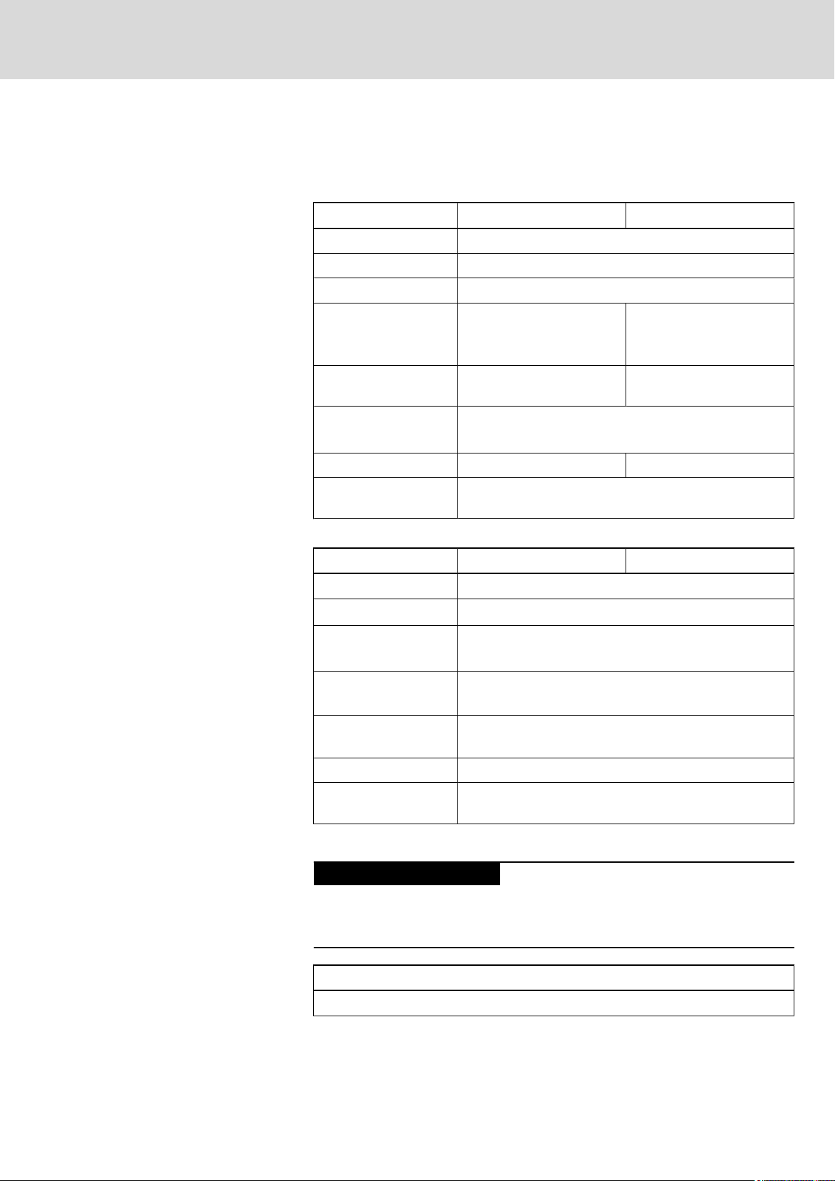
1.2 VAM 12.1/VAM 42.1 Standard Variants
1.2.1 Standard Variants Overview
The VAM 12.1/VAM 42.1 machine control panels feature the following ele‐
ments:
2 keypads
with keys that
might be free‐
ly labeled and
programmed
Cut-outs for
mounting
22.5 mm
control and
indicator
units
Further elements Order number
and type desig‐
nation code
1.2.2 Rear Side
VAM 12.1 30 illuminated
keys
VAM 42.1 30 illuminated
keys
Fig.1-1: VAM 12.1/VAM 42.1 Standard Variants
9 cut-outs ● EMERGENCY
STOP button
●
4 pushbuttons
● 2 rotary switches
for feed and spin‐
dle override
10 cut-outs ● EMERGENCY
STOP button
●
6 pushbuttons
● 2 rotary switches
for feed and spin‐
dle override
R911171651
VAM12.1-PBNF-NN-TB-VDNN-1608-NN
R911171654
VAM42.1-PBNF-NN-TB-VDNN-1608-NN
The following components are located on the rear side of the VAM 12.1/
VAM 42.1:
● A 25-pin connector for connecting a hand-held terminal (e.g. Euchner HBA
098404)
● 6-pin connector to connect a handwheel
● 16 digital 24 V inputs.
IndraControl V
1 2
3
4
6
5
IndraControl V
8/93
System Presentation
Bosch Rexroth AG DOK-SUPPL*-VAM*XX.1***-PR02-EN-P
Rexroth IndraControl VAM 12.1/42.1 Machine Control Panels
● 8 digital 24 V outputs
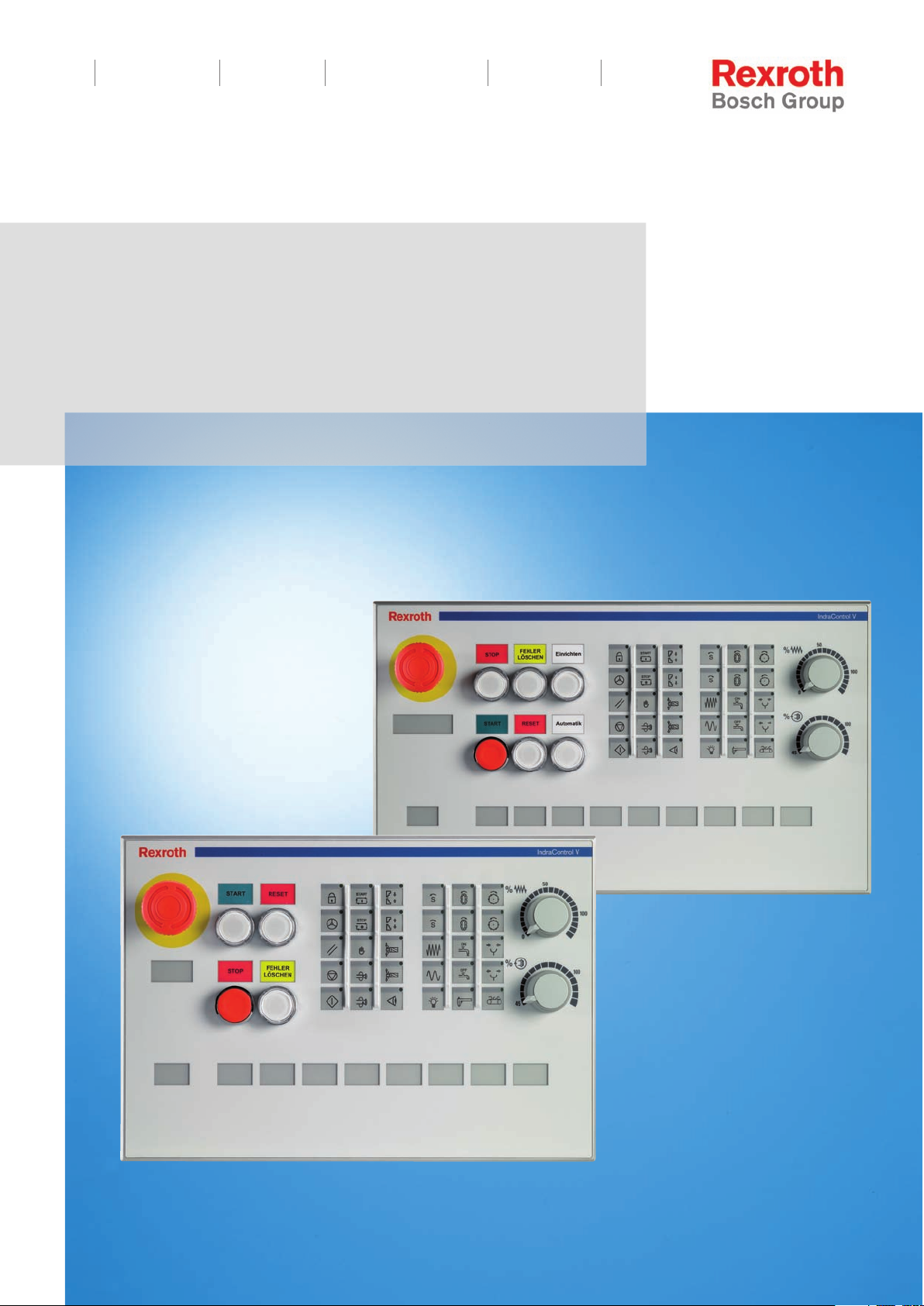
1.2.3
Front View Machine Control Panel: Overview
① EMERGENCY STOP button
② Pushbuttons
③ Keypads with keys that can be freely labeled and programmed
④ Override rotary switch for feed
⑤ Override rotary switch for spindle
⑥ Cut-outs for mounting 22.5 mm control and indicator units
Fig.1-2: Front view machine control panel (standard variant)
1.2.4 Front View of the VAM 12.1 Machine Control Panel, Standard Variant
Fig.1-3: Front view AM12.1-PB-NF-NN-TB-VD-NN-1608-NN
IndraControl V
DOK-SUPPL*-VAM*XX.1***-PR02-EN-P
Rexroth IndraControl VAM 12.1/42.1 Machine Control Panels
Bosch Rexroth AG 9/93
System Presentation
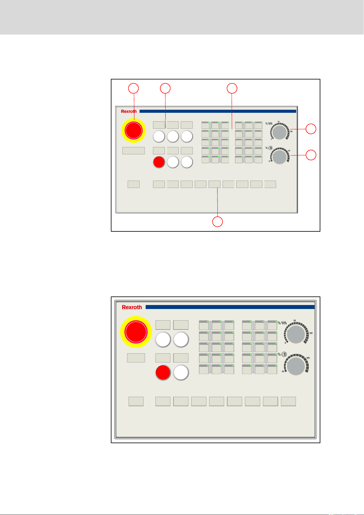
1.2.5 Front View of the VAM 42.1 Machine Control Panel, Standard Variant
contrast to the VAM 12.1, the VAM 42.1 is equipped with six pushbuttons
In
and provides ten cut-outs for 22.5 mm switching elements.
Fig.1-4: VAM42.1-PB-NF-NN-TB-VD-NN-1608-D1
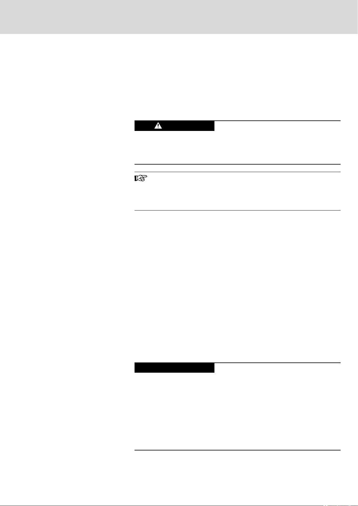
1.3 Customized Variant
1.3.1 General Information
Besides the previously described standard variants of the VAM 12.1/
VAM 42.1, customized variants of the VAM 12.1/VAM 42.1 are available. The
pushbuttons of these machine control panels are equipped and assembled
customer-specifically.
VAM 12.1
Customized
With override
VAM 12.1
Customized
Without over‐
ride
2 keypads with keys that
might be freely labeled
and programmed
30 illuminated keys ● EMERGENCY
30 illuminated keys ● EMERGENCY
Further elements Order number
STOP button
●
10 pushbuttons
● 2 rotary switches
for feed and spin‐
dle override
● VAC 30.2
● Euchner EKS
STOP button
●
10 pushbuttons
● VAC 30.2
● Euchner EKS
and type desig‐
nation code
R911171652
VAM12.1-PBNF-AB-TB-VDEK-1608-D1
R911171653
VAM12.1-PBNF-AB-TB-NNEK-1608-D1

IndraControl V
1 2
3
4
6
5
7
8
10/93
Bosch Rexroth AG DOK-SUPPL*-VAM*XX.1***-PR02-EN-P
System Presentation
Rexroth IndraControl VAM 12.1/42.1 Machine Control Panels
2 keypads with keys that
might be freely labeled
and programmed
VAM 42.1
Customized
With override
VAM 42.1
Customized
Without over‐
ride
Fig.1-5: Customized variants VAM 12.1/VAM 42.1
30 illuminated keys ● EMERGENCY
30 illuminated keys ● EMERGENCY
Further elements Order number
and type desig‐
nation code
R911171655
STOP button
●
13 pushbuttons
● 2 rotary switches
for feed and spin‐
dle override
● VAC 30.2
● Euchner EKS
STOP button
●
13 pushbuttons
● VAC 30.2
● Euchner EKS
VAM42.1-PBNF-AB-TB-VDEK-1608-D1
R911171656
VAM42.1-PBNF-AB-TB-NNEK-1608-D1
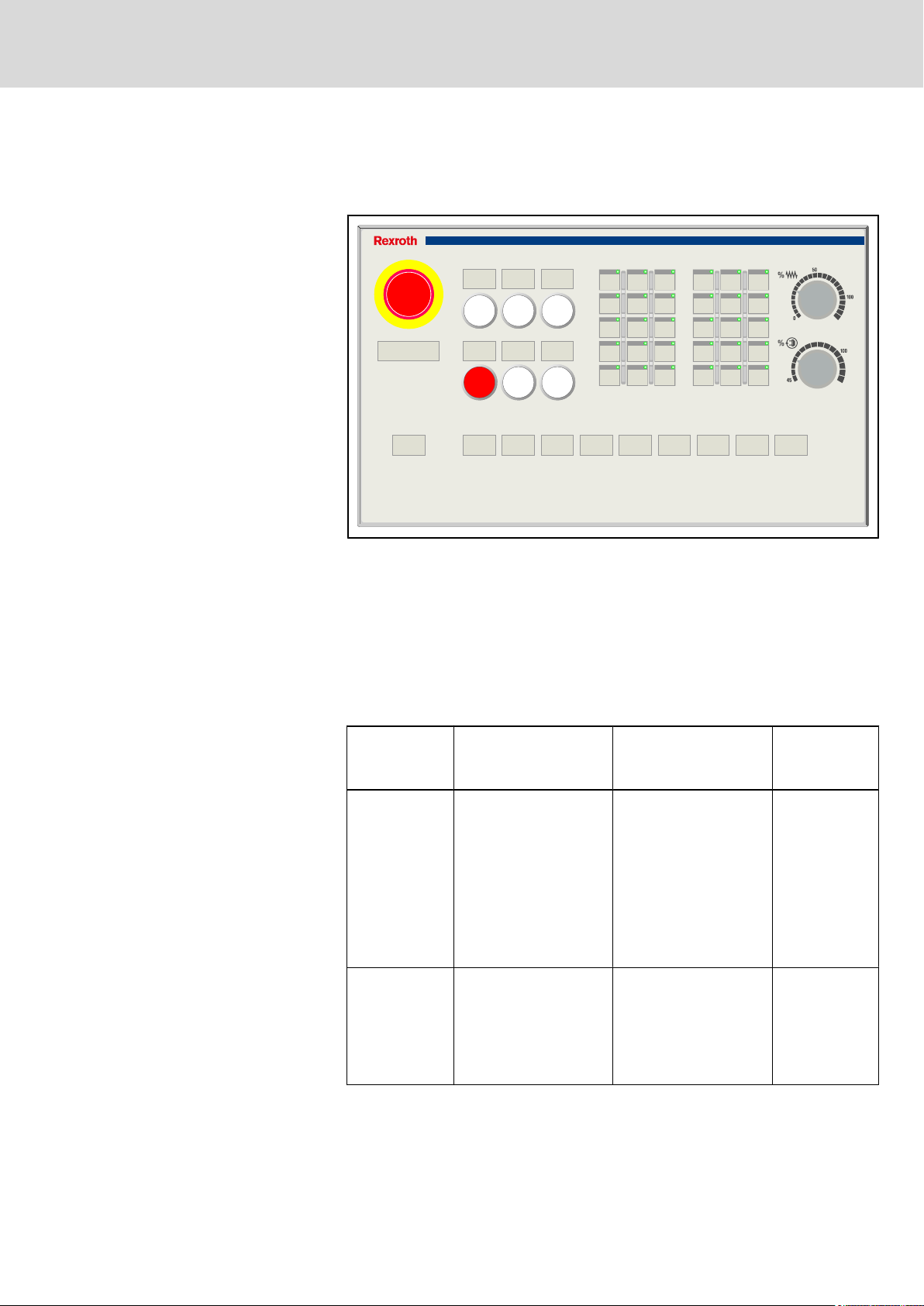
1.3.2 Front View Machine Control Panel - Customized Variant (Overview)
① EMERGENCY STOP button
1.3.3 Front View Machine Control Panel VAM 12.1, Customized Variant
② Pushbuttons
③ Keypads with keys that can be freely labeled and programmed
④ Override rotary switch for feed
⑤ Override rotary switch for spindle
⑥ Pushbuttons
⑦ VAC 30.2
⑧ Euchner EKS
Fig.1-6: Front view machine control panel (customized variant)
IndraControl V
IndraControl V
DOK-SUPPL*-VAM*XX.1***-PR02-EN-P
Rexroth IndraControl VAM 12.1/42.1 Machine Control Panels
Bosch Rexroth AG 11/93
System Presentation
Fig.1-7: Customized variant VAM12.1-PB-NF-AB-TB-VD-EK-1608-D1
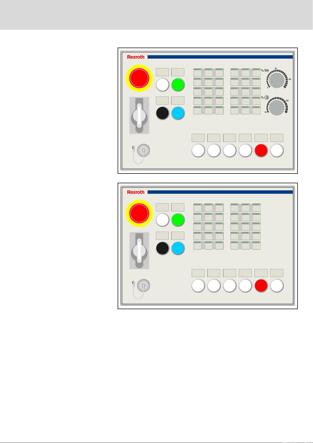
Fig.1-8: Customized variant VAM12.1-PB-NF-AB-TB-NN-EK-1608-D1
IndraControl V
IndraControl V
12/93
Bosch Rexroth AG DOK-SUPPL*-VAM*XX.1***-PR02-EN-P
Rexroth IndraControl VAM 12.1/42.1 Machine Control Panels
System Presentation
1.3.4 Front View Machine Control Panel VAM 42.1, Customized Variant
Fig.1-9: Customized variant VAM42.1-PB-NF-AB-TB-VD-EK-1608-D1
Fig.1-10: Customized variant VAM42.1-PB-NF-AB-TB-NN-EK-1608-D1
DOK-SUPPL*-VAM*XX.1***-PR02-EN-P
Rexroth IndraControl VAM 12.1/42.1 Machine Control Panels
2 Important Instructions on Use
Bosch Rexroth AG 13/93
Important Instructions on Use
2.1
Appropriate Use
2.1.1 Introduction
Rexroth products represent state-of-the-art developments and manufacturing.
They are tested prior to delivery to ensure operational safety and reliability.
WARNING
The products are designed for the use in an industrial environment and may
therefore only be used for the intended purpose. If they are not used as inten‐
ded, situations causing personal injury as well as material damage can occur.
Bosch Rexroth disclaims as manufacturer any warranty, liability or
damages
thermore, Bosch Rexroth is not paying any compensation. The user
is responsible for any risks resulting from inappropriate use of the
products.
Before using Rexroth products, the following requirements must be met to en‐
sure appropriate use of the products:
● Anyone
understand the respective safety-related guidelines as well as the instruc‐
tions on intended use.
● Hardware products have to remain in their original state, in other words,
no modification regarding the design are allowed. Software products must
not be decompiled and their source codes must not be modified.
● Damaged or faulty products must not be implemented or put into opera‐
tion.
● It must be ensured that the products are installed as specified in the doc‐
umentation.
handling one of the Rexroth products in any way has to read and
occurring due to inappropriate use of the products. Fur‐
Physical injury and material damage might re‐
sult
from an inappropriate use of the products!
2.1.2 Areas of Use and Application
machine control panels of the VAM 12.1/VAM 42.1 design by Rexroth are used
to operate control panels.
It can be necessary to connect additional sensors and actuators to control and
monitor the VAM 12.1/VAM 42.1.
NOTICE
The VAM 12.1/VAM 42.1 may exclusively be used with the accessories and
add-on components specified in this documentation. Components not named
expressly mentioned must neither be mounted nor connected. The same ap‐
plies to cables and conduits.
The products may only be operated with the expressly stated configurations
and component combinations as well as with the software and firmware which
is given and specified in the respective functional description.
Danger of destruction of the device if not ex‐
pressly
nents and other components, cables, conduits,
software and firmware is used.
stated accessories, add-on compo‐

14/93
Important Instructions on Use
Bosch Rexroth AG DOK-SUPPL*-VAM*XX.1***-PR02-EN-P
Rexroth IndraControl VAM 12.1/42.1 Machine Control Panels
Each drive control device has to be programmed before commissioning so that
the motor executes the application-specific functions.
The
VAM 12.1/VAM 42.1 were developed for the single axis as well as for the
multiple axes drive tasks and control tasks.
For the application-specific use of the VAM 12.1/VAM 42.1, device types are
available with a different drive performance and different interfaces.
For the application specific use of machine control and visualization terminals,
device types with different equipment and different interfaces are available.
Typical fields of use of the VAM 12.1/VAM 42.1 are:
● Lathes
● Milling machines
● Machining centers
The devices of the VAM 12.1/VAM 42.1 design may only be operated under the
assembly conditions and installation conditions, in the specified position of ap‐
plication and under the specified ambient conditions (temperature, degree of
protection, humidity, EMC etc.) given in this documentation.
2.2 Inappropriate Use
The application of VAM 12.1/VAM 42.1 that are not within the specified areas
of application or under operating conditions deviating from the operating con‐
ditions and technical data specified in the documentation is considered as
"inappropriate".
VAM 12.1/VAM 42.1 must not be used if ...
● it is exposed to operation conditions that do not fulfill the ambient condi‐
tions specified. For instance, operation under water, in case of extreme
variations of temperature or in extreme maximum temperatures is not al‐
lowed.
● the intended applications have not expressly been allowed by Rexroth. It
is imperative that you also note the information given in the general notes
on safety!

DOK-SUPPL*-VAM*XX.1***-PR02-EN-P
Rexroth IndraControl VAM 12.1/42.1 Machine Control Panels
Safety Instructions for Electric Drives and Controls
Bosch Rexroth AG 15/93
3 Safety Instructions for Electric Drives and Controls
3.1
Definitions of Terms
Application Documentation
Component
Control System
Device
Electrical Equipment
Electric Drive System
Installation
Machine
Manufacturer
Product
Project Planning Manual
Qualified Persons
Application documentation comprises the entire documentation used to inform
the user of the product about the use and safety-relevant features for config‐
uring, integrating, installing, mounting, commissioning, operating, maintaining,
repairing and decommissioning the product. The following terms are also used
for this kind of documentation: User Guide, Operation Manual, Commissioning
Manual, Instruction Manual, Project Planning Manual, Application Manual, etc.
A component is a combination of elements with a specified function, which are
part of a piece of equipment, device or system. Components of the electric drive
and control system are, for example, supply units, drive controllers, mains
choke, mains filter, motors, cables, etc.
A control system comprises several interconnected control components placed
on the market as a single functional unit.
A device is a finished product with a defined function, intended for users and
placed on the market as an individual piece of merchandise.
Electrical equipment encompasses all devices used to generate, convert, trans‐
mit, distribute or apply electrical energy, such as electric motors, transformers,
switching devices, cables, lines, power-consuming devices, circuit board as‐
semblies, plug-in units, control cabinets, etc.
An electric drive system comprises all components from mains supply to motor
shaft; this includes, for example, electric motor(s), motor encoder(s), supply
units and drive controllers, as well as auxiliary and additional components, such
as mains filter, mains choke and the corresponding lines and cables.
An installation consists of several devices or systems interconnected for a de‐
fined purpose and on a defined site which, however, are not intended to be
placed on the market as a single functional unit.
A machine is the entirety of interconnected parts or units at least one of which
is movable. Thus, a machine consists of the appropriate machine drive ele‐
ments, as well as control and power circuits, which have been assembled for
a specific application. A machine is, for example, intended for processing,
treatment, movement or packaging of a material. The term "machine" also cov‐
ers a combination of machines which are arranged and controlled in such a way
that they function as a unified whole.
The manufacturer is an individual or legal entity bearing responsibility for the
design and manufacture of a product which is placed on the market in the in‐
dividual's or legal entity's name. The manufacturer can use finished products,
finished parts or finished elements, or contract out work to subcontractors.
However, the manufacturer must always have overall control and possess the
required authority to take responsibility for the product.
Examples of a product: Device, component, part, system, software, firmware,
among other things.
A project planning manual is part of the application documentation used to
support the sizing and planning of systems, machines or installations.
In terms of this application documentation, qualified persons are those persons
who are familiar with the installation, mounting, commissioning and operation
of the components of the electric drive and control system, as well as with the
hazards this implies, and who possess the qualifications their work requires. To
comply with these qualifications, it is necessary, among other things,

16/93
Safety Instructions for Electric Drives and Controls
Bosch Rexroth AG DOK-SUPPL*-VAM*XX.1***-PR02-EN-P
Rexroth IndraControl VAM 12.1/42.1 Machine Control Panels
1) to be trained, instructed or authorized to switch electric circuits and devices
safely on and off, to ground them and to mark them
2) to be trained or instructed to maintain and use adequate safety equipment
3) to attend a course of instruction in first aid
User
A
user is a person installing, commissioning or using a product which has been
placed on the market.
3.2 General Information
3.2.1 Using the Safety Instructions and Passing Them on to Others
Do not attempt to install and operate the components of the electric drive and
control system without first reading all documentation provided with the product.
Read and understand these safety instructions and all user documentation prior
to working with these components. If you do not have the user documentation
for the components, contact your responsible Bosch Rexroth sales partner. Ask
for these documents to be sent immediately to the person or persons respon‐
sible for the safe operation of the components.
If the component is resold, rented and/or passed on to others in any other form,
these safety instructions must be delivered with the component in the official
language of the user's country.
Improper use of these components, failure to follow the safety instructions in
this document or tampering with the product, including disabling of safety de‐
vices, could result in property damage, injury, electric shock or even death.
3.2.2 Requirements for Safe Use
Read the following instructions before initial commissioning of the components
of the electric drive and control system in order to eliminate the risk of injury
and/or property damage. You must follow these safety instructions.
● Bosch Rexroth is not liable for damages resulting from failure to observe
the safety instructions.
● Read the operating, maintenance and safety instructions in your language
before commissioning. If you find that you cannot completely understand
the application documentation in the available language, please ask your
supplier to clarify.
● Proper and correct transport, storage, mounting and installation, as well
as care in operation and maintenance, are prerequisites for optimal and
safe operation of the component.
● Only qualified persons may work with components of the electric drive and
control system or within its proximity.
● Only use accessories and spare parts approved by Bosch Rexroth.
● Follow the safety regulations and requirements of the country in which the
components of the electric drive and control system are operated.
● Only use the components of the electric drive and control system in the
manner that is defined as appropriate. See chapter "Appropriate Use".
● The ambient and operating conditions given in the available application
documentation must be observed.
● Applications for functional safety are only allowed if clearly and explicitly
specified in the application documentation "Integrated Safety Technolo‐
gy". If this is not the case, they are excluded. Functional safety is a safety

DOK-SUPPL*-VAM*XX.1***-PR02-EN-P
Rexroth IndraControl VAM 12.1/42.1 Machine Control Panels
concept in which measures of risk reduction for personal safety depend
on electrical, electronic or programmable control systems.
● The
● Commissioning of the delivered components is only allowed once it is sure
● Operation is only allowed if the national EMC regulations for the applica‐
● The instructions for installation in accordance with EMC requirements can
● The technical data, connection and installation conditions of the compo‐
information given in the application documentation with regard to the
use of the delivered components contains only examples of applications
and suggestions.
The machine and installation manufacturers must
– make sure that the delivered components are suited for their individ‐
ual application and check the information given in this application
documentation with regard to the use of the components,
– make sure that their individual application complies with the appli‐
cable safety regulations and standards and carry out the required
measures, modifications and complements.
that the machine or installation in which the components are installed
complies with the national regulations, safety specifications and standards
of the application.
tion are met.
be found in the section on EMC in the respective application documenta‐
tion.
The machine or installation manufacturer is responsible for compliance
with the limit values as prescribed in the national regulations.
nents are specified in the respective application documentations and must
be followed at all times.
National regulations which the user must take into account
● European countries: In accordance with European EN standards
● United States of America (USA):
– National Electrical Code (NEC)
– National Electrical Manufacturers Association (NEMA), as well as
local engineering regulations
– Regulations of the National Fire Protection Association (NFPA)
● Canada: Canadian Standards Association (CSA)
● Other countries:
– International Organization for Standardization (ISO)
– International Electrotechnical Commission (IEC)
Bosch Rexroth AG 17/93
Safety Instructions for Electric Drives and Controls
3.2.3 Hazards by Improper Use
● High electrical voltage and high working current! Danger to life or serious
injury by electric shock!
● High electrical voltage by incorrect connection! Danger to life or injury by
electric shock!
● Dangerous movements! Danger to life, serious injury or property damage
by unintended motor movements!
● Health hazard for persons with heart pacemakers, metal implants and
hearing aids in proximity to electric drive systems!
● Risk of burns by hot housing surfaces!

18/93
Bosch Rexroth AG DOK-SUPPL*-VAM*XX.1***-PR02-EN-P
Safety Instructions for Electric Drives and Controls
Rexroth IndraControl VAM 12.1/42.1 Machine Control Panels
● Risk
of injury by improper handling! Injury by crushing, shearing, cutting,
hitting!
● Risk of injury by improper handling of batteries!
● Risk of injury by improper handling of pressurized lines!

DOK-SUPPL*-VAM*XX.1***-PR02-EN-P
Rexroth IndraControl VAM 12.1/42.1 Machine Control Panels
Safety Instructions for Electric Drives and Controls
Bosch Rexroth AG 19/93
3.3 Instructions with Regard to Specific Dangers
3.3.1
Protection Against Contact With Electrical Parts and Housings
This section concerns components of the electric drive and control
system with voltages of more than 50 volts.
Contact with parts conducting voltages above 50 volts can cause personal
danger
and control system, it is unavoidable that some parts of these components
conduct dangerous voltage.
High electrical voltage! Danger to life, risk of injury by electric shock or serious
injury!
● Only qualified persons are allowed to operate, maintain and/or repair the
● Follow the general installation and safety regulations when working on
● Before switching on, the equipment grounding conductor must have been
● Even for brief measurements or tests, operation is only allowed if the
● Before accessing electrical parts with voltage potentials higher than 50 V,
● With electric components, observe the following aspects:
● Install the covers and guards provided for this purpose before switching
● Never touch electrical connection points of the components while power
● Do not remove or plug in connectors when the component has been pow‐
● Under specific conditions, electric drive systems can be operated at mains
● Secure built-in devices from penetrating foreign objects and water, as well
High housing voltage and high leakage current! Danger to life, risk of injury by
electric shock!
● Before switching on and before commissioning, ground or connect the
and electric shock. When operating components of the electric drive
components of the electric drive and control system.
power installations.
permanently connected to all electric components in accordance with the
connection diagram.
equipment grounding conductor has been permanently connected to the
points of the components provided for this purpose.
you must disconnect electric components from the mains or from the pow‐
er supply unit. Secure the electric component from reconnection.
Always wait 30 minutes after switching off power to allow live capacitors
to discharge before accessing an electric component. Measure the elec‐
trical voltage of live parts before beginning to work to make sure that the
equipment is safe to touch.
on.
is turned on.
ered.
protected by residual-current-operated circuit-breakers sensitive to uni‐
versal current (RCDs/RCMs).
as from direct contact, by providing an external housing, for example a
control cabinet.
components of the electric drive and control system to the equipment
grounding conductor at the grounding points.
20/93
Bosch Rexroth AG DOK-SUPPL*-VAM*XX.1***-PR02-EN-P
Safety Instructions for Electric Drives and Controls
Rexroth IndraControl VAM 12.1/42.1 Machine Control Panels
● Connect
the equipment grounding conductor of the components of the
electric drive and control system permanently to the main power supply at
all times. The leakage current is greater than 3.5 mA.
● Establish an equipment grounding connection with a minimum cross sec‐
tion according to the table below. With an outer conductor cross section
smaller than 10 mm2 (8 AWG), the alternative connection of two equip‐
ment grounding conductors is allowed, each having the same cross
section as the outer conductors.
Cross section outer con‐
ductor
1.5 mm2 (16 AWG)
2.5 mm2 (14 AWG) 2 × 2.5 mm2 (14 AWG)
4 mm2 (12 AWG) 2 × 4 mm2 (12 AWG)
6 mm2 (10 AWG) 2 × 6 mm2 (10 AWG)
10 mm2 (8 AWG)
16 mm2 (6 AWG)
25 mm2 (4 AWG)
Minimum cross section equipment grounding conductor
Leakage current ≥ 3.5 mA
1 equipment grounding
conductor
10 mm2 (8 AWG)
16 mm2 (6 AWG)
2 equipment grounding con‐
ductors
2 × 1.5 mm2 (16 AWG)
-
-
-
35 mm2 (2 AWG)
50 mm2 (1/0 AWG) 25 mm2 (4 AWG)
70 mm2 (2/0 AWG) 35 mm2 (2 AWG)
... ... ...
Fig.3-1: Minimum Cross Section of the Equipment Grounding Connection
-
-
-
3.3.2 Protective Extra-Low Voltage as Protection Against Electric Shock
Protective extra-low voltage is used to allow connecting devices with basic in‐
sulation to extra-low voltage circuits.
On components of an electric drive and control system provided by Bosch
Rexroth, all connections and terminals with voltages between 5 and 50 volts
are PELV ("Protective Extra-Low Voltage") systems. It is allowed to connect
devices equipped with basic insulation (such as programming devices, PCs,
notebooks, display units) to these connections.
Danger to life, risk of injury by electric shock! High electrical voltage by incorrect
connection!
If extra-low voltage circuits of devices containing voltages and circuits of more
than 50 volts (e.g., the mains connection) are connected to Bosch Rexroth
products, the connected extra-low voltage circuits must comply with the re‐
quirements for PELV ("Protective Extra-Low Voltage").
3.3.3 Protection Against Dangerous Movements
Dangerous movements can be caused by faulty control of connected motors.
Some common examples are:

DOK-SUPPL*-VAM*XX.1***-PR02-EN-P
Rexroth IndraControl VAM 12.1/42.1 Machine Control Panels
● Improper or wrong wiring or cable connection
●
Operator errors
● Wrong input of parameters before commissioning
● Malfunction of sensors and encoders
● Defective components
● Software or firmware errors
These errors can occur immediately after equipment is switched on or even
after an unspecified time of trouble-free operation.
The monitoring functions in the components of the electric drive and control
system will normally be sufficient to avoid malfunction in the connected drives.
Regarding personal safety, especially the danger of injury and/or property dam‐
age, this alone cannot be relied upon to ensure complete safety. Until the
integrated monitoring functions become effective, it must be assumed in any
case that faulty drive movements will occur. The extent of faulty drive move‐
ments depends upon the type of control and the state of operation.
Dangerous movements! Danger to life, risk of injury, serious injury or property
damage!
A risk assessment must be prepared for the installation or machine, with its
specific conditions, in which the components of the electric drive and control
system are installed.
As a result of the risk assessment, the user must provide for monitoring func‐
tions and higher-level measures on the installation side for personal safety. The
safety regulations applicable to the installation or machine must be taken into
consideration. Unintended machine movements or other malfunctions are pos‐
sible if safety devices are disabled, bypassed or not activated.
To avoid accidents, injury and/or property damage:
● Keep free and clear of the machine’s range of motion and moving machine
parts. Prevent personnel from accidentally entering the machine’s range
of motion by using, for example:
– Safety fences
– Safety guards
– Protective coverings
– Light barriers
● Make sure the safety fences and protective coverings are strong enough
to resist maximum possible kinetic energy.
● Mount emergency stopping switches in the immediate reach of the oper‐
ator. Before commissioning, verify that the emergency stopping equip‐
ment works. Do not operate the machine if the emergency stopping switch
is not working.
● Prevent unintended start-up. Isolate the drive power connection by means
of OFF switches/OFF buttons or use a safe starting lockout.
● Make sure that the drives are brought to safe standstill before accessing
or entering the danger zone.
● Additionally secure vertical axes against falling or dropping after switching
off the motor power by, for example,
– mechanically securing the vertical axes,
– adding an external braking/arrester/clamping mechanism or
– ensuring sufficient counterbalancing of the vertical axes.
Bosch Rexroth AG 21/93
Safety Instructions for Electric Drives and Controls

22/93
Safety Instructions for Electric Drives and Controls
Bosch Rexroth AG DOK-SUPPL*-VAM*XX.1***-PR02-EN-P
Rexroth IndraControl VAM 12.1/42.1 Machine Control Panels
● The
● Disconnect electrical power to the components of the electric drive and
● Prevent the operation of high-frequency, remote control and radio equip‐
standard equipment motor holding brake or an external holding brake
controlled by the drive controller is not sufficient to guarantee personal
safety!
control system using the master switch and secure them from reconnec‐
tion ("lock out") for:
– Maintenance and repair work
– Cleaning of equipment
– Long periods of discontinued equipment use
ment near components of the electric drive and control system and their
supply leads. If the use of these devices cannot be avoided, check the
machine or installation, at initial commissioning of the electric drive and
control system, for possible malfunctions when operating such high-fre‐
quency, remote control and radio equipment in its possible positions of
normal use. It might possibly be necessary to perform a special electro‐
magnetic compatibility (EMC) test.
3.3.4 Protection Against Magnetic and Electromagnetic Fields During Oper‐
ation and Mounting
Magnetic and electromagnetic fields generated by current-carrying conductors
or permanent magnets of electric motors represent a serious danger to persons
with heart pacemakers, metal implants and hearing aids.
Health hazard for persons with heart pacemakers, metal implants and hearing
aids in proximity to electric components!
● Persons with heart pacemakers and metal implants are not allowed to
enter the following areas:
– Areas in which components of the electric drive and control systems
are mounted, commissioned and operated.
– Areas in which parts of motors with permanent magnets are stored,
repaired or mounted.
● If it is necessary for somebody with a heart pacemaker to enter such an
area, a doctor must be consulted prior to doing so. The noise immunity of
implanted heart pacemakers differs so greatly that no general rules can
be given.
● Those with metal implants or metal pieces, as well as with hearing aids,
must consult a doctor before they enter the areas described above.
3.3.5 Protection Against Contact With Hot Parts
Hot surfaces of components of the electric drive and control system. Risk of
burns!
● Do not touch hot surfaces of, for example, braking resistors, heat sinks,
supply units and drive controllers, motors, windings and laminated cores!
● According to the operating conditions, temperatures of the surfaces can
be higher than 60 °C (140 °F) during or after operation.
● Before touching motors after having switched them off, let them cool down
for a sufficient period of time. Cooling down can require up to 140 mi‐
nutes! The time required for cooling down is approximately five times the
thermal time constant specified in the technical data.

DOK-SUPPL*-VAM*XX.1***-PR02-EN-P
Rexroth IndraControl VAM 12.1/42.1 Machine Control Panels
Safety Instructions for Electric Drives and Controls
● After switching chokes, supply units and drive controllers off, wait 15 mi‐
nutes to allow them to cool down before touching them.
● Wear safety gloves or do not work at hot surfaces.
● For certain applications, and in accordance with the respective safety reg‐
ulations, the manufacturer of the machine or installation must take meas‐
ures to avoid injuries caused by burns in the final application. These
measures can be, for example: Warnings at the machine or installation,
guards (shieldings or barriers) or safety instructions in the application
documentation.
3.3.6 Protection During Handling and Mounting
Risk of injury by improper handling! Injury by crushing, shearing, cutting, hitting!
● Observe the relevant statutory regulations of accident prevention.
● Use suitable equipment for mounting and transport.
● Avoid jamming and crushing by appropriate measures.
● Always use suitable tools. Use special tools if specified.
● Use lifting equipment and tools in the correct manner.
● Use suitable protective equipment (hard hat, safety goggles, safety shoes,
safety gloves, for example).
● Do not stand under hanging loads.
● Immediately clean up any spilled liquids from the floor due to the risk of
falling!
Bosch Rexroth AG 23/93
3.3.7 Battery Safety
Batteries consist of active chemicals in a solid housing. Therefore, improper
handling can cause injury or property damage.
Risk of injury by improper handling!
● Do not attempt to reactivate low batteries by heating or other methods (risk
of explosion and cauterization).
● Do not attempt to recharge the batteries as this may cause leakage or
explosion.
● Do not throw batteries into open flames.
● Do not dismantle batteries.
● When replacing the battery/batteries, do not damage the electrical parts
installed in the devices.
● Only use the battery types specified for the product.
Environmental protection and disposal! The batteries contained in
the
product are considered dangerous goods during land, air, and
sea transport (risk of explosion) in the sense of the legal regulations.
Dispose of used batteries separately from other waste. Observe the
national regulations of your country.
24/93
Safety Instructions for Electric Drives and Controls
Bosch Rexroth AG DOK-SUPPL*-VAM*XX.1***-PR02-EN-P
Rexroth IndraControl VAM 12.1/42.1 Machine Control Panels
3.3.8 Protection Against Pressurized Systems
3.4
According
components cooled with liquids and compressed air can be partially supplied
with externally fed, pressurized media, such as compressed air, hydraulics oil,
cooling liquids and cooling lubricants. Improper handling of the connected sup‐
ply systems, supply lines or connections can cause injuries or property damage.
Risk of injury by improper handling of pressurized lines!
● Do not attempt to disconnect, open or cut pressurized lines (risk of explo‐
● Observe the respective manufacturer's operating instructions.
● Before dismounting lines, relieve pressure and empty medium.
● Use suitable protective equipment (safety goggles, safety shoes, safety
● Immediately clean up any spilled liquids from the floor due to the risk of
to the information given in the Project Planning Manuals, motors and
sion).
gloves, for example).
falling!
Environmental protection and disposal! The agents (e.g., fluids)
used
to operate the product might not be environmentally friendly.
Dispose of agents harmful to the environment separately from other
waste. Observe the national regulations of your country.
Explanation of Signal Words and the Safety Alert Symbol
The Safety Instructions in the available application documentation contain spe‐
cific signal words (DANGER, WARNING, CAUTION or NOTICE) and, where
required, a safety alert symbol (in accordance with ANSI Z535.6-2006).
The signal word is meant to draw the reader's attention to the safety instruction
and identifies the hazard severity.
The safety alert symbol (a triangle with an exclamation point), which precedes
the signal words DANGER, WARNING and CAUTION, is used to alert the
reader to personal injury hazards.
DANGER
In case of non-compliance with this safety instruction, death or serious injury
will occur.
WARNING
In case of non-compliance with this safety instruction, death or serious injury
could occur.
CAUTION
In case of non-compliance with this safety instruction, minor or moderate injury
could occur.

DOK-SUPPL*-VAM*XX.1***-PR02-EN-P
Rexroth IndraControl VAM 12.1/42.1 Machine Control Panels
Bosch Rexroth AG 25/93
Safety Instructions for Electric Drives and Controls
NOTICE
In case of non-compliance with this safety instruction, property damage could
occur.

26/93
Bosch Rexroth AG DOK-SUPPL*-VAM*XX.1***-PR02-EN-P
Rexroth IndraControl VAM 12.1/42.1 Machine Control Panels
DOK-SUPPL*-VAM*XX.1***-PR02-EN-P
Rexroth IndraControl VAM 12.1/42.1 Machine Control Panels
4 Technical Data
Bosch Rexroth AG 27/93
Technical Data
4.1
Basic Device
Degree of protection Front panel IP 54 according to EN 60 529, IEC 529
Degree of protection 1 according to DIN EN 50178
Color of the front foil RAL 7035 light gray
Dimensions (W × H × D) 350 mm × 240 mm x 58 mm
Mounting cut-out (W
× H)
Mounting depth 102 mm
Weight Approx. 1.8 kg Approx. 2 kg
Material of the front pan‐elaluminium, colorless anodized; polyester foil with embossed
VAM 12.1 VAM 42.1
407 mm × 240 mm x 58 mm
350 mm × 240 mm x 70 mm
for customized variant
324 mm × 215 mm 380 mm × 215 mm
(with PROFIBUS DP connector)
keys
407 mm × 240 mm x 70 mm
for customized variant
Fig.4-1: General technical data
VAM 12.1 VAM 42.1
Voltage supply Electrically isolated
Logic supply U
Current consumption
from U
L
Input and output supply
U
Q
Current consumption
from U
Q
Fuse SMD fuse 3 A
Reverse voltage protec‐
tion
L
DC 24 V (19.2 ... 30 V), PELV
Standard devices: Max. 0.2 A
Customized devices with VAC 30.2: Max. 1.7 A
DC 24 V (19.2 ... 30 V), PELV
Max. 1.7 A
Integrated
Fig.4-2: Electrical data
NOTICE
Destruction of the filter choke in the input area
caused by continuous operation outside the
range of 19.2 V to 30 V.
Operate the device only within the permissible range between 19.2 V to 30 V.
D-SUB female connector strips, 25-pin, 9-pin
Male connector strips by Weidmüller, 4-pin, 6-pin and 8-pin
Fig.4-3: Connection method
 Loading...