

Bosch Rexroth IndraControl Operating Instructions Manual
The Drive & Control Company
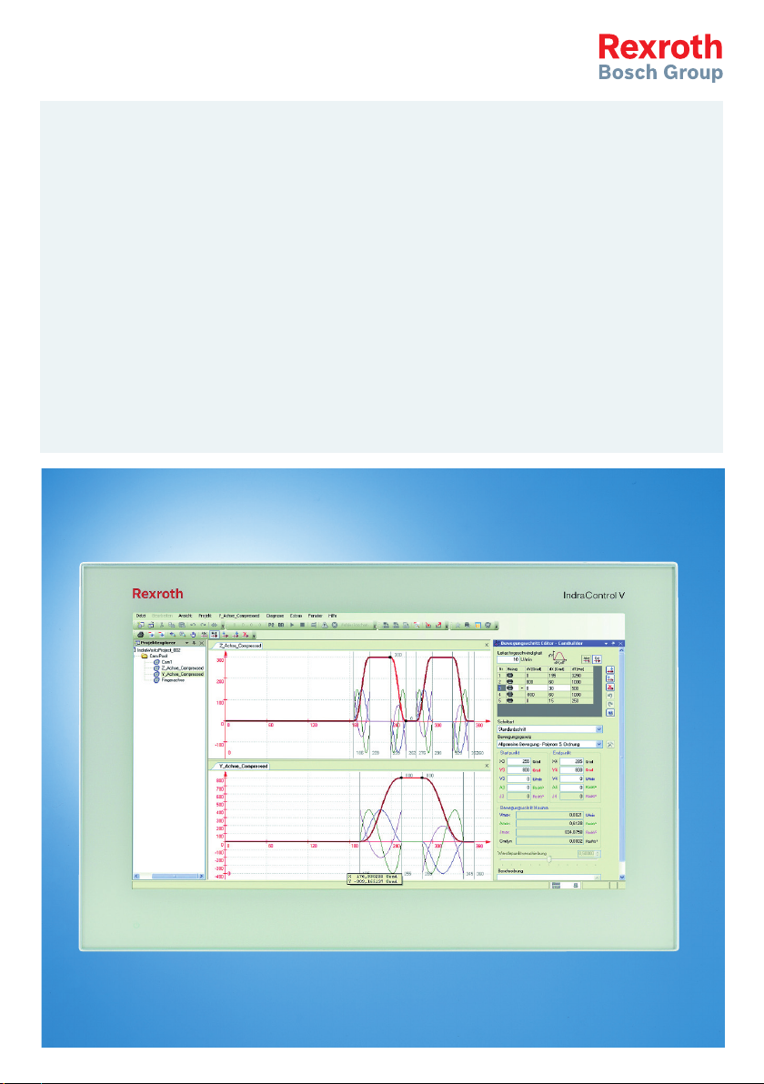
Rexroth IndraControl
VEP 07.6/15.6 Multi Touch
Operator Display– Housing Devices and Built-In Devices
Operating Instructions
R911342321
Edition 01

Bosch Rexroth AG VEP 07.6/15.6 Multi Touch
Change Record
Edition
Release
Notes
Date
Edition 01 2015-06 First edition
Copyright
© Bosch Rexroth AG 2015
This document, as well as the data, specifications and other information set
forth in it, are the exclusive property of Bosch Rexroth AG. It may not be reproduced or given to third parties without its consent.
Liability
The specified data is intended for product description purposes only and shall
not be deemed to be a guaranteed characteristic unless expressly stipulated in
the contract. All rights are reserved with respect to the content of this documentation and the availability of the product.
Published by
Development automation systems control hardware HP (KW/MePe)
RS-54e69e42616845aa0a6846a501590f06-1-en-US-6

VEP 07.6/15.6 Multi Touch Bosch Rexroth AG
Table of Contents
Table of Contents
Page
1 About this documentation..................................................................... 1
2 Product identification and scope of delivery......................................... 2
2.1 Product identification............................................................................ 2
2.2 Scope of delivery................................................................................... 3
3 Using safety instructions........................................................................ 3
3.1 Safety instructions – Structure.............................................................. 3
3.2 Explaining signal words and safety alert symbol................................... 4
3.3 Symbols Used........................................................................................ 5
4 Intended use.......................................................................................... 5
5 Spare parts, accessories and wear parts.............................................. 6
5.1 External 24 V power supply unit............................................................ 6
5.2 Lithium battery...................................................................................... 6
5.3 CFAST card............................................................................................ 6
5.4 Rubber grommet for cable bushing....................................................... 6
5.5 Wear parts............................................................................................. 6
6 Ambient conditions................................................................................ 7
7 Technical data........................................................................................ 8
7.1 General technical data........................................................................... 8
7.2 Optical characteristic values.................................................................. 8
7.2.1 TFT......................................................................................................... 8
7.2.2 Input system (multi-touch front)............................................................ 9
7.3 E-STOP button....................................................................................... 9
8 Standards.............................................................................................. 9
8.1 Standards used...................................................................................... 9
8.2 CE marking........................................................................................... 10
8.2.1 Declaration of conformity.................................................................... 10
8.3 UL/CSA certified.................................................................................. 11
9 Interfaces............................................................................................. 11
9.1 View..................................................................................................... 11
DOK-SUPPL*-VEPXX.6MTHU-IT01-EN-P
I

Bosch Rexroth AG
VEP 07.6/15.6 Multi Touch
Table of Contents
Page
9.2 Overview.............................................................................................. 13
9.3 24 V DC voltage supply........................................................................ 13
9.4 Battery connection.............................................................................. 14
9.5 USB interfaces..................................................................................... 14
9.6 Ethernet interfaces.............................................................................. 16
9.7 Keypad................................................................................................. 17
9.7.1 View..................................................................................................... 17
9.7.2 Connections ........................................................................................ 18
9.7.3 Keypad connection scheme................................................................. 19
9.7.4 Pin assignment of the keypad.............................................................. 19
10 Mounting, demounting and electric installation.................................. 21
10.1 Housing dimensions............................................................................. 21
10.2 Mounting notes for built-in devices..................................................... 24
10.3 Mounting the built-in devices............................................................... 24
10.4 Mounting dimensions of the built-in devices....................................... 27
10.5 Demounting the built-in devices.......................................................... 27
10.6 Mounting the VEP 15.6 housing devices.............................................. 28
10.6.1 Mounting notes.................................................................................... 28
10.6.2 Attachment to standardized VESA bracket.......................................... 29
10.6.3 Dimensions of the VEP 15.6 housing devices (rear side).................... 32
10.7 Electric connection.............................................................................. 32
10.7.1 General information............................................................................. 32
11 Commissioning.................................................................................... 35
12 Device description............................................................................... 35
12.1 General information............................................................................. 35
12.2 Housing devices................................................................................... 36
12.3 Built-in devices..................................................................................... 37
12.4 Operating display................................................................................. 37
13 Error causes and troubleshooting........................................................ 38
14 Maintenance........................................................................................ 38
14.1 General information............................................................................. 38
14.2 Display................................................................................................. 38
14.3 Cleaning notes..................................................................................... 39
14.4 Regular maintenance tasks.................................................................. 39
II
DOK-SUPPL*-VEPXX.6MTHU-IT01-EN-P

VEP 07.6/15.6 Multi Touch Bosch Rexroth AG
Table of Contents
Page
14.5 CMOS battery...................................................................................... 39
15 Ordering information........................................................................... 40
15.1 Accessories and spare parts................................................................ 40
15.2 Type code............................................................................................. 41
16 Disposal............................................................................................... 42
16.1 General information............................................................................. 42
16.2 Return.................................................................................................. 42
16.3 Packaging............................................................................................. 42
16.4 Batteries and Accumulators................................................................. 42
17 Service and support............................................................................ 42
Index.................................................................................................... 45
DOK-SUPPL*-VEPXX.6MTHU-IT01-EN-P
III

Bosch Rexroth AG VEP 07.6/15.6 Multi Touch
IV
DOK-SUPPL*-VEPXX.6MTHU-IT01-EN-P
Presales Aftersales
Selection
Mounting
(assembly/installation)
Engineering
Commissioning
Operation
Decommissioning
Product
phases
Target
groups
Activities
Design engineer
Programmer
Technologist
Process
specialist
Select
Prepare
Design
Construct
Mechanic/
electrician
Unpack
Mount
Install
Programmer
Commissioning engineer
Parameterize
Program
Configure
Simulate
Technologist
Process specialist
Optimize
Test
Machine
operator
Maintenance
technician
Service
Operate
Maintain
Remove
faults
Create
the NC program
Mechanic/
electrician
Disposal company
Dismount
Dispose
VEP 07.6/15.6 Multi Touch
Bosch Rexroth AG
About this documentation
1 About this documentation
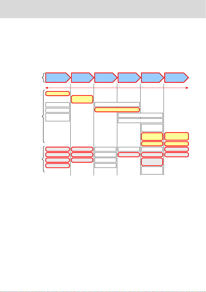
Overview on target groups and product phases
In the following illustration, the framed activities, product phases and target
groups refer to the present documentation.
Example: In the product phase "Mounting (assembly/installation)", the "mechanic/electrician" can execute the activity "install" using this documentation.
Fig. 1-1: Assigning the present documentation to the target groups, product phases and activities of the target group
Purpose
This document instructs the technical staff of the machine manufacturer on how
to perform the mechanical and electrical installation safely and on how to commission the device.
Required qualifications: Individual who is able to assess the tasks assigned and
identify possible safety risks owing to qualification in the subject, knowledge
and experience. The individual should also be familiar with the standards and
regulations.
Availability
This document is part of the present product delivery. This document has to be
available at any time. The product has to be passed on only together with this
document.
DOK-SUPPL*-VEPXX.6MTHU-IT01-EN-P
1/49

Bosch Rexroth AG
Product identification and scope of delivery
Scope
This operating instruction applies to all multi-touch operator displays whose
type code starts either with "VEP15.6…" or "VEP 07.6".
The type code specifications are located on the type plate of the device, refer to
chapter 2.1 "Product identification" on page 2.
Related documents
Title Part number and document type
Rexroth IndraControl
VAP 01
Power Supply Unit
Rexroth IndraControl
VAU 01.1
UPS with Communication Interface
Rexroth IndraControl
V-Devices
Operating Systems
Tab. 1-1: Related documentation
Customer Feedback
Customer requests, comments or suggestions for improvement are of great importance to us. Please email your feedback on the documentations to Feed-
back.Documentation@boschrexroth.de. Directly insert comments in the elec-
tronic PDF document and send the PDF file to Bosch Rexroth.
R911339613
Operating Instructions
R911336867
Operating Instructions
R911343901
Project Planning Manual
VEP 07.6/15.6 Multi Touch
2
Product identification and scope of delivery
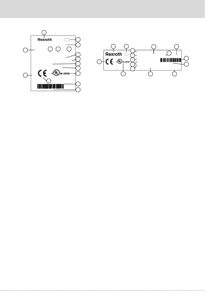
2.1 Product identification
The type plate is located on the rear side or at the side of the device.
2/49
DOK-SUPPL*-VEPXX.6MTHU-IT01-EN-P
13026
2
3
6
7
7
10
11
12
13
14
9
8
5
4
1
Bosch rexroth Electric Drives and Controls GmbH
D-64711 Erbach Made in Germany
BTV40.1AHB-256S-P5CUN-FW
UN IN 3AC 230V 50760Hz
IN
OUT 10/7,5/5/5/1,5/1,5A max.
I-C-B-T-V
SW-Version V0,002
MNR: 1070170021 -101 03W19
7261
IND.CONT.EQ 17YB
SN: 123456814
15
16
Made in Germany
UN: AC 230V / 115V
IN: 0,7A / 1,4A
MNR: 1070086255 -101
V-Nr: 1
TYP: PCPNL PEN400J1287 IS110-T
Bosch Rexroth Electric Drives and Controls GmbH
D-6471
1 Erbach
SN: 004012652
7261
IND.CONT-EQ 17YB
XXXXXXXXXXXXXXXXX
I-C-B-H-T-V
FD: 05W01
1
2
3
4
8
9
5
10
6
12
11
13
14
15
16
VEP 07.6/15.6 Multi Touch
Bosch Rexroth AG
Using safety instructions
1 Logotype
2 Division or plant number
3 Type designation code (type code)
4 Parts number
5 State of revision
6 Date of manufacture (yyWww)
7 Nominal voltage
8 Nominal current
Fig. 2-1: Exemplary type plates
2.2 Scope of delivery
● Operator display
● Safety instructions
● Mounting kit and cables
● 24 V female connector strip
3
Using safety instructions
3.1 Safety instructions – Structure
The safety instructions are structured as follows:
DOK-SUPPL*-VEPXX.6MTHU-IT01-EN-P
9 Test marking
10 Version number
11 CE mark
12 Underwriters Laboratories Inc. mark
13 Serial number as barcode
14 Serial number
15 Designation of origin
16 Company address
3/49
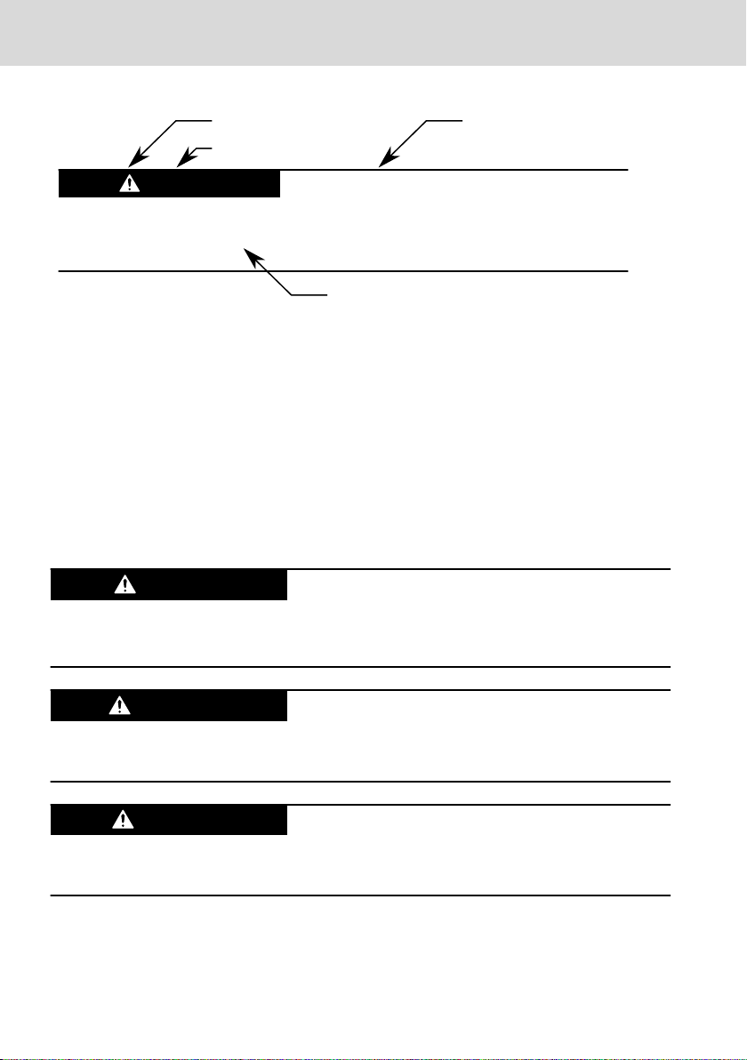
Burns and chemical burns due to wrong
battery treatment!
CAUTION
Safety alert symbol
Signal word
Consequences and
source of danger
Avoiding danger
Do not open the batteries and do not heat them over 80 °C.
DANGER
WARNING
CAUTION
Bosch Rexroth AG
Using safety instructions
Fig. 3-1: Safety instructions – structure
VEP 07.6/15.6 Multi Touch
3.2 Explaining signal words and safety alert symbol
The safety instructions in this documentation contain specific signal words (danger, warning, caution, notice) and, if necessary, a safety alert symbol (according
to ANSI Z535.6-2006).
The signal word is used to draw attention to the safety instruction and also provides information on the severity of the hazard.
The safety alert symbol (a triangle with an exclamation point), which precedes
the signal words danger,warning and caution is used to alert the reader to personal injury hazards.
In the event of non-compliance with this safety instruction, death or serious injury will occur.
In the event of non-compliance with this safety instruction, death or serious injury will occur.
In the event of non-compliance with this safety instruction, minor or moderate
injury can occur.
4/49
DOK-SUPPL*-VEPXX.6MTHU-IT01-EN-P
NOTICE
NOTICE
VEP 07.6/15.6 Multi Touch
Bosch Rexroth AG
Intended use
In the event of non-compliance with this safety instruction, material damage can
occur.
3.3 Symbols Used
Pointers are displayed as follows:
This is a note.
Tips are displayed as follows:
This is a tip.
4 Intended use
The Bosch Rexroth IndraControl VEP 07.6/VEP 15.6 operator displays are passive operator and visualization terminals. They form a PC-based operator terminal when used with a Bosch Rexroth control cabinet PC.
Risk of damaging the device if not expressly stated accessories, mounting parts and other components, cables, lines and software and firmware are used.
The operator displays may only be used as intended and with the accessories,
mounting parts and other components specified in this documentation. Components that are not expressly mentioned must neither be attached nor connected.
The same applies to cables and lines.
Only to be operated with the component configurations and combinations expressly defined and with the software and firmware specified in the corresponding functional description.
Typical areas of application of the operator display:
● Handling and assembly systems
● Packaging and food processing machines
● Printing and paper converting machines
● Machine tools
● Wood processing machines
DOK-SUPPL*-VEPXX.6MTHU-IT01-EN-P
5/49

NOTICE
Bosch Rexroth AG
Spare parts, accessories and wear parts
The operator displays may only be operated under the mounting and installation
conditions, the position and the ambient conditions (temperature, degree of
protection, humidity, EMC etc.) specified in this documentation.
Danger of destruction of the touch screen if operated with inappropriate objects.
Operate the touch screen only with your finger or with a touch pen.
VEP 07.6/15.6 Multi Touch
5 Spare parts, accessories and wear parts
5.1 External 24 V power supply unit
Ordering code Part number Description
VAP01.1H-W23-024-010-NN R911171065 External 24 V power supply unit for
Tab. 5-1: External 24 V power supply unit for the operator display
5.2 Lithium battery
Ordering code Part number Description
Battery CR2032-LD R913044871 3 V lithium battery element with connecting
IndraControl V devices
cable
Tab. 5-2: 3 V lithium battery
5.3 CFAST card
Ordering code Part number Description
CFM02.1-16G0-E-LBA-NN-NW R911173985 CFAST card 16 GB
Tab. 5-3: CFAST card
5.4 Rubber grommet for cable bushing
Rubber grommet for cable bushings for the housing device
Ordering code
DICHTEINSATZ KABEL PCT 1070925708 Rubber grommet for cable bushing
Tab. 5-4: Rubber grommet
Part number Description
5.5 Wear parts
Wear parts are not subject to any warranty.
6/49
DOK-SUPPL*-VEPXX.6MTHU-IT01-EN-P

VEP 07.6/15.6 Multi Touch
Bosch Rexroth AG
Ambient conditions
Backlight
The service life of the backlight is limited. After this period, the backlight will
produce only 50 % of its original brightness. The service life of the VEP 15.6 is
approx. 50,000 hours and of the VEP 07.6 approx. 30,000 hours if the ambient
temperature is 25 °C.
6 Ambient conditions
In operation Transport Storage
Max. ambient tempera-
ture
Max. temperature gradi-
ent
Humidity Min. relative humidity:
Air pressure Up to 3,000 m above
Mechanical strength Max. vibration:
Contamination level 2 2 2
Overvoltage category 2 - -
+0 °C to +50 °C -20 °C to +60 °C -20 °C to +60 °C
Temporal temperature
changes up to 3 K per
minute
5 %
Max. relative humidity:
85 %
Min. absolute humidity:
3
1 g/m
Max. absolute humidity:
3
25 g/m
Condensation not al-
lowed
Corresponds to climatic
class 3K3 acc. to EN
60721-3-3
sea level acc. to EN
61131-2
Frequency range:
10 … 150 Hz
Excursion: 0.75 mm at
10 … 57 Hz
Temporal temperature
changes up to 3 K per
minute
Min. relative humidity:
5 %
Max. relative humidity:
75 %
Min. absolute humidity:
3
1 g/m
Max. absolute humidity:
3
25 g/m
Condensation not al-
lowed
Corresponds to climatic
class 2K2 acc. to EN
60721-3-2
Up to 3,000 m above
sea level acc. to EN
61131-2
Max. shock:
15 g 11 ms
Acc. to EN 60068-2-27,
No malfunction
Temporal temperature
changes up to 3 K per
minute
Min. relative humidity:
5 %
Max. relative humidity:
85 %
Min. absolute humidity:
3
1 g/m
Max. absolute humidity:
3
25 g/m
Condensation not al-
lowed
Corresponds to climatic
class 1K2 acc. to EN
60721-3-1
Up to 3,000 m above
sea level acc. to EN
61131-2
Max. shock:
15 g 11 ms
Acc. to EN 60068-2-27,
No malfunction
Acceleration: 1 g at
57 ... 150 Hz
Acc. to EN 600068-2-6
Tab. 6-1: Ambient conditions
DOK-SUPPL*-VEPXX.6MTHU-IT01-EN-P
7/49

Bosch Rexroth AG
Technical data
The ambient air must not contain acids, alkaline solutions, corrosive
agents, salts, metal vapors and other electrically conductive contaminants in high concentrations.
The ambient air must be free of dust. Housing and installation compartments must at least comply with the degree of protection IP 54
acc. to DIN VDE 0470-1.
Not resistant to gas jeopardizing the function [sulphur dioxide
(SO2), hydrogen sulphide (H2S)].
VEP 07.6/15.6 Multi Touch
7 Technical data
7.1 General technical data
VEP 15.6 VEP 07.6
Display 396 mm TFT (15")
1366 × 768 pixels
16.7 million colors
Operation Multi touch
Surface of the front panel Thermally tempered glass
Degree of protection Front panel IP 65 acc. to DIN EN 60 529
Front type 1 acc. to NEMA (UL)
Built-in device Rear side IP 20
Housing device: IP65
Voltage supply 24 V DC (use a 24 V power supply unit acc. to DIN EN 60742, classification
VDE 0551, for example the VAP01.1H-W23-024-010-NN, part number
R911171065)
Current consumption 1.5 A for 24 V DC 1.1 A for 24 V DC
Power loss 36 W 26 W
USB USB 2.0 max. 500 mA/connection, USB 3.0 max. 0.9 A
Weight Housing devices: approx. 5.54 kg
Housing devices: approx. 7.04 kg
177.8 mm TFT (7")
800 x 480 pixels
262k colors
Approx. 1.82 kg
Tab. 7-1: Technical data of the VEP 15.6 and VEP 07.6
7.2 Optical characteristic values
7.2.1 TFT
The maximum permissible number and type of pixel errors of TFT displays depends on the manufacturer and is defined by the respective "incoming inspec-
8/49
DOK-SUPPL*-VEPXX.6MTHU-IT01-EN-P

VEP 07.6/15.6 Multi Touch Bosch Rexroth AG
Standards
tion" of the vendor. This "incoming inspection" is provided by the Bosch Rexroth
service if required.
The maximum brightness and color characteristics of TFT displays depends on
the manufacturer and is defined by the respective specification of the vendor.
7.2.2 Input system (multi-touch front)
The maximum permissible number and type of defects on the front or the glass,
such as trapped dust, scratches, etc. is defined in the FT
devices meet the quality guideline.
1)
. The VEP multi-touch
7.3 E-STOP button
Vendor RAFI
Switch type
Contacts
B10 value
Service life at 10 mA/24V DC
Tab. 7-2: E-STOP button data
RAFIX 22 FS+, ordering no. 130.273.301/2200
Reset by rotation
Protection type at front IP65 (DIN EN 60529)
2 × N/C contacts
1.300.000
1.000.000
8 Standards
8.1 Standards used
Standard Meaning
EN 60 204-1 Safety of machinery - Electrical equipment of machines
EN 61 000-6-4 Generic standards - Emission standard (industrial environments)
EN 61 000-6-2 Generic standards – Noise immunity (industrial environments)
EN 61 558-2-6 Transformer for 24 V power supply unit, safe separation
EN 60 664-1 Overvoltage category II
EN 61 131-2 24 V output requirements
EN 61 131-2 24 V current supply requirements
EN 60 529 Degrees of protection (including housings and installation com-
EN 60 068-2-6 Vibration test
1)
Quality standard (version December 2013) of the Fachgemeinschaft Eingabesysteme (German
association for input systems).
DOK-SUPPL*-VEPXX.6MTHU-IT01-EN-P
partments)
9/49

Bosch Rexroth AG
VEP 07.6/15.6 Multi Touch
Standards
Standard Meaning
EN 60 068-2-27 Shock test
EN 60 721-3-1 and
Climatic class
EN 60 721-3-3
Tab. 8-1: Standards used
E-STOP button - Standards
The E-STOP button is identified as safety component according to machinery directive 2006/42/EC (annex V-10, E-STOP devices) by the vendor. The compliance
with the directive is proven by adherence to the following European standards:
● IEC 60204-1 (Safety of machinery - Electrical equipment of machines)
● IEC 60947-5-1/5 (Requirements for control circuit devices, requirements for
E-STOP devices)
● ISO 13850 (Safety of machinery - E-STOP - Principles for design)
Technical data and B10d value of the E-STOP button are specified in chapter 7.3
"E-STOP button" on page 9.
8.2 CE marking
8.2.1 Declaration of conformity
The electronic products described in the present operating instructions comply
with the requirements and the target of the following EU directive and with the
following harmonized European standards:
EMC directive 2004/108/EC
The electronic products described in the present operating instructions are in-
tended for use in industrial environments and comply with the following requirements:
Standard
DIN EN 61000-6-4
(VDE 0839-6-4)
Title Edition
Electromagnetic compatibility (EMC)
September 2007
Part 6-4: Generic standards – Emission standard for indus-
trial environments (IEC 61000-6-4:2006)
DIN EN 61000-6-2
(VDE 0839-6-2)
Electromagnetic compatibility (EMC)
Part 6-2: Generic standards – Noise immunity for industrial
March 2006
environments (IEC 61000-6-2:2005)
Tab. 8-2: Standards for electromagnetic compatibility (EMC)
10/49
DOK-SUPPL*-VEPXX.6MTHU-IT01-EN-P
1
2
3
4
5
6
7
8
VEP 07.6/15.6 Multi Touch Bosch Rexroth AG
Interfaces
Loss of CE conformity due to modifications at the device.
CE marking applies only to the device upon delivery. After modifying
the device, verify CE conformity.
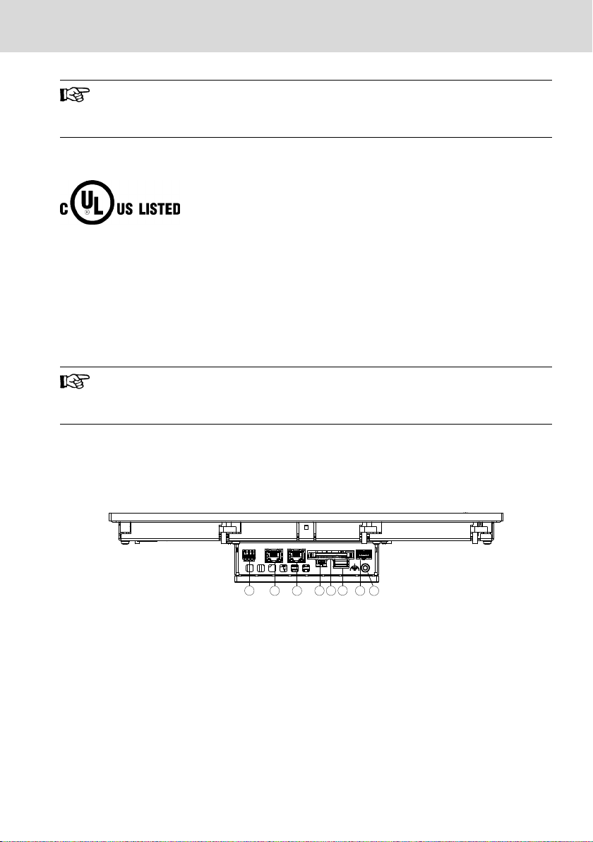
8.3 UL/CSA certified
The devices are certified according to
UL508 (Industrial Control Equipment) and
●
● C22.2 No. 142-M1987 (CSA)
UL file no. E210730
However, there can be combinations or extension stages with a limited or miss-
ing certification. Thus, verify the registration according to the UL marking on the
device.
Loss of UL/CSA conformity due to modifications at the device.
UL and CSA marking applies only to the device upon delivery. After
modifying the device, verify UL and CSA conformity.
9 Interfaces
9.1 View
Fig. 9-1: Interfaces of the built-in devices (for names, refer to the following table)
DOK-SUPPL*-VEPXX.6MTHU-IT01-EN-P
11/49
 Loading...