

Bosch Rexroth BTV 16, Rexroth BTV 40 Project Planning Manual
Industrial
Hydraulics
Electric Drives
and Controls
Linear Motion and
Assembly Technologies Pneumatics
Rexroth BTV 16 and
Rexroth BTV 40
Project Planning Manual
Service
Automation
Mobile
Hydraulics
R911293569
Edition 02
About this Documentation BTV 16/40
Title
Type of Documentation
Document Typecode
Internal File Reference
Purpose of Documentation
Record of Revisions
Rexroth BTV 16 and
Rexroth BTV 40
Project Planning Manual
DOK-SUPPL*-BTV16/40***-PR02-EN-P
Document Number, 120-2100-B341-02/EN
This documentation describes the dif ferent variants of the IndraView P16
(BTV 16.1) and IndraView P40 (BTV 40.1).
Description Release
Notes
Date
120-2100-B341-02/EN 12/03 First English Edit i on
Copyright
Validity
Published by
Note
2003 Bosch Rexroth AG
Copying this document, giving it to others and the use or com munication
of the contents thereof without express authority, are forbidden. Offenders
are liable for the payment of damages. All rights are reserved in the event
of the grant of a patent or the registration of a utility model or design
(DIN 34-1).
The specified data is for product description purpos es only and may not
be deemed to be guaranteed unless expres sly confirmed in the contract.
All rights are reserved with respect to the content of this docum entation
and the availability of the product.
Bosch Rexroth AG
Bgm.-Dr.-Nebel-Str. 2 • D-97816 Lohr a. Main
Telephone +49 (0)93 52/40-0 • Tx 68 94 21 • Fax +49 (0)93 52/40-48 85
http://www.boschrexroth.com/
Dept. BRC/EPY (NH)
This document has been printed on chlorine-free bleached paper.
DOK-SUPPL*-BTV16/40***-PR02-EN-P

BTV 16/40 Contents I
Contents
1 System Presentation 1-1
1.1 Brief Description IndraView P16 and IndraView P40....................................................................1-1
1.2 Variants.........................................................................................................................................1-1
Distinguishing Features ...........................................................................................................1-1
Operator Terminals with Keypad .............................................................................................1-2
Operator Terminals with Touch Screen...................................................................................1-2
Variants IndraView P16 (BTV 16.1).........................................................................................1-2
Variants IndraView P40 (BTV 40.1).........................................................................................1-4
1.3 Operating System .........................................................................................................................1-5
1.4 Commissioning .............................................................................................................................. 1-5
2 Important Directions for Use 2-1
2.1 Appropriate Use ............................................................................................................................2-1
Introduction ..............................................................................................................................2-1
Areas of Use and Application...................................................................................................2-2
2.2 Inappropriate Use.......................................................................................................................... 2-2
3 Safety Instructions for Electric Drives and Controls 3-1
3.1 Introduction ...................................................................................................................................3-1
3.2 Explanations.................................................................................................................................. 3-1
3.3 Hazards by Improper Use .............................................................................................................3-2
3.4 General Information ......................................................................................................................3-3
3.5 Protection Against Contact with Electrical Parts...........................................................................3-4
3.6 Protection Against Electric Shock by Protective Low Voltage (PELV) .........................................3-5
3.7 Protection Against Dangerous Movements ..................................................................................3-6
3.8 Protection Against Magnetic and Electromagnetic Fields During Operation and
Mounting .......................................................................................................................................3-7
3.9 Protection Against Contact with Hot Parts....................................................................................3-8
3.10 Protection During Handling and Mounting ....................................................................................3-8
3.11 Battery Safety................................................................................................................................ 3-9
3.12 Protection Against Pressurized Systems......................................................................................3-9
4 Technical Data 4-1
4.1 Front Panel....................................................................................................................................4-1
4.2 PC Box..........................................................................................................................................4-2
4.3 Power Supply Unit 115 V / 230 V..................................................................................................4-3
4.4 Technical Data of the Power Supply Unit 24 V.............................................................................4-3
4.5 Ambient Conditions.......................................................................................................................4-4
4.6 Compatibility Test..........................................................................................................................4-4
DOK-SUPPL*-BTV16/40***-PR02-EN-P

II Contents BTV 16/40
4.7 Used Standards ............................................................................................................................4-5
4.8 Wear Parts .................................................................................................................................... 4-5
5 Dimensions 5-1
5.1 Housing Dimensions .....................................................................................................................5-1
Housing Dimensions of the IndraView P16 .............................................................................5-1
Housing Dimensions of the IndraView P40 .............................................................................5-6
5.2 Installation...................................................................................................................................5-11
Installation Notes ...................................................................................................................5-11
Mounting Cut-Out...................................................................................................................5-11
Mounting Dimensions of the IndraView P16.......................................................................... 5-12
Mounting Dimensions of the IndraView P40.......................................................................... 5-12
6 Display and Operating Components 6-1
6.1 Backlight Switch-Off......................................................................................................................6-1
6.2 Operating and Error Indication......................................................................................................6-2
6.3 Keypad..........................................................................................................................................6-3
System Preconditions ..............................................................................................................6-3
Position of the Keys.................................................................................................................6-3
M-Keys.....................................................................................................................................6-4
6.4 Touch Screen................................................................................................................................6-4
7 PC Box 7-1
7.1 View on the Connector Panel without Special Interfaces.............................................................7-1
7.2 View on the Connector Panel with PROFIBUS DP Slave and 24 V Outputs ...............................7-1
7.3 View on the Connector Panel with SIS Interface and Operator Terminal Bus .............................7-2
7.4 Interfaces ......................................................................................................................................7-2
Overview..................................................................................................................................7-3
Serial Interface COM1 to COM3..............................................................................................7-4
Serial Multi-Mode Interface According to Rexroth Standard "SIS"..........................................7-5
IBS: BT Bus Interface ..............................................................................................................7-5
Settings of the Serial Interfaces...............................................................................................7-6
Parallel Interface LPT1 ............................................................................................................ 7-7
USB Interfaces.........................................................................................................................7-8
Ethernet Interface ....................................................................................................................7-9
VGA Interface ..........................................................................................................................7-9
Combined Keyboard/Mouse Interf ac e ...................................................................................7-11
Mouse Interface .....................................................................................................................7-11
24 V Outputs..........................................................................................................................7-12
Relay Contact "Ready" ..........................................................................................................7-13
PC Power Supply...................................................................................................................7-13
Floppy Disk Connection.........................................................................................................7-18
Battery Connection ................................................................................................................7-19
DOK-SUPPL*-BTV16/40***-PR02-EN-P

BTV 16/40 Contents III
8 Maintenance and Installation 8-1
8.1 General Information ......................................................................................................................8-1
8.2 Hard Disk ......................................................................................................................................8-2
8.3 LCD Display .................................................................................................................................. 8-3
8.4 Rechargeable Battery Pack ..........................................................................................................8-4
Installing an Extension Card....................................................................................................8-6
BIOS Settings ..........................................................................................................................8-8
9Software 9-1
9.1 Application Software of the Monitoring Function ..........................................................................9-1
Temperature Monitoring...........................................................................................................9-1
Uninterruptible Power Supply (UPS) .......................................................................................9-2
UPS Program...........................................................................................................................9-3
Functionality.............................................................................................................................9-3
Operation and Configuration of UPS NT .................................................................................9-4
9.2 Touch Screen Software............................................................................................................... 9-13
10 Ordering Information 10-1
10.1 Type Code................................................................................................................................... 10-1
BTV 16.1................................................................................................................................10-1
BTV 40.1................................................................................................................................10-3
10.2 Accessories................................................................................................................................. 10-5
Connectors and Ready-Made Cables....................................................................................10-5
Storage Media........................................................................................................................10-5
11 List of Figures 11-1
12 Index 12-1
13 Service & Support 13-1
13.1 Helpdesk ..................................................................................................................................... 13-1
13.2 Service-Hotline............................................................................................................................ 13-1
13.3 Internet........................................................................................................................................13-1
13.4 Vor der Kontaktaufnahme... - Before contacting us....................................................................13-1
13.5 Kundenbetreuungsstellen - Sales & Service Facilities ...............................................................13-2
DOK-SUPPL*-BTV16/40***-PR02-EN-P

IV Contents BTV 16/40
DOK-SUPPL*-BTV16/40***-PR02-EN-P
BTV 16/40 System Presentation 1-1
1 System Presentation
1.1 Brief Description IndraView P16 and IndraView P40
The operator terminals IndraView P16 (BTV 16.1) and IndraView P40
(BTV 40.1) are PC-based machine operator terminals. Depending on the
respective application or configuration they can also perform control
functionalities. The number of plug-in cards that can be integrated
depends on its design and the used PC box. At the moment, three, four or
six slots are provided.
1.2 Variants
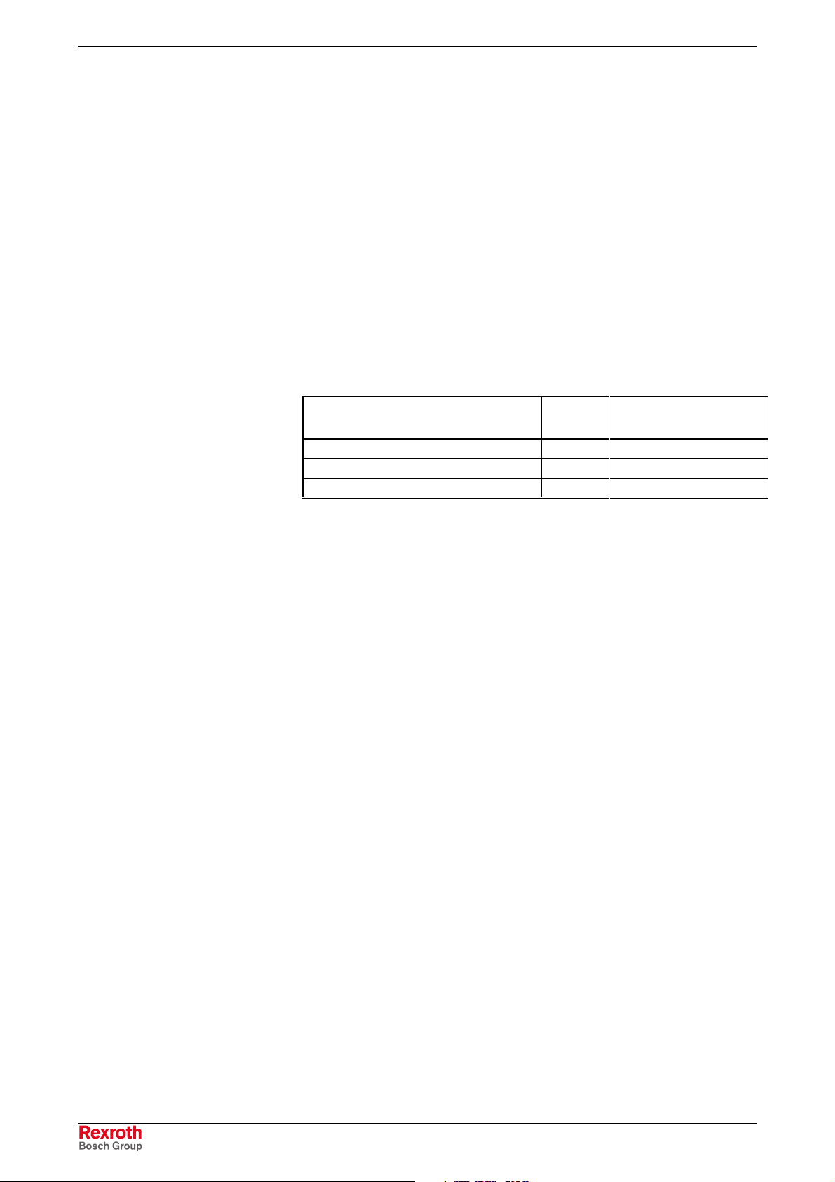
Distinguishing Features
The operator terminals are pr ovided as dif f er ent variants . Es s entially, they
differ in display seize and touch screen capability.
BTV 16.1 (Rexroth Indramat or
Bosch design)
BTV 16.1 (Rexroth design) BB BC BD
Display 12" TFT
Touch screen Yes Yes No
Fig. 1-1: Distinguishing features for the front of the IndraView P16
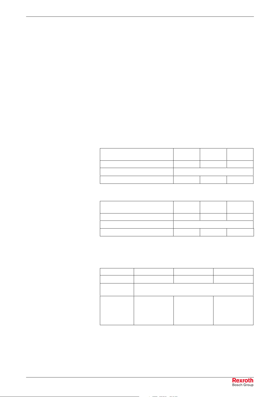
BTV 40.1 (Rexroth Indramat or
Bosch design)
BTV 40.1 (Rexroth design) BE BG BH
Display 15" TFT
Touch screen Yes Yes No
Fig. 1-2: Distinguishing features for the front of the IndraView P40
AB AC AD
AE AG AH
Every IndraView P16 (type BTV 16.1) is equipped with a PC box type A or
type C, an IndraView P40 (type BTV 40.1) can be equipped with the PC
box type A, type B or type C. The most important features are:
PC box Type A Type B Type C
Free slots 3 6 4
Power Supply 85 ... 264 VAC
or 24 VDC
Integrated UPS
Integrated
UPS_Logic,
battery pack to
be externally
connected
If desired
with integrated
battery pack
Integrated
UPS_Logic,
battery pack to
be externally
connected
Fig. 1-3: PC box, type A, B and C
DOK-SUPPL*-BTV16/40***-PR02-EN-P
1-2 System Presentation BTV 16/40
Operator Terminals with Keypad
The front panel with keypad consists of a 4 mm thick aluminum panel with
tapered edges covered by a chemical resistant polyester foil with
embossed keys. Machine functions keys (M-Keys) with separators
preventing the user from accidental key activation are integrated in the
user-oriented functional keypad.
Operator Terminals with Touch Screen
The front panel with touch screen allows to operate the application
software via the touch-sensitive surface of the display without keyboard
and mouse.
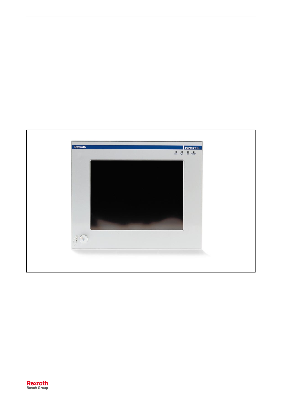
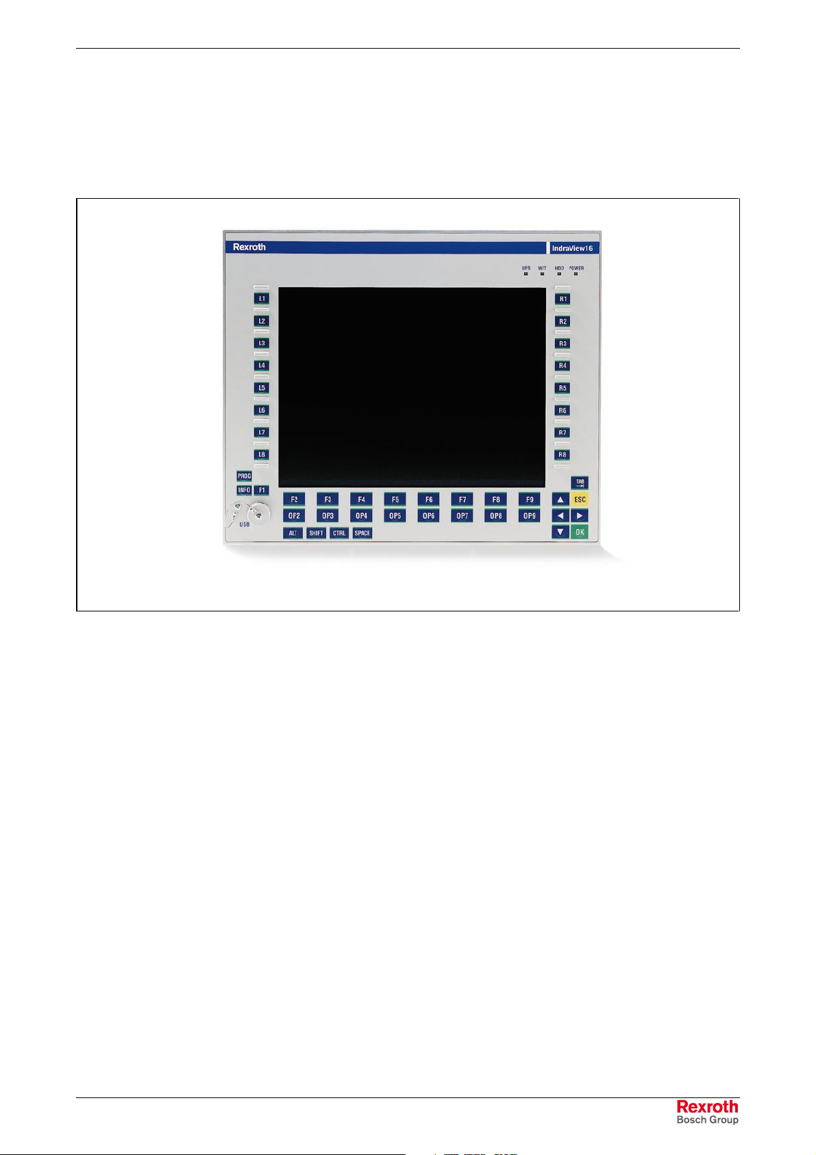
Variants IndraView P16 (BTV 16.1)
BTV 16.1BB with Touch Screen (Rexroth Design)
IndraViewP16_BB.eps
Fig. 1-4: BTV 16.1 with touch screen
BTV 16.1AB with Touch Screen (Bosch Design)
Comparable with BTV 16.1BB, but different coloring.
BTV 16.1BC with Touch Screen, Suitable for the Food
Industry, without Front USB (Rexroth Design)
BTV 16.1AC with Touch Screen, Suitable for the Food
Industry, without Front USB (Bosch Design)
These two variants are available for special applications, e.g. for the f ood
production, with special front panel.
Principally, they differ from the standard variant in its tapered edges, the
missing USB connection and the different mounting dimensions.
DOK-SUPPL*-BTV16/40***-PR02-EN-P
BTV 16/40 System Presentation 1-3
BTV 16.1BD with Keypad and 16 M-Keys, Standard
Versions (Rexroth Design)
BTV 16.1AD with Keypad and 16 M-Keys, Standard
Version (Rexroth Indramat Design)
Fig. 1-5: BTV 16.1 with keypad
IndraViewP16_AD.eps
DOK-SUPPL*-BTV16/40***-PR02-EN-P
1-4 System Presentation BTV 16/40
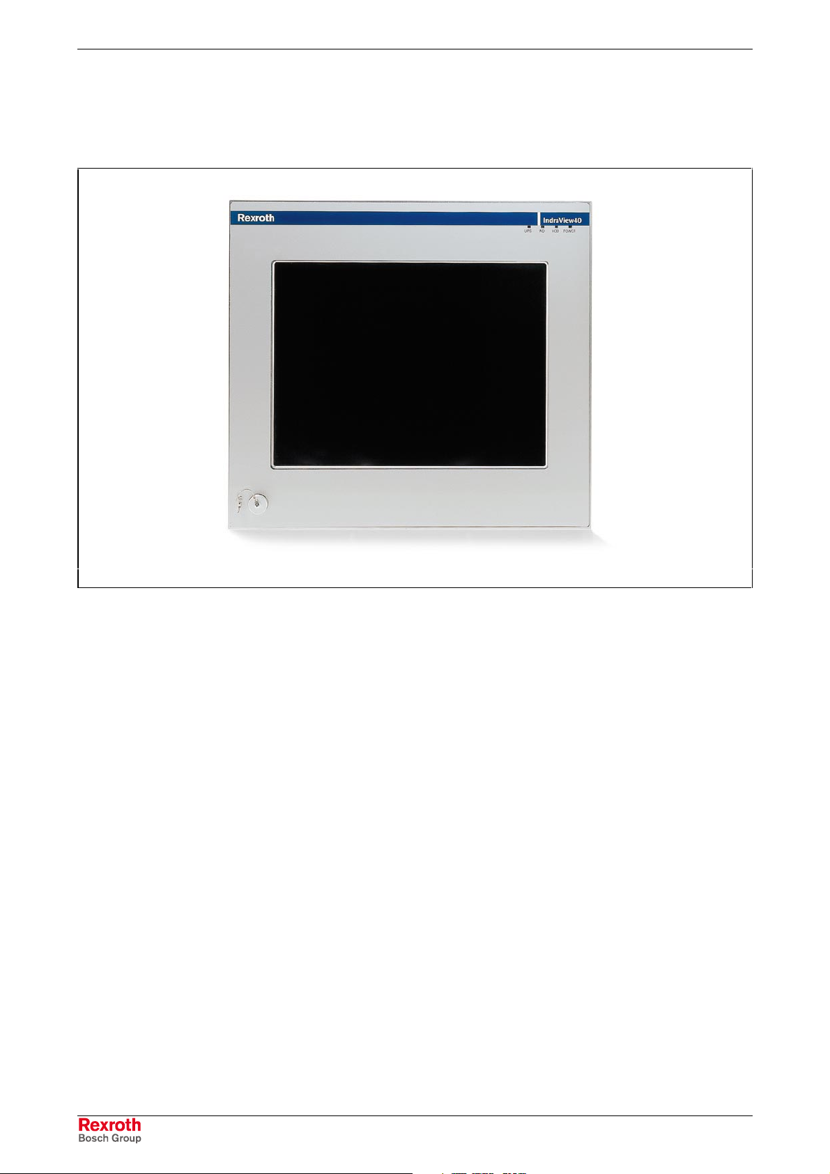
Variants IndraView P40 (BTV 40.1)
BTV 40.1BE with Touch Screen (Rexroth Design)
IndraViewP40_BE.eps
Fig. 1-6: BTV 40.1 with touch screen
BTV 40.1AE with Touch Screen (Bosch Design)
Similar device as BTV 40.1BB, but different coloring.
BTV 40.1BG with Touch Screen, Suitable for the Food
Industry, without Front USB (Rexroth Design)
BTV 40.1AG with Touch Screen, Suitable for the Food
Industry, without Front USB (Bosch Design)
These two variants are available for special applications, e.g. for the f ood
production, with special front panel. Principally, they differ from the
standard variant in its tapered edges, the missing USB connection and
the different mounting dimensions.
DOK-SUPPL*-BTV16/40***-PR02-EN-P
BTV 16/40 System Presentation 1-5
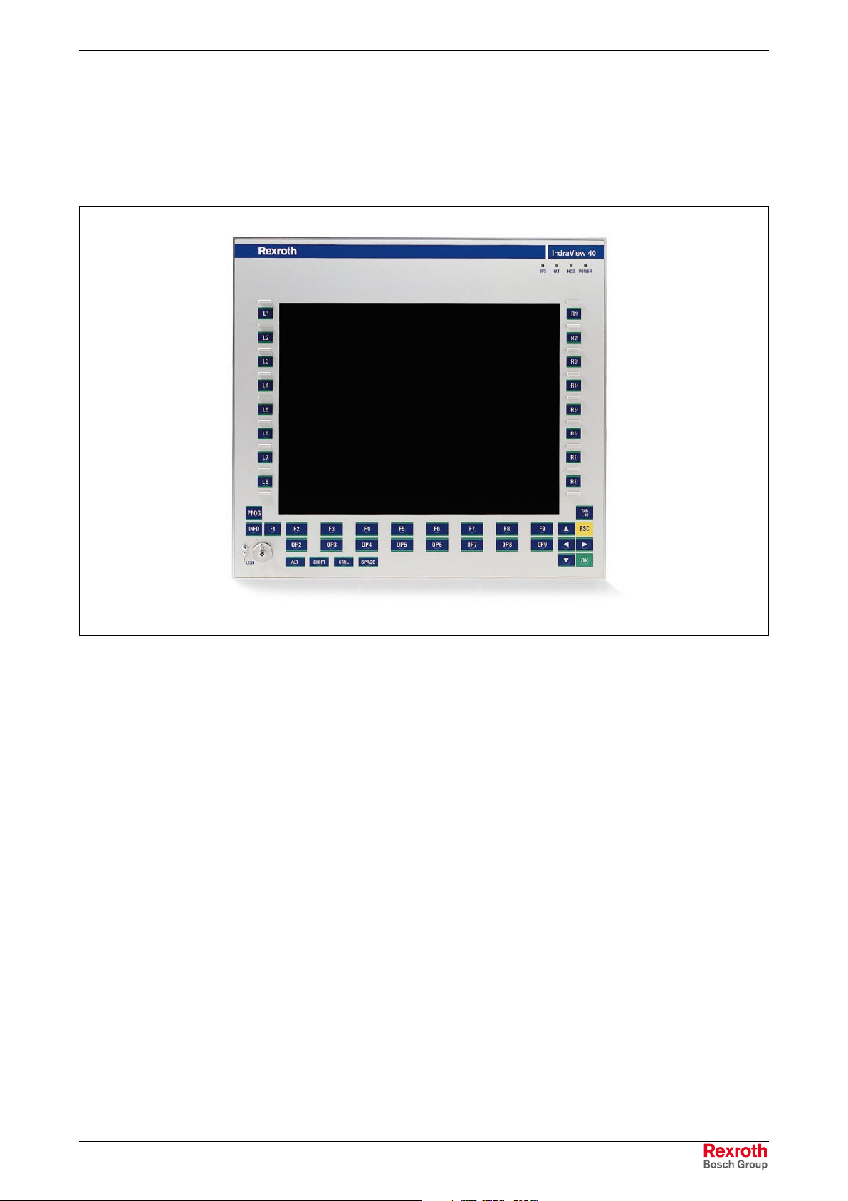
BTV 40.1BH with Keypad and 16 M-Keys, Standard
Version (Rexroth Design)
BTV 40.1AH with Keypad and 16 M-Keys, Standard
Version (Rexroth Indramat Design)
Fig. 1-7: BTV 40.1 with keypad
1.3 Operating System
For license reasons IndraView P16 and IndraView P40 are only delivered
with already installed operating system.
The delivered operating systems may only be used in the industrial
environment. Use in the office area, e.g. on a secretary’s computer, is not
allowed.
1.4 Commissioning
Mount the device properly (for this, see chapter 5 "Dimensions"). Then,
connect the device to the power supply and, if required, to the network.
IndraViewP40_AH.eps
DOK-SUPPL*-BTV16/40***-PR02-EN-P

1-6 System Presentation BTV 16/40
DOK-SUPPL*-BTV16/40***-PR02-EN-P

BTV 16/40 Important Directions for Use 2-1
2 Important Directions for Use
2.1 Appropriate Use
Introduction
Rexroth products represent state-of-the-art developments and
manufacturing. They are tested prior to delivery to ensure operating safety
and reliability.
The products may only be used in the manner that is defined as
appropriate. If they are used in an inappropriate manner, then situations
can develop that may lead to property damage or injury to personnel.
Note: Bosch Rexroth, as manuf ac tur er, is not liable f or any damages
resulting from inappropriate use. In s uch cases , the guarantee
and the right to payment of damages resulting from
inappropriate use are forfeited. The user alone carries all
responsibility of the risks.
Before using Rexroth products, mak e sure that all the pre-requisites for
appropriate use of the products are satisfied:
• Personnel that in any way, shape or form uses our pr oduc ts must firs t
read and understand the relevant safety instructions and be familiar
with appropriate use.
• If the produc t takes the form of hardware, then they must remain in
their original state, in other words, no structural changes are
permitted. It is not permitted to dec ompile software products or alter
source codes.
• Do not mount damaged or faulty products or use them in operation.
• Make sure that the products have been installed in the manner
described in the relevant documentation.
DOK-SUPPL*-BTV16/40***-PR02-EN-P

2-2 Important Directions for Use BTV 16/40
Areas of Use and Application
IndraView P16 (BTV 16.1) and IndraView P40 (BTV 40.1) are PC-based
machine and visualization terminals, that can – depending on the
application and configuration - also perf orm control functionalities. Thes e
operator terminals made by Bosch Rexroth are designed for use in the
following cases:
• as operator, visualization and programming terminal with integrated
soft control in stand-alone machines,
• as operator, visualization and programming terminal for connected
RECO controls.
Note: IndraView P16 (BTV 16.1) and IndraView P40 (BT V 40.1) may
only be used with the accessories and parts s pecified in this
document. If a component has not been specifically named,
then it may not be either mounted or connected. The same
applies to cables and lines.
Operation is only permitted in the specified configurations and
combinations of com ponents using the software and f irmware
as specified in the relevant function descriptions.
IndraView P16 (BTV 16.1) and IndraView P40 (BTV 40.1) are designed
for control tasks in an installation with multiple axes.
Available for an application-specific use of the terminals are unit types
with differing equipment and interfaces.
Typical areas of application of IndraView P16 (BTV 16.1) and
IndraView P40 (BTV 40.1) are:
• lathes
• milling machines and
• machining centers.
IndraView P16 (BTV 16.1) and IndraView P40 (BTV 40.1) may only be
operated under the assembly, installation and ambient conditions as
described here (temperature, system of protection, humidity, EMC
requirements, etc.) and in the position specified.
2.2 Inappropriate Use
Using the IndraView P16 (BTV 16.1) and IndraView P40 (BTV 40.1)
outside of the above-referenced areas of application or under operating
conditions other than described in the document and the technical data
specified is defined as “inappropriate use".
IndraView P16 (BTV 16.1) and IndraView P40 (BTV 40.1) may not be
used, if
• they are subject to operating conditions that do not meet the above
• Bosch Rexroth has not specifically released them for that intended
specified ambient conditions. This includes, for example, operation
under water, in the case of extreme temperature fluctuations or
extreme maximum temperatures or if
purpose. Please note the specifications outlined in the general Safety
Instructions!
DOK-SUPPL*-BTV16/40***-PR02-EN-P
BTV 16/40 Safety Instructions for Electric Drives and Controls 3-1
3 Safety Instructions for Electric Drives and Controls
3.1 Introduction
Read these instructions before the initial startup of the equipm ent in or der
to eliminate the risk of bodily harm or material damage. Follow these
safety instructions at all times.
Do not attempt to install or start up this equipm ent without first r eading all
documentation provided with the product. Read and understand these
safety instructions and all user docum entation of the equipment prior to
working with the equipment at any time. If you do not have the user
documentation for your equipment, contact your local Bosch Rexroth
representative to send this documentation immediately to the person or
persons responsible for the safe operation of this equipment.
If the equipment is resold, rented or transferred or passed on to others,
then these safety instructions must be delivered with the equipment.
Improper use of this equipment, failure to f ol l ow
the safety instructions in this document or
tampering with the product, including disabling
WARNING
of safety devices, may result in material
damage, bodily harm, electric shock or even
death!
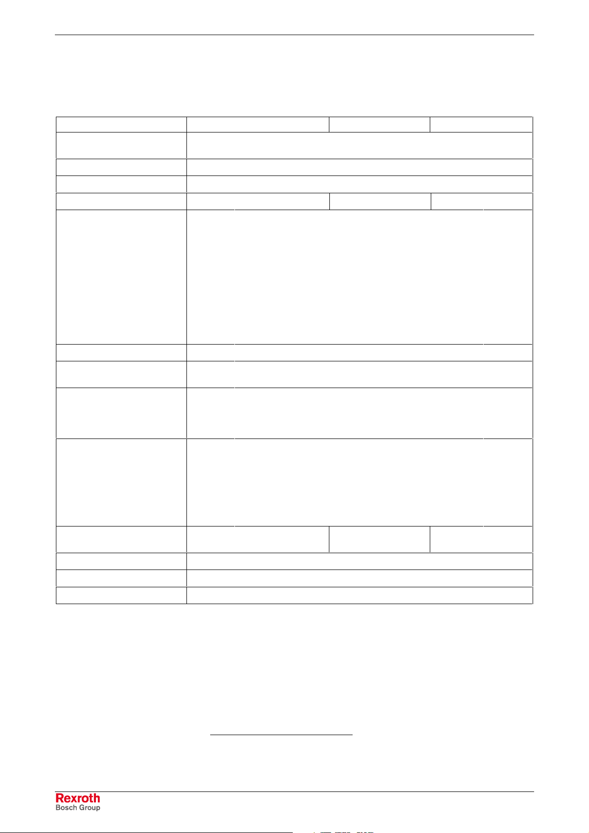
3.2 Explanations
The safety instructions describe the following degrees of hazard
seriousness in compliance with ANSI Z535. The degree of hazard
seriousness informs about the consequences resulting from noncompliance with the safety instructions.
Warning symbol with signal
word
DANGER
WARNING
CAUTION
Degree of hazard seriousness according
to ANSI
Death or severe bodily harm will occur.
Death or severe bodily harm may occur.
Bodily harm or material damage may occur.
Fig. 3-1: Hazard classification (according to ANSI Z535)
DOK-SUPPL*-BTV16/40***-PR02-EN-P
3-2 Safety Instructions for Electric Drives and Controls BTV 16/40
3.3 Hazards by Improper Use
High voltage and high discharge current!
Danger to life or severe bodily harm by electric
shock!
DANGER
Dangerous movements! Danger to life, severe
bodily harm or material damage by
unintentional motor movements!
DANGER
High electrical voltage due to wrong
connections! Danger to life or bodily harm by
electric shock!
WARNING
WARNING
CAUTION
CAUTION
Health hazard for persons with heart
pacemakers, metal implants and hearing aids i n
proximity to electrical equipment!
Surface of machine housing could be extremely
hot! Danger of injury! Danger of burns!
Risk of injury due to improper handling! Bodily
harm caused by crushing, shearing, cutting and
mechanical shock or incorrect handling of
pressurized systems!
CAUTION
Risk of injury due to incorrect handling of
batteries!
DOK-SUPPL*-BTV16/40***-PR02-EN-P

BTV 16/40 Safety Instructions for Electric Drives and Controls 3-3
3.4 General Information
• Bosch Rexroth AG is not liable for dam ages resulting from failure to
observe the warnings provided in this documentation.
• Read the operating, maintenance and safety instructions in your
language before starting up the machine. If you f ind that you cannot
completely understand the documentation for your product, please ask
your supplier to clarify.
• Proper and correct transport, storage, assembly and installation as
well as care in operation and maintenance are prerequisites for
optimal and safe operation of this equipment.
• Only persons who are trained and qualified for the use and operation
of the equipment may work on this equipment or within its proximity.
• The persons are qualified if they have suffic ient knowledge of the
assembly, installation and operation of the equipm ent as well as an
understanding of all warnings and precautionary measures noted in
these instructions.
• Furthermore, they must be trained, instructed and qualified to
switch electrical circuits and equipment on and off in accordance
with technical safety regulations, to ground them and to mark them
according to the requirements of safe work practices. They must
have adequate safety equipment and be trained in first aid.
• Only use spare parts and accessories approved by the manufacturer.
• Follow all safety regulations and requirements for the specific
application as practiced in the country of use.
• The equipment is designed for installation in industrial machinery.
• The ambient conditions given in the product docum entation must be
observed.
• Use only safety features and applications that are clearly and explicitly
approved in the Project Planning Manual.
For example, the following areas of use are not permitted: construction
cranes, elevators used for people or freight, devices and vehicles to
transport people, medical applications, refinery plants, transport of
hazardous goods, nuclear applications, applications sensitive to high
frequency, mining, food processing, control of protection equipment
(also in a machine).
• The information given in the documentation of the product with r egard
to the use of the delivered components contains only examples of
applications and suggestions.
The machine and installation manufacturer must
• make sure that the delivered components are suited for his
individual application and check the information given in this
documentation with regard to the use of the components,
• m ake sure that his application c omplies with the applicable safety
regulations and standards and carry out the required measures,
modifications and complements.
• Startup of the delivered components is only permitted once it is sure
that the machine or installation in which they are installed complies
with the national regulations, safety specifications and standards of the
application.
• Technical data, connections and operational conditions are specified in
the product documentation and must be followed at all times.
DOK-SUPPL*-BTV16/40***-PR02-EN-P
3-4 Safety Instructions for Electric Drives and Controls BTV 16/40
• Operation is only permitted if the national EMC regulations for the
application are met.
The instructions for installation in accordanc e with EMC requirements
can be found in the documentation "EMC in Drive and Control
Systems".
The machine or installation manufacturer is responsible for
compliance with the limiting values as prescribed in the national
regulations.
3.5 Protection Against Contact with Electrical Parts
Note: This section refers to equipment and drive components with
voltages above 50 Volts.
Touching live parts with voltages of 50 Volts and m ore with bare hands or
conductive tools or touching ungrounded housings can be dangerous and
cause electric shock. In order to operate electrical equipment, certain
parts must unavoidably have dangerous voltages applied to them.
DANGER
High electrical voltage! Danger to life, severe
bodily harm by electric shock!
⇒ Only those trained and qualified to work with or on
electrical equipment are perm itted to operate, maintain
or repair this equipment.
⇒ Follow general construction and safety regulations when
working on high voltage installations.
⇒ Before switching on power the ground wire must be
permanently connected to all electrical units according
to the connection diagram.
⇒ Do not operate electrical equipment at any time, even
for brief measurem ents or tests , if the gr ound wire is not
permanently connected to the points of the com ponents
provided for this purpose.
⇒ Before work ing with electrical parts with voltage higher
than 50 V, the equipment must be disconnected from
the mains voltage or power supply. Make sure the
equipment cannot be switched on again unintended.
⇒ The following should be observed with electrical drive
and filter components:
⇒ W ait five (5) minutes after switching off power to allow
capacitors to discharge before beginning to work.
Measure the voltage on the capacitors before beginning
to work to make sure that the equipment is safe to
touch.
⇒ Never touch the electrical connection points of a
component while power is turned on.
⇒ Install the covers and guards provided with the
equipment properly before switching the equipment on.
Prevent contact with live parts at any time.
⇒ A residual-current-operated protective device (RCD)
must not be used on electric drives! Indirect contact
must be prevented by other means, for example, by an
overcurrent protective device.
⇒ Electrical components with exposed live parts and
uncovered high voltage terminals mus t be installed in a
protective housing, for example, in a control cabinet.
DOK-SUPPL*-BTV16/40***-PR02-EN-P
BTV 16/40 Safety Instructions for Electric Drives and Controls 3-5
To be observed with electrical drive and filter components:
High electrical voltage on the housing!
High leakage current! Danger to life, danger of
injury by electric shock!
DANGER
⇒ Connect the electrical equipment, the housings of all
electrical units and motors permanently with the safety
conductor at the ground points before power is
switched on. Look at the connection diagram. This is
even necessary for brief tests.
⇒ Connect the safety conductor of the electrical
equipment always permanently and firmly to the
supply mains. Leakage current exceeds 3.5 mA in
normal operation.
⇒ Use a copper conductor with at least 10 mm² cross
section over its entire course for this saf ety conductor
connection!
⇒ Prior to startups , even for brief tests, always connect
the protective conductor or connect with ground wire.
Otherwise, high voltages can occur on the housing
that lead to electric shock.
3.6 Protection Against Electric Shock by Protective Low Voltage (PELV)
All connections and terminals with voltages between 0 and 50 Volts on
Rexroth products are protective low voltages designed in accordance with
international standards on electrical safety.
High electrical voltage due to wrong
connections! Danger to life, bodily harm by
electric shock!
WARNING
⇒ Only connect equipment, electrical components and
cables of the protective low voltage type (PELV =
Protective Extra Low Voltage) to all terminals and
clamps with voltages of 0 to 50 Volts.
⇒ Only electrical circuits may be connected which are
safely isolated against high voltage circuits. Safe
isolation is achieved, for example, with an isolating
transformer, an opto-electronic coupler or when
battery-operated.
DOK-SUPPL*-BTV16/40***-PR02-EN-P
3-6 Safety Instructions for Electric Drives and Controls BTV 16/40
3.7 Protection Against Dangerous Movements
Dangerous movements can be caused by faulty control of the connected
motors. Some common examples are:
• improper or wrong wiring of cable connections
• incorrect operation of the equipment components
• wrong input of parameters before operation
• malfunction of sensors, encoders and monitoring devices
• defective components
• software or firmware errors
Dangerous movements can occur immediately after equipment is
switched on or even after an unspecified time of trouble-free operation.
The monitoring in the drive components will normally be sufficient to avoid
faulty operation in the connected drives. Regarding personal safety,
especially the danger of bodily injury and material damage, this alone
cannot be relied upon to ensure complete safety. Until the integrated
monitoring functions becom e effective, it must be assumed in any case
that faulty drive movements will occur. The extent of faulty drive
movements depends upon the type of control and the state of operation.
DANGER
Dangerous movements! Danger to life, risk of
injury, severe bodily harm or material damage!
⇒ Ensure personal safety by means of qualified and
tested higher-level monitoring devices or measures
integrated in the installation. Unintended machine
motion is possible if monitoring devices are disabled,
bypassed or not activated.
⇒ Pay attention to unintended machine m otion or other
malfunction in any mode of operation.
⇒ Keep free and clear of the machine’s range of m otion
and moving parts. Possible measures to prevent
people from accidentally entering the machine’s r ange
of motion:
- use safety fences
- use safety guards
- use protective coverings
- install light curtains or light barriers
⇒ Fences and coverings must be strong enough to
resist maximum possible momentum, especially if
there is a possibility of loose parts flying off.
⇒ Mount the emergency stop switch in the immediate
reach of the operator. Verify that the emer gency stop
works before startup. Don’t operate the machine if the
emergency stop is not working.
⇒ Isolate the drive power connection by means of an
emergency stop circuit or use a starting lockout to
prevent unintentional start.
Make sure that the drives are brought to a safe
standstill before accessing or entering the danger
zone. Safe standstill can be achieved by switching
off the power supply contactor or by safe mechanical
locking of moving parts.
DOK-SUPPL*-BTV16/40***-PR02-EN-P
BTV 16/40 Safety Instructions for Electric Drives and Controls 3-7
⇒ Secure vertical axes against falling or dropping after
switching off the motor power by, for example:
- mechanically securing the vertical axes
- adding an external braking/ arrester/ clamping
mechanism
- ensuring sufficient equilibration of the vertical axes
The standard equipment m otor brake or an external
brake controlled directly by the drive controller are
not sufficient to guarantee personal safety!
⇒ Dis connect electrical power to the equipment using a
master switch and secure the switch against
reconnection for:
- maintenance and repair work
- cleaning of equipment
- long periods of discontinued equipment use
⇒ Prevent the operation of high-frequency, remote
control and radio equipment near electronics circuits
and supply leads. If the use of such equipment cannot
be avoided, verify the system and the installation for
possible malfunctions in all possible positions of
normal use before initial startup. If necess ary, perform
a special electromagnetic compatibility (EMC) test on
the installation.
3.8 Protection Against Magnetic and Electromagnetic Fields During Operation and Mounting
Magnetic and electromagnetic fields generated near current-carrying
conductors and permanent m agnets in m otors represent a ser ious health
hazard to persons with heart pacemakers, metal implants and hearing
aids.
Health hazard for persons with heart
pacemakers, metal implants and hearing aids i n
proximity to electrical equipment!
WARNING
⇒ Persons with heart pacemakers, hearing aids and
metal implants are not perm itted to enter the following
areas:
- Areas in which electrical equipm ent and parts are
mounted, being operated or started up.
- Areas in which parts of motors with permanent
magnets are being stored, operated, repaired or
mounted.
⇒ If it is necess ary for a person with a heart pacemak er
to enter such an area, then a doctor must be
consulted prior to doing so. Heart pacemakers that
are already implanted or will be implanted in the
future, have a considerable variation in their electric al
noise immunity. Therefore there are no rules with
general validity.
⇒ Persons with hearing aids, metal implants or metal
pieces must consult a doctor before they enter the
areas described above. Otherwise, health hazards will
occur.
DOK-SUPPL*-BTV16/40***-PR02-EN-P
3-8 Safety Instructions for Electric Drives and Controls BTV 16/40
3.9 Protection Against Contact with Hot Parts
Housing surfaces could be extremely hot!
Danger of injury! Danger of burns!
⇒ Do not touch housing surfaces near sources of heat!
CAUTION
Danger of burns!
⇒ After switching the equipment off, wait at least ten (10)
minutes to allow it to cool down before touching it.
⇒ Do not touch hot parts of the equipment, such as
housings with integrated heat sinks and resistors.
Danger of burns!
3.10 Protection During Handling and Mounting
Under certain conditions, incorrect handling and mounting of parts and
components may cause injuries.
CAUTION
Risk of injury by incorrect handling! Bodily
harm caused by crushing, shearing, cutting and
mechanical shock!
⇒ Observe general installation and safety instructions
with regard to handling and mounting.
⇒ Use appropriate mounting and transport equipment.
⇒ Take precautions to avoid pinching and crushing.
⇒ Use only appropriate tools. If specified by the product
documentation, special tools must be used.
⇒ Use lifting devices and tools correctly and safely.
⇒ For safe protection wear appropriate protective
clothing, e.g. safety glasses, safety shoes and saf ety
gloves.
⇒ Never stand under suspended loads.
⇒ Clean up liquids from the f loor imm ediately to prevent
slipping.
DOK-SUPPL*-BTV16/40***-PR02-EN-P
BTV 16/40 Safety Instructions for Electric Drives and Controls 3-9
3.11 Battery Safety
Batteries contain reactive chemicals in a solid housing. Inappropriate
handling may result in injuries or material damage.
Risk of injury by incorrect handling!
⇒ Do not attempt to reactivate discharged batteries by
heating or other methods (danger of explosion and
CAUTION
Note: Be aware of environmental protection and disposal! The
batteries contained in the product should be considered as
hazardous material for land, air and sea trans port in the sense
of the legal requirements (danger of explosion). Dispose
batteries separately from other waste. Observe the legal
requirements in the country of installation.
cauterization).
⇒ Never charge non-chargeable batteries (danger of
leakage and explosion).
⇒ Never throw batteries into a fire.
⇒ Do not dismantle batteries.
⇒ Do not damage electrical com ponents installed in the
equipment.
3.12 Protection Against Pressurized Systems
Certain motors and drive controllers, corres ponding to the information in
the respective Project Planning Manual, must be provided with
pressurized media, such as compressed air, hydraulic oil, cooling fluid
and cooling lubricant supplied by external systems. Inc orrect handling of
the supply and connections of pressurized systems can lead to injuries or
accidents. In these cases, improper handling of external supply systems,
supply lines or connections can cause injuries or material damage.
Danger of injury by incorrect handling of
pressurized systems !
⇒ Do not attempt to disassemble, to open or to cut a
CAUTION
pressurized system (danger of explosion).
⇒ Observe the operation instructions of the respective
manufacturer.
⇒ Before disassembling pressurized systems, release
pressure and drain off the fluid or gas.
⇒ Use suitable protective clothing (for example safety
glasses, safety shoes and safety gloves)
⇒ Remove any fluid that has leaked out onto the floor
immediately.
Note: Environmental protection and disposal! T he m edia used in the
DOK-SUPPL*-BTV16/40***-PR02-EN-P
operation of the pressurized system equipment may not be
environmentally compatible. Media that are damaging the
environment mus t be disposed separately from nor mal waste.
Observe the legal requirements in the country of installation.

3-10 Safety Instructions for Electric Drives and Controls BTV 16/40
Notes
DOK-SUPPL*-BTV16/40***-PR02-EN-P

BTV 16/40 Technical Data 4-1
4 Technical Data
4.1 Front Panel
BTV 16.1BB BTV 16.1BC BTV 16.1BD
Display
Operation
Surface – Front panel
Degree of protection
Interface
Display
Operation
Surface – Front panel
Degree of protection
Interface
Touch screen Keypad
Front panel IP 65 according to DIN 40 050, IEC 529
USB connection, Cover’s
degree of protection IP 65
Fig. 4-1: Technical data: front of the IndraView P16 (Rexroth design)
BTV 16.1AB BTV 16.1AC BTV 16.1AD
Touch screen Keypad
Graphite gray
(Bosch design)
Front panel IP 65 according to DIN 40 050, IEC 529
USB connection, Cover’s
degree of protection IP 65
12"-TFT, 800 x 600 pixel
256.000 colors
Color: RAL 7035 light gray
No USB connection USB connection, Cover’s
degree of protection IP 65
12"-TFT, 800 x 600 pixel
256.000 colors
Color: RAL 7035 light gray
(Rexroth Indramat design)
No USB connection USB connection, Cover’s
degree of protection IP 65
Display
Operation
Surface – Front panel
Degree of protection
Interface
Display
Operation
Surface – Front panel
Degree of protection
Interface
Fig. 4-2: Technical data: front of the IndraView P16
(Rexroth Indramat or Bosch design)
BTV 40.1BE BTV 40.1BG BTV 40.1BH
15"-TFT, 1024 x 768 pixel
256.000 colors
Touch screen Keypad
Color: RAL 7035 light gray
Front panel IP 65 according to DIN 40 050, IEC 529
USB connection, Cover’s
degree of protection IP 65
Fig. 4-3: Technical data: front of the IndraView P16 (Rexroth design)
BTV 40.1AE BTV 40.1AG BTV 40.1AH
Touch screen Keypad
Graphite gray
(Bosch design)
Front panel IP 65 according to DIN 40 050, IEC 529
USB connection, Cover’s
degree of protection IP 65
No USB connection USB connection, Cover’s
degree of protection IP 65
15"-TFT, 1024 x 768 pixel
256.000 colors
Color: RAL 7035 light gray
(Rexroth Indramat design)
No USB connection USB connection, Cover’s
degree of protection IP 65
Fig. 4-4: Technical data: front of the IndraView P40
DOK-SUPPL*-BTV16/40***-PR02-EN-P
(Rexroth Indramat or Bosch design)
4-2 Technical Data BTV 16/40
4.2 PC Box
PC box Type A Type B Type C
Processor
Working memory
Hard disk
Optional drives
Pentium III with minimum 400 MHz and integrated graphic controller
with maximum 8 MB video memory
Max. 256 MB
Min. 5 GB
CD ROM None CD ROM
Interfaces
available in all variants
Additional interfaces
For variant without
special interfaces
For variant with
PROFIBUS DP slave
and 24 V I/O
For variant with
SIS and BT bus
Slots
Degree of protection
Power supply
Max. power consumption
• 1 x parallel interface (25-pin, D-Sub)
• 1 x external VGA connection (15-pin, HD-Sub)
• 2 x USB connection (type A)
• 1 x Ethernet connection (RJ 45, 10/100 Base-T)
• 1 x keyboard connection (PS/2)
• 1 x mouse connection (PS/2)
• 1 x external battery connection
• 1 x floppy disk connection
• 2 to 3 serial standard interfaces RS232 (9-pin, D-Sub)
• 2 to 3 serial standard interfaces RS232 (9-pin, D-Sub)
• 1 x PROFIBUS DP slave (9-pin, D-Sub)
• 1 x 24 V I/O
• 1 x serial standard interface RS232 (9-pin, D-Sub)
• 1 x serial multi-mode interface RS232, RS422, RS485
SIS (15-pin, D-Sub) (SIS interface according to Rexroth
standard)
• 1 x BT bus master (9-pin, D-Sub)
• 1 x "Ready" relay contact (3-pin, Weidmüller)
2 x PCI, 1 x PCI / ISA 2 x PCI, 1x PCI / ISA,
3 x ISA
PC box IP 00
85/264 VAC or 24 VDC
125 W
1
1
2
3 x PCI, 1 x PCI / ISA
Fig. 4-5: Technical data: PC box
1
For devices with touch screen 2 serial interfaces
2
For devices with touch screen no serial interface
DOK-SUPPL*-BTV16/40***-PR02-EN-P
BTV 16/40 Technical Data 4-3
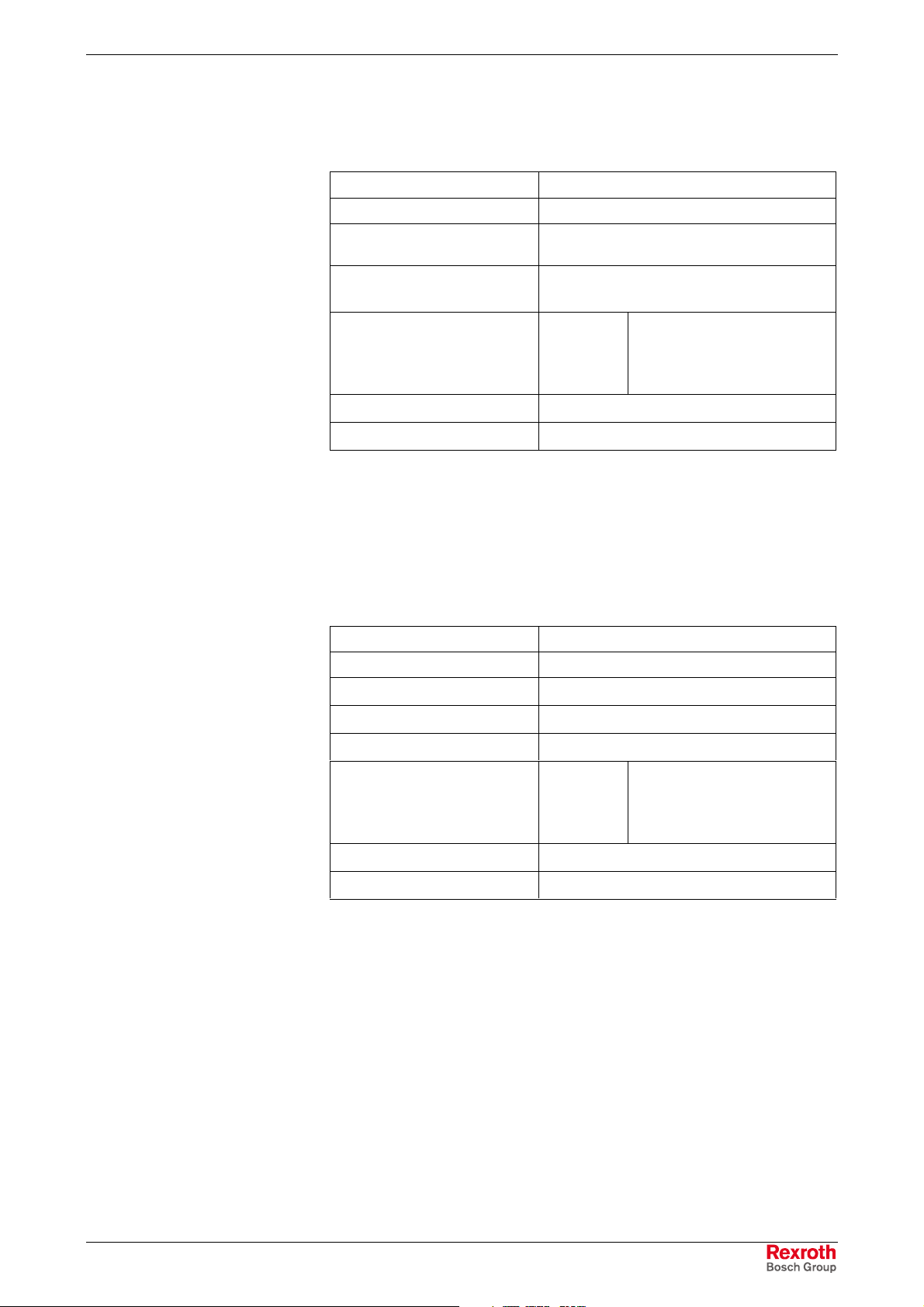
4.3 Power Supply Unit 115 V / 230 V
Nominal input voltage: 115 VAC / 230 VAC
Input voltage range: 85 ... 264 VAC
Input current:
Max. inrush current
(cold start 25 °C)
Output voltages:
+ 5 V
+ 12 V
Max. output power:
Efficiency:
*) Note: During specifying the maximum output currents please observe that the c urrents
separately considered are the maximum pos sible currents of the respect ive output volt age.
However, it is not possible to create the m aximum c urrent f rom both out put volt ages, as t he
maximum total output power (= 100 W) must not be exceeded.
Fig. 4-6: Technical data of the power supply unit 115 V / 230 V
0,7 A for nominal voltage 230 VAC
1,4 A for nominal voltage 115 VAC
30 A for nominal voltage 230 VAC
15 A for nominal voltage 115 VAC
Current
(max.)*
16 A
3 A
100 W*
0,8
Tolerance (incl. residual ripple)
+/- 5 %
+/- 5 %
4.4 Technical Data of the Power Supply Unit 24 V
Nominal input voltage: 24 VDC
Input voltage range: 24 VDC +20%, -15%
Noise and surge immunity:
Max. input current:
Max. inrush current:
Output voltages:
+ 5 V
+ 12 V
Max. output power:
Efficiency:
*) Note: During specifying the maximum output currents please observe that the c urrents
separately considered are the maximum pos sible currents of the respect ive output volt age.
However, it is not possible to create the m aximum c urrent f rom both out put volt ages, as t he
maximum total output power (= 80 W) must not be exceeded.
Fig. 4-7: Technical data of the power supply unit 24 V
Umax = 35 V (for t < 100 ms)
4 A for nominal voltage 24 V
25 A for nominal voltage 24 V
Current
(max.)*
11 A
3 A
80 W*
0,8
Tolerance (incl. residual ripple)
+/- 5 %
+/- 5 %
DOK-SUPPL*-BTV16/40***-PR02-EN-P

4-4 Technical Data BTV 16/40
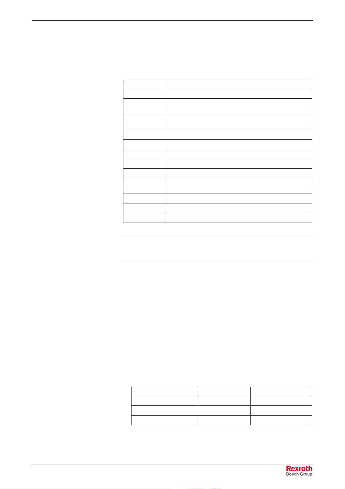
4.5 Ambient Conditions
In operation Storage/transport
Max. ambient temperature + 5 ... +45 °C -20 °C to +60 °C
Max. temperature gradient Temporal temperature changes up to 3
°C per minute
Relative humidity Climatic class 3K3 according to
EN 60721, condensation not permissible.
Air pressure Up to 2000 m above sea level according
to DIN 60204
Mechanical strength Max. vibration:
Frequency range: 10 ... 150 Hz
Excursion: 0.075 mm
for 10 ... 57 Hz
Acceleration: 1 g
for 57 ... 150 Hz
according to EN 60068-2-6
Not defined
Climatic class 3K3 according to
EN 60721, condensation not
permissible.
Max. shock:
15 g according to
DIN IEC 68-2-27,
no disturbance of the function
Fig. 4-8: Ambient conditions
4.6 Compatibility Test
All Rexroth controls and drives are developed and tested ac cording to the
technological state-of-the-art.
As it is impossible to follow the continuing development of all materials
(e.g. lubricants in machine tools) which may interact with our controls and
drives, it cannot be completely ruled out that any reactions with the
materials used by Bosch Rexroth might occur.
For this reason, before using the respec tive material a compatibility test
has to be carried out for new lubricants, cleaning agents etc. and our
housings/our housing materials.
DOK-SUPPL*-BTV16/40***-PR02-EN-P
BTV 16/40 Technical Data 4-5
4.7 Used Standards
The system components of the operator terminals correspond to the
following standards:
Standard Meaning
EN 60 204-1 Electrical equipment of machines
EN 50 081-2 Basic technical standard, emitted interference (industrial
environment)
EN 50 082-2 Basic technical standard, noise immunity (industrial
environment)
EN 60 742 Transformer for 24 V power supply unit, protective separation
EN 60 950 Overvoltage category II
EN 61 131 Requirements concerning the 24 V outputs
EN 61 131-2 Requirements concerning the 24 power supply
EN 418 Machine safety, EMERGENCY STOP devices
EN 60 529 Degrees of protection (incl. housings and installation
compartments)
EN 60 068-2-6 Vibration test
EN 60068-2-27 Shock test
.IS.114 X-ray radiation directive according to Official Federal Gazette
4.8 Wear Parts
Wear parts without warranty
Fig. 4-9: Used standards
Note: Concerning delivered operator terminals all CE requirements
are fulfilled. After plugging-in ex tension cards , however, a new
CE test has to be executed.
• The service life of the backlight is limited to a certain number of
operating hours. After this time the backlight will produce only 50 % of
its original brightness. This time differs for the used displays:
• 12“: 40,000 hours
• 15“: 35,000 hours
• CMOS battery: 5 to 7 years
• Battery pack: The num ber of charging cycles of the battery pack and
thus, its service life is dependent on the ambient temperature, in which
the battery pack is used. Ambient temperature is defined as the
temperature, in which the operator terminal or the battery pack is
situated, e.g. the internal temperature of the control cabinet or in a
operator panel housing.
Ambient temperature Charging cycles Maintenance interval
25 °C 4000 cycles 6 years
35 °C 2000 cycles 3 years
45 °C 1000 cycles 1.5 years
DOK-SUPPL*-BTV16/40***-PR02-EN-P
Fig. 4-10: Battery pack
If you don’t exactly k now the conditions, Bosch Rexroth recomm ends
to exchange the battery pack every 1.5 years.
4-6 Technical Data BTV 16/40
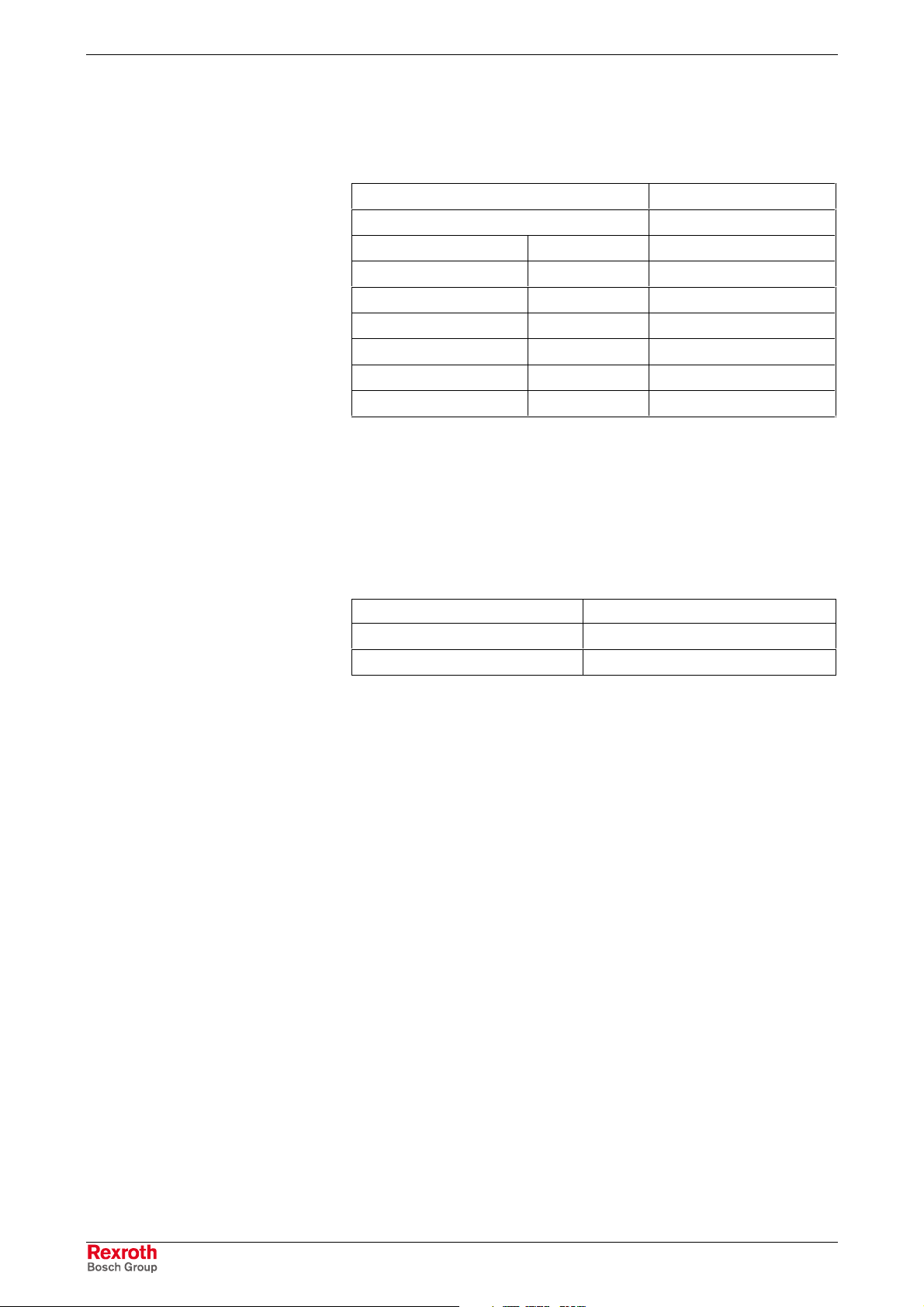
• Hard disk: The hard disk is an electromechanic wear part that has to
be changed during the operating time. According to the manufacturer’s
specifications the hard disk has been developed for a servic e life of 60
months in consideration of the following conditions:
Operating hours / month Max. 333
Input/output cycles / month Min. 10 and max. 150
Operating conditions Temperature 40 °C
Rel. humidity 30 %
Height < 500 m
Accesses 30 % of the operating hours
Storage conditions Temperature < 30 °C
Rel. humidity < 70 %
Duration < 3 months
Fig. 4-11: Typical operating and storage conditions of the hard disk
The operation out of this typical conditions is permissible, whereby,
however, the service life of the hard disk may be reduced. However,
the ambient conditions specified for the overall device in c hapter 4.5
have to be absolutely kept.
• Also fans are mechanic wear components, whose service life is
extremely temperature-dependent. For the fan integrated in the
housing the manufacturer specifies the following service life:
Ambient temperature Service life
40 °C 70,000 hours
70 °C 35,000 hours
Fig. 4-12: Service life of the fan
DOK-SUPPL*-BTV16/40***-PR02-EN-P
 Loading...