

Bosch Rexroth A7VO 63 User Manual
Axial piston variable pump
A7VO Series 63
RE 92202
Edition: 02.2015
Replaces: 05.2012
▶ Sizes 28 to 160
▶ Nominal pressure 350bar
▶ Maximum pressure 400bar
▶ Open circuit
Characteristics
▶ Variable pump with axial tapered piston rotary group of
bent-axis design, for hydrostatic drives in open circuit
▶ For use in mobile and stationary applications
▶ Flow is proportional to the drive speed and displace-
ment.
▶ The flow can be steplessly changed by adjusting the
bent axis.
▶ Wide selection of control devices
▶ Compact, robust pump with a long service life
Contents
Ordering code 2
Hydraulic fluids 4
Shaft seal ring 5
Flow direction 5
Operating pressure range 6
Technical data 7
LR – Power controller without power override 9
LA1 – Power controller with hydraulically
proportional power override 13
DR – Pressure controller 15
HD – Proportional hydraulic control 18
EP – Proportional electric control 20
Dimensions, size 28 21
Dimensions, size 55 24
Dimensions, size 80 28
Dimensions, size 107 32
Dimensions, size 160 36
Connector for solenoids 40
Installation instructions 41
Project planning notes 42
Safety instructions 42
RE 92202/02.2015, Bosch Rexroth AG
2 A7VO Series 63 | Axial piston variable pump
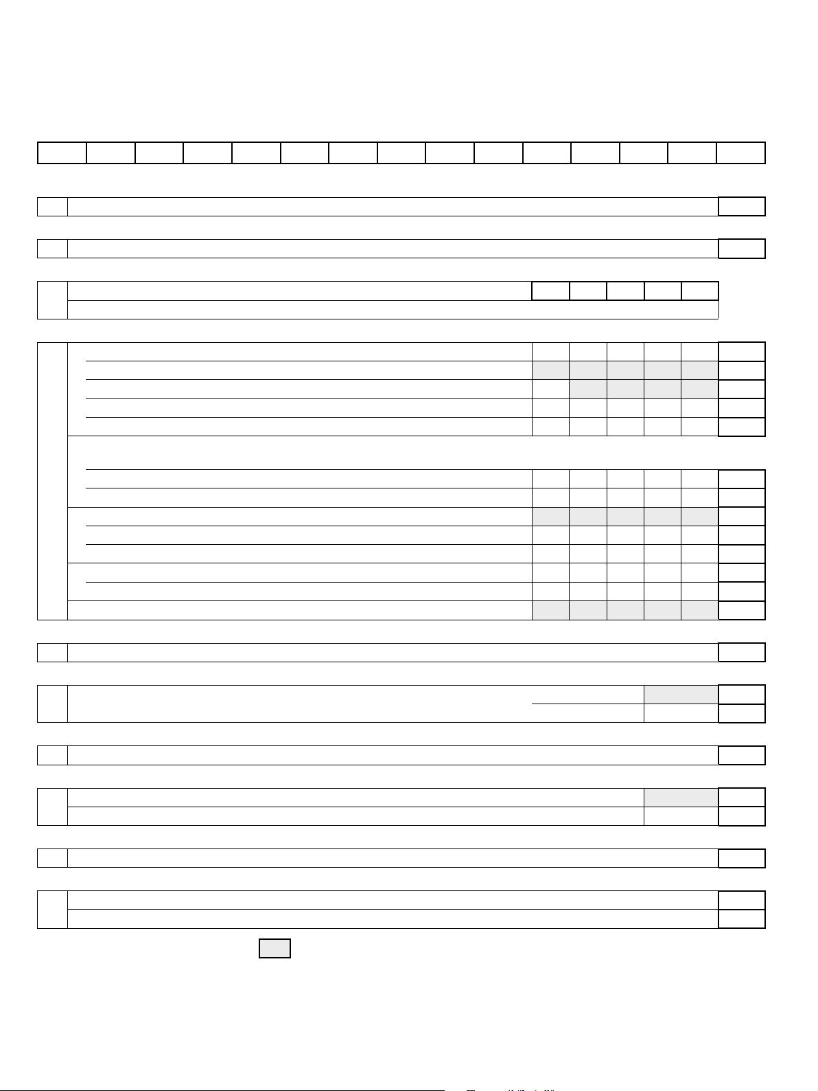
Ordering code
Ordering code
01 02 03 04 05 06 07 08 09 10 11 12 13
A7V O / 63 – V B 01
Axial piston unit
01 Bent-axis design, variable, nominal pressure 350 bar, maximum pressure 400 bar
Operating mode
02 Pump, open circuit
Size (NG)
03
Geometric displacement V
For sizes 250, 355 and 500, see data sheet 92203
Control device 28 55 80 107 160
04 Power controller without power override ● ● ● ● ●
with pressure cut-off ● ● ● ● ●
with stroke limiter negative control
with pressure cut-off and stroke limiter negative control
with pressure cut-off and load sensing – ● ● ● ● LRDS
Power controller with hydraulically proportional power override
(only available for clockwise rotation and with port plate 02)
with load sensing – ● ● – – LA1S
with load sensing and hydraulically proportional LS-override – ● ● – – LA1S5
Pressure controller ● ● ● ● ●
remotely controlled ● ● ● ● ●
with load sensing – ● ● ● ●
Proportional control hydraulic Positive control
with pressure cut-off, remotely controlled Positive control
Proportional control electrical
(cm3), see “Technical data” on page 7
g
Positive control
Δp = 25 bar
Δp = 25 bar
Δp = 10 bar
Δp = 10 bar
U = 24 V
28 55 80 107 160
– ● ● ● ●
– ● ● ● ●
● ● ● ● ●
● ● ● ● ●
● ● ● ● ● EP2
A7V
O
LR
LRD
LRH
LRDH1
DR
DRG
DRS
HD1
HD1G
Series
05 Series 6, index 3
Direction of rotation
06 Viewed on drive shaft clockwise ●
counter-clockwise ●
Sealing material
07 FKM (fluoroelastomer)
Drive shaft
08 Splined shaft DIN 5480 ●
Parallel keyed shaft according to DIN 6885 ●
Mounting flange
09 ISO 3019-2; 4-hole
Port plate for working lines
10 SAE flange ports A and S at rear (metric fastening thread)
SAE flange ports A and S at side (available for power controllers LA1S and LA1S5 only, metric fastening thread)
● = Available – = Not available = Preferred program
63
28 to 160
R
L
V
28 to 160
Z
P
B
01
02
Bosch Rexroth AG, RE 92202/02.2015

Axial piston variable pump | A7VO Series 63
Ordering code
01 02 03 04 05 06 07 08 09 10 11 12 13
A7V O / 63 – V B 01
Connector for solenoids1) (see page 40)
11 Without connector (without solenoid, with hydraulic control only; without code)
DEUTSCH molded connector, 2-pin – without suppressor diode P
Standard / special version
12 Standard version (without code)
Special version
● = Available – = Not available = Preferred program
Notes
▶ Note the project planning notes on page42!
▶ Preservation:
– Up to 12 months as standard
– Up to 24 months long-term
(state in plain text when ordering)
3
-S
1) Connectors for other electric components may differ
RE 92202/02.2015, Bosch Rexroth AG

4 A7VO Series 63 | Axial piston variable pump
Hydraulic fluids
Hydraulic fluids
The A7VO variable pump is designed for operation with HLP
mineral oil according to DIN 51524.
Application instructions and requirements for hydraulic
fluids should be taken from the following data sheets
before the start of project planning:
▶ 90220: Hydraulic fluids based on mineral oils and
related hydrocarbons
▶ 90221: Environmentally acceptable hydraulic fluids
▶ 90222: Fire-resistant, water-free hydraulic fluids
(HFDR/HFDU)
▶ 90223: Fire-resistant, water-containing hydraulic fluids
(HFC, HFB, HFAE, HFAS)
Viscosity and temperature of hydraulic fluids
Viscosity Temperature Comment
Cold start
Permissible temperature difference
Warm-up phase
Continuous operation
Short-term operation
ν
≤1600mm2/s θSt≥-40°C t≤3min, n≤1000rpm, without load p≤50 bar
max
ΔT≤25K
2
ν<1600 to 400mm
ν=400 to 10mm
ν
=36 to 16mm2/s
opt
≥7mm2/s t<3min, p<0.3×p
ν
min
/s θ=-40°C to -25°C at p≤0.7×p
2
/s
θ=-25°C to +103°C
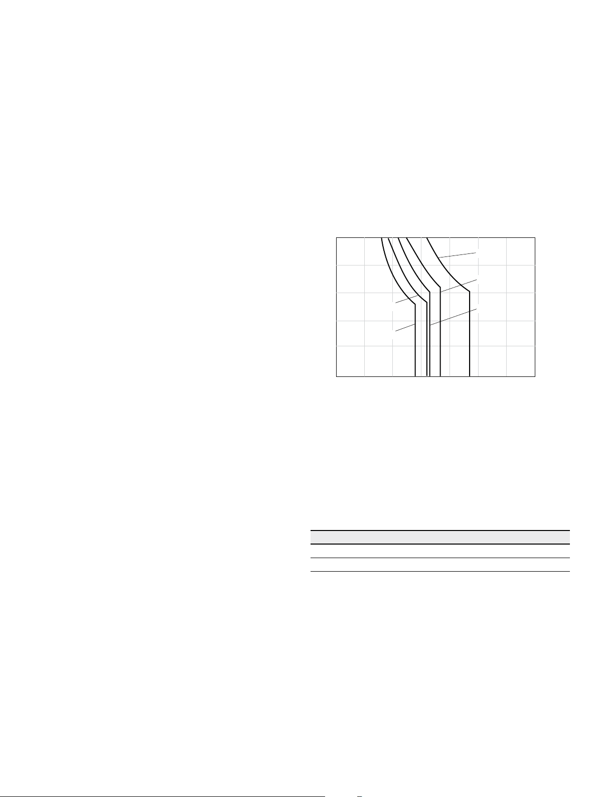
Details regarding the selection of hydraulic fluid
The hydraulic fluid should be selected such that the
operating viscosity in the operating temperature range is
within the optimum range (ν
, see selection diagram).
opt
Note
At no point of the component may the temperature be
higher than 115 °C. The temperature difference specified in
the table is to be taken into account when determining the
viscosity in the bearing.
If it is not possible to maintain the conditions above due to
extreme operating parameters, we recommend flushing the
case at port U.
between axial piston unit and hydraulic fluid in the system
, n≤0.5×n
nom
This corresponds, for example on the VG46, to a temperature
range of +5°C to +85 °C (see selection diagram)
measured at port R
Note the permissible temperature range of the shaft seal
(ΔT=approx.12K between the bearing/shaft seal and port R
Range of optimum operating viscosity and efficiency
1/R2
nom
and t≤15min
nom
1/R2
)
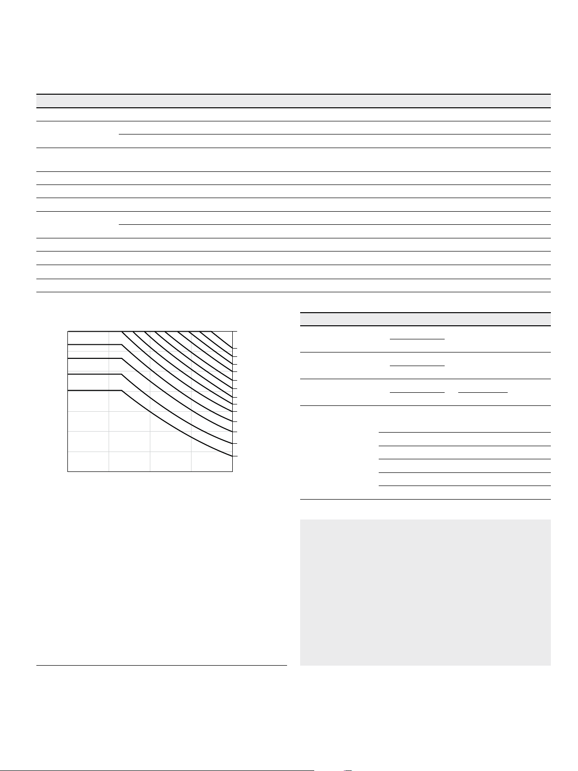
▼ Selection diagram
Maximum permissible viscosity for cold start
Range of optimum operating viscosity v
Optimum efficiency
Minimum permissible viscosity for short-term operation
Minimum permissible temperature for cold start
opt
1600
1000
600
400
200
100
Continuous operation
Warm-up phase
VG 100
VG 22
60
40
36
20
16
10
7
-40 -25 -10 10 30 50 90 11570
VG 68
VG 46
VG 32
0
Temperature θ [°C]
/s]
2
Viscosity v [mm
Bosch Rexroth AG, RE 92202/02.2015
Axial piston variable pump | A7VO Series 63
Shaft seal ring
5
Filtration of the hydraulic fluid
Finer filtration improves the cleanliness level of the hydraulic fluid, which in turn increases the service life of the axial
piston unit.
A cleanliness level of at least 20/18/15 is to be maintained
according to ISO 4406.
At very high hydraulic fluid temperatures (90°C to maximum 103°C, measured at portR
) a cleanliness level is
1/R2
necessary of at least 19/17/14 according to ISO 4406.
Leakage
The case interior is connected to the suction chamber. A
separate case drain line from the case to the reservoir is
therefore not required (both R ports are plugged).
Exception: For versions with pressure controller or pressure
cut-off, a drain line is needed to relieve port T
to the
1
reservoir.
Shaft seal ring
Permissible pressure loading
The service life of the shaft seal is influenced by the speed
of the axial piston unit and the leakage pressure in the
housing (case pressure). Momentary pressure spikes
(t<0.1s) up to 10bar are allowed. The service life of the
shaft seal decreases with increasing frequency of pressure
spikes and increasing mean differential pressure.
The case pressure must be equal to or higher than the
ambient pressure.
5
NG28
4
NG55
3
2
1
Differential pressure ∆p [bar]
NG107
NG160
NG80
0
20000 4000 6000
Rotational speed n [rpm]
The FKM shaft seal ring may be used for leakage
temperatures from -25°C to +115°C. For application cases
below -25 °C, an NBR shaft seal is required (permissible
temperature range: -40 °Cto+90°C).
Flow direction
Direction of rotation, viewed on drive shaft
clockwise counter-clockwise
S to B S to A
RE 92202/02.2015, Bosch Rexroth AG
6 A7VO Series 63 | Axial piston variable pump
Operating pressure range
Operating pressure range
Pressure at working port A or B (high-pressure side) Definition
Nominal pressure p
Maximum pressure p
nom
max
Single operating period 10s
Total operating period 300 h
Minimum pressure (high-pressure side) 10 bar absolute Minimum pressure on high-pressure side (A or B) required to
Rate of pressure change R
Amax
Pressure at suction port S (Inlet)
Minimum pressure p
Maximum pressure p
Smin
Smax
350 bar absolute The nominal pressure corresponds to the maximum design
pressure.
400 bar absolute The maximum pressure corresponds the maximum operating
pressure within the single operating period. The sum of the single
operating periods must not exceed the total operating period.
prevent damage to the axial piston unit.
16000bar/s Maximum permissible rate of pressure build-up and reduction
during a pressure change over the entire pressure range.
0.8 bar absolute
2bar absolute
Minimum pressure at suction port S (inlet) that is required to avoid
damage to the axial piston unit. The minimum required pressure is
dependent on the speed and displacement of the axial piston unit
(see diagram on page 7).
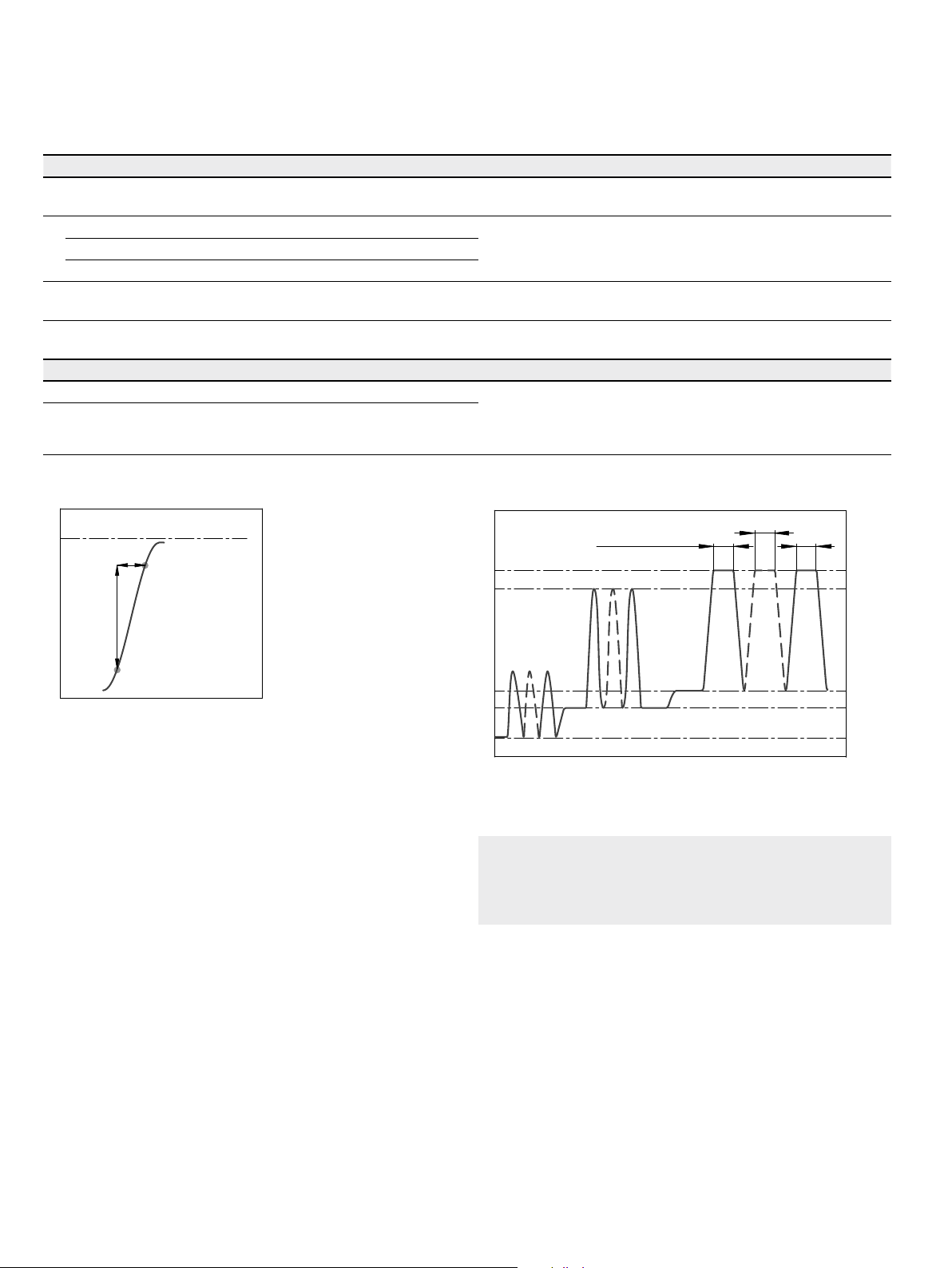
▼ Rate of pressure change R
p
nom
∆t
∆p
Pressure p
Time t
Amax
▼ Pressure definition
t
Single operating period
Maximum pressure p
Nominal pressure p
max
nom
2
t
1
t
n
Pressure p
Minimum pressure (high pressure side)
Time t
Total operating period = t1 + t2 + ... + t
n
Note
Operating pressure range valid when using hydraulic
fluids based on mineral oils. Values for other hydraulic
fluids, please contact us.
Bosch Rexroth AG, RE 92202/02.2015
Axial piston variable pump | A7VO Series 63
Technical data
Technical data
Size NG 28 55 80 107 160
Displacement, geometric, per revolution
Maximum rotational
1)
speed
At V
At V
g max
< 0.74 × V
g
Maximum rotational
2)
speed
Flow
Power
Torque
Rotary stiffness
At V
At V
At V
V
V
and n
g max
g max
g max
to Vg /2 c
g max
/2 to 0 (interpolated) c
g
nom
, n
and Δp=350bar P
nom
and Δp = 350 bar T
Moment of inertia rotary group
Maximum angular acceleration
Case volume
Weight (approx.)
g max
V
n
n
n
q
J
α
V
m
g max
nom
max1
max2
v
min
max
GR
3
cm
28.1 54.8 80 107 160
rpm 3150 2500 2240 2150 1900
rpm 4250 3400 3000 2900 2560
rpm 4750 3750 3350 3200 2850
l/min 89 137 179 230 304
kW 52 80 105 134 177
Nm 156 305 446 596 891
kNm/rad 5 10 16 21 36
kNm/rad 16 32 49 67 104
kgm² 0.0042 0.0042 0.0080 0.0127 0.0253
rad/s² 35900 31600 24200 19200 15300
l 0.5 0.75 1.2 1.5 2.4
kg 17 25
40 49 71
7
▼ Maximum permissible speed (limit speed)
Speed n / n
1.5
1.4
1.3
nom
1.2
1.1
1.0
2.3
2.0
1.9
1.8
1.7
1.6
1.5
1.4
1.3
1.2
1.1
1.0
0.9
0.9
0.8
0.6 0.7 0.8 0.9 1.0
Displacement Vg / V
1) The values are valid:
‒ At absolute pressure p
= 1bar at suction port S
abs
‒ For the optimal viscosity range of ν
g max
=36 to 16 mm2/s
opt
0.8
‒ For hydraulic fluid based on mineral oils.
2) Maximum rotational speed (speed limit) for increased inlet
pressure p
at suction port S and Vg < V
abs
, see diagram.
g max
Determining operating characteristics
× n × η
V
g
1000
× Δp
V
g
60000
v
[l/min]
[Nm]
mh
q
× Δp
v
=
600 × η
[kW]
t
abs
Flow
Torque
Power
q
T
P
v
=
=
=
20 × π × η
2 π × T × n
Key
V
Inlet pressure p
g
Δp
n
η
v
η
mh
η
t
= Displacement per revolution [cm3]
= Differential pressure [bar]
= Rotational speed [rpm]
= Volumetric efficiency
= Mechanical-hydraulic efficiency
=
Total efficiency (η
= ηv × ηmh)
t
Notes
▶ Theoretical values, without efficiency and tolerances;
values rounded
▶ Operation above the maximum values or below the
minimum values may result in a loss of function, a
reduced service life or in the destruction of the axial
piston unit. Other permissible limit values, such as
speed variation, reduced angular acceleration as a
function of the frequency and the permissible angular
acceleration at start (lower than the maximum angular
acceleration) can be found in data sheet 90261.
RE 92202/02.2015, Bosch Rexroth AG
8 A7VO Series 63 | Axial piston variable pump
Technical data
Permissible radial and axial forces of the drive shaft
Size NG 28 55 80 107 160
Drive shaft Ø mm 25 30 35 40 45
Maximum radial force
at distance a (from shaft
collar)
Maximum torque at F
Maximum differential pressure at V
F
qmax
Maximum axial force at
standstill or pressurefree operation
Permissible axial force per bar operating pressure
1)
q max
F
q
a
and
g max
+
F
ax
–
F
q max
a mm 14.0 17.5 20.0 22.5 25.0
T
q max
Δp
q max
+F
axmax
−F
axmax
+F
axperm
N 6436 7581 10266
Nm 179 281 444 681 1019
bar 400 322 349 400 400
N 0 0 0 0 0
N 315 500 710 900 11250
/bar
N/bar
4.6 7.5 9.6 11.3 15.1
13758
18278
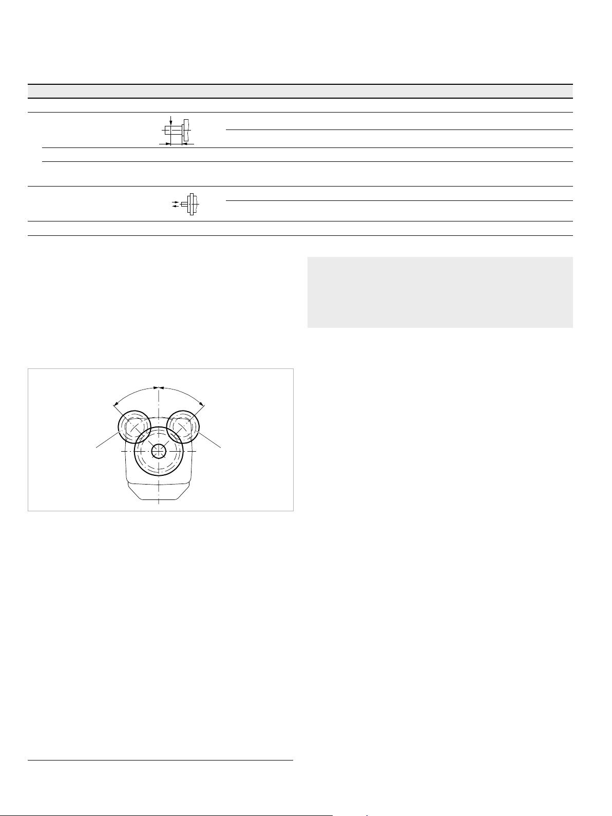
Effect of radialforce Fq on the service life of bearings
By selecting a suitable direction of radial force F
, the load
q
on the bearings, caused by the internal rotary group forces
can be reduced, thus optimizing the service life of the
bearings. Recommended position of mating gear is dependent on direction of rotation. Example:
▼ Gear drive
φ
°
5
4
=
t
p
o
φ
1 “Clockwise” rotation, pressure at port B
2 “Counter-clockwise” rotation, pressure at port A
o
p
t
=
4
5
°
21
Note
▶ The permissible axial force in direction −F
is to be
ax
avoided, because thereby the bearing life is reduced.
▶ Special requirements apply in the case of belt drives.
Please contact us.
1) With intermittent operation
Bosch Rexroth AG, RE 92202/02.2015
Axial piston variable pump | A7VO Series 63
LR – Power controller without power override
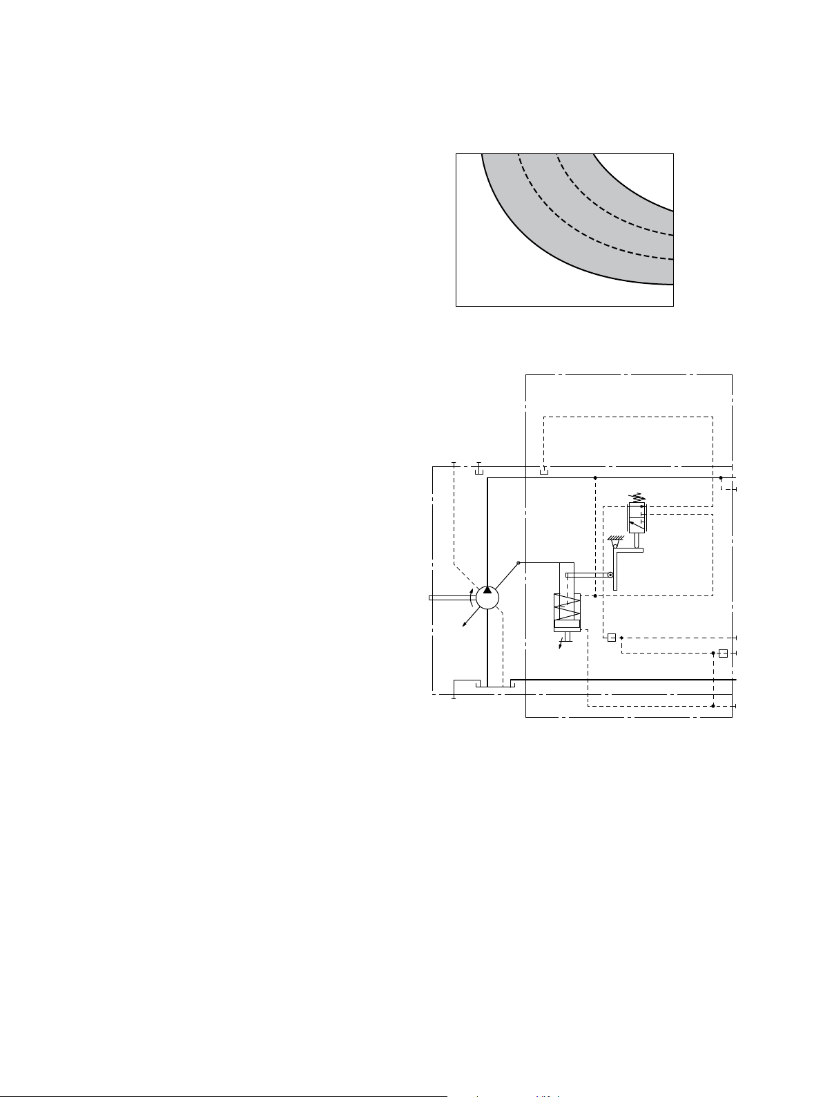
LR – Power controller without power override
9
The power controller regulates the displacement of the
pump depending on the operating pressure so that a given
drive power is not exceeded at constant drive speed.
The precise control with a hyperbolic control characteristic,
provides an optimum utilization of available power.
The operating pressure acts on a rocker via a measuring
spool which moves with the control. An externally adjustable spring force counteracts this, it determines the power
setting.
If the operating pressure exceeds the set spring force, the
control valve is actuated by the rocker and the pump swivels back from the initial position V
gmax
toward V
gmin
. When
doing this, the lever length at the rocker shortens and the
operating pressure may rise in the same proportion as the
displacement reduces without the drive power being
exceeded (p
=displacement).
V
g
×Vg=constant; pB=operating pressure;
B
When depressurized, the pump is swiveled to its initial
position to V
by a return spring.
g max
The hydraulic output power (characteristic LR) is influenced by the efficiency of the pump.
▶ Beginning of control, setting range 50 to 220bar
When ordering, state in plain text:
▶ Drive power P [kW]
▶ Drive speed n [rpm]
▶ Maximum flow q
v max
[l/min]
Please contact us if you need a power diagram.
▼ Characteristic curve LR
[bar]
B
Operating pressure p
V
displacement V
g min
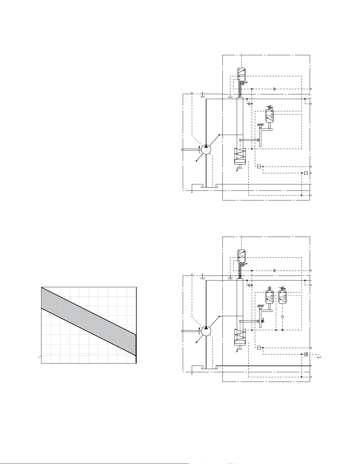
▼ Schematic LR
U
R
1
V
g min
V
g max
R
2
g max
220 bar
50 bar
B(A)
A
1
X
3
T
1
S
M
1
RE 92202/02.2015, Bosch Rexroth AG
10 A7VO Series 63 | Axial piston variable pump
LR – Power controller without power override
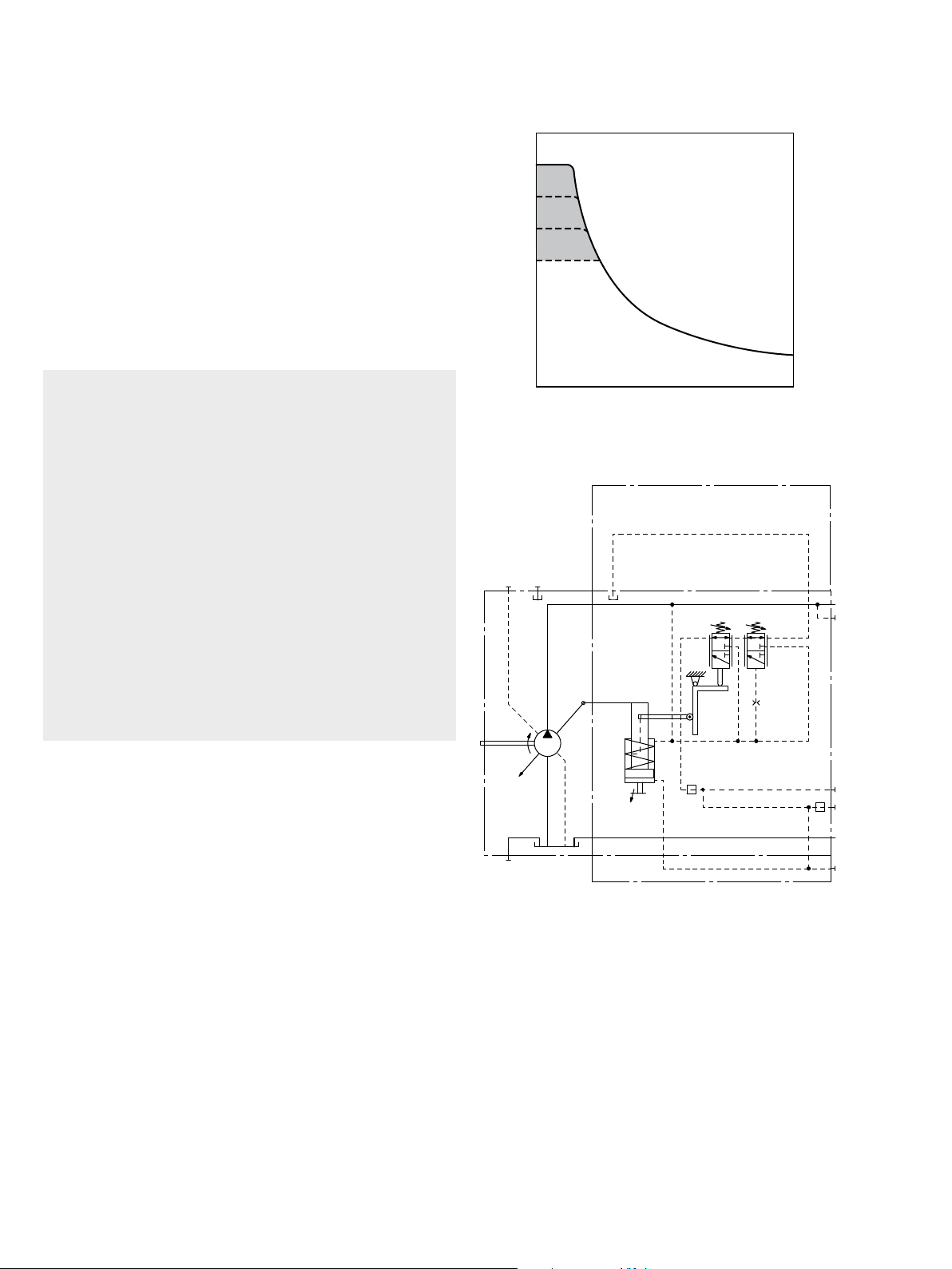
LRD – Power controller with pressure cut-off
The pressure cut-off is a pressure control which adjusts the
displacement of the pump back to V
after reaching the
g min
set pressure command value.
This function overrides the power controller, i.e. the power
control function is executed below the pressure command
value.
Pressure cut-off is preset to a pressure command value at
the factory.
▶ Setting range 200 to 350 bar
When ordering, state the setting in plain text.
Notes
▶ The pressure setting of the pressure cut-off must be at
least a factor of 5 higher than the beginning of control
of power control.
Example:
– Beginning of control of the power controller: 50bar
– Minimum setting of pressure cut-off:
5×50=250bar
Higher settings of the pressure cut-off are always
possible.
▶ For versions with pressure cut-off, a drain line is
needed from port T
When port T
1
to the reservoir.
1
is plugged and t
≤50°C, this results
tank
in a permissible pressure cut-off of≤2 min.
▶ Any pressure-relief valve included in the system to limit
the maximum pressure must have its start of opening
at least 20 bar above the pressure cut-off setting.
▼ Characteristic curve LRD
max
350
[bar]
B
200
min
Operating pressure p
V
displacement V
g min
▼ Schematic LRD
U
R
1
V
g min
V
g max
g max
B(A)
A
1
X
3
Bosch Rexroth AG, RE 92202/02.2015
T
1
S
R
2
M
1
Axial piston variable pump | A7VO Series 63
LR – Power controller without power override
11
LR… – Power controller with stroke limiter
Due to the hydraulic stroke limiter, it is possible to change
or limit the displacement of the pump continuously across
the entire control range. The displacement is set proportionally using the pilot pressure p
applied to port X1
St
(maximum of 40 bar).
The power control overrides the hydraulic stroke limiter, i.e.
below the power characteristic (hyperbolic characteristic),
the displacement is controlled in dependence on the pilot
pressure. If the set flow or operating pressure exceeds the
power control characteristic, the power control overrides
and reduces the displacement along the hyperbolic characteristic.
A control pressure of 40bar is needed to swivel the pump
from its initial position V
gmax
to V
gmin
.
The necessary control power is taken from the operating
pressure or the external control pressure applied to port Y
3
To ensure that the stroke limiter functions at a low operating pressure of <40bar, port Y
must be supplied with an
3
external control pressure of about 40bar.
LRH1 – Hydraulic stroke limiter (negative control)
▶ Control from V
gmax
to V
gmin
As the pilot pressure increases, the pump swivels to a
smaller displacement.
▶ Start of control (at V
) can be set to 4to15bar
gmax
When ordering, state the start of control in plain text.
▶ Initial position without pilot signal (pilot pressure): V
gmax
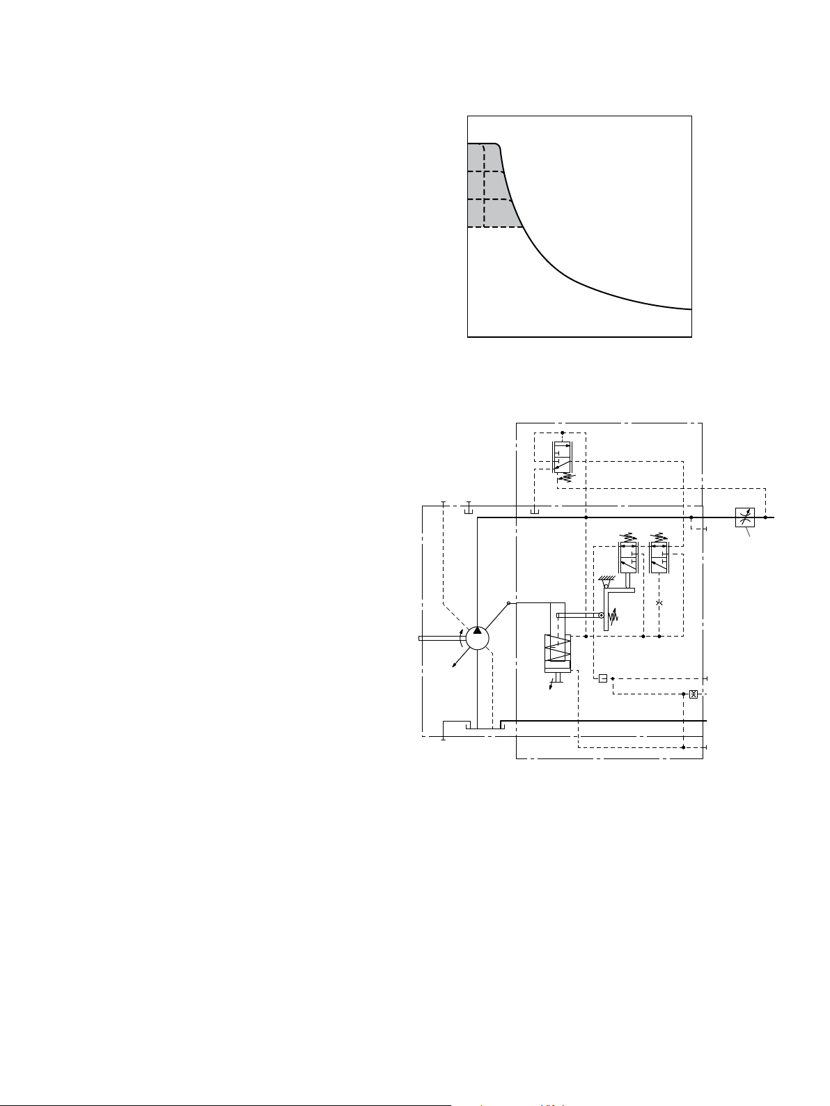
▼ Schematic LRH1
U
.
R
2
▼ Schematic LRDH1
X
1
Y
R
1
3
B(A)
A
1
V
g min
V
g max
X
3
T
1
S
M
1
X
1
▼ Characteristic curve LRH1
control pressure increase (V
40
35
30
[bar]
St
25
20
15
10
Pilot pressure p
5
4
0 0.6 0.8 1.00.40.2
Displacement Vg/V
gmax
–V
g max
) Δp=25bar
gmin
Y
U
R
1
3
B(A)
A
1
V
g min
V
g max
X
3
T
1
S
R
2
M
1
RE 92202/02.2015, Bosch Rexroth AG
12 A7VO Series 63 | Axial piston variable pump
LR – Power controller without power override
LRDS – Power control with pressure cut-off and load
sensing
The load sensing controller works as a load-pressure controlled flow controller and adjusts the displacement of the
pump to the volume required by the consumer. The flow of
the pump is then dependent on the cross section of the
external measuring orifice (1), which is located between
the pump and the consumer. Below the power curve and
the setting of the pressure cut-off and within the control
range of the pump, the flow is independent of the load
pressure.
The measuring orifice is usually a separately located load
sensing directional valve (control block). The position of
the directional valve spool determines the opening crosssection of the measuring orifice and thus the flow of the
pump.
The load sensing controller compares pressure before and
after the orifice and keeps the pressure drop (differential
pressure Δp) across the orifice – and therefore the
flow – constant.
If the differential pressure ∆p at the measuring orifice rises,
the pump is swiveled back (toward V
). If the differential
g min
pressure Δp drops, the pump is swiveled out (toward
) until equilibrium at the measuring orifice is restored.
V
gmax
Δp
measuring orifice
=p
pump
–p
consumer
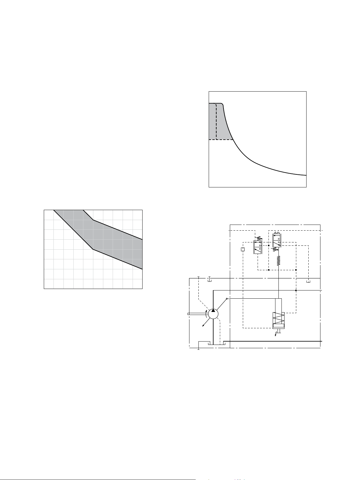
▼ Characteristic curve LRDS
max
350
[bar]
B
200
min
Operating pressure p
V
displacement V
g min
▼ Schematic LRDS
U
R
1
g max
X
4
B(A)
A
1
1
▶ Setting range for Δp 14to25bar
▶ Default setting 18bar
When ordering, state the setting in plain text.
The stand-by pressure in zero-stroke mode (metering orifice
closed) is slightly higher than the Δp setting.
In an LUDV system, the pressure cut-off is integrated in the
flow sharing control block (LUDV).
V
g min
V
g max
R
2
X
3
T
1
S
M
1
The measuring orifice (control block) (1) is not included in
the scope of delivery.
Bosch Rexroth AG, RE 92202/02.2015
Axial piston variable pump | A7VO Series 63
LA1 – Power controller with hydraulically proportional power override
LA1 – Power controller with hydraulically proportional power override
13
The power controller regulates the displacement of the
pump depending on the operating pressure so that a given
drive power is not exceeded at constant drive speed.
The hyperbolic power curve is approximated with two
measuring springs. The operating pressure acts on the measurement area of a differential piston against the measuring
springs and an externally adjustable spring force which
determines the power setting.
If the sum of the hydraulic forces exceeds the forces of the
springs, the control oil is fed to the stroking piston, which
swivels the pump back to reduce the flow.
In a depressurized state, the pump is swiveled to its initial
position to V
By connecting an external pilot pressure at port X
by a return spring.
g max
, it is
3
possible to override the power control proportionally.
Increasing pilot pressure=reduced power.
▼ Characteristic curve LA1
400
350
[bar]
300
A
250
200
150
100
Operating pressure p
50
0
0 0.2 0.4 0.6 0.8 1.0
V
displacement V
g min
Setting range
Beginning of control
g max
LA1S – Power controller with load sensing
For description of load sensing, see page12.
▼ Characteristic curve LA1S
max
350
[bar]
B
200
min
Operating pressure p
V
displacement V
g min
▼ Schematic LA1S
X
4
U
R
1
g max
X
3
A
V
The hydraulic output power (characteristic curve) is
affected by the efficiency.
V
g min
g max
When ordering, state in plain text:
▶ Drive power P [kW]
▶ Drive speed n [rpm]
▶ Maximum volume flow q
V max
[l/min]
R
2
S
Please contact us if you need a power diagram.
RE 92202/02.2015, Bosch Rexroth AG
 Loading...