

Bosch Rexroth A6VM 71 User Manual
RE-A 91610/12.2015, Bosch Rexroth Corp.
Features
▶ Variable motor with axial tapered piston rotary group of
bent-axis design, for hydrostatic drives in open and
closed circuit
▶ For use in mobile and stationary applications
▶ The wide control range enables the variable motor to
satisfy the requirement for high speed and high torque.
▶ The displacement can be infinitely varied from V
gmax
to
V
gmin
=0.
▶ The output speed is dependent on the flow of the pump
and the displacement of the motor.
▶ The output torque increases with the pressure differen-
tial between the high and low-pressure side and with
increasing displacement.
▶ Wide control range with hydrostatic transmissions
▶ Wide selection of control devices
▶ Cost savings through elimination of gear shifts and
possibility of using smaller pumps
▶ Compact, robust motor with long service life
▶ High power density
▶ Good starting efficiency
▶ Version with 9-piston rotary group
▶ Good low speed characteristics
▶ High uniformity
▶ Sizes 60 to 215
▶ Nominal pressure 6500psi (450bar)
▶ Maximum pressure 7250psi (500bar)
▶ Open and closed circuits
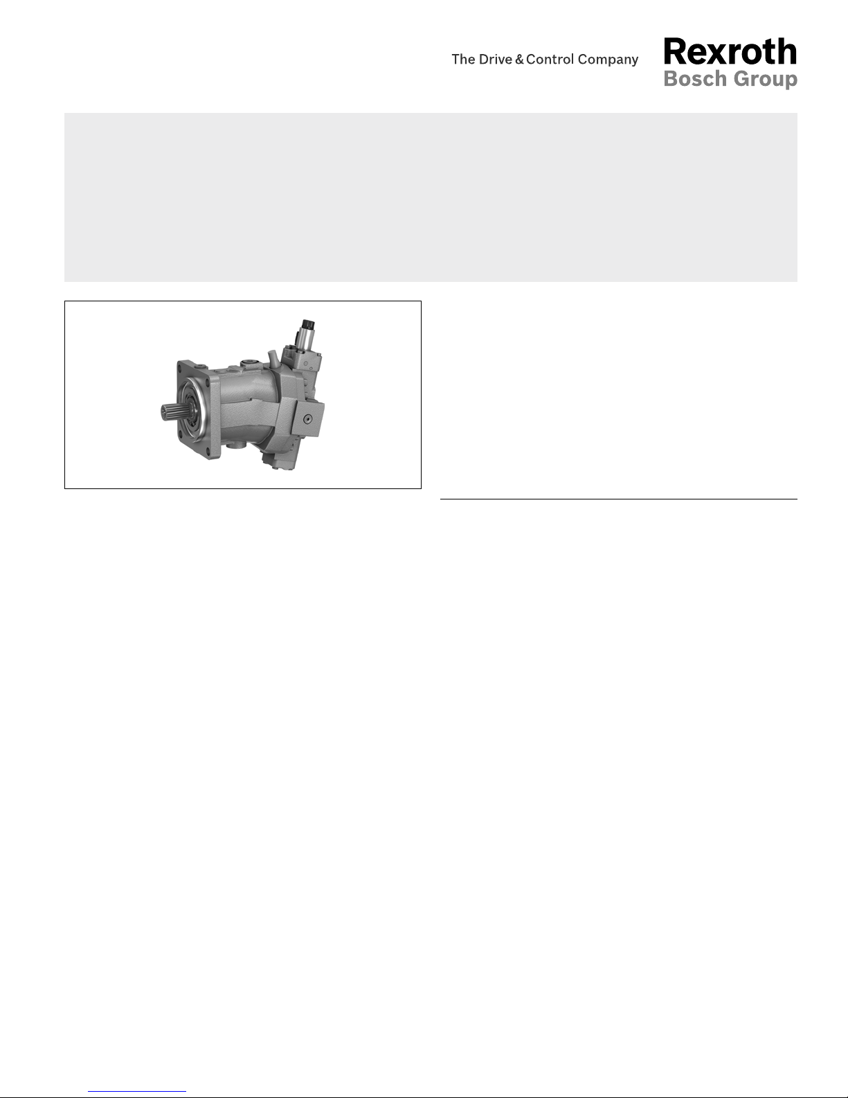
Axial piston variable motor
A6VM series 71
RE-A 91610
Edition: 12.2015
Replaces: 04.2013
Contents
Type code 2
Hydraulic fluids 5
Flow direction 6
Shaft seal 6
Operating pressure range 7
Technical data 8
HP – Proportional hydraulic control 10
EP – Proportional electric control 13
HZ – Two-point hydraulic control 15
EZ – Two-point electric control 16
HA – Automatic high-pressure related control 17
DA – Automatic speed-related control 22
Electric travel direction valve (for DA, HA.R) 24
Dimensions size 60 25
Dimensions size 85 31
Dimensions size 85 32
Dimensions size 115 38
Dimensions size 150 44
Dimensions size 170 50
Dimensions size 215 56
Connector for solenoids 62
Flushing and boost pressure valve 63
Counterbalance valve BVD and BVE 65
Speed sensor 69
Setting range for displacement 70
Installation instructions 72
Project planning notes 74
Safety instructions 75
Americas
Bosch Rexroth Corp., RE-A 91610/12.2015
2 A6VM series 71 | Axial piston variable motor
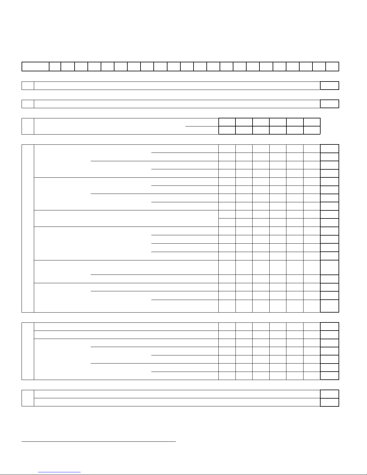
Type code
Type code
01 02 03 04 05 06 07 08 09 10 11 12 13 14 15 16 17 18 19 20 21
A6V M 0 0 / 71 A W V 0 –
Axial piston unit
01 Bent-axis design, variable, nominal pressure 6500psi (450bar), maximum pressure 7250psi (500bar)
A6V
Operating mode
02 Motor M
Size (NG)
03 Geometric displacement, see technical data on page 8 in cm
3
/rev
060 085 115 150 170 215
in in
3
/rev
3.66 5.19 7.02 9.15 10.37 13.12
Control device 060 085 115 150 170 215
04 Proportional control
hydraulic
positive control
Δp
St
=145psi (10bar)
● ● ● ● ● ● HP1
Δp
St
=365psi (25bar)
● ● ● ● ● ● HP2
negative control
Δp
St
=145psi (10bar)
● ● ● ● ● ● HP5
Δp
St
=365psi (25bar)
● ● ● ● ● ● HP6
Proportional control
electrical
positive control
U = 12 V DC
● ● ● ● ● ● EP1
U = 24 V DC
● ● ● ● ● ● EP2
negative control
U = 12 V DC
● ● ● ● ● ● EP5
U = 24 V DC
● ● ● ● ● ● EP6
Two-point control
hydraulic
negative control
‒ ‒ ‒ ● ● ● HZ5
● ● ● ‒ ‒ ‒ HZ7
Two-point control
electrical
negative control
U = 12 V DC
‒ ‒ ‒ ● ● ● EZ5
U = 24 V DC
‒ ‒ ‒ ● ● ● EZ6
U = 12 V DC
● ● ● ‒ ‒ ‒ EZ7
U = 24 V DC
● ● ● ‒ ‒ ‒ EZ8
Automatic control
high-pressure related,
Positive control
with minimum pressure
increase
Δp≤approx.145psi (10bar)
● ● ● ● ● ● HA1
with pressure increase
Δp=1450psi (100bar)
● ● ● ● ● ● HA2
Automatic control
speed related, negative
control p
St
/ pHD=5/100
hydr. travel direction valve ● ● ● ● ● ● DA0
electric travel direction
valve + electric V
gmax
circuit
U = 12 V DC
● ● ● ● ● ● DA1
U = 24 V DC
● ● ● ● ● ● DA2
Pressure control/override 060 085 115 150 170 215
05 Without pressure control/override
● ● ● ● ● ● 00
Pressure control fixed setting, only for HP5, HP6, EP5 and EP6
● ● ● ● ● ● D1
Override
of controls
HA1 and HA2
hydraulic remote control, proportional
● ● ● ● ● ● T3
electric, two-point
U = 12 V DC
● ● ● ● ● ● U1
U = 24 V DC
● ● ● ● ● ● U2
electric and travel
direction valve, electric
U = 12 V DC
● ● ● ● ● ● R1
U = 24 V DC
● ● ● ● ● ● R2
Connector for solenoids
1)
(see page 62)
06 Without connector (without solenoid, only for hydraulic control)
0
DEUTSCH - molded connector, 2-pin, without suppressor diode
P
●
= Available
○
= On request
‒
= Not available
1) Connectors for other electric components can deviate.
RE-A 91610/12.2015, Bosch Rexroth Corp.
Axial piston variable motor | A6VM series 71
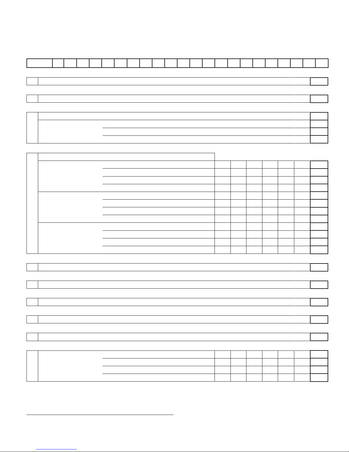
Type code
3
01 02 03 04 05 06 07 08 09 10 11 12 13 14 15 16 17 18 19 20 21
A6V M 0 0 / 71 A W V 0 –
2) The settings for the setting screws can be found in the table
(seepages 70 and 71).
Additional function 1
07 Without additional function
0
Additional function 2
08 Without additional function
0
Response time damping (for selection, see control)
09 Without damping (standard with HP and EP)
0
Damping HP, EP, HP5,6D. and EP5,6D., HZ, EZ, HA with counterbalance valve BVD/BVE
1
One-sided in inlet to large stroking chamber (HA)
4
One-sided in outlet from large stroking chamber (DA)
7
Setting range for displacement
2)
10
V
g max
-setting screw
V
g min
-setting screw 060 085 115 150 170 215
Without setting screw
short (0-adjustable)
● ● ● ● ● ● A
medium
● ● ● ● ● ● B
long
● ● ● ● ● ● C
extra long
‒ ● ● ● ● ● D
Short
short (0-adjustable)
● ● ● ● ● ● E
medium
● ● ● ● ● ● F
long
● ● ● ● ● ● G
extra long
‒ ● ● ● ● ● H
Medium
short (0-adjustable)
● ● ● ● ● ● J
medium
● ● ● ● ● ● K
long
● ● ● ● ● ● L
extra long
‒ ● ● ● ● ● M
Series
11 Series 7, index 1
71
Configuration of ports and fastening threads
12 ANSI, port threads with O-ring sealing according to ISO 11926
A
Direction of rotation
13 Viewed on drive shaft, bidirectional
W
Sealing material
14 FKM (fluoroelastomer)
V
Drive shaft bearing
15 Standard bearing
0
Mounting flange 060 085 115 150 170 215
16 SAE J744 127-4
● ● ‒ ‒ ‒ ‒ C4
127-2
‒ ● ‒ ‒ ‒ ‒ C2
152-4
‒ ‒ ● ● ● ‒ D4
165-4
‒ ‒ ‒ ‒ ‒ ● E4
●
= Available
○
= On request
‒
= Not available

Bosch Rexroth Corp., RE-A 91610/12.2015
4 A6VM series 71 | Axial piston variable motor
Type code
3)
Only possible in conjunction with HP, EP and HA control. Note the
restrictions described on page 65.
4) State ordering code for counterbalance valve separately in accor-
dance with data sheet 95522forBVD or 95525for BVE. Note the
restrictions described on page 65.
5) Not for EZ7, EZ8 and HZ7.
6) State ordering code for sensor separately in accordance with data
sheet 95132forDSM or 95133forDSA and note the requirements
relating to the electronics.
01 02 03 04 05 06 07 08 09 10 11 12 13 14 15 16 17 18 19 20 21
A6V M 0 0 / 71 A W V 0 –
Drive shaft 060 085 115 150 170 215
17
Splined shaft
ANSI B92.1a
1 1/4 in 14T 12/24 DP
● ‒ ‒ ‒ ‒ ‒ S7
1 1/2 in 17T 12/24 DP
‒ ● ‒ ‒ ‒ S9
1 3/4 in 13T 8/16 DP
‒ ‒ ● ● ‒ ‒ T1
2 in 15T 8/16 DP
‒ ‒ ‒ ○ ● ● T2
Port plate for working ports 060 085 115 150 170 215
18
SAE working ports A and B at rear
● ● ● ● ● ● 1
SAE working ports A and B at side, opposite
● ● ● ● ● ● 2
Port plate with 1-stage pressure limitation
valves for mounting a counterbalance valve
3)
BVD20
● ● ● ‒ ‒ ‒ 7
BVD25, BVE25
‒ ‒ ● ● ● ● 8
Valve (see pages 63 to 68) 060 085 115 150 170 215
19 Without valve
● ● ● ● ● ● 0
With counterbalance valve BVD/BVE mounted
4)
● ● ● ● ● ● W
With flushing and boost pressure valve, mounted
Flushing on both sides
Flushing flow at:
Δp=p
ND
‒pG=365psi (25bar) and
ν=60SUS (10 mm
2
/s)
(p
ND
=low pressure, p
G
=case pressure)
Only possible with port plates 1 and 2
Flushing flow q
v
[gpm (l/min)]
0.9 (3.5)
● ● ● ‒ ‒ ‒ A
1.3 (5)
● ● ● ‒ ‒ ‒ B
2.1 (8)
● ● ● ● ● ● C
2.6 (10)
● ● ● ● ● ● D
3.7 (14)
● ● ● ‒ ‒ ‒ F
4.0 (15)
‒ ‒ ●
5)
● ● ● G
4.8 (18)
‒ ‒ ●
5)
● ● ● I
5.5 (21)
‒ ‒ ●
5)
● ● ● J
7.1 (27)
‒ ‒ ●
5)
● ● ● K
8.2 (31)
‒ ‒ ●
5)
● ● ● L
9.7 (37)
‒ ‒ ‒ ● ● ● M
Speed sensor (see page 69)
060 085 115 150 170 215
20 Without speed sensor
● ● ● ● ● ● 0
Prepared for speed sensor DSM/DSA
● ● ● ● ● ● U
With speed sensor DSM/DSA mounted
6)
● ● ● ● ● ● V
Standard / special version
21
Standard version
0
Standard version with installation variants, e. g. T ports against standard open and closed
Y
Special version
S
●
= Available
○
= On request
‒
= Not available
Notes
▶ Note the project planning notes on page 74.
▶ When ordering, please provide the relevant technical
data additionally to the type code
RE-A 91610/12.2015, Bosch Rexroth Corp.
Axial piston variable motor | A6VM series 71
Hydraulic fluids
5
Hydraulic fluids
The variable motor A6VM is designed for operation with
mineral oil HLP according to DIN 51524.
Application instructions and requirements for hydraulic
fluids should be taken from the following data sheets
before the start of project planning:
▶ 90220: Hydraulic fluids based on mineral oils and
related hydrocarbons
▶ 90221: Environmentally acceptable hydraulic fluids
▶ 90222: Fire-resistant, water-free hydraulic fluids
(HFDR/HFDU)
▶ 90223: Fire-resistan, water-containing hydraulic fluids
(HFAE, HFAS, HFB, HFC)
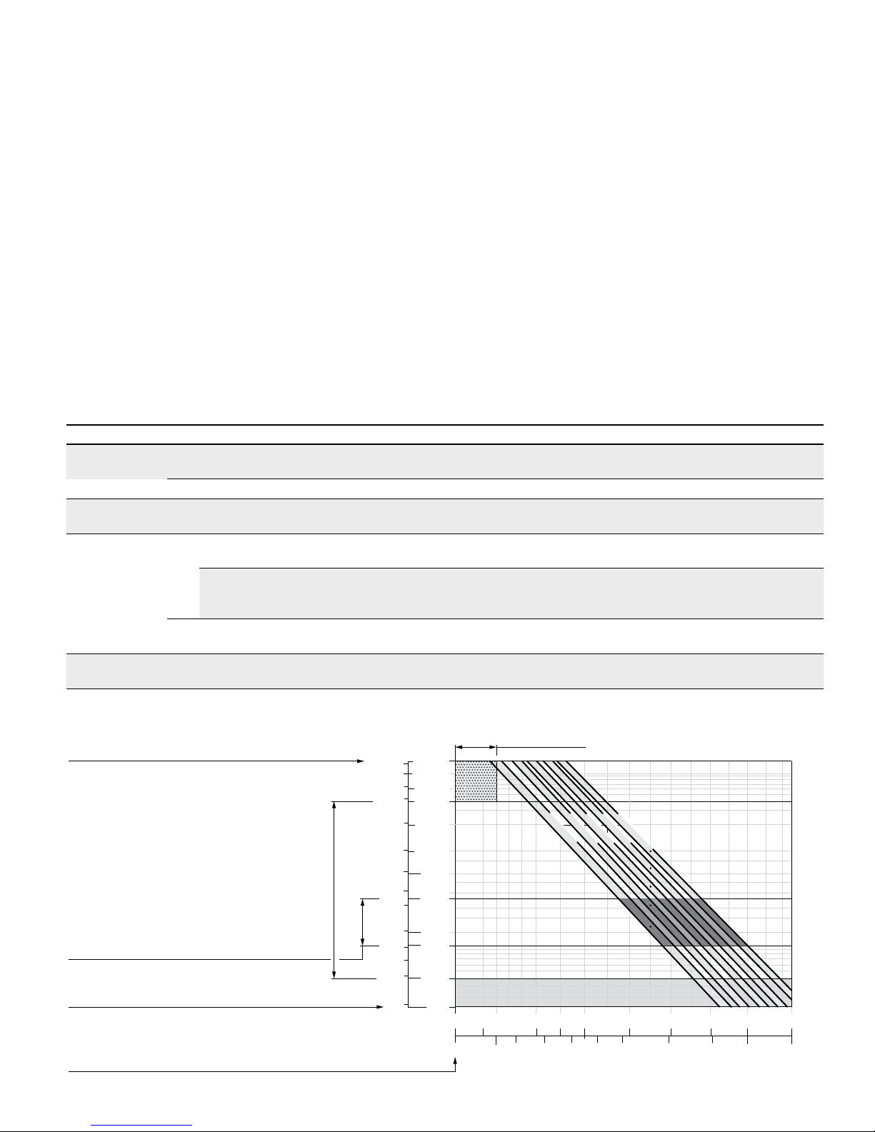
Details regarding the selection of hydraulic fluid
The hydraulic fluid should be selected such that the operating viscosity in the operating temperature range is within
the optimum range (ν
opt
see selection diagram).
Note
At no point of the component may the temperature be higher
than 240°F (115°C). The temperature difference specified
in the table is to be taken into account when determining the
viscosity in the bearing.
If the above conditions cannot be maintained due to extreme
operating parameters, we recommend flushing the case at port
U or using a flushing and boost pressure valve (see page 63).
Viscosity and temperature of hydraulic fluids
Viscosity Temperature Comment
Cold start
ν
max
≤
7400 SUS
(1600 mm
2
/s)
θ
St
≥
−40°F (−40°C)
t≤3 min, n≤1000 rpm, without load p≤725psi (p≤50bar)
Permissible temperature difference
ΔT≤
45°F (25K) between axial piston unit and hydraulic fluid in the system
Warm-up phase
ν<
7400 to 1850SUS
(1600to 400mm
2
/s)
θ=
−40°F to −13 °F
(−40°C to −25°C)
at p≤0.7×p
nom
, n≤0.5×n
nom
and t≤15min
Continuous
operation
ν =
1850 to 47SUS
(400 to 10mm
2
/s)
This corresponds, for example on the VG46, to a temperature range
of +41°F to + 185 °F (+5°C to +85 °C)(see selection diagram)
θ=
−13°Fto +217°F
(−25°Cto +103°C)
measured at port T
Note the permissible temperature range of the shaft seal
(ΔT=approx.22°F (12K) between the bearing/shaft seal and port T)
ν
opt
=
167 to 81 SUS
(36 to 16mm
2
/s)
Range of optimum operating viscosity and efficiency
Short-term
operation
ν
min
≥
49 SUS
(7mm
2
/s)
t<3min, p<0.3×p
nom
▼ Selection diagram
60
200
300
100
500
1000
2000
3000
5000
7000
VG 22
VG 32
VG 46
VG 68
VG 100
80
150
(7)
(10)
(40)
(60)
(20)
(100)
(200)
(400)
(600)
(1000)
(1600)
(16)
(36)
−40 −13 120
0 20 40 60 80 160 195
240
(−40)
(−25) (−10)
(0)
(10) (30) (50) (70) (90) (115)
50
70
Range of optimum operating viscosity ν
opt
Optimum efficiency
Maximum permissible viscosity for cold start
Minimum permissible viscosity
for short-term operation
Temperature θ [°F (°C)]
Viscosity ν [SUS (mm
2
/s)]
Continuous operation
Warm-up phase
Minimum permissible temperature for cold start
Bosch Rexroth Corp., RE-A 91610/12.2015
6 A6VM series 71 | Axial piston variable motor
Flow direction
Filtration of the hydraulic fluid
Finer filtration improves the cleanliness level of the hydraulic fluid, which increases the service life of the axial piston
unit.
A cleanliness level of at least 20/18/15 is to be maintained
according to ISO 4406.
At very high hydraulic fluid temperatures (195°F (90°C) to
maximum 217°F (103°C), measured at port T), a cleanliness level of at least 19/17/14 according to ISO 4406 is
necessary.
Influence of case pressure on beginning of control
An increase in case pressure affects the beginning of control when using the following control options:
▶ HP, HA.T3: Increase
▶ DA: Decrease
With the following settings, an increase in case pressure
will have no effect on the beginning of control:
HA.R and HA.U, EP, HA
The factory setting of the beginning of control is made at
p
abs
= 30psi (2bar) case pressure.
Flow direction
Direction of rotation, viewed on drive shaft
clockwise (cw) counter-clockwise (ccw)
A to B B to A
Shaft seal
Permissible pressure loading
The service life of the shaft seal will be influenced by the
speed of the axial piston unit and the leakage pressure in
the housing (case pressure). Momentary pressure spikes
(t<0.1s) of up to 145psi (10bar) are permitted. The
service life of the shaft seal decreases with increasing
frequency of pressure spikes and increasing mean differential pressure.
The case pressure must be equal to or higher than the
ambient pressure.
0
15 (1)
30 (2)
45 (3)
60 (4)
75 (5)
2000 4000 6000 8000 10000
NG170, 215
NG85
NG60
NG115, 150
NG170
NG60
NG85
NG115NG150
NG215
Differential pressure Δp [psi (bar)]
Rotational speed n [rpm]
The FKM shaft seal may be used for leakage temperatures
from -13°Fto+240°F(-25°Cto+115°C). For application
cases below -13°F(-25°C), an NBR shaft seal is required
(permissible temperature range:
-40°Fto+195°F(-40°Cto +90°C)).
RE-A 91610/12.2015, Bosch Rexroth Corp.
Axial piston variable motor | A6VM series 71
Operating pressure range
7
Operating pressure range
Pressure at working port A or B Definition
Nominal pressure p
nom
6500 psi (450bar) The nominal pressure corresponds to the maximum design pressure.
Maximum pressure p
max
7250psi (500bar) The maximum pressure corresponds to the maximum operating pres-
sure within the single operating period. The sum of the single operating
periods must not exceed the total operating period.
Single operating period 10s
Total operating period 300h
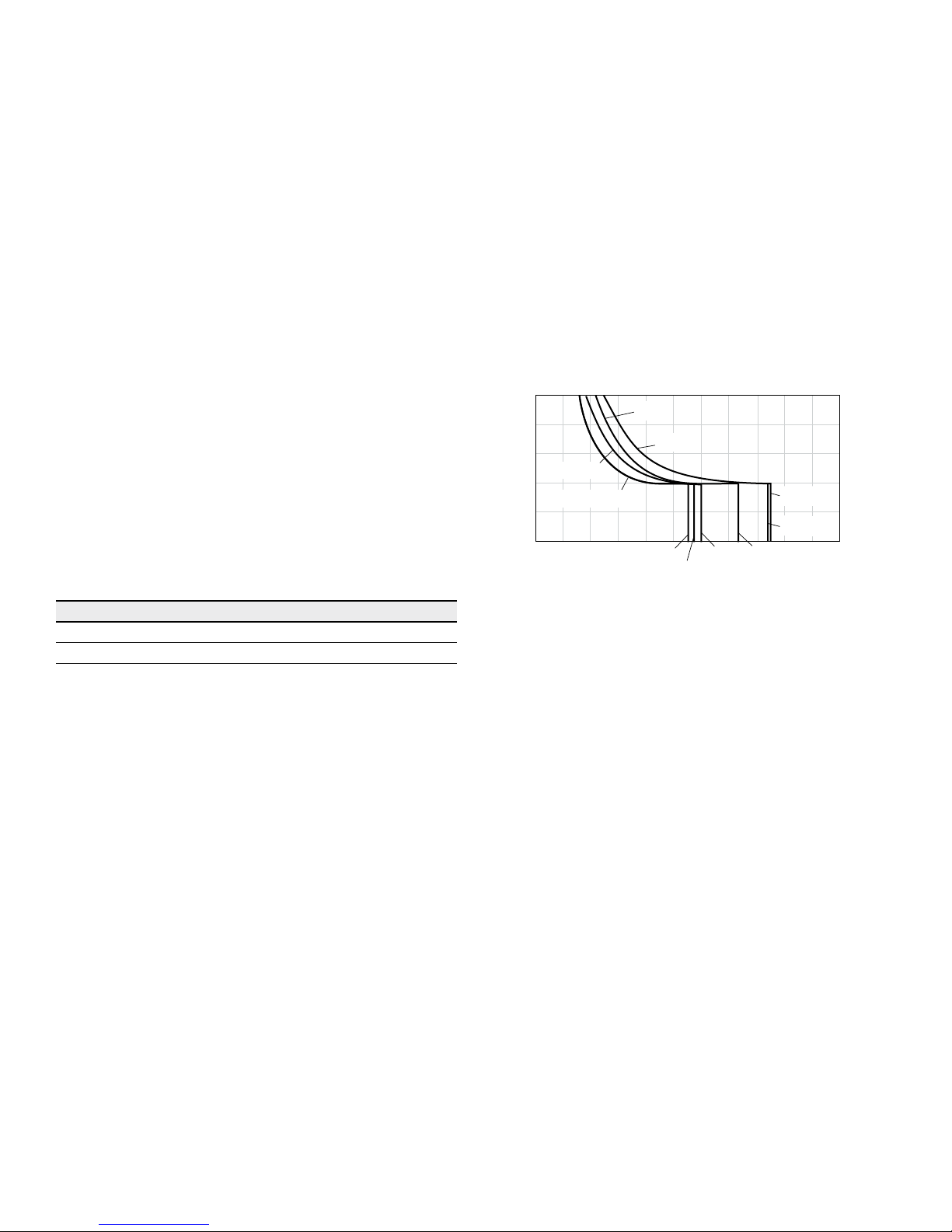
Minimum pressure
(high-pressure side)
365psi (25bar) Minimum pressure at the high-pressure side (A or B) which is required
in order to prevent damage to the axial piston unit.
Minimum pressure – pump operating
mode (inlet)
See the diagram below To prevent damage to the axial piston motor in pump operating mode
(change of high-pressure side with unchanged direction of rotation, e. g.
when braking), a minimum pressure must be guaranteed at workingport
(inlet). This minimum pressure is dependent on the speed and displacement of the axial piston unit (see characteristic curve)
Summation pressure p
Su
(pressure A + pressure B)
10150psi (700bar) The summation pressure is the sum of the pressures at both working
ports (A and B)
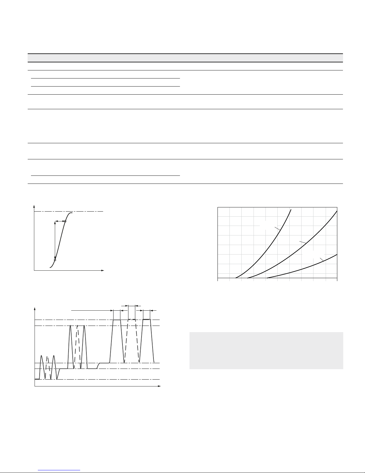
Rate of pressure change R
Amax
Maximum permissible rate of pressure build-up and reduction during a
pressure change over the entire pressure range.
With integrated pressure-relief valve 130530psi/s (9000bar/s)
Without pressure-relief valve 232060psi/s (16000bar/s)
▼ Rate of pressure change R
Amax
p
nom
∆t
∆p
Time t
Pressure p
▼ Pressure definition
Single operating period
Pressure p
t
1
t
2
t
n
Minimum pressure (high-pressure side)
Maximum pressure p
max
Nominal pressure p
nom
Time t
Total operating period = t1 + t2 + ... + t
n
▼ Minimum pressure – pump operating mode (inlet)
V
g max
V
g x
0.3 V
g max
15 (1)
30 (2)
60 (4)
90 (6)
115 (8)
145 (10)
175 (12)
200 (14)
230 (16)
0 0.4 0.7 1.0 1.3 1.6
Inlet pressure p
abs
[psi (bar)]
Rotational speed n / n
nom
This diagram is valid only for the optimum viscosity range
from
ν
opt
=170to73SUS (36 to 16mm2/s).
Please contact us if these conditions cannot be satisfied.
Note
Operating pressure range valid when using hydraulic
fluids based on mineral oils. Values for other hydraulic
fluids, please contact us.
Bosch Rexroth Corp., RE-A 91610/12.2015
8 A6VM series 71 | Axial piston variable motor
Technical data
Technical data
Size NG 60 85 115 160 170 215
Displacement geometric,
per revolution
V
g max
in
3
3.78 5.20 7.05 9.28 10.48 13.21
cm
3
62.0 85.2 115.6 152.1 171.8 216.5
V
g min
in
3
0 0 0 0 0 0
cm
3
0 0 0 0 0 0
V
g x
in
3
2.26 3.11 4.21 5.55 3.97 5.00
cm
3
37 51 69 91 65 82
Maximum speed
1)
(complying with the maximum
permissible inlet flow)
at V
g max
n
nom
rpm 4450 3900 3550 3250 3100 2900
at V
g
< V
g x
(see diagram) n
max
rpm 7200 6800 6150 5600 4900 4800
at V
g 0
n
max
rpm 8400 8350 7350 6000 5750 5500
Inlet flow
2)
at n
nom
and V
g max
q
v max
gpm 73 88 108 131 141 166
l/min 276 332 410 494 533 628
Torque
3)
at V
g max
and
Δp = 6500psi (450bar)
T
lb-ft 326 448 608 800 903 1139
Nm 444 610 828 1089 1230 1550
Rotary stiffness
V
g max
to Vg/2 c
min
lb-ft/rad 10695 16521 27511 32084 38279 51334
kNm/rad 14500 22400 37300 43500 51900 69600
V
g/2
to 0
(interpolated)
c
min
lb-ft/rad 33412 49785 76559 91458 115355 144267
kNm/rad 45300 67500 103800 124000 156400 195600
Moment of inertia for rotary group
J
TW
lb-ft
2
0.1020 0.1709 0.2610 0.4295 0.5055 0.7190
kgm
2
0.0043 0.0072 0.0110 0.0181 0.0213 0.0303
Maximum angular acceleration
α
rad/s² 21000 17500 15500 11000 11000 10000
Case volume
V
gal 0.21 0.26 0.40 0.45 0.61 0.74
l 0.8 1.0 1.5 1.7 2.3 2.8
Weight, approx.
m
lbs 62 79 101 134 137 172
kg 28 36 46 61 62 78
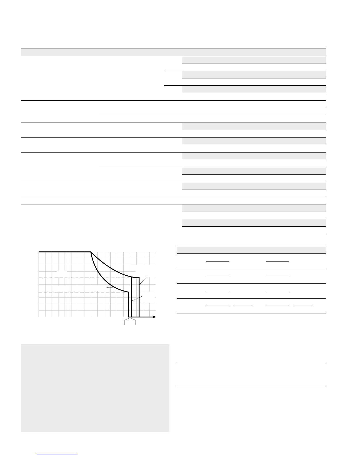
▼ Permissible displacement in relation to speed
NG170
NG85,
115, 150
1.58 1.62
NG60,
215
4)
1.0
0.8
0.63
0.4
0.38
0.2
0
V
g x
V
g x
0.2 0.4 0.6 0.8 1.0 1.2 1.4 1.74
Displacement V
g
/ V
g max
Rotational speed n / n
nom
Notes
▶ Theoretical values, without efficiency levels and toler-
ances; values rounded
▶ Operation above the maximum values or below the mini-
mum values may result in a loss of function, a reduced
service life or in the destruction of the axial piston unit.
Other permissible limit values, such as speed variation,
reduced angular acceleration as a function of the frequency and the permissible angular acceleration at start
(lower than the maximum angular acceleration) can be
found in data sheet 90261.
Determining the operating characteristics
Inlet flow
q
v
=
V
g
× n
[gpm]
(
Vg × n
)
[l/min]
231 × η
v
1000 × η
v
Rotational
speed
n
=
q
v
× 231 × η
v
[rpm]
(
qv × 1000 × η
v
)
[rpm]
V
g
V
g
Torque
T
=
V
g
× Δp × η
mh
[lb-ft]
(
Vg × Δp × η
mh
)
[Nm]
24 × π 20 × π
Power
P
=
2 π × T × n
=
qv × Δp × η
t
[HP]
(
2 π × T × n
=
qv × Δp × η
t
)
[kW]
33000
1714
60000
600
Key
V
g
= Displacement per revolution [in3 (cm3)]
Δp
= Differential pressure [psi (bar)]
n
= Rotational speed [rpm]
η
v
= Volumetric efficiency
η
mh
= Mechanical-hydraulic efficiency
η
t
=
Total efficiency (ηt = ηv • ηmh)
1) The values are valid:
– For the optimum viscosity range from ν
opt
= 170to75SUS
(36to 16mm
2
/s)
– with hydraulic fluid on the basis of mineral oil
2)
Note inlet flow limitation due to counterbalance valve (see page65).
3) Torque without radial force, With radial force see page 9.
4) Values in this range on request
RE-A 91610/12.2015, Bosch Rexroth Corp.
Axial piston variable motor | A6VM series 71
Technical data
9
Permissible radial and axial forces of the drive shafts
Size NG 60 85 115 150 150 170 215
Drive shaft in 1 1/4 1 1/2 1 3/4 1 3/4 2 2 2
Maximum radial force
1)
at distance a
(from shaft collar)
a
F
q
F
q max
lb 1713
2802
3350 3585 3917
4355
5081
N 7620
12463
14902 15948 17424
19370
22602
a
in 0.94 1.06 1.32 1.32 1.32 1.32 1.32
mm 24.0 27.0 33.5 33.5 33.5 33.5 33.5
Torque maximum at F
q max
T
max
lb-ft 229 439 611 656 803 679 939
Nm 310 595 828 890 1089 1230 1445
Differential pressure maximum
at V
g max
and F
q max
Δp
max
psi 4550 6400 6500 5350 6500 6500 6100
bar 315 440 450 370 450 450 420
Maximum axial force,
at standstill or
pressure-free operation
+
F
ax
—
+F
axmax
lb 0 0 0 0 0 0 0
N 0 0 0 0 0 0 0
− F
ax max
lb 112 160 202 232 232 252 281
N 500 710 900 1030 1030 1120 1250
Permissible axial force per psi (bar)
operating pressure
+F
axperm/bar
lb/psi 0.12 0.15 0.18 0.21 0.21 0.23 0.26
N/bar 7.5 9.6 11.3 13.3 13.3 15.1 17.0
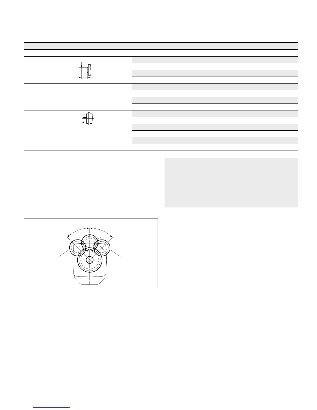
Effect of radial force Fq on the service life of bearings
By selecting a suitable direction of radial force F
q
, the load
on the bearings, caused by the internal rotary group forces
can be reduced, thus optimizing the service life of the
bearings. Recommended position of mating gear is dependent on direction of rotation. Examples:
Notes
▶ The values given are maximum values and do not apply
to continuous operation.
▶ The permissible axial force in –F
ax
direction is to be
avoided, because thereby the bearing life is reduced.
▶ Special requirements apply in the case of belt drives.
Please contact us.
▼ Toothed gear output drive
φ
o
p
t
=
4
5
°
φ
o
p
t
=
4
5
°
21
3
1 Direction of rotation "counter-clockwise", pressure at port B
2 Direction of rotation "clockwise", pressure at port A
3 Bidirectional direction of rotation
1) With intermittent operation
Bosch Rexroth Corp., RE-A 91610/12.2015
10 A6VM series 71 | Axial piston variable motor
HP – Proportional hydraulic control
HP – Proportional hydraulic control
The proportional hydraulic control provides infinite adjustment of the displacement. The control is proportional to
the pilot pressure applied to port X.
HP1, HP2 positive control
▶ Beginning of control at V
g min
(minimum torque, maxi-
mum permissible speed at minimum pilot pressure)
▶ End of control at V
g max
(maximum torque, minimum
speed at maximum pilot pressure)
HP5, HP6 negative control
▶ Beginning of control at V
g max
(maximum torque, mini-
mum speed at minimum pilot pressure)
▶ End of control at V
g min
(minimum torque, maximum
permissible speed at maximum pilot pressure)
Note
▶ Maximum permissible pilot pressure: pSt=1450psi (100bar)
▶ The control oil is internally taken from the high pressure
side of the motor (A or B). For reliable control, an operating pressure of at least 435psi (30bar) is required in
A (B). If a control operation is performed at an operating pressure <435psi (30bar), an auxiliary pressure of
at least 435psi (30bar) must be applied at port G via
an external check valve. For lower pressures, please
contact us.
Please note that pressures up to 7250psi (500bar) can
occur at port G.
▶ Please state the desired beginning of control in plain text
when ordering, e. g.: beginning of control at 145psi (10bar).
▶ The beginning of control and the HP characteristic curve
are influenced by the case pressure. An increase in case
pressure causes an increase in the beginning of control
(see page 6) and thus a parallel displacement of the
characteristic.
▶ A leakage flow of maximum 0.08gpm (0.3l/min) can
escape at port X due to internal leakage (operating pressure > pilot pressure). The control is to be suitably
configured to avoid an independent build-up of pilot
pressure.
Response time damping
The response time damping is influencing the stroke characteristics of the motor and thus the reaction speed of the
machine.
Standard with Size 60 to 215
HP without damping.
HP.D with throttle pin on both sides, symmetrical (as to
table)
Option with Size 60 to 215
HP with throttle pin on both sides, symmetrical (as to
table)
▼ Overview Throttle Pins
Size 60 85 115 150 170 215
Groove
size
[inch] 0.018 0.018 0.022 0.022 0.022 0.026
[mm] 0.45 0.45 0.55 0.55 0.55 0.65
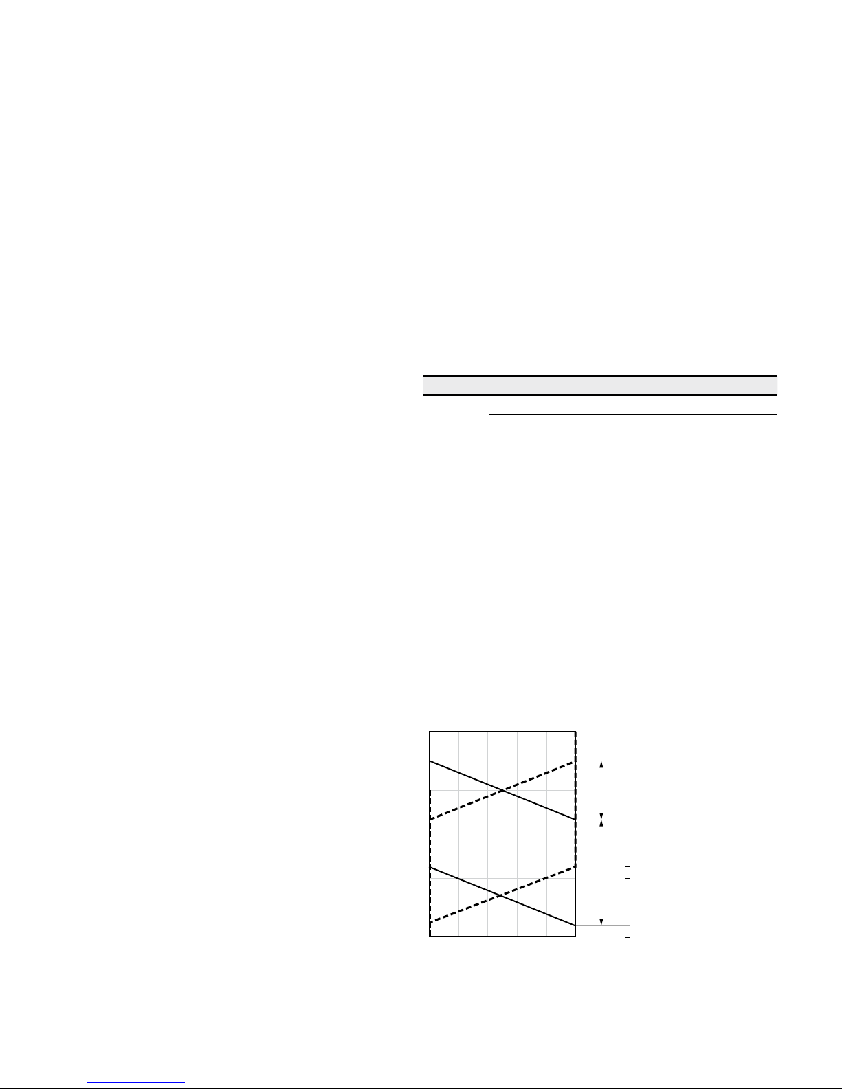
HP1, HP5 pilot pressure increase ΔpSt = 145psi (10bar)
HP1 positive control
A pilot pressure increase of 145psi (10bar) at port X
results in an increase in displacement from V
g min
to V
g max
.
HP5 negative control
A pilot pressure increase of 145psi (10bar) at port X
results in a decrease in displacement from
V
g max
to
V
g min
.
▶ Beginning of control, setting range 30 to 290psi (2 to
20bar)
▶ Standard setting:
Beginning of control at 45psi (3bar) (end of control at
190psi (13bar))
▼ Characteristic curve
0 0.2 0.4 0.6 0.8 1.0
V
g min
V
g max
Vg / V
g max
HP5 HP1
510 (35)
435 (30)
365 (25)
290 (20)
220 (15)
175 (12)
145 (10)
75 (5)
30 (2)
Beginning of control
setting range
Displacement
Pilot pressure p
St
[psi (bar)]
Pilot
pressure
increase
RE-A 91610/12.2015, Bosch Rexroth Corp.
Axial piston variable motor | A6VM series 71
HP – Proportional hydraulic control
11
HP2, HP6 pilot pressure increase ΔpSt = 365psi (25bar)
HP2 positive control
A pilot pressure increase of 365psi (25bar) at port X
results in an increase in displacement from V
g min
to V
g max
.
HP6 negative control
A pilot pressure increase of 365psi (25bar) at port X
results in a decrease in displacement from
V
g max
to
V
g min
.
▶ Beginning of control, setting range 75 to 725psi (5 to
50bar)
▶ Standard setting:
Beginning of control at 145psi (10bar) (end of control
at 510psi (35bar))
▼ Characteristic curve
1000 (70)
870 (60)
725 (50)
580 (40)
510 (35)
435 (30)
290 (20)
145 (10)
75 (5)
0 0.2 0.4 0.6 0.8 1.0
V
g min
V
g max
Vg / V
g max
HP6 HP2HP6 HP2
Beginning of
control setting
range
Displacement
Pilot pressure p
St
[psi (bar)]
Pilot
pressure
increase
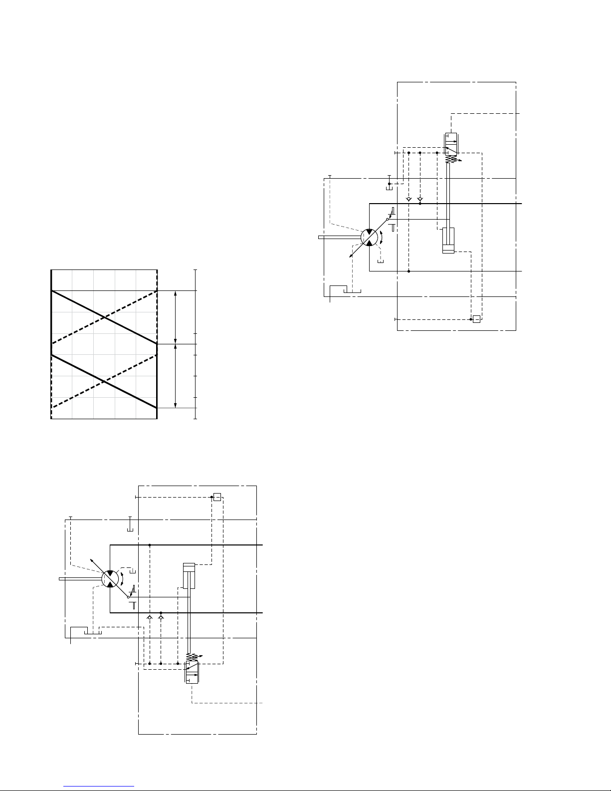
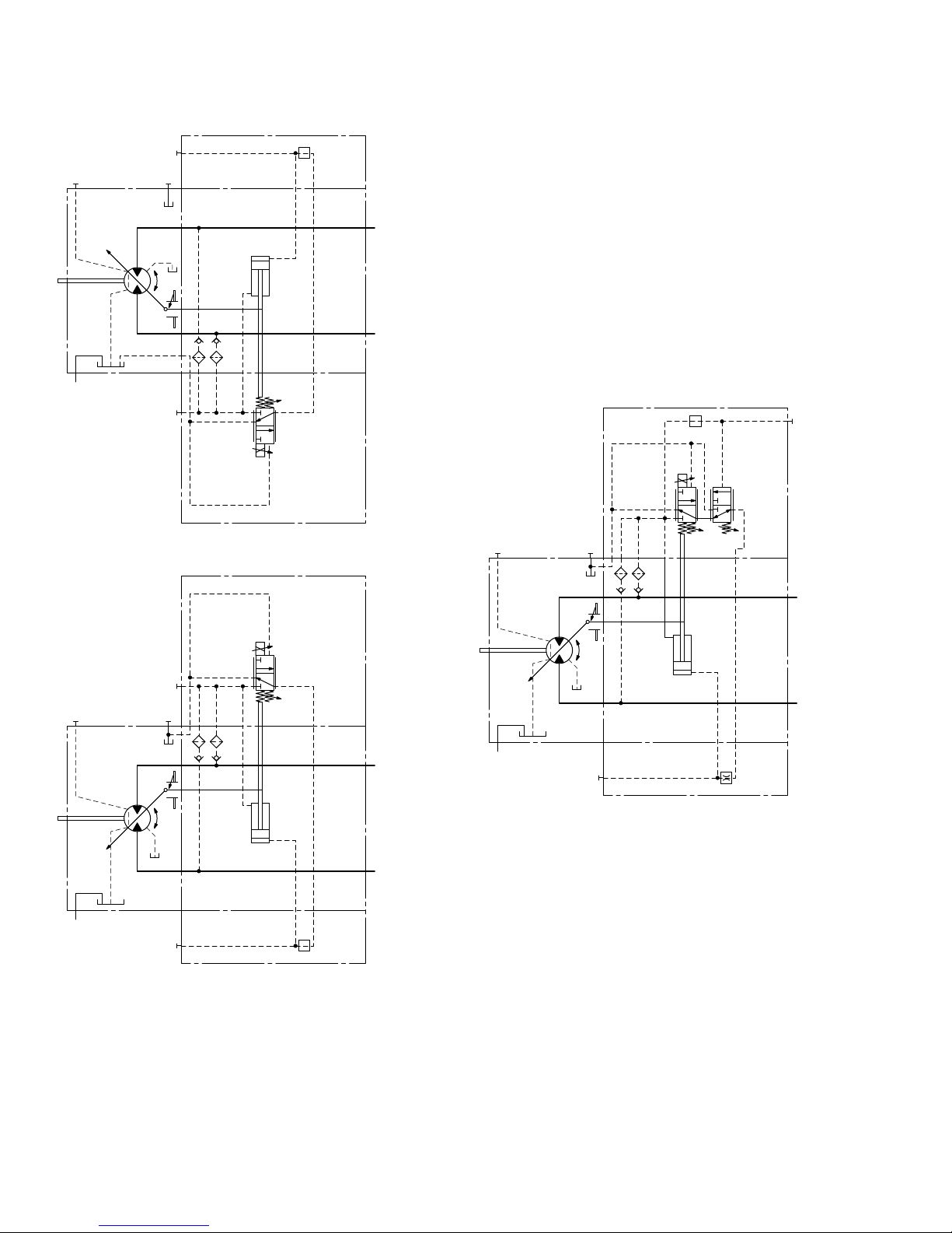
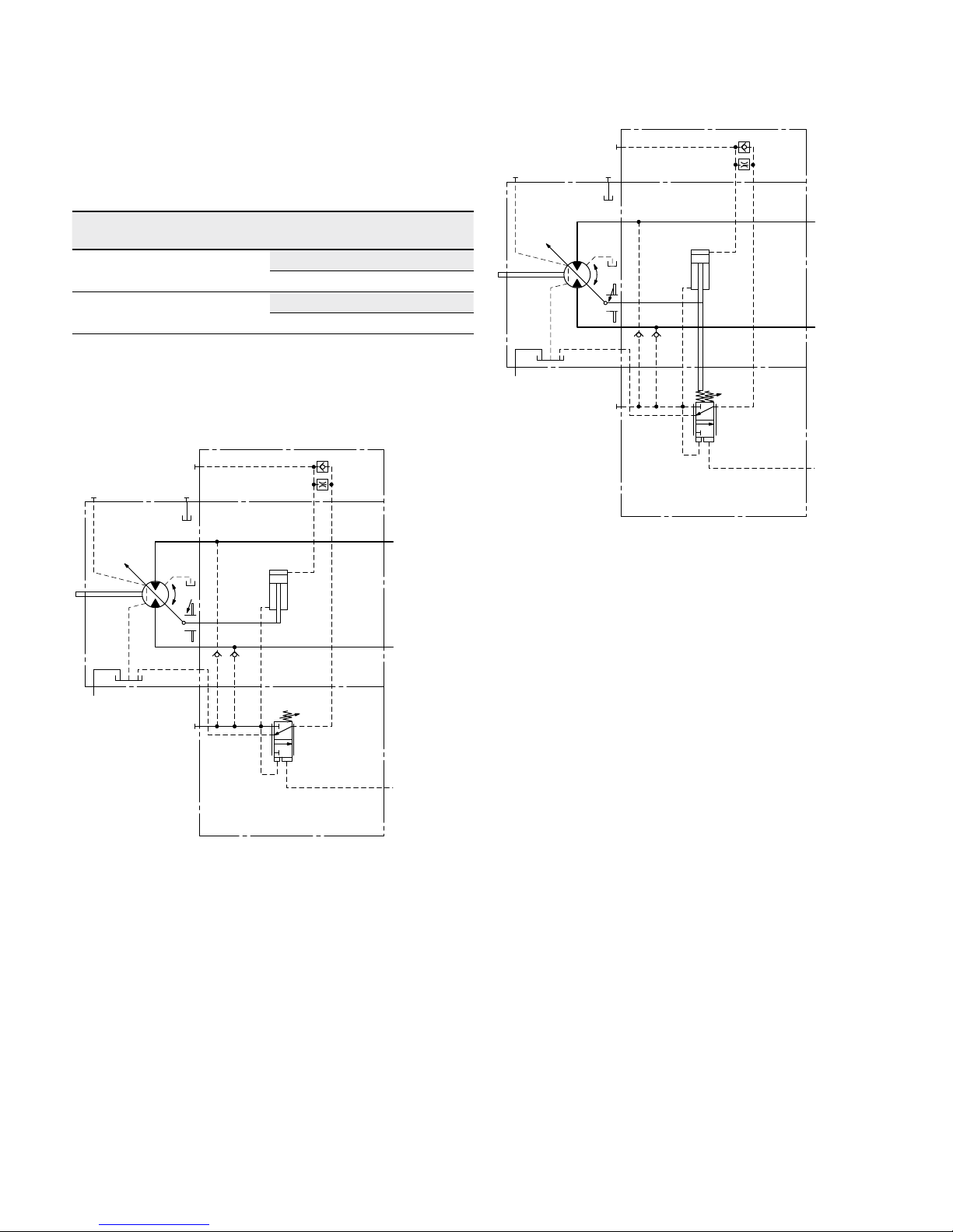
▼ Circuit diagram HP1, HP2 (positive control)
B
A
M
1
T
2
T
1
G
X
V
g min
V
g max
U
▼ Circuit diagram HP5, HP6 (negative control)
T
2
T
1
M
1
V
g min
V
g max
B
A
U
X
G
Bosch Rexroth Corp., RE-A 91610/12.2015
12 A6VM series 71 | Axial piston variable motor
HP – Proportional hydraulic control
HP5D1, HP6D1 Pressure control, fixed setting
The pressure control overrides the HP control function.
Ifthe load torque or a reduction in motor swivel angle
causes the system pressure to reach the setpoint value of
the pressure control, the motor will swivel towards a larger
displacement.
The increase in the displacement and the resulting reduction in pressure cause the control deviation to decrease.
With the increase in displacement the motor develops more
torque, while the pressure remains constant.
Setting range of the pressure control valve 1150 to6500psi
(80 to 450bar)
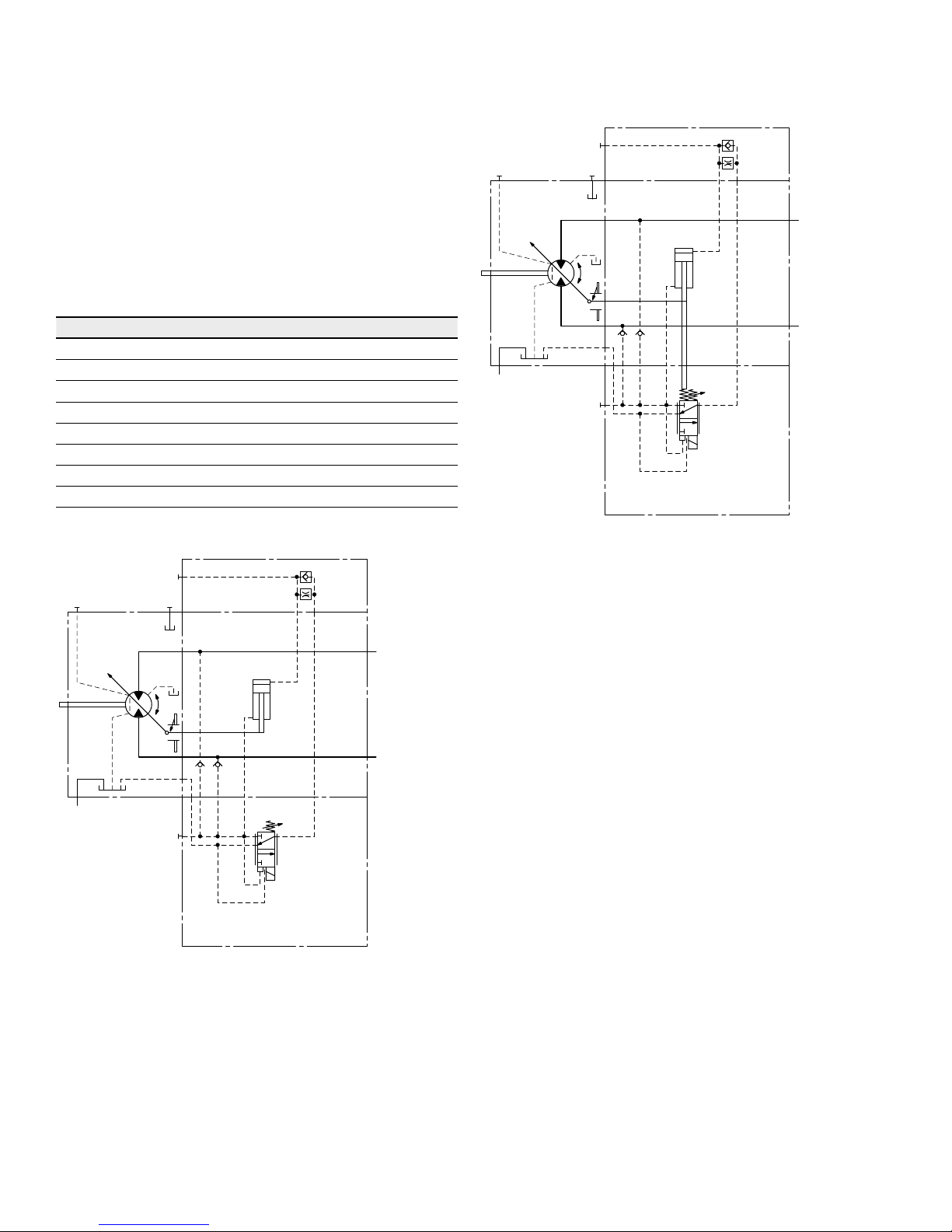
▼ Circuit diagram HP5D1, HP6D1 (negative control)
T
2
T
1
M
1
V
g min
V
g max
B
A
G
X
U
RE-A 91610/12.2015, Bosch Rexroth Corp.
13 Axial piston variable motor | A6VM series 71
EP – Proportional electric control
EP – Proportional electric control
The proportional electric control provides infinite setting of
the displacement. Control is proportional to the electric
control current applied to the solenoid.
EP1, EP2 positive control
▶ Beginning of control at V
g min
(minimum torque, maxi-
mum permissible speed at minimum control current)
▶ End of control at V
g max
(maximum torque, minimum
speed at maximum control current)
EP5, EP6 negative control
▶ Beginning of control at V
g max
(maximum torque, mini-
mum speed at minimum control current)
▶ End of control at V
g min
(minimum torque, maximum
permissible speed at maximum control current)
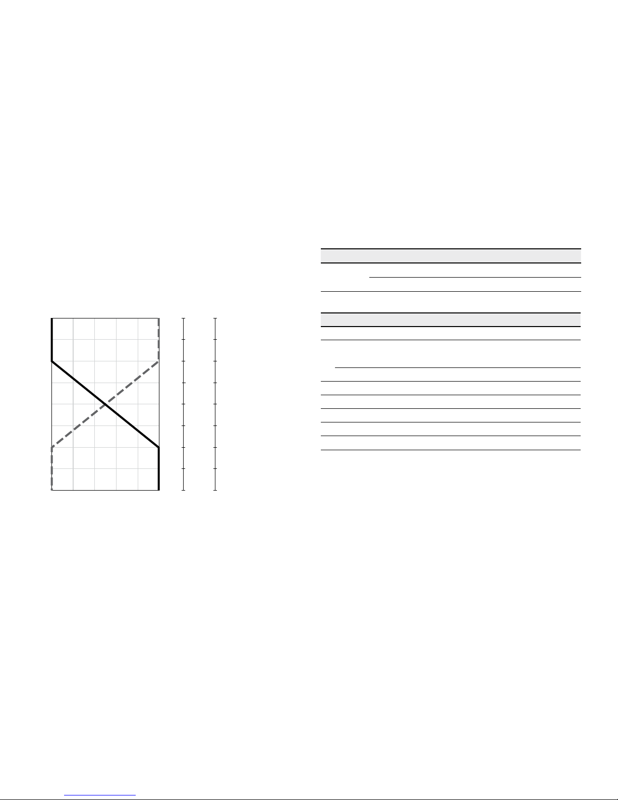
▼ Characteristic curve
EP5, EP6 EP1, EP2
0 0.2 0.4 0.6 0.8 1.0
V
g min
Vg / V
g max
V
g max
1600
max
1400
1200
1000
800
600
400
200
800
max
700
600
500
400
300
200
100
EP5
EP1
(12 V)
EP6
EP2
(24 V)
Note
The control oil is internally taken out of the high pressure
side of the motor (A or B). For reliable control, an operating
pressure of at least 435psi (30bar) is necessary in A (B).
If a control operation is performed at an operating pressure
<435psi (30bar), an auxiliary pressure of at least 435psi
(30bar) must be applied at port G using an external check
valve. For lower pressures, please contact us.
Please note that pressures up to 7250psi (500bar) can
occur at port G.
Response time damping
The response time damping is influencing the stroke characteristics of the motor and thus the reaction speed of the
machine.
Standard with Size 60 to 215
EP without damping.
EP.D with throttle pin on both sides, symmetrical (as to table)
Option with Size 60 to 115
EP with throttle pin on both sides, symmetrical (as to table)
▼ Overview Throttle Pins
Size 60 85 115 150 170 215
Groove
size
[inch] 0.018 0.018 0.022 0.022 0.022 0.026
[mm] 0.45 0.45 0.55 0.55 0.55 0.65
Technical data, solenoid EP1, EP5 EP2, EP6
Voltage 12V (±20%) 24V (±20%)
Control current
Beginning of control 400mA 200mA
End of control 1200mA 600mA
Current limit 1.54A 0.77A
Nominal resistance (at 68°F (20°C)) 5.5Ω 22.7Ω
Dither frequency 100Hz 100Hz
Duty cycle 100% 100%
Type of protection: see connector version on page 62
Various BODAS controllers with application software and
amplifiers are available for controlling the proportional
solenoids.
Further information can also be found on the internet at
www.boschrexroth.com/mobile-electronics.
Bosch Rexroth Corp., RE-A 91610/12.2015
14 A6VM series 71 | Axial piston variable motor
EP – Proportional electric control
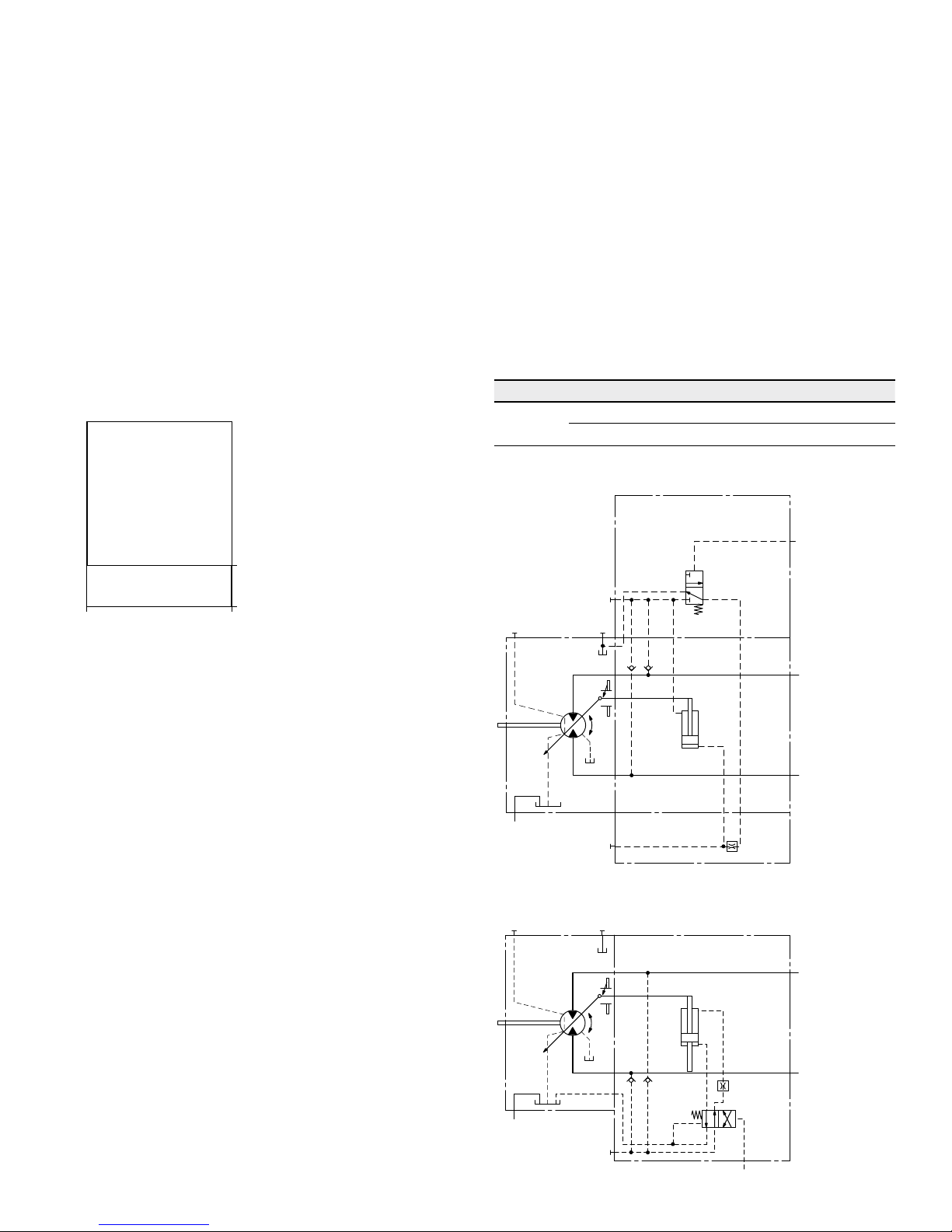
▼ Circuit diagram EP1, EP2 (positive control)
B
A
M
1
T
2
T
1
G
V
g min
V
g max
U
▼ Circuit diagram EP5, EP6 (negative control)
U
T
2
T
1
M
1
V
g min
V
g max
B
A
G
EP5D1, EP6D1 Pressure control, fixed setting
The pressure control overrides the EP control function. If
the load torque or a reduction in motor swivel angle causes
the system pressure to reach the setpoint value of the
pressure control, the motor will swivel towards a larger
displacement.
The increase in the displacement and the resulting reduction in pressure cause the control deviation to decrease.
With the increase in displacement the motor develops more
torque, while the pressure remains constant.
Setting range of the pressure control valve 1150 to 6500psi
(80 to 450bar)
▼ Circuit diagram EP5D1, EP6D1 (negative control)
U
T2
T
1
V
g min
V
g max
B
A
G
M
1
RE-A 91610/12.2015, Bosch Rexroth Corp.
Axial piston variable motor | A6VM series 71
HZ – Two-point hydraulic control
15
HZ – Two-point hydraulic control
The two-point hydraulic control allows the displacement to
be set to either V
g min
or V
g max
by switching the pilot pres-
sure at port X on or off.
HZ5, HZ7 negative control
▶ Position at V
g max
(without pilot pressure, maximum
torque, minimum speed)
▶ Position at V
g min
(with pilot pressure >145psi (10bar)
activated, minimum torque, maximum permissible
speed)
▼ Characteristic curve HZ5, HZ7
V
g min
V
g max
Displacement
0
145 (10)
Pilot pressure Δp
S
[psi (bar)]
1450 (100)
Note
▶ Maximum permissible pilot pressure: 1450psi (100bar)
▶ The control oil is internally taken out of the high pres-
sure side of the motor (A or B). For reliable control, an
operating pressure of at least 435psi (30bar) is
required in A (B). If a control operation is performed at
an operating pressure < 435psi (30bar), an auxiliary
pressure of at least 435psi (30bar) must be applied at
port G via an external check valve. For lower pressures,
please contact us.
Please note that pressures up to 7250psi (500bar) can
occur at port G.
Response time damping
The response time damping is influencing the stroke characteristics of the motor and thus the reaction speed of the
machine.
Standard with Size 150 to 215
HZ5 with throttle pin on both sides, symmetrical (as to table)
Standard with Size 60 to 115
HZ7 (Synchronizing piston) with throttle pin on both sides,
symmetrical (as to table)
▼ Overview Throttle Pins
Size 60 85 115 150 170 215
Groove
size
[inch] 0.012 0.012 0.012 0.022 0.022 0.026
[mm] 0.30 0.30 0.30 0.55 0.55 0.65
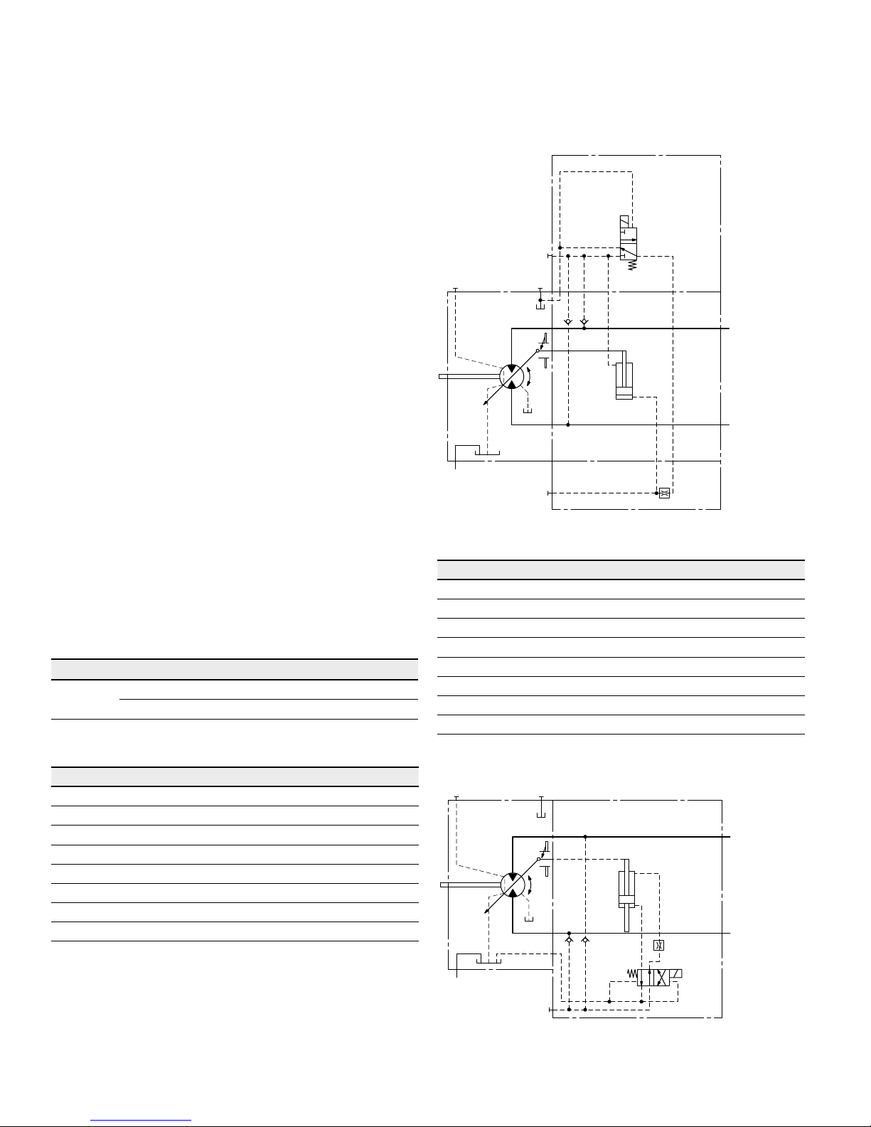
▼ Circuit diagram HZ5 (negative control) size 150 to 215
T
2
T
1
M
1
V
g min
V
g max
B
A
X
G
U
▼ Circuit diagram HZ7 (negative control) size 60 to 115
T
1
U
T
2
X
G
V
g min
V
g max
B
A
Bosch Rexroth Corp., RE-A 91610/12.2015
16 A6VM series 71 | Axial piston variable motor
EZ – Two-point electric control
EZ – Two-point electric control
The two-point electric control allows the displacement to
be set to either V
g min
or V
g max
by switching the electric
current to a switching solenoid on or off.
Note
The control oil is internally taken out of the high pressure
side of the motor (A or B). For reliable control, an operating pressure of at least 435psi (30bar) is required in A
(B). If a control operation is performed at an operating
pressure <435psi (30bar), an auxiliary pressure of at least
435psi (30bar) must be applied at port G via an external
check valve. For lower pressures, please contact us.
Please note that pressures up to 7250psi (500bar) can
occur at port G.
Response time damping
The response time damping is influencing the stroke characteristics of the motor and thus the reaction speed of the
machine.
Standard with Size 150 to 215
EZ5, EZ6 with throttle pin on both sides, symmetrical (as to
table)
Option with Size 60 to 115
EZ7, EZ8 (Synchronizing piston) with throttle pin on both
sides, symmetrical (as to table)
▼ Overview Throttle Pins
Size 60 85 115 150 170 215
Groove
size
[inch] 0.012 0.012 0.012 0.022 0.022 0.026
[mm] 0.30 0.30 0.30 0.55 0.55 0.65
Sizes 150 to 215
Technical data, solenoid with DIA37 EZ5 EZ6
Voltage 12V (±20%) 24V (±20%)
Position V
g max
de-energized de-energized
Position V
g min
energized energized
Nominal resistance (at 68°F (20°C)) 5.5Ω 21.7Ω
Nominal power 26.2W 26.5W
Minimum required active current 1.32A 0.67A
Duty cycle 100% 100%
Type of protection: see connector version on page 62
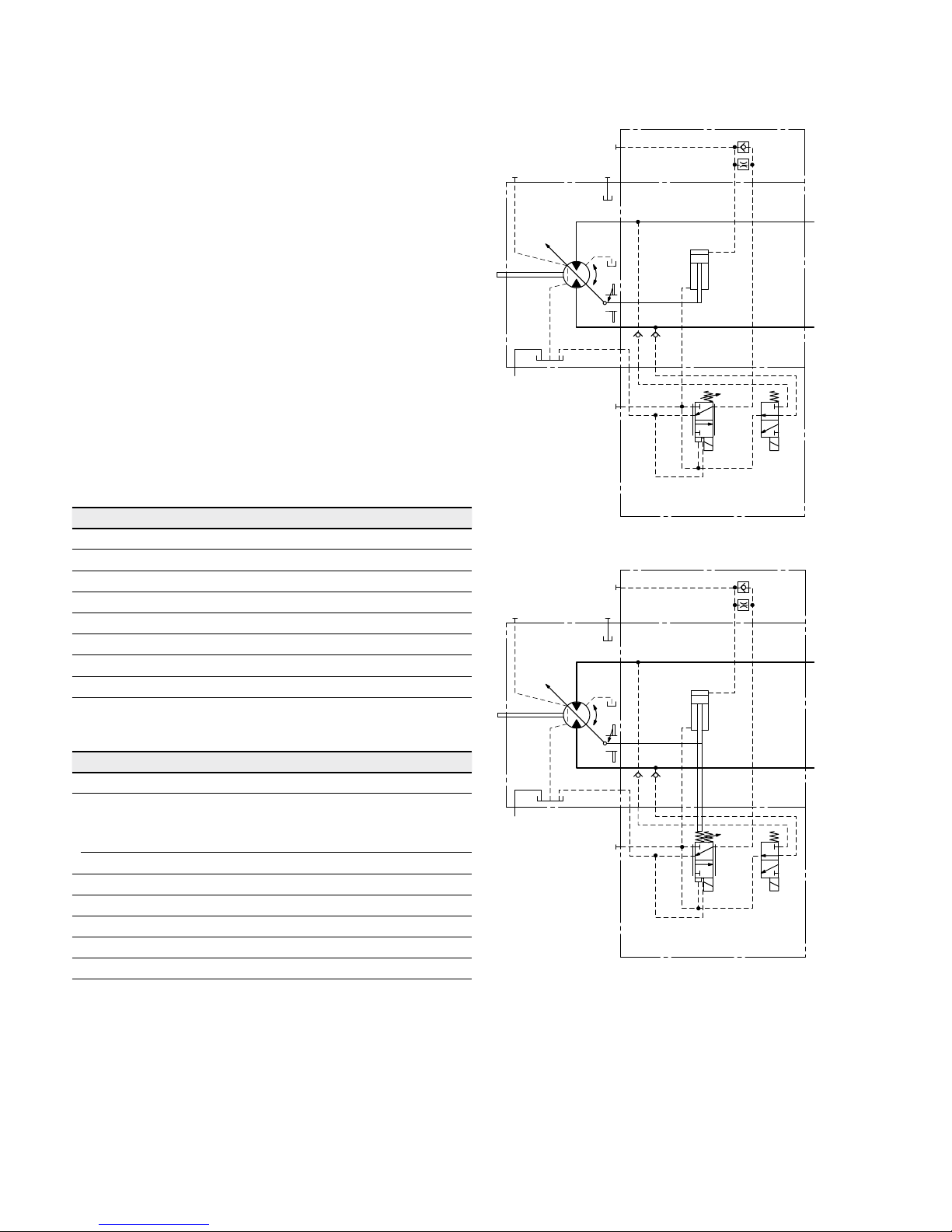
▼ Circuit diagram EZ5, EZ6 (negative control) size 150 to 215
U
T
2
T
1
M
1
V
g min
V
g max
B
A
G
Sizes 60 to 115
Technical data, solenoid with DIA45 EZ7 EZ8
Voltage 12V (±20%) 24V (±20%)
Position V
g max
de-energized de-energized
Position V
g min
energized energized
Nominal resistance (at 68°F (20°C)) 4.8Ω 19.2Ω
Nominal power 30W 30W
Minimum required active current 1.5A 0.75A
Duty cycle 100% 100%
Type of protection: see connector version on page 62
▼ Circuit diagram EZ7, EZ8 (negative control) size 60 to 115
T
1
U
T
2
G
B
A
V
g min
V
g max

RE-A 91610/12.2015, Bosch Rexroth Corp.
Axial piston variable motor | A6VM series 71
HA – Automatic high-pressure related control
17
HA – Automatic high-pressure related control
The automatic high-pressure related control adjusts the
displacement automatically depending on the operating
pressure.
The displacement of the A6VM motor with HA control is
V
gmin
(maximum speed and minimum torque). The control
unit internally measures the operating pressure at A or B
(no control line required) and upon reaching the set beginning of control, the controller swivels the motor from V
g min
to V
g max
with increase of operating pressure. The displace-
ment is modulated between V
gmin
and V
gmax
, thereby
depending on load conditions.
HA1, HA2 positive control
▶ Beginning of control at V
g min
(minimum torque, maxi-
mum speed)
▶ End of control at V
g max
(maximum torque, minimum
speed)
Note
▶ For safety reasons, winch drives are not permissible
with beginning of control at V
g min
(standard for HA).
▶ The control oil is internally taken out of the high pres-
sure side of the motor (A or B). For reliable control, an
operating pressure of at least 435psi (30bar) is
required in A (B). If a control operation is performed at
an operating pressure < 435psi (30bar), an auxiliary
pressure of at least 435psi (30bar) must be applied at
port G via an external check valve. For lower pressures,
please contact us.
Please note that pressures up to 7250psi (500bar) can
occur at port G.
▶ The beginning of control and the HA.T3 characteristic
curve are influenced by case pressure. An increase in
case pressure causes an increase in the beginning of
control (see page 6) and thus a parallel shift of the
characteristic.
Response time damping
The response time damping is influencing the stroke characteristics of the motor and thus the reaction speed of the
machine.
Standard with Size 60 to 215
HA1,2 with one-sided throttle pin, the throttling occurs
from V
g min
to V
g max
. (as to table)
▼ Overview Throttle Pins
Size 60 85 115 150 170 215
Groove
size
[inch] 0.018 0.018 0.022 0.022 0.022 0.022
[mm] 0.45 0.45 0.55 0.55 0.55 0.65
Standard with Size 60 to 215
HA1, 2 with one sided throttle pin effects the stroking time
of
the motor from Vg min to Vg max. (as to table)
▼ Overview Throttle Screw
Size 60 85 115 150 170 215
Groove
size
[inch] 0.031 0.031 0.031 0.031 0.031 0.031
[mm] 0.80 0.80 0.80 0.80 0.80 0.80
Bosch Rexroth Corp., RE-A 91610/12.2015
18 A6VM series 71 | Axial piston variable motor
HA – Automatic high-pressure related control
HA1 with minimum pressure increase, positive control
An operating pressure increase of Δp ≤approx.145psi
(10bar) results in an increase in displacement from V
g min
towards V
g max
.
Beginning of control, setting range
1150 to 5100psi (80 to
350bar)
Please state the desired beginning of control in plain text
when ordering, e. g.: beginning of control at 4350psi
(300bar).
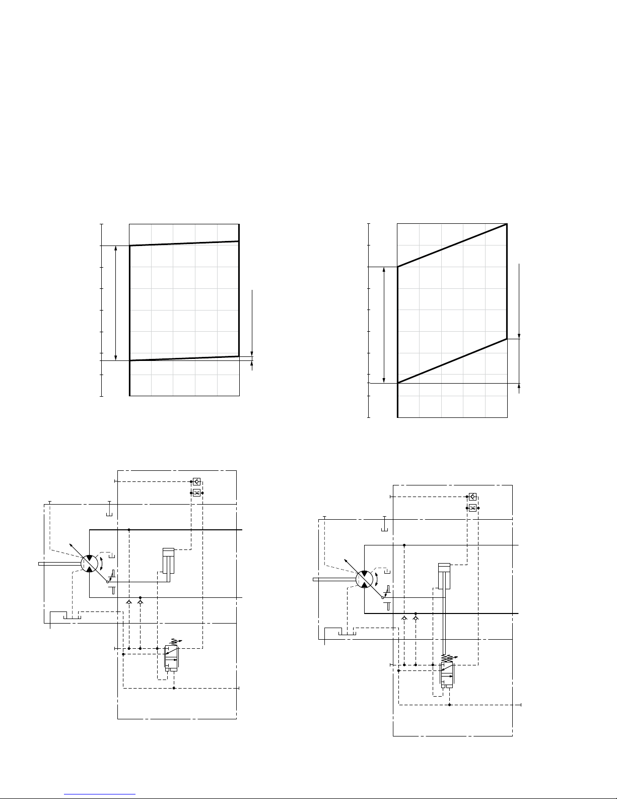
▼ Characteristic curve HA1
5800 (400)
5100 (350)
4350 (300)
3600 (250)
2900 (200)
2200 (150)
1450 (100)
1150 (80)
725 (50)
0
V
g min
V
g max
Vg / V
g max
0 0.2 0.4 0.6 0.8 1.0
Pressure increase
Δp≤approx.
145psi (10bar)
Operating pressure p [psi (bar)]
Beginning of control
setting range
Displacement
▼ Circuit diagram HA1
B
A
M
1
T
2
T
1
V
g min
V
g max
G
U
X
HA2 with pressure increase, positive control
An operating pressure increase of Δp ≤approx.1450psi
(100bar) results in an increase in displacement from V
g min
to V
g max
.
Beginning of control, setting range
1150 to 5100psi (80 to
350bar)
Please state the desired beginning of control in plain text
when ordering, e. g.: beginning of control at 2900psi
(200bar)
▼ Characteristic curve HA2
6500 (450)
5800 (400)
5100 (350)
4350 (300)
3600 (250)
2900 (200)
2200 (150)
1450 (100)
1150 (80)
725 (50)
0
V
g min
V
g max
Vg / V
g max
0 0.2 0.4 0.6 0.8 1.0
Pressure increase
Δp≤approx.
1450psi (100bar)
Operating pressure p [psi (bar)]
Beginning of control
setting range
Displacement
▼ Circuit diagram HA2
B
A
M
1
T
2
T
1
G
X
V
g min
V
g max
U
RE-A 91610/12.2015, Bosch Rexroth Corp.
Axial piston variable motor | A6VM series 71
HA – Automatic high-pressure related control
19
HA.T3 hydraulic override, remote control, proportional
With the HA.T3 control, the beginning of control can be
influenced by applying a pilot pressure to port X.
For each 15psi(1bar) of pilot pressure increase, the
beginning of control is reduced by 250psi(17bar).
Beginning of control setting 4350psi
(300bar)
4350psi
(300bar)
Pilot pressure at port X 0 psi 145psi
0 bar (10bar)
Beginning of control at 4350psi 1900psi
(300bar) (130bar)
Note
Maximum permissible pilot pressure 1450psi (100bar).
▼ Circuit diagram HA1.T3
B
A
M
1
T
2
T
1
V
g min
V
g max
X
U
G
▼ Circuit diagram HA2.T3
B
A
M
1
T
2
T
1
G
X
V
g min
V
g max
U
Bosch Rexroth Corp., RE-A 91610/12.2015
20 A6VM series 71 | Axial piston variable motor
HA – Automatic high-pressure related control
HA.U1, HA.U2 electric override, two-point
With the HA.U1 or HA.U2 control, the beginning of control
can be overridden by an electric signal to a switching solenoid. When the override solenoid is energized, the variable
motor swivels to maximum swivel angle, without intermediate position.
The beginning of control can be set between 1150 and
4350psi (80 and 300bar) (specify required setting in plain
text when ordering).
Technical data, solenoid with DIA45 U1 U2
Voltage 12 V (±20 %) 24 V (±20 %)
No override de-energized de-energized
Position V
g max
energized energized
Nominal resistance (at 68°F (20°C)) 4.8Ω 19.2Ω
Nominal power 30 W 30 W
Minimum required active current 1.5A 0.75A
Duty cycle 100 % 100 %
Type of protection: see connector version on page 62
▼ Circuit diagram HA1U1, HA1U2
G
B
A
M
1
T
2
T
1
V
g min
V
g max
U
▼ Circuit diagram HA2U1, HA2U2
M
1
T
2
T
1
B
A
V
g min
V
g max
G
U
RE-A 91610/12.2015, Bosch Rexroth Corp.
Axial piston variable motor | A6VM series 71
HA – Automatic high-pressure related control
21
HA.R1, HA.R2 electric override, electric travel direction
valve
With the HA.R1 or HA.R2 control, the beginning of control
can be overridden by an electric signal to switching solenoid b. When the override solenoid is energized, the variable motor swivels to maximum swivel angle, without intermediate position.
The travel direction valve ensures that the preselected
pressure side of the hydraulic motor (A or B) is always
connected to the HA control, and thus determines the
swivel angle, even if the high-pressure side changes
(e. g. -travel drive during a downhill operation). This
thereby prevents undesired jerky deceleration and/or braking characteristics.
The travel direction valve (see page 24) is either pressure
spring or switched by energizing switching solenoid a,
depending on the direction of rotation (travel direction).
Electric override
Technical data, solenoid b with DIA45 R1 R2
Voltage
12 V (±20 %) 24 V (±20 %)
No override de-energized de-energized
Position V
g max
energized energized
Nominal resistance (at 68°F (20°C)) 4.8Ω 19.2Ω
Nominal power 30 W 30 W
Minimum required active current 1.5A 0.75A
Duty cycle 100 % 100 %
Type of protection: see connector version on page 62
Travel direction valve, electric
Technical data, solenoid a with DIA37 R1 R2
Voltage
12 V (±20 %) 24 V (±20 %)
Direction
of rotation
Operating
pressure in
ccw B energized energized
cw A de-energized de-energized
Nominal resistance (at 68°F (20°C)) 5.5Ω 21.7Ω
Nominal power 26.2 W 26.5 W
Minimum required active current 1.32 A 0.67 A
Duty cycle 100 % 100 %
Type of protection: see connector version on page 62
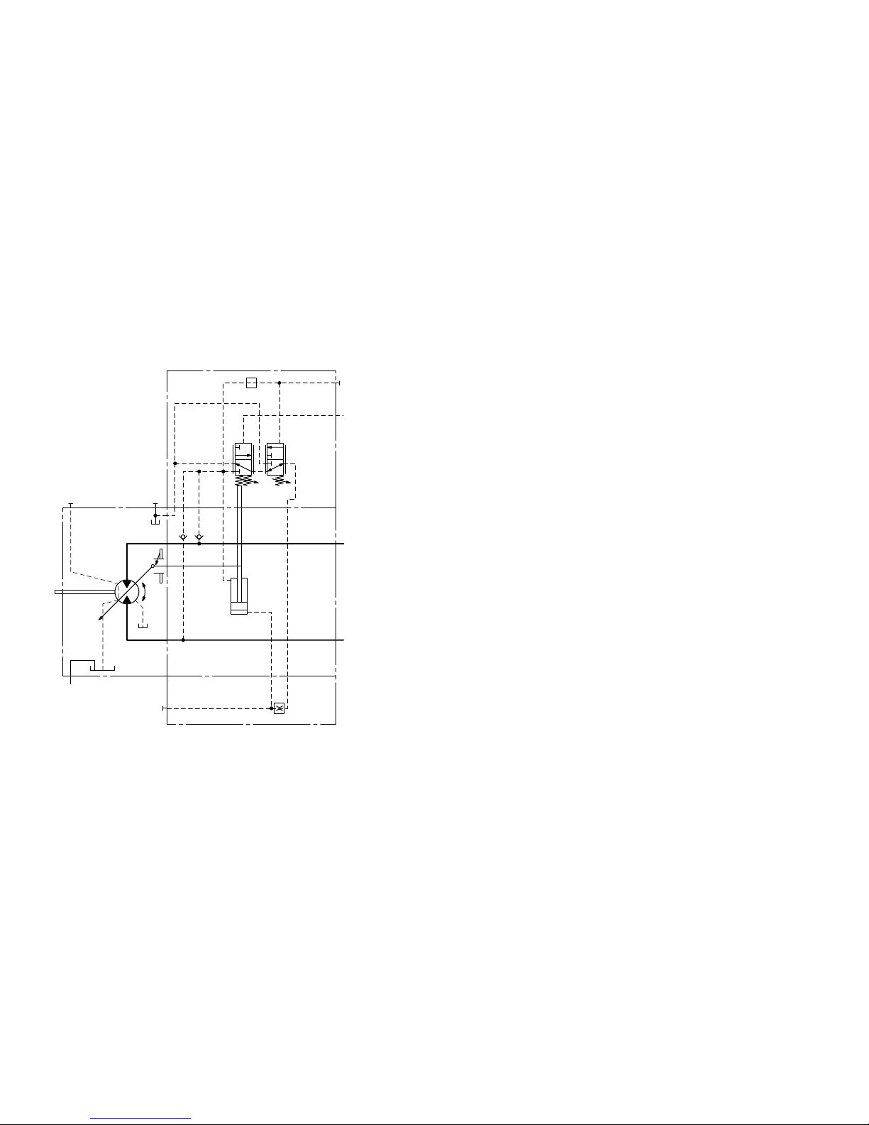
▼ Circuit diagram HA1R1, HA1R2
ab
B
A
M
1
T
2
T
1
V
g min
V
g max
U
G
▼ Circuit diagram HA2R1, HA2R2
M
1
T
2
T
1
G
B
A
V
g min
V
g max
U
a
b
Bosch Rexroth Corp., RE-A 91610/12.2015
22 A6VM series 71 | Axial piston variable motor
DA – Automatic speed-related control
DA – Automatic speed-related control
The variable motor A6VM with automatic speed-related
control, type DA, is intended for use in hydrostatic travel
drives in combination with the variable pump A4VG with
DAcontrol.
A drive-speed-related pilot pressure signal is generated by
the A4VG variable pump, and that signal, together with the
operating pressure, regulates the swivel angle of the
hydraulic motor.
Increasing pump speed, i.e. increasing pilot pressure,
causes the motor to swivel to a smaller displacement
(lower torque, higher speed), depending on the operating
pressure.
If the operating pressure exceeds the pressure setpoint set
on the controller, the variable motor swivels to a larger
displacement (higher torque, lower speed).
▶ Pressure ratio p
St/pHD
= 5/100
DA closed loop control is only suitable for certain types of
drive systems and requires review of the engine and vehicle
parameters to ensure that the motor is used correctly and
that machine operation is safe and efficient. We recommend
that all DA applications be reviewed by a Bosch Rexroth
application engineer.
Detailed information is available from our sales organization.
Note
The beginning of control and the DA characteristic curve
are influenced by case pressure. An increase in case pressure causes a decrease in the beginning of control (see
page 6) and thus a parallel shift of the characteristic.
Response time damping
The response time damping is influencing the stroke characteristics of the motor and thus the reaction speed of the
machine.
Standard with Size 60 to 215
DA with one sided throttle pin effects the stroking time of
the motor from V
g min
to V
g max
. (as to table)
▼ Overview Throttle Pins
Size 60 85 115 150 170 215
Groove
size
[inch] 0.018 0.018 0.022 0.022 0.022 0.022
[mm] 0.45 0.45 0.55 0.55 0.55 0.65
DA0 hydraulic travel direction valve, negative control
Depending on the direction of rotation (travel direction),
the travel direction valve is switched by using pilot pressures connections X
1
or X2.
Direction
of rotation
Operating
pressure in
Pilot pressure in
cw A X
1
ccw B X
2
▼ Circuit diagram DA0
M
1
T
2
T
1
V
g min
V
g max
B
A
G
X
3
X
2
X
1
U
RE-A 91610/12.2015, Bosch Rexroth Corp.
Axial piston variable motor | A6VM series 71
DA – Automatic speed-related control
23
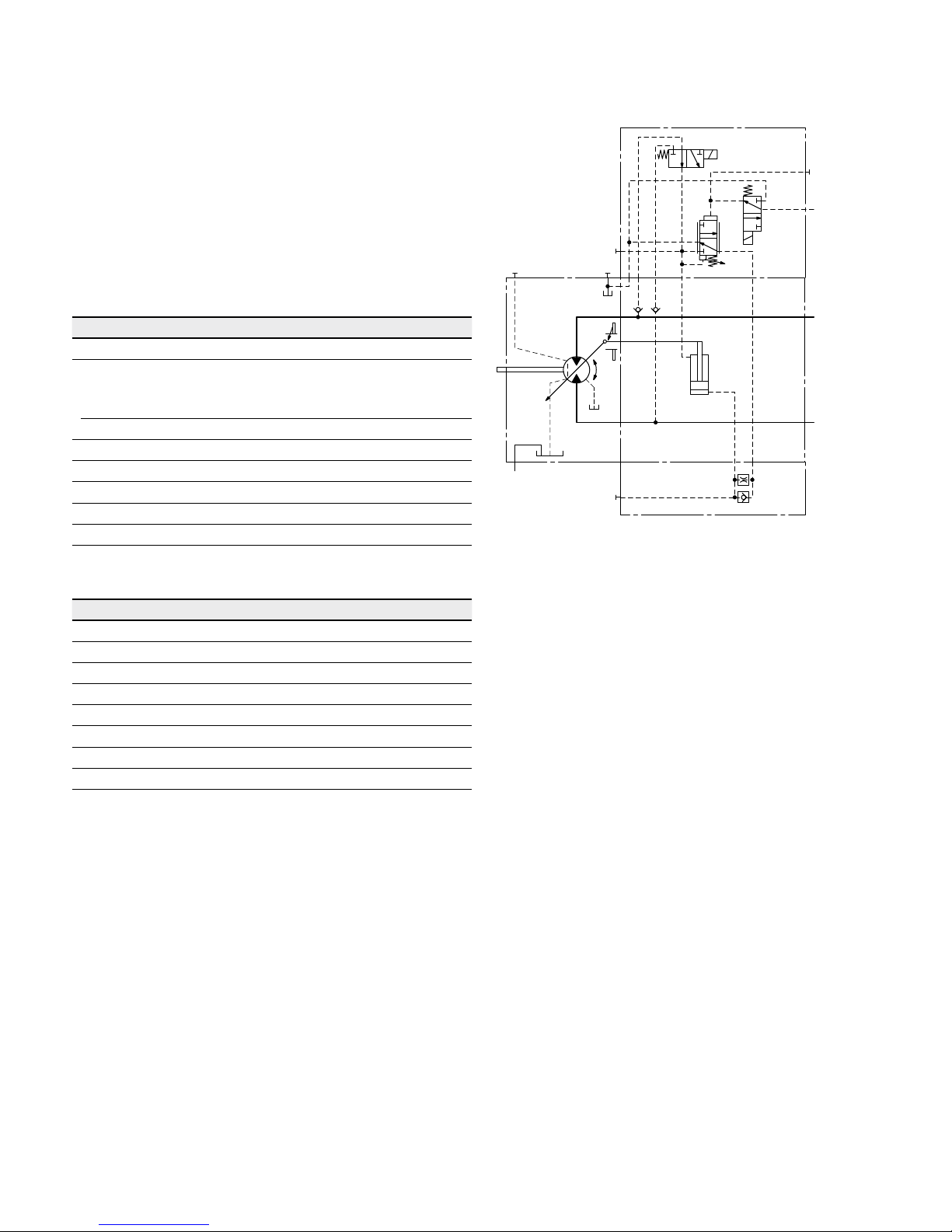
DA1, DA2 electric travel direction valve + electric
V
gmax
circuit, negative control
The travel direction valve is pressure spring offset or
switched by energizing switching solenoid a, depending on
the direction of rotation (travel direction).
When the switching solenoid b is energized, the DA control
is overridden and the motor swivels to maximum displacement (high torque, lower speed) (electric V
g max
-circuit).
Travel direction valve, electric
Technical data, solenoid a with DIA37 DA1 DA2
Voltage
12 V (±20 %) 24 V (±20 %)
Direction
of rotation
Operating
pressure in
ccw B de-energized de-energized
cw A energized energized
Nominal resistance (at 68°F (20°C)) 5.5Ω 21.7Ω
Nominal power 26.2 W 26.5 W
Minimum required active current 1.32 A 0.67 A
Duty cycle 100 % 100 %
Type of protection: see connector version on page 62
Electric override
Technical data, solenoid b with DIA37 DA1 DA2
Voltage 12 V (±20 %) 24 V (±20 %)
No override de-energized de-energized
Position V
g max
energized energized
Nominal resistance (at 68°F (20°C)) 5.5Ω 21.7Ω
Nominal power 26.2 W 26.5 W
Minimum required active current 1.32 A 0.67 A
Duty cycle 100 % 100 %
Type of protection: see connector version on page 62
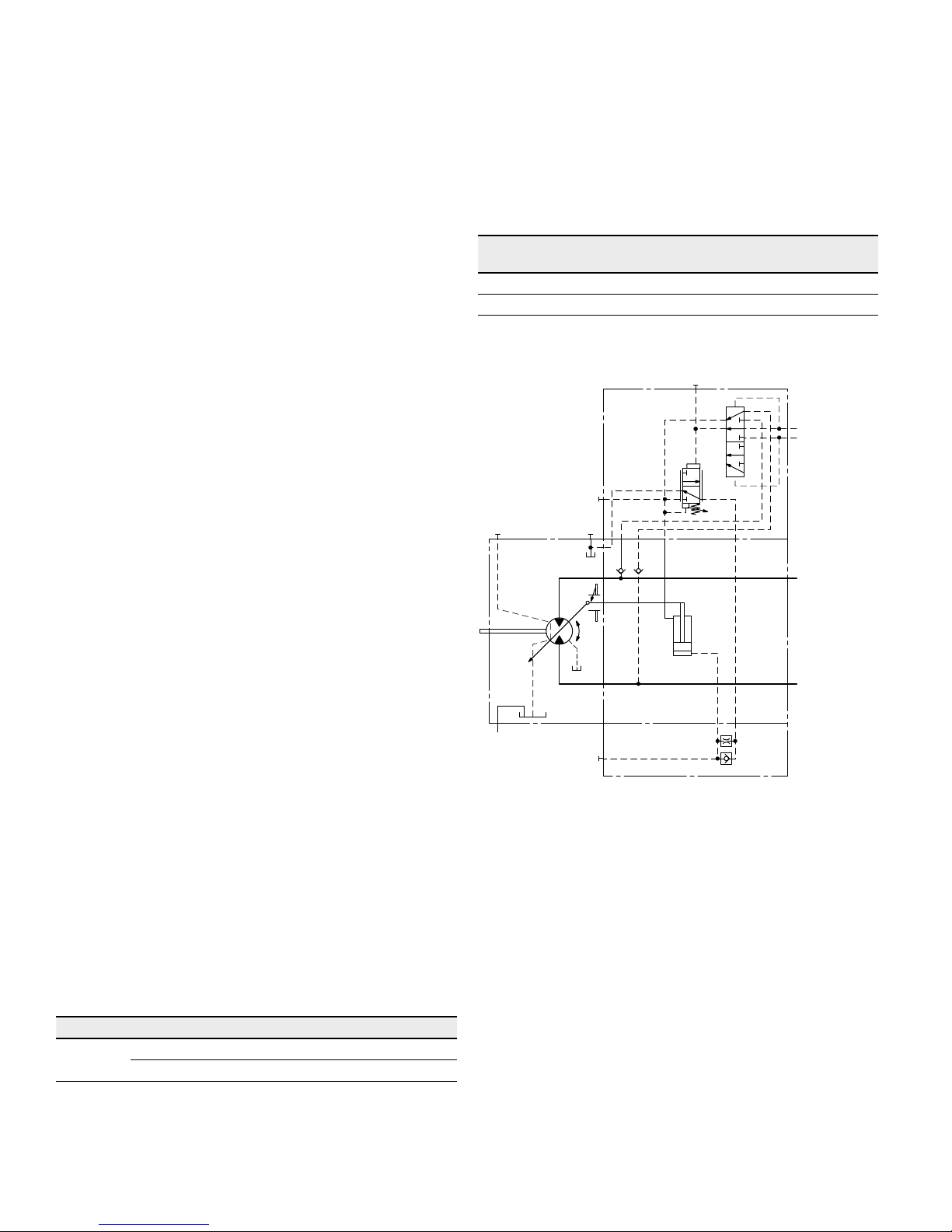
▼ Circuit diagram DA1, DA2
T
2
T
1
M
1
V
g min
V
g max
B
A
G
X
3
a
b
X
1
U
 Loading...