

Bosch Rexroth A2FM Instruction Manual
RE 91001-01-X-B2/01.2016, Bosch Rexroth AG
Details on explosion protection
▶ Field of application according to ATEX 94/9/EC
▶ Gas: II 2G ck IIB Tx in accordance with
DINEN13463‑1:2009, DINEN13463‑5:2011
Features
▶ Fixed motor with axial tapered piston rotary group of
bent‑axis design, for hydrostatic drives in open and
closed circuits.
▶ For use in mobile and stationary applications
▶ The output speed depends on the flow of the pump and
the displacement of the motor
▶ The output torque increases with the pressure differen‑
tial between the high‑pressure side and the low‑pres‑
sure side.
▶ Finely graduated sizes permit far‑reaching adaptation to
the drive concerned
▶ High power density
▶ Small dimensions
▶ High total efficiency
▶ Good starting efficiency
▶ Economical design
▶ One‑piece tapered piston with piston rings for sealing
▶ Series 61
▶ Sizes 10 to 180
▶ Nominal pressure 400bar
▶ Maximum pressure 450 bar
▶ Open and closed circuits
Axial piston fixed motor A2FM
for explosive areas
II 2G ck IIB Tx
Part II of instruction manual
according to ATEX directive
94/9/EC data sheet
RE 91001-01-X-B2
Edition: 01.2016
Replaces: 04.2009
Ordering code 2
Hydraulic fluids 3
Shaft seal 5
Flow direction 5
Speed range 5
Working pressure range 6
Technical data 7
Dimensions, sizes 10, 12, 16 10
Dimensions, sizes 23, 28, 32 12
Dimensions size 45 14
Dimensions sizes 56, 63 16
Dimensions sizes 80, 90 18
Dimensions sizes 107, 125 20
Dimensions sizes 160, 180 22
Counterbalance valve BVD 24
Installation instructions 27
Project planning notes 29
Safety instructions 29
Contents

Bosch Rexroth AG, RE 91001-01-X-B2/01.2016
2 A2FM for explosive areas | Axial piston fixed motor
Ordering code
1) Fastening thread or threaded ports, metric
2)
Threaded connections at the sides sealed with threaded plugs
3) Indicate ordering code for counterholding valve BVD separately as
per data sheet 95522.
Note the restrictions described on page 24.
Ordering code
01 02 03 04 05 06 07 08 09 10 11
A2F M / 61 W – B J
Axial piston unit
01 Bent‑axis design, fixed, , nominal pressure 400 bar, maximum pressure 450 bar
A2F
Operating mode
02 Motor (plug‑in motor A2FE, see data sheet 91008‑01‑X‑B2) M
Size (NG)
03 Geometric displacement, see Technical data on page 7
10 12 16 23 28 32 45 56 63 80 90 107 125 160 180
Series
04 Series 6, index 1
61
Direction of rotation
05 Viewed from drive shaft, bidirectional
W
Sealing material ATEX version
06 ATEX device category 3G (normal level of safety), shaft seal ring made of FKM (fluor‑caoutchouc)
A
ATEX device category 2G (normal level of safety), shaft seal ring made of FKM (fluor‑caoutchouc)
R
Drive shaft 10 12 16 23 28 32 45 56 63 80 90 107 125 160 180
07 Splined shaft DIN 5480
● ● ● ● ● ● – ● ● ● ● ● ● ● ● A
● ● – ● ● – ● ● – ● – ● – ● – Z
Parallel keyed shaft, DIN 6885
● ● ● ● ● ● – ● ● ● ● ● ● ● ● B
● ● – ● ● – ● ● – ● – ● – ● – P
Mounting flange
08 ISO 3019‑2; 4‑hole
B
Port plate for working lines
1)
10 12 16 23 28 32 45 56 63 80 90 107 125 160 180
09 SAE flange ports A and B at rear
– – – ● ● ● ● ● ● ● ● ● ● ● ● 010
SAE flange ports A and B at side, opposite
– – – ● ● ● ● ● ● ● ● ● ● ● ● 020
Threaded ports A and B, at side, opposite
● ● ● ● ● ● – – – – – – – – – 030
Threaded connections A and B at side
and rear
2)
● ● ● ● ● ● ● ● ● – – – – – – 040
SAE flange ports A and B at bottom (same
side)
– – – – ● ● ● ● ● ● ● ● ● ● ● 100
Port plate with 1‑stage pressure‑
relief valves for mounting a coun‑
terbalance valve
3)
BVD20 – – – – – – – – – – – ● ● – – 178
BVD20/25 – – – – ● ● ● ● ● ● ● ● ● ● ● 188
Rotary group
10 Version J
J
Special version
11 Special version
-S
●
= Available
–
= Not available Note
Note the project planning notes on page29.

RE 91001-01-X-B2/01.2016, Bosch Rexroth AG
Axial piston fixed motor | A2FM for explosive areas
Hydraulic fluids
3
Features of the ATEX version
With the ATEX version of the A2FM axial piston fixed motor,
a restriction of the technical data must to be taken into
account.
External distinguishing feature compared to the standard
motor is the grounding connection, which is marked by a
socket‑head screw on the mounting flange. Observe the
instruction manual.
Note
Potential equalization: The motor must be grounded via the
grounding connection (to be provided by the customer).
For grounding points, see the instruction manual (Part I,
91001‑01‑X‑B1) chapter 7.5 “Connecting potential
equalization“.
Temperature classes according to EN 13463-1
Depending on the two temperature classes T3 and T4, the
maximum permissible speed and temperature restrictions
must be taken into account (see table “Viscosity and tem‑
perature of the hydraulic fluid” and “Technical data”).
Hydraulic fluids
The fixed motor A2FM is designed for operation with HLP
mineral oil according to DIN 51524.
Application instructions and requirements for hydraulic
fluids should be taken from the following data sheets
before the start of project planning:
▶ 90220: Hydraulic fluids based on mineral oils and
related hydrocarbons
The fixed motor A2FM for explosive areas is only approved
for mineral oils.
Notes on selection of hydraulic fluid
The hydraulic fluid should be selected such that the operat‑
ing viscosity in the operating temperature range is within
the optimum range (ν
opt
see selection diagram).
The ignition temperature of the hydraulic fluid must be
greater than 250°C.
Note
At no point of the component may the temperature be
higher than 90°C. The temperature difference specified in
the table is to be taken into account when determining the
viscosity in the bearing.
If it is not possible to maintain the conditions above due to
extreme operating parameters, we recommend flushing the
case at port T
1/T2
.
Project planning note
The maximum leakage temperature and case pressure must
not be exceeded. For this purpose, constant monitoring by
means of appropriate sensors in the system is necessary.
Bosch Rexroth AG, RE 91001-01-X-B2/01.2016
4 A2FM for explosive areas | Axial piston fixed motor
Hydraulic fluids
Viscosity and temperature of hydraulic fluids
Viscosity Temperature Comment
Cold start
ν
max
≤1600mm2/s θSt≥−40°C t≤3min, n≤1000rpm, without load p≤50 bar
Permissible temperature difference
ΔT≤25K
between axial piston unit and hydraulic fluid in the system
Warm‑up phase
ν<1600 to 400mm
2
/s θ=−40°C to −25°C at p≤0.7×p
nom
, n≤0.5×n
nom
and t≤15min
Continuous operation
ν=400 to 10mm
2
/s
this corresponds, for VG46 for example, to a temperature
range of +5 °C to +85 °C (see selection diagram)
Temperature class T3
θ=−25°C to +90°C
measured at port T
observe permissible temperature range of the shaft seal
ring (ΔT=approx.12K between bearing/shaft seal and
port T)
Temperature class T4
θ=−25°C to +70°C
ν
opt
=36 to 16mm2/s
Range of optimum operating viscosity and efficiency
Short‑term operation
ν
min
≥7mm2/s t<3min, p<0.3×p
nom
▼ Selection diagram
-40 -25 -10 10 30 50 90 11570
0
7
10
40
60
20
100
200
400
600
1000
1600
VG 22
VG 32
VG 46
VG 68
VG 100
16
36
Optimum operating viscosity range v
opt
Optimum efficiency
Maximum permissible viscosity for cold start
Minimum permissible viscosity for short‑term operation
Temperature θ [°C]
Viscosity ν [mm
2
/s]
Continuous operation
Warm‑up phase
Minimum permissible temperature for cold start
Filtration of the hydraulic fluid
Finer filtration improves the cleanliness level of the hydraulic
fluid, which increases the service life of the axial piston unit.
A cleanliness level of at least 19/17/14 is to be maintained
according to ISO4406.

RE 91001-01-X-B2/01.2016, Bosch Rexroth AG
Axial piston fixed motor | A2FM for explosive areas
Shaft seal
5
Shaft seal
Permissible pressure loading
The service life of the shaft seal is influenced by the speed
of the axial piston unit and the case drain pressure.
Themean differential pressure of 2bar between the case
and the ambient pressure may not be enduringly exceeded
at normal operating temperature. Momentary (t<0.1s)
pressure peaks of up to 10bar are allowed. The service life
of the shaft seal decreases with increasing frequency of
pressure peaks and increasing mean differential pressure.
The case pressure must be equal to or higher than the
ambient pressure.
These values are valid for ambient pressure p
abs
=1bar.
The FKM shaft seal ring may be used for leakage tempera‑
tures from ‑25°C to +90°C.
Flow direction
Direction of rotation, viewed on drive shaft
clockwise counter‑clockwise
A to B B to A
Speed range
No limit to minimum speed n
min
. If uniformity of motion
isrequired, speed n
min
must not be less than 50 rpm.
Forthe maximum speed, see Technical data on page7.
Bosch Rexroth AG, RE 91001-01-X-B2/01.2016
6 A2FM for explosive areas | Axial piston fixed motor
Working pressure range
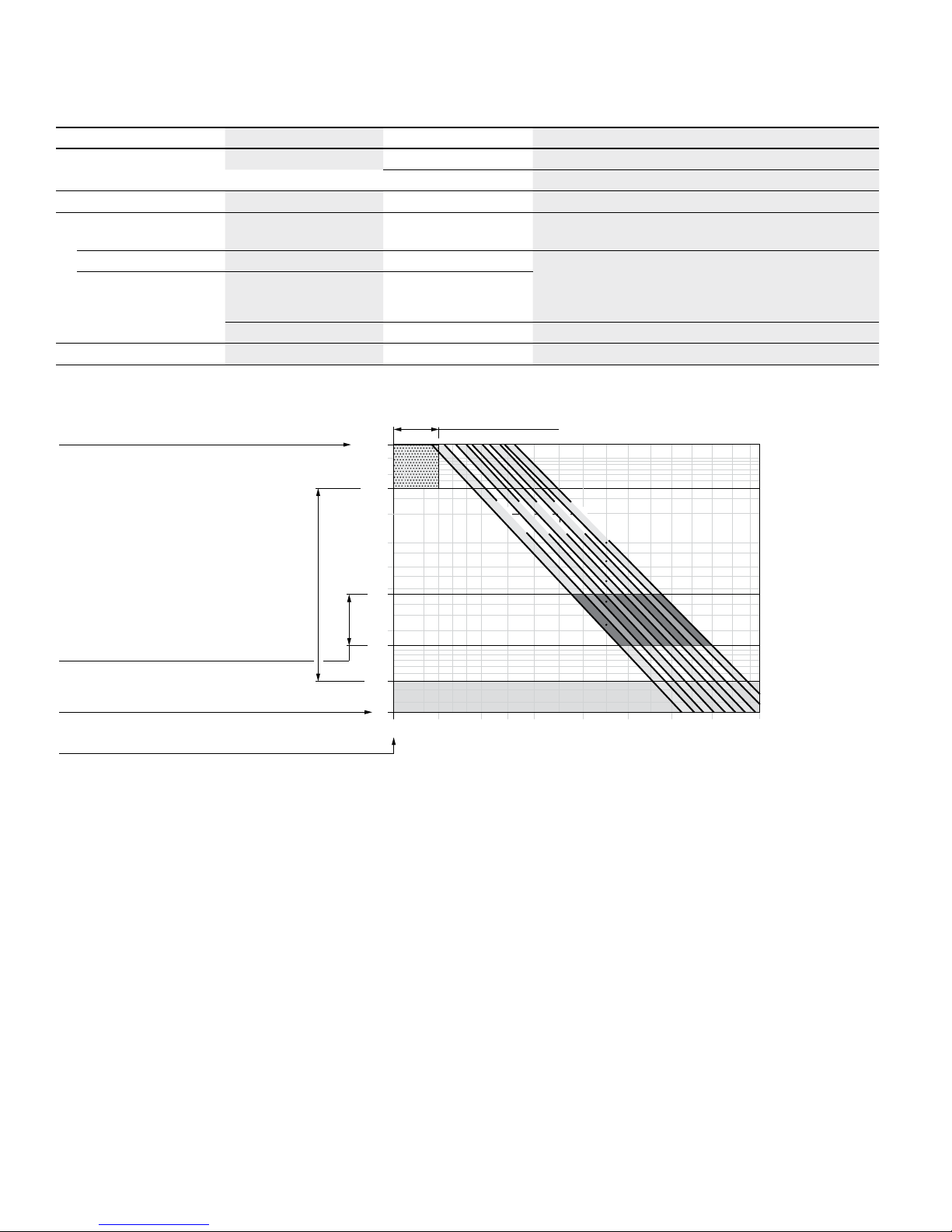
Working pressure range
Pressure at the working line ports A or B Definition
Nominal pressure p
nom
400bar absolute The nominal pressure corresponds to the maximum design pressure.
Maximum pressure p
max
450bar absolute The maximum pressure corresponds to the maximum working pressure with‑
in the single operating period. The sum of the single operating periods must
not exceed the total operating period.
Single operating period 10s
Total operating period 300h
Minimum pressure (high‑pressure side) 25bar absolute Minimum pressure at the high‑pressure side (A or B) required to prevent
damage to the axial piston unit.
Minimum pressure – pump operating
mode (inlet)
See characteristic To prevent damage to the axial piston motor in pump mode (change of high‑
pressure side with unchanged direction of rotation, e.g. when braking),
aminimum pressure must be guaranteed at the working port (inlet).
Theminimum pressure depends on the rotational speed and displacement
of the axial piston unit.
Total pressure p
Su
(pressure A + pressure B)
700bar The summation pressure is the sum of the pressures at both work ports
(A and B).
Rate of pressure change R
Amax
Maximum permissible rate of pressure build‑up and reduction during
a pressure change across the entire pressure range.
with built‑in pressure relief valve 9000bar/s
without pressure relief valve 16000bar/s
▼ Rate of pressure change R
Amax
p
nom
∆t
∆p
Time t
Pressure p
▼ Pressure definition
t
1
t
2
t
n
Single operating
period
Pressure p
Minimum pressure (high‑pressure side)
Maximum pressure p
max
Nominal pressure p
nom
Time t
Total operating period = t1 + t2 + … + t
n
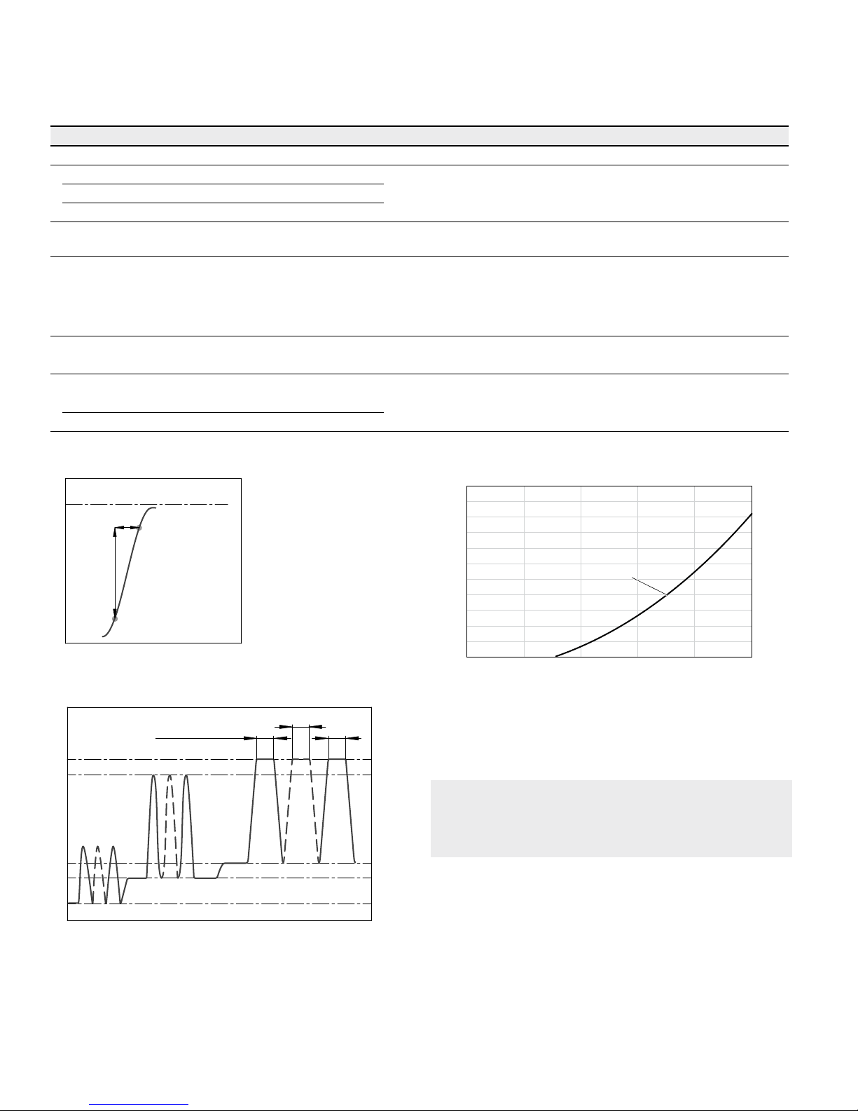
▼ Minimum pressure – pump operating mode (inlet)
Inlet pressure p
abs
[bar]
Rotational speed n / n
nom
1.00.80.60.4
0.2
0
1
2
4
6
8
10
12
V
g
This diagram is only valid for the optimum viscosity range
of ν
opt
=36 to 16mm2/s.
Please contact us if these conditions cannot be satisfied.
Note
Working pressure range valid when using hydraulic fluids
based on mineral oils. Values for other hydraulic fluids,
please contact us.

RE 91001-01-X-B2/01.2016, Bosch Rexroth AG
Axial piston fixed motor | A2FM for explosive areas
Technical data
7
Technical data
Size NG 10 12 16 23 28 32 45 56
Displacement geometric, per revolution
V
g
cm
3
10.3 12 16 22.9 28.1 32 45.6 56.1
Speed maximum
1)
Temperature class T3
n
max
rpm 8000 8000 8000 6300 6300 6300 5600 5000
Temperature class T4
n
max
rpm 4000 4000 4000 3150 3150 3150 2800 2500
Inlet flow
2)
q
v max
l/min 82 96 128 144 177 202 255 281
Torque
3)
at Δp = 350bar T
Nm 57 67 89 128 157 178 254 313
at Δp = 400bar T
Nm 66 76 102 146 179 204 290 357
Rotary stiffness
c
min
kNm/rad 0.92 1.25 1.59 2.56 2.93 3.12 4.18 5.94
Moment of inertia for rotary group
J
TW
kgm
2
0.0004 0.0004 0.0004 0.0012 0.0012 0.0012 0.0024 0.0042
Maximum angular acceleration
α
rad/s² 5000 5000 5000 6500 6500 6500 14600 7500
Case volume
V
l 0.17 0.17 0.17 0.20 0.20 0.20 0.33 0.45
Weight approx.
m
kg 5.4 5.4 5.4 9.5 9.5 9.5 13.5 18
Size NG 63 80 90 107 125 160 180
Displacement geometric, per revolution
V
g
cm
3
63 80.4 90 106.7 125 160.4 180
Speed maximum
1)
Temperature class T3
n
max
rpm 5000 4500 4500 4000 4000 3600 3600
Temperature class T4
n
max
rpm 2500 2250 2250 2000 2000 1800 1800
Inlet flow
2)
q
v max
l/min 315 362 405 427 500 577 648
Torque
3)
at Δp = 350bar T
Nm 351 448 501 594 696 893 1003
at Δp = 400bar T
Nm 401 512 573 679 796 1021 1146
Rotary stiffness
c
min
kNm/rad 6.25 8.73 9.14 11.2 11.9 17.4 18.2
Moment of inertia for rotary group
J
TW
kgm
2
0.0042 0.0072 0.0072 0.0116 0.0116 0.0220 0.0220
Maximum angular acceleration
α
rad/s² 7500 6000 6000 4500 4500 3500 3500
Case volume
V
l 0.45 0.55 0.55 0.8 0.8 1.1 1.1
Weight approx.
m
kg 18 23 23 32 32 45 45
Determining the operating characteristics
Inlet flow
q
v
=
V
g
× n
[l/min]
1000 × η
v
Rotational
speed
n
=
q
v
× 1000 × η
v
[rpm]
V
g
Torque
T
=
V
g
× Δp × η
hm
[Nm]
20 × π
Power
P
=
2 π × T × n
=
q
v
× Δp × η
t
[kW]
60000 600
Key
V
g
Displacement per revolution [cm3]
Δp
Differential pressure [bar]
n
Rotational speed [rpm]
η
v
Volumetric efficiency
η
hm
Hydraulic‑mechanical efficiency
η
t
Total efficiency (ηt = ηv × ηhm)
Note
▶ Theoretical values, without efficiency and tolerances;
values rounded.
▶ Operation above the maximum values or below the
minimum values may result in a loss of function,
areduced service life or in the destruction of the axial
piston unit. Other permissible limit values, such as
speed variation, reduced angular acceleration as a
function of the frequency and the permissible angular
acceleration at start (lower than the maximum angular
acceleration) can be found in data sheet 90261.
1) The valid values (observing the maximum permissible flow):
– for the optimum viscosity range from ν
opt
= 36 to 16 mm2/s
– with hydraulic fluid on the basis of mineral oil
2) Observe limitation of inlet flow due to counterbalance valve (see
page 24).
3)
Torque without radial force, with radial force
see page 8.
Bosch Rexroth AG, RE 91001-01-X-B2/01.2016
8 A2FM for explosive areas | Axial piston fixed motor
Technical data
Permissible radial and axial forces of the drive shafts
Size NG 10 10 12 12 16 23 23 28 28
Drive shaft Ø mm 20 25 20 25 25 25 30 25 30
Maximum radial force
1)
at distance a
(from shaft collar)
a
F
q
F
q max
kN 3.0 3.2 3.0 3.2 3.2 5.7 5.4 5.7 5.4
a mm 16 16 16 16 16 16 16 16 16
Maximum torque at F
q max
T
max
Nm 66 66 76 76 102 146 146 179 179
Maximum differential pressure at V
g max
and F
q max
Δp
max
bar 400 400 400 400 400 400 400 400 400
Maximum axial force at
standstill or pressure‑
free operation
–
+
F
ax
+F
axmax
N 0 0 0 0 0 0 0 0 0
−F
axmax
N 320 320 320 320 320 500 500 500 500
Permissible axial force per bar working pressure
+F
axperm
/bar
N/bar 3.0 3.0 3.0 3.0 3.0 5.2 5.2 5.2 5.2
Size NG 32 45 56 56
2)
56 63 80 80
2)
80
Drive shaft Ø mm 30 30 30 30 35 35 35 35 40
Maximum radial force
1)
at distance a
(from shaft collar)
a
F
q
F
q max
N 5.4 7.6 9.5 7.8 9.1 9.1 11.6 11.1 11.4
a mm 16 18 18 18 18 18 20 20 20
Maximum torque at F
q max
T
max
Nm 204 290 357 294 357 401 512 488 512
Maximum differential pressure at V
g max
and F
q max
Δp
max
bar 400 400 400 330 400 400 400 380 400
Maximum axial force at
standstill or pressure‑
free operation
–
+
F
ax
+F
axmax
N 0 0 0 0 0 0 0 0 0
−F
axmax
N 500 630 800 800 800 800 1000 1000 1000
Permissible axial force per bar working pressure
+F
axperm
/bar
N/bar 5.2 7.0 8.7 8.7 8.7 8.7 10.6 10.6 10.6
Size NG 90 107 107 125 160 160 180
Drive shaft Ø mm 40 40 45 45 45 50 50
Maximum radial force
1)
at distance a (from
shaft collar)
a
F
q
F
q max
kN 11.4 13.6 14.1 14.1 18.1 18.3 18.3
a mm 20 20 20 20 25 25 25
Maximum torque at F
q max
T
max
Nm 573 679 679 796 1021 1021 1146
Maximum differential pressureat V
g max
and F
q max
p
nom perm.
bar 400 400 400 400 400 400 400
Maximum axial force at
standstill or pressure‑
free operation
–
+
F
ax
+F
axmax
N 0 0 0 0 0 0 0
−F
axmax
N 1000 1250 1250 1250 1600 1600 1600
Permissible axial force per bar working pressure
+F
axperm
/bar
N/bar 10.6 12.9 12.9 12.9 16.7 16.7 16.7
1) With intermittent operation
2)
Restricted technical data only for splined shaft

RE 91001-01-X-B2/01.2016, Bosch Rexroth AG
Axial piston fixed motor | A2FM for explosive areas
Technical data
9
Effect of radial force F
q
on the service life of bearings
By selecting a suitable direction of radial force F
q
, the load
on the bearings, caused by the internal rotary group forces
can be reduced, thus optimizing the service life of the
bearings. Recommended position of mating gear is depen‑
dent on direction of rotation. Examples:
Gear output drive V-belt output
NG
φ
opt
φ
opt
10 to 180 ±70°
±45°
Note
▶ The permissible axial force in direction −F
ax
is to be
avoided as the lifetime of the bearing is reduced.
▶ Special requirements apply in the case of belt drives.
Please contact us.
▼ Toothed gear output drive
2
3
1
A B
φ
opt
φ
opt
1 “Counter‑clockwise” rotation. Pressure at port B
2 “Clockwise
” rotation, Pressure at port A
3 Bidirectional direction of rotation
 Loading...