

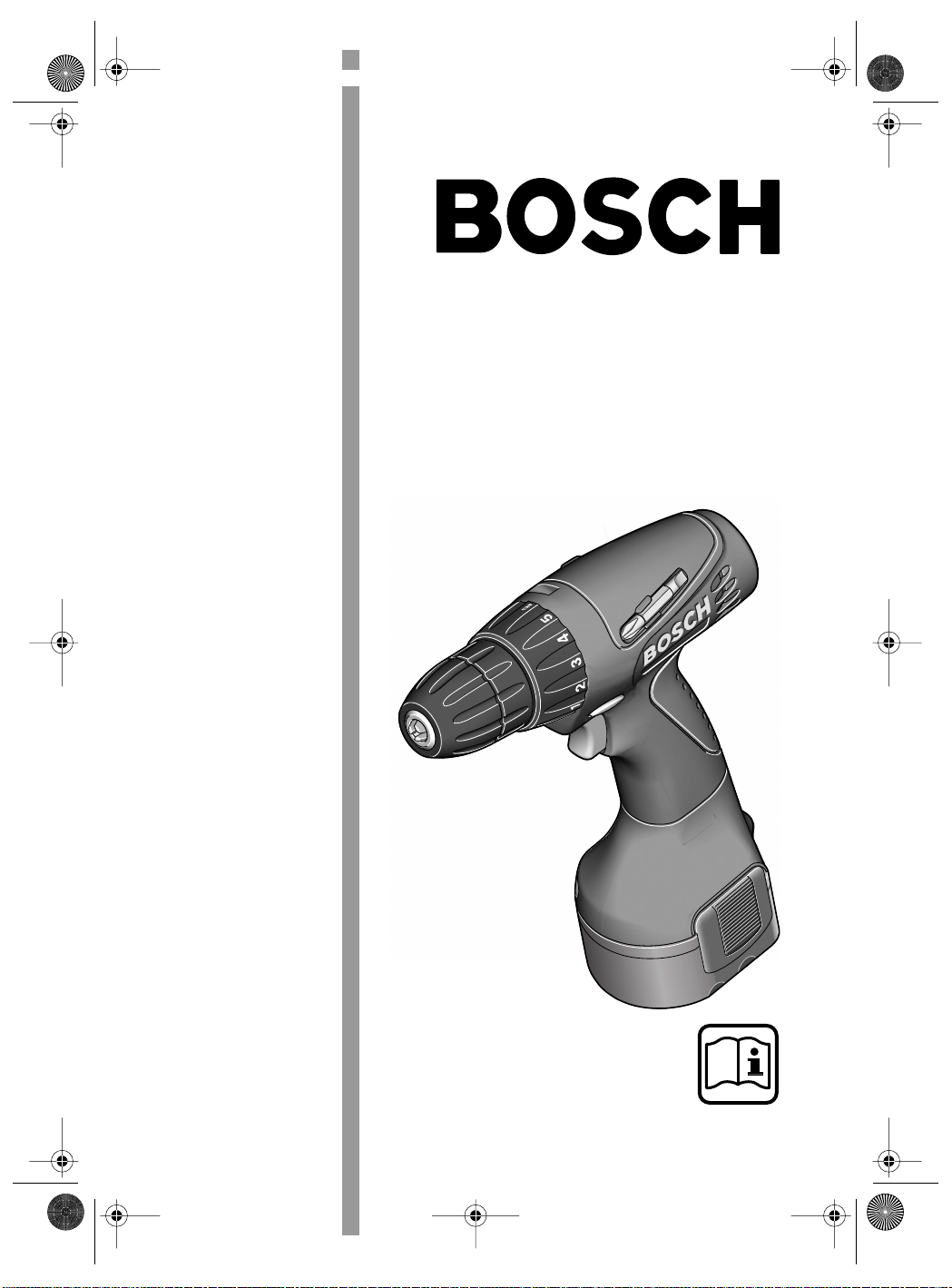
Page 1
EURO • Printed in Malaysia • BA 2 609 140 186 • PSR 960-1440 • Titel (Vorderseite) • OSW 02.02
2 609 140 186.book Seite 1 Donnerstag, 7. Februar 2002 3:14 15
Bedienungsanleitung
Operating Instructions
Instructions d’emploi
Instrucciones de servicio
Manual de instruções
Istruzioni d’uso
Gebruiksaanwijzing
Betjeningsvejledning
Bruksanvisning
Brukerveiledningen
Käyttöohje
Oδηγία χειρισµού
Kullanım kılavuzu
PSR 960
PSR 1200
PSR 1440
Deutsch
English
Français
Español
Português
Italiano
Nederlands
Dansk
Svenska
Norsk
Suomi
Eλληνικά
Türkçe
Page 2
EURO • Printed in Malaysia • BA 2 609 140 186 • PSR 960-1440 • U2 • OSW 02.02
2 609 140 186.book Seite 2 Donnerstag, 7. Februar 2002 3:14 15
1
2
3
4
7
PSR 960
PSR 1200
PSR 1440
A
7
2 • 2 609 140 186 • 02.02
6
5
B
8
7
Page 3

EURO • Printed in Malaysia • BA 2 609 140 186 • PSR 960-1440 • D • OSW 02.02
2 609 140 186.book Seite 1 Donnerstag, 7. Februar 2002 3:14 15
Gerätekennwerte
Akku-Schrauber PSR 960 PSR 1200 PSR 1440
Bestellnummer 0 603 944 6.. 0 603 944 5.. 0 603 944 4..
Leerlaufdrehzahl [min-1] 0–550 0–700 0–700
Drehmoment max. [Nm] 12 15 15
Bohr-Ø Stahl [mm] 8 10 10
Bohr-Ø Weichholz [mm] 14 20 25
Bohr-Ø Hartholz [mm] 8 10 10
Schrauben-Ø [mm] 6 8 8
Bohrspindelgewinde 3/8" 3/8" 3/8"
Gewicht mit Akku [kg] 1,3 1,4 1,5
Akku NiCd NiCd NiCd
Temperaturüberwachung NTC NTC NTC
Nennspannung [V=] 9,6 12 14,4
Gewicht [kg] 0,4 0,5 0,6
Bitte die Bestellnummer Ihrer Maschine beachten. Die Handelsbezeichnungen einzelner Maschinen können variieren.
Geräteelemente
1 Drehmoment-Einstellring
2 Schnellspannbohrfutter
3 Drehrichtungsumschalter
4 Ein-/Ausschalter
5 Akku
6 Akku-Entriegelungstaste
7 Schraubendrehereinsatz (Bit)
8 Bithalter
Abgebildetes oder beschriebenes Zubehör gehört
teilweise nicht zum Lieferumfang.
Bestimmungsgemäßer Gebrauch
Das Gerät ist bestimmt zum Eindrehen und Lösen von Schrauben sowie zum Bohren in Holz,
Metall, Keramik und Kunststoff.
Geräusch-/Vibrationsinformation
Messwerte ermittelt entsprechend EN 50 144.
Der A-bewertete Schalldruckpegel des Gerätes
ist typischerweise kleiner als 70 dB (A).
Der Geräuschpegel beim Arbeiten kann
85 dB (A) überschreiten.
Gehörschutz tragen!
Die Hand-Arm-Vibration ist typischerweise niedriger als 2,5 m/s
2
.
Zu Ihrer Sicherheit
Gefahrloses Arbeiten mit dem
Gerät ist nur möglich, wenn Sie
die Bedienungsanleitung und
die Sicherheitshinweise vollständig lesen und die darin enthaltenen Anweisungen strikt befolgen. Zusätzlich müssen die
allgemeinen Sicherheitshinweise im beigefügten Heft befolgt werden.
■ Schutzbrille tragen.
■ Bei langen Haaren Haarschutz tragen. Nur mit
enganliegender Kleidung arbeiten.
■ Vor jeder Benutzung Gerät und Akku überprüfen. Werden Schäden festgestellt, Gerät nicht
weiter benutzen. Reparatur nur von einem
Fachmann durchführen lassen. Gerät nie
selbst öffnen.
■ Die Nennspannung des Akkus muss mit den
Angaben auf dem Gerät übereinstimmen.
■ Vor allen Arbeiten an dem Gerät und bei dessen Aufbewahrung den Akku herausnehmen.
■ Vor Einsetzen des Akkus, zum Werkzeugwechsel, sowie bei Transport und Aufbewahrung den Drehrichtungsumschalter stets in
Mittelstellung bringen.
■ Überzeugen Sie sich vor der Benutzung vom
sicheren Sitz des Akkus im Gerät.
■ Das Gerät nicht so weit belasten, dass es zum
Stillstand kommt.
3 • 2 609 140 186 • TMS • 01.02.02
Deutsch - 1
Page 4
EURO • Printed in Malaysia • BA 2 609 140 186 • PSR 960-1440 • D • OSW 02.02
2 609 140 186.book Seite 2 Donnerstag, 7. Februar 2002 3:14 15
■ Gerät gut festhalten: Beim Festziehen können
kurzzeitig hohe Reaktionsmomente auftreten.
■ Niemals Kindern die Benutzung des Gerätes
gestatten.
■ Bosch kann nur dann eine einwandfreie Funktion des Gerätes zusichern, wenn das für dieses Gerät vorgesehene Original-Zubehör verwendet wird.
Akku und Ladegerät
■ Unbedingt die beiliegende Bedienungsanleitung des Ladegerätes lesen!
■ Akku und Ladegerät sind aufeinander abgestimmt. Zum Laden nur ein dafür vorgesehenes Bosch-Ladegerät mit zum Akku passender Ladespannung verwenden (siehe Typenschild). Eine Kombination mit
unterschiedlichen Nennspannungen führt zur
Beschädigung von Akku bzw. Ladegerät.
■ Erwärmten Akku vor dem Laden abkühlen lassen.
■ Akku vor Hitze und Feuer schützen: Explosionsgefahr! Akku nicht auf Heizkörper ablegen
oder längere Zeit starker Sonneneinstrahlung
aussetzen, Temperaturen über 50 °C schaden.
■ Akku nicht öffnen sowie vor Stoß schützen.
Trocken und frostsicher aufbewahren.
■ Die Kontakte des herausgezogenen Akkus abdecken. Bei Kurzschluss durch metallische
Überbrückung besteht Brandgefahr.
■ Werfen Sie den Akku nicht in den Hausmüll,
ins Feuer oder ins Wasser.
Vor der Inbetriebnahme
Akku laden
Ein neuer oder längere Zeit nicht verwendeter
Akku bringt erst nach ca. 5 Lade- und Entladezyklen seine volle Leistung.
Zur Entnahme des Akkus 5 die Entriegelungstasten 6 drücken und den Akku nach unten herausziehen. Keine Gewalt anwenden.
Der Akku ist mit einer NTC-Temperaturüberwachung ausgestattet, welche Ladung nur im Temperaturbereich zwischen 0 °C und 45 °C zulässt.
Dadurch wird eine hohe Akku-Lebensdauer erreicht.
Eine wesentlich verkürzte Betriebszeit nach der
Aufladung zeigt an, dass die Akkus verbraucht
sind und ersetzt werden müssen.
■ Hinweise zum Umweltschutz beachten.
Werkzeugwechsel
Das Bohrfutter öffnen, bis das Werkzeug eingesetzt werden kann. Das Werkzeug einsetzen.
Die hintere Hülse festhalten und die vordere
Hülse von Hand kräftig zudrehen bis kein Überrasten („klick“) mehr hörbar ist. Das Bohrfutter
wird dadurch automatisch verriegelt.
Die Verriegelung löst sich wieder, wenn zum Entfernen des Werkzeuges die vordere Hülse in Gegenrichtung gedreht wird.
Schrauben (siehe Bilder + )
Die Schrauberklinge direkt in das Bohrfutter einspannen oder bei Verwendung von Schraubendrehereinsätzen (Bits) 7 zusätzlichen Universal-
bithalter 8 verwenden.
A B
Inbetriebnahme
Akku einsetzen
Den Drehrichtungsumschalter 3 auf Mitte = Ein-
schaltsperre stellen und den geladenen Akku 5 in
den Griff einrasten lassen.
Ein-/Ausschalten
Zur Inbetriebnahme des Gerätes den Ein-/Ausschalter 4 drücken.
Die Maschine läuft je nach Druck
auf den Ein-/Ausschalter 4 mit variabler Drehzahl zwischen 0 und Maximum. Leichter Druck bewirkt eine
kleine Drehzahl und macht somit
einen sanften, kontrollierten Anlauf
möglich. Das Gerät nicht so stark
belasten, dass es zum Stillstand
kommt.
Zum Ausschalten des Gerätes den Ein-/Ausschalter 4 loslassen.
4 • 2 609 140 186 • TMS • 01.02.02
Deutsch - 2
Page 5
EURO • Printed in Malaysia • BA 2 609 140 186 • PSR 960-1440 • D • OSW 02.02
b
2 609 140 186.book Seite 3 Donnerstag, 7. Februar 2002 3:14 15
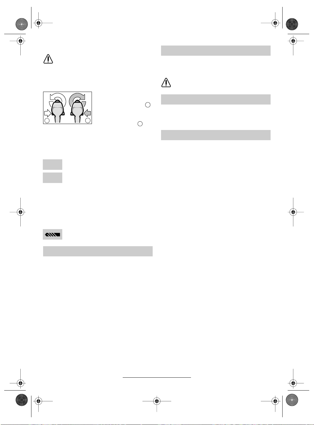
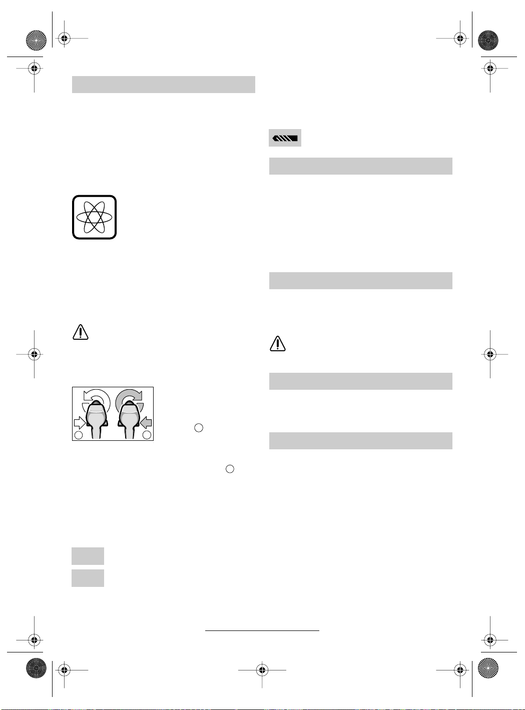
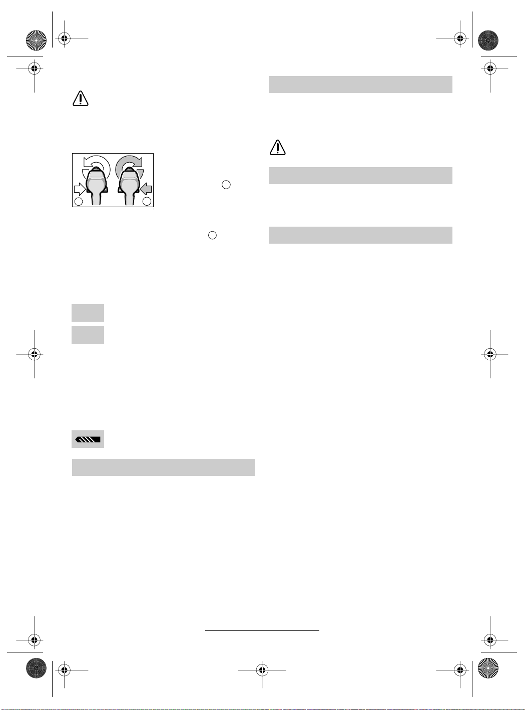
Umschalten der Drehrichtung
Den Drehrichtungsumschalter 3 nur bei
Stillstand betätigen.
Mit dem Drehrichtungsumschalter 3 wird die
Drehrichtung der Maschine umgeschaltet. Bei
betätigtem Ein-/Ausschalter 4 ist dies jedoch
nicht möglich.
Zum Bohren und Eindrehen von Schrauben ist
Drehrichtung
RECHTS einzustel-
a
len.
b
b
b
bbbb
Um Schrauben herauszudrehen, ist auf Drehrichtung LINKS umzuschalten.
b
a
Drehmoment einstellen
Im praktischen Versuch ist zu ermitteln, mit welcher der 5 Einstellungen des Drehmoment-Einstellrings 1 die Schrauben bündig in das Material
eingedreht werden.
Schwache Einstellung, z. B. kleine
1
Schrauben, weiche Werkstoffe.
Starke Einstellung, z. B. große Schrau-
5
ben, harte Werkstoffe.
Bei richtiger Einstellung öffnet die Überrastkupplung, sobald die Schraube bündig in das Material
eingedreht bzw. das eingestellte Drehmoment erreicht ist. Beim Herausdrehen höhere Einstellung
wählen, bzw. auf Symbol „Bohren“ stellen. Die
richtige Einstellung ist durch praktischen Versuch
zu ermitteln.
Bohren
Den Drehmoment-Einstellring 1 auf das
Symbol „Bohren“ stellen.
Arbeitshinweise
Auslaufbremse
Beim Loslassen des Ein-/Ausschalters 4 wird das
Bohrfutter abgebremst und dadurch das Nachlaufen des Werkzeugs verhindert.
Bei Schraubarbeiten den Ein-/Ausschalter 4 erst
dann loslassen, wenn die Schraube bündig in
das Material eingedreht ist. Der Schraubenkopf
dringt dann nicht in das Material ein.
Bohrfutter wechseln
Bei Geräten ohne Bohrspindelarretierung muss
das Bohrfutter von einer autorisierten Kundendienststelle für Bosch-Elektrowerkzeuge ausgewechselt werden.
Das Bohrfutter muss mit einem Anzugsdrehmoment von ca. 35–40 Nm festgezogen werden.
Tipps
■ Bei Eindrehen größerer, längerer Schrauben
in harten Werkstoffen am besten vorbohren.
Wartung und Reinigung
■ Vor allen Arbeiten an dem Gerät den Akku
herausnehmen.
Gerät und Lüftungsschlitze stets sauber
☞
halten, um gut und sicher zu arbeiten.
Sollte das Gerät trotz sorgfältiger Herstellungsund Prüfverfahren einmal ausfallen, ist die Reparatur von einer autorisierten Kundendienststelle
für Bosch-Elektrowerkzeuge ausführen zu lassen.
Bei allen Rückfragen und Ersatzteilbestellungen
bitte unbedingt die 10-stellige Bestellnummer laut
Typenschild des Gerätes angeben.
5 • 2 609 140 186 • TMS • 01.02.02
Deutsch - 3
Page 6
EURO • Printed in Malaysia • BA 2 609 140 186 • PSR 960-1440 • D • OSW 02.02
2 609 140 186.book Seite 4 Donnerstag, 7. Februar 2002 3:14 15
Umweltschutz Service und Kundenberater
www.bosch-pt.com
www.powertool-portal.de, das Internetportal
für Heimwerker und Gartenfreunde
www.dha.de, das komplette Service-Angebot
der Deutschen Heimwerker Akademie
Rohstoffrückgewinnung statt Müllentsorgung
Gerät, Zubehör und Verpackung sollten einer
umweltgerechten Wiederverwertung zugeführt
werden.
Diese Anleitung ist aus chlorfrei gefertigtem Recycling-Papier hergestellt.
Zum sortenreinen Recycling sind Kunststoffteile
gekennzeichnet.
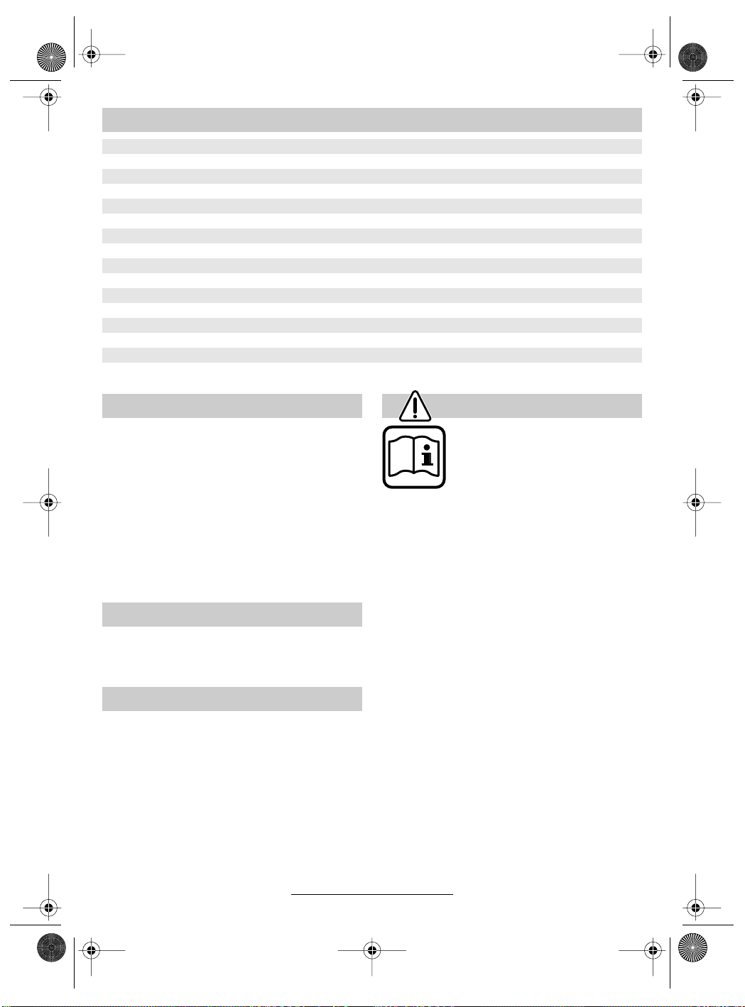
Nickel-Cadmium-Akku:
Wenn Ihr Produkt mit einem Nickel-CadmiumAkku ausgerüstet ist,
muss der Akku gesammelt, recycelt oder auf
umweltfreundliche Weise
entsorgt werden.
Defekte oder verbrauchte Akkus müssen gemäß
Richtlinie 91/157/EWG recycelt werden.
Nicht mehr gebrauchsfähige Akkus/Batterien
können direkt abgegeben werden bei:
Deutschland
Recyclingzentrum Elektrowerkzeuge
Osteroder Landstraße 3
37589 Kalefeld
Schweiz
Batrec AG
3752 Wimmis BE
In Deutschland sind nicht mehr gebrauchsfähige
Geräte zum Recycling beim Handel abzugeben
oder (ausreichend frankiert) direkt einzuschicken
an:
Recyclingzentrum Elektrowerkzeuge
Osteroder Landstraße 3
37589 Kalefeld
Deutschland
Robert Bosch GmbH
Servicezentrum Elektrowerkzeuge
Zur Luhne 2
D-37589 Kalefeld
✆ Service:....................................... 01 80 - 3 35 54 99
............................................. +49 (0) 55 53 / 20 22 37
Fax
✆ Kundenberater: ...................... 01 80 - 3 33 57 99
Österreich
ABE Service GmbH
Jochen-Rindt-Straße 1
A-1232 Wien
✆ Service:..................................... +43 (0)1 / 61 03 80
................................................. +43 (0)1 / 61 03 84 91
Fax
✆ Kundenberater:............ +43 (0)1 / 797 22 3066
E-Mail: abe@abe-service.co.at
Schweiz
Robert Bosch AG
Kundendienst Elektrowerkzeuge
Industriestrasse 31
CH-8112 Otelfingen
✆ Service:................................. +41 (0)1 / 8 47 16 16
✆ Kundenberater:...... Grüne Nr. 0 800 55 11 55
Konformitätserklärung
Wir erklären in alleiniger Verantwortung, dass dieses Produkt mit den folgenden Normen oder normativen Dokumenten übereinstimmt: EN 50 144
(Akku-Geräte) bzw. EN 60 335 (Akku-Ladegeräte) gemäß den Bestimmungen der Richtlinien
73/23/EWG, 89/336/EWG, 98/37/EG.
02
Dr. Gerhard Felten Dr. Eckerhard Strötgen
6 • 2 609 140 186 • TMS • 01.02.02
Robert Bosch GmbH, Geschäftsbereich Elektrowerkzeuge
Änderungen vorbehalten
Deutsch - 4
Page 7
EURO • Printed in Malaysia • BA 2 609 140 186 • PSR 960-1440 • GB • OSW 02.02
2 609 140 186.book Seite 1 Donnerstag, 7. Februar 2002 3:14 15
Tool Specifications
Cordless Screwdriver PSR 960 PSR 1200 PSR 1440
Order number 0 603 944 6.. 0 603 944 5.. 0 603 944 4..
No-load speed [rpm] 0–550 0–700 0–700
Torque max. [Nm] 12 15 15
Drill dia. steel [mm] 8 10 10
Drilling-Ø softwood [mm] 14 20 25
Drilling-Ø hardwood [mm] 8 10 10
Screw diameter [mm] 6 8 8
Drill spindle thread 3/8" 3/8" 3/8"
Weight with battery [kg] 1.3 1.4 1.5
Battery NiCd NiCd NiCd
Temperature control NTC NTC NTC
Rated voltage [V=] 9.6 12 14.4
Weight [kg] 0.4 0.5 0.6
Please observe the order number of your machine. The trade names of the individual machines may vary.
Machine Elements
1 Torque setting ring
2 Keyless chuck
3 Rotational direction switch
4 On/Off switch
5 Battery
6 Battery unlocking button
7 Screwdriver attachment (bit)
8 Bit holder
Not all of the accessories illustrated or described are
included as standard delivery.
Intended Use
The machine is intended for the screwing in and
loosening of screws as well as for drilling in wood,
metal, ceramic and plastic.
Noise/Vibration Information
Measured values determined according to
EN 50 144.
Typically the A-weighted sound pressure level of
the product is less than 70 dB (A).
The noise level when working can exceed
85 dB (A).
Wear ear protection!
The typical hand/arm vibration is below 2.5 m/s
For Your Safety
Working safely with this machine is possible only when the
operating and safety information
are read completely and the instructions contained therein are
strictly followed. In addition, the
general safety notes in the enclosed booklet must be observed.
■ Wear safety goggles.
■ For long hair, wear hair protection. Work only
with closely fitting clothes.
■ Before each use, check the machine and battery. If damage is detected, do not use the machine. Have repairs performed only by a qualified technician. Never open the machine yourself.
■ The rated voltage of the battery must agree
with the data on the machine.
■ Remove the battery before any work on the
machine itself and before storing it.
■ Before inserting the battery, when changing
tools as well as when transporting and storing,
always set the rotational direction switch to the
centre position!
■ Convince yourself before using that the battery
2
is securely seated in the machine.
.
■ Do not strain the machine so heavily that it
comes to a standstill.
7 • 2 609 140 186 • TMS • 01.02.02
English - 1
Page 8
EURO • Printed in Malaysia • BA 2 609 140 186 • PSR 960-1440 • GB • OSW 02.02
2 609 140 186.book Seite 2 Donnerstag, 7. Februar 2002 3:14 15
■ Hold the machine tightly: When driving in
screws, high reaction moments can briefly occur.
■ Never allow children to use the machine.
■ Bosch is only able to ensure perfect operation
of the machine if the original accessories intended for it are used.
Battery and Battery Charger
■ The enclosed operating instructions for the
battery charger must be read carefully!
■ The battery and battery charger are designed
to match each other. When charging the battery, use only a Bosch battery charger designed for it with a charging voltage that corresponds with the battery (see type plate). Combining different rated voltages causes damage
to the battery charger.
■ Allow a heated battery to cool before charging.
■ Protect the battery from heat and fire: Danger
of explosion! Do not place the battery on radiators or expose to strong sun rays for a longer
time; temperatures over 50 °C cause damage.
■ Do not open the battery, and protect it from impact. Store in a dry and frost-free place.
■ Cover the contacts of a removed battery. Danger of fire results when shorted by a metal object!
■ Do not throw the battery into the household
waste, into fire or water.
Before Putting into Operation
Battery Charging
A battery that is new or has not been used for a
longer period does not develop its full capacity
until after approximately 5 charging/discharging
cycles.
To remove the battery 5, press the unlocking buttons 6 and pull out the battery downwards. Do not
exert any force.
The battery is equipped with an NTC temperature
control which allows charging only within a temperature range of between 0 °C and 45 °C.
A long battery service life is achieved in this manner.
A significantly reduced working period after
charging indicates that the batteries are used and
must be replaced.
■ Observe the notes on environmental protection.
Changing the Tool
Open the drill chuck until the tool can be inserted.
Insert the tool.
Hold the rear collar tight and firmly tighten the
front collar by hand, until the “clicking” of the locking action is no longer heard. This automatically
locks the chuck.
The locking is released again when the front collar is turned in the opposite direction to remove
the tool.
Screwdriving (see figures + )
Directly clamp the screwdriver bit into the drill
chuck or use the additional universal bit holder 8
when operating with hex shank bits 7.
A B
Initial Operation
Inserting the Battery
Set the rotational direction switch 3 to the centre
position = lock-off and allow the charged battery 5 to engage into the handle.
Switching On and Off
To start the machine press the On/Off switch 4.
The machine runs with variable
speed between 0 and maximum,
depending on the pressure applied
to the On / Off switch 4. Light pres-
sure results in a low rotational
speed thus allowing smooth, controlled starts. Do not strain the machine so heavily that it comes to a
standstill.
To switch off the machine, release the On / Off
switch 4.
8 • 2 609 140 186 • TMS • 01.02.02
English - 2
Page 9
EURO • Printed in Malaysia • BA 2 609 140 186 • PSR 960-1440 • GB • OSW 02.02
b
2 609 140 186.book Seite 3 Donnerstag, 7. Februar 2002 3:14 15
Reversing the Rotational Directions
Operate the rotational direction
switch 3 only at a standstill.
The rotational direction switch 3 is used to re-
verse the rotational direction of the machine.
However, this is not possible with the On/Off
switch 4 actuated.
For drilling and driving in
screws, set the rotational
direction CLOCKWISE .
To drive out screws, switch
a
to the rotational direction
b
b
b
bbbb
ANTICLOCKWISE .
b
a
Setting the Torque
Carry out a practical test to determine with which
of the 5 settings of the torque setting ring 1 the
screws are driven flush into the material.
Low setting, e. g., small screws, soft
1
materials.
High setting, e. g., large screws, hard
5
materials.
With the correct setting, the clutch disengages as
soon as the screw is driven flush into the material
or the set torque is reached. Select a higher setting when driving out screws, or set to the “Drilling” symbol. The correct setting is to be determined by practical testing.
Drilling
Set the torque setting ring 1 to the “Drilling” symbol.
Replacing the Drill Chuck
For machines without a drill spindle locking facility, the chuck must be changed by an authorised
after-sales service shop for Bosch power tools.
The chuck must be tightened with a
torque of approx. 35–40 Nm.
Tips
■ It is advisable to first drill a pilot hole before attempting to screw in large, long screws in hard
material.
Maintenance and Cleaning
■ Before any work on the machine itself, remove the battery.
For safe and proper working, always keep
☞
the machine and the ventilation slots clean.
If the machine should fail despite the care taken
in manufacturing and testing procedures, repair
should be carried out by an after-sales service
centre for Bosch power tools.
In all correspondence and spare parts orders,
please always include the 10-digit order number
given on the nameplate of the machine.
Operating Instructions
Run-On Brake
When releasing the On/Off switch 4 the speed of
the drill chuck is reduced to a stop, thus preventing the run-on of the tool.
For screwdriving applications, wait until the screw
is flush with the material and then release the
On/Off switch 4. The screw head does not penetrate into the material then.
9 • 2 609 140 186 • TMS • 01.02.02
English - 3
Page 10
EURO • Printed in Malaysia • BA 2 609 140 186 • PSR 960-1440 • GB • OSW 02.02
2 609 140 186.book Seite 4 Donnerstag, 7. Februar 2002 3:14 15
Environmental Protection Service and
Customer Assistance
www.bosch-pt.com
Great Britain
Robert Bosch Ltd. (B.S.C.)
P.O. Box 98
Recycle raw materials instead of disposing as
waste.
The machine, accessories and packaging should
be sorted for environmental-friendly recycling.
These instructions are printed on recycled paper
manufactured without chlorine.
The plastic components are labelled for categorized recycling.
Nickel-cadmium-battery:
If your product is equipped
with a nickel-cadmium-battery, the battery must be
collected, recycled or disposed of in an environmentally-friendly way.
Defective or worn out batteries must be recycled
according to the guidelines 91/157/EEC.
Batteries no longer suitable for use can be
directly returned at:
Great Britain
Robert Bosch Ltd. (B.S.C.)
P.O. Box 98
Broadwater Park
North Orbital Road
Denham-Uxbridge
GB-Middlesex UB 9 5HJ
✆ Service............................ +44 (0)18 95 / 83 87 82
✆ Advice line.................... +44 (0)18 95 / 83 87 91
............................................. +44 (0)18 95 / 83 87 89
Fax
Broadwater Park
North Orbital Road
Denham-Uxbridge
GB-Middlesex UB 9 5HJ
✆ Service............................ +44 (0)18 95 / 83 87 82
✆ Advice line.................... +44 (0)18 95 / 83 87 91
............................................. +44 (0) 18 95 / 83 87 89
Fax
Ireland
Beaver Distribution Ltd.
Greenhills Road
IRL-Tallaght-Dublin 24
✆ Service................................... +353 (0)1 / 414 9400
.................................................... +353 (0)1 / 459 8030
Fax
Australia
Robert Bosch Australia L.t.d.
RBAU/SPT2
1555 Centre Road
P.O. Box 66 Clayton
AUS-3168 Clayton/Victoria
✆ ............................................... +61 (0)1 / 800 804 777
............................................... +61 (0)1 / 800 819 520
Fax
www.bosch.com.au
E-Mail: CustomerSupportSPT@au.bosch.com
New Zealand
Robert Bosch Limited
14-16 Constellation Drive
Mairangi Bay
Auckland
New Zealand
✆ ..................................................... +64 (0)9 / 47 86 158
Fax
..................................................... +64 (0)9 / 47 82 914
10 • 2 609 140 186 • TMS • 01.02.02
Declaration of Conformity
We declare under our sole responsibility that this
product is in conformity with the following standards or standardization documents. EN 50 144
(Battery powered products) and EN 60 335 (Battery charger) according to the provisions of the directives 73/23/EEC, 89/336/EEC, 98/37/EC.
02
Dr. Gerhard Felten Dr. Eckerhard Strötgen
Robert Bosch GmbH, Geschäftsbereich Elektrowerkzeuge
Subject to change without notice
English - 4
Page 11
EURO • Printed in Malaysia • BA 2 609 140 186 • PSR 960-1440 • F • OSW 02.02
2 609 140 186.book Seite 1 Donnerstag, 7. Februar 2002 3:14 15
Caractéristiques techniques
Perceuse sans fil PSR 960 PSR 1200 PSR 1440
Référence 0 603 944 6.. 0 603 944 5.. 0 603 944 4..
Régime à vide [tr/min] 0–550 0–700 0–700
Couple max. [Nm] 12 15 15
Ø perçage dans l’acier [mm] 8 10 10
Ø perçage dans bois tendre [mm] 14 20 25
Ø perçage dans bois dur [mm] 8 10 10
Ø des vis [mm] 6 8 8
Fixation de la broche 3/8" 3/8" 3/8"
Poids avec accumulateur [kg] 1,3 1,4 1,5
Accumulateur NiCd NiCd NiCd
Contrôle de température NTC NTC NTC
Tension nominale [V=] 9,6 12 14,4
Poids [kg] 0,4 0,5 0,6
Faire attention au numéro de référence de la machine. Les désignations commerciales des différentes machines peuvent
varier.
Eléments de la machine
1 Bague de réglage du couple
2 Mandrin à serrage rapide
3 Commutateur du sens de rotation
4 Interrupteur Marche/Arrêt
5 Accumulateur
6 Touche de déverrouillage de l’accumulateur
7 Embout tournevis
8 Logement pour mèche
Les accessoires reproduits ou décrits ne sont pas
forcément fournis avec la machine.
Utilisation conformément à la
destination de l’appareil
L’appareil est conçu pour le vissage et le dévissage des vis ainsi que pour le perçage dans le
bois, le métal, le céramique et les matières plastiques.
Bruits et vibrations
Valeurs de mesure obtenues conformément à la
norme européenne 50 144.
La mesure réelle (A) du niveau sonore de l’outil
est inférieure à 70 dB (A).
Le niveau sonore en fonctionnement peut dépasser 85 dB (A).
Munissez-vous d’une protection acoustique!
La vibration de l’avant-bras est en-dessous de
2
2,5 m/s
.
Pour votre sécurité
Pour travailler sans risque avec
cet appareil, lire intégralement
au préalable les instructions
d’utilisation et les remarques
concernant la sécurité. Respecter scrupuleusement les indications et les consignes qui y sont
données. Respecter en plus les
indications générales de sécurité se trouvant dans le cahier
ci-joint.
■ Porter des lunettes de protection.
■ Les personnes portant les cheveux longs doi-
vent se munir d’un protège-cheveux. Ne travailler qu’avec des vêtements près du corps.
■ Avant chaque utilisation, vérifier l’appareil et
l’accumulateur. Ne jamais mettre en marche
un appareil endommagé. Les réparations ne
doivent être confiées qu’à un spécialiste. Ne
jamais ouvrir l’appareil soi-même.
■ La tension nominale de l’accumulateur doit
correspondre aux indications figurant sur l’appareil.
■ Avant d’effectuer des travaux sur l’appareil ou
avant de le stocker, retirer l’accumulateur de
l’appareil.
11 • 2 609 140 186 • TMS • 01.02.02
Français - 1
Page 12
EURO • Printed in Malaysia • BA 2 609 140 186 • PSR 960-1440 • F • OSW 02.02
2 609 140 186.book Seite 2 Donnerstag, 7. Februar 2002 3:14 15
■ Avant de remonter l’accumulateur dans l’appareil (à l’occasion d’un changement d’outil,
après un transport ou une période de non utilisation de l’appareil, par exemple), toujours
mettre le commutateur du sens de rotation en
position médiane !
■ Avant utilisation, toujours contrôler que l’accumulateur est correctement en place.
■ Ne jamais charger l’appareil jusqu’à provoquer
son arrêt complet.
■ Bien tenir la machine: Lors du vissage, il peut
y avoir des couples de réaction élevés.
■ Ne jamais permettre aux enfants d’utiliser cet
appareil.
■ Bosch ne peut garantir un fonctionnement impeccable que si les accessoires Bosch d’origine prévus pour cet appareil sont utilisés.
Accumulateur et chargeur
■ Lire absolument le mode d’emploi du chargeur ci-joint !
■ L’accumulateur et le chargeur sont ajustés l’un
à l’autre. Pour recharger l’accumulateur, n’utiliser qu’un chargeur Bosch prévu à cet effet
avec la tension de charge adaptée à l’accumulateur (voir plaque signalétique). Une combinaison de différentes tensions nominales entraîne un endommagement de l’accumulateur
ou du chargeur.
■ Avant de recharger un accumulateur échauffé,
le laisser refroidir.
■ Protéger l’accumulateur contre toute exposition à la chaleur ou au feu : risque d’explosion ! Ne pas poser l’accumulateur sur un
corps chaud (radiateur, par exemple). Ne pas
l’exposer trop longtemps à un fort ensoleillement. Les températures dépassant 50 °C lui
sont néfastes.
■ Ne pas ouvrir l’accumulateur. Le protéger de
tout choc mécanique. L’entreposer dans un
endroit sec et à l’abri du gel.
■ Lorsque l’accumulateur est sorti de l’appareil,
protéger les contacts (au moyen d’une bande
de matériau isolant par exemple). Le shuntage
de ces deux contacts (contact accidentel avec
une autre pièce métallique) peut provoquer un
incendie !
■ Ne pas jeter l’accu dans les ordures ménagères, ni dans les flammes ou dans l’eau.
Avant la mise en service
Recharge de l’accumulateur
Un accu neuf ou un accu qui n’a pas été utilisé
pour une période assez longue n’atteint sa pleine
puissance qu’après environ cinq cycles de
charge et de décharge.
Pour sortir l’accumulateur 5, appuyer sur les boutons de déverrouillage 6 et retirer l’accumulateur
vers le bas. Ne pas forcer.
L’accumulateur est doté d’un dispositif de surveillance de la température NTC ne permettant la
charge que dans une plage de température comprise entre 0 °C et 45 °C. La longévité de l’accumulateur s’en trouve ainsi accrue.
Si le temps de service des accus se raccourcit
considérablement après un processus de
charge, cela indique que les accus sont usés et
qu’ils doivent être remplacés.
■ Observer les consignes relatives à la protection de l’environnement.
Changement de l’outil
Ouvrir le mandrin de perçage de sorte que l’outil
puisse être monté. Monter l’outil.
Tenir la douille arrière et bien visser la douille
avant en la tournant fortement à la main jusqu’à
ce qu’il n’y ait plus de déclic perceptible. Le mandrin de perçage se trouve alors verrouillé automatiquement.
Pour déverrouiller et pour pouvoir ainsi enlever
l’outil, tourner dans le sens contraire la douille
avant.
Vissage (voir figures + )
Serrer les lames de tournevis directement dans
le mandrin de perçage ou en cas d’utilisation
d’embouts tournevis (bits) 7, utiliser en plus un
porte-embout universel 8.
A B
12 • 2 609 140 186 • TMS • 01.02.02
Français - 2
Page 13
EURO • Printed in Malaysia • BA 2 609 140 186 • PSR 960-1440 • F • OSW 02.02
b
2 609 140 186.book Seite 3 Donnerstag, 7. Februar 2002 3:14 15
Mise en service
Mise en place de l’accumulateur
Mettre le commutateur du sens de rotation 3
dans la position médiane = verrouillage de mise
en fonctionnement et faire encliqueter l’accu
chargé 5 dans la poignée.
Mise en fonctionnement/Arrêt
Afin de mettre l’appareil en fonctionnement,
appuyer sur l’interrupteur Marche/Arrêt 4.
En fonction de la pression exercée
sur l’interrupteur Marche/Arrêt 4,
l’appareil fonctionne à une vitesse
comprise entre 0 et le maximum.
Une légère pression fait tourner
l’appareil à petite vitesse, ce qui
permet un démarrage précis et en
douceur. Ne pas trop solliciter l’appareil qui risque sinon de s’arrêter.
Afin d’arrêter l’appareil, relâcher l’interrupteur
Marche/Arrêt 4.
Inversion du sens de rotation
N’actionner le commutateur du sens de
rotation 3 qu’à l’arrêt total de l’appareil.
Le sens de rotation de l’appareil peut être modifié
à l’aide du commutateur du sens de rotation 3.
Cela n’est toutefois pas possible en actionnant
l’interrupteur Marche/Arrêt 4.
Pour percer et visser des
vis, le commutateur du
sens de rotation doit être
enfoncé vers la
a
DROITE .
b
b
b
bbbb
Pour dévisser des vis, il
faut enfoncer le commutateur du sens de rotation
vers la GAUCHE .
b
a
Réglage du couple
En effectuant des essais pratiques, déterminer le
réglage approprié parmi les 5 positions possibles
de la bague de réglage du couple 1 afin de pouvoir visser correctement les vis afin que leur tête
affleure le matériau.
Couple réduit p. ex. petites vis, matéri-
1
aux tendres.
Couple élevé p. ex. grandes vis, maté-
5
riaux durs.
Le réglage est correct lorsque l’embrayage à
crans est déclenché dès que la tête de la vis affleure le matériau ou que le couple préréglé est
atteint. Pour dévisser, choisir un réglage plus
élevé, ou régler sur le symbole « Perçage ». Le
réglage correct doit être déterminé par des essais pratiques.
Perçage
Positionner la bague de réglage du couple 1 sur le symbole « Perçage ».
Instructions d’utilisation
Frein de ralentissement
Lorsqu’on relâche l’interrupteur Marche/Arrêt 4,
le mandrin est freiné, ce qui évite un fonctionnement par inertie de l’outil.
Lors de travaux de vissage, ne relâcher l’interrupteur Marche/Arrêt 4 que lorsque la vis est enfoncée à ras dans le matériau. La tête de vis ne pénètre alors pas le matériau.
Changement du mandrin
Dans les appareils sans blocage de la broche de
perçage, le mandrin de perçage doit être remplacé par une station autorisée de service aprèsvente pour outillages électroportatifs Bosch.
Le mandrin de perçage doit être serré à
un couple de serrage de 35–40 Nm environ.
Conseils d’utilisation
■ Lors du vissage de vis de taille et de longueur
importantes dans des matériaux durs, il est recommandé de percer un avant-trou.
Nettoyage et entretien
■ Avant toute intervention sur l’appareil proprement dit, retirer l’accumulateur.
Pour obtenir un travail sûr et satisfaisant,
☞
nettoyer régulièrement l’appareil ainsi que
ses ouïes de refroidissement.
Si, malgré tous les soins apportés à la fabrication
et au contrôle de l’appareil, celui-ci devait avoir
un défaut, la réparation ne doit être confiée qu’à
une station de service après-vente agréée pour
outillage Bosch.
Pour toute demande de renseignements ou commande de pièces de rechange, nous préciser impérativement le numéro de référence à dix chiffres de la machine.
13 • 2 609 140 186 • TMS • 01.02.02
Français - 3
Page 14
EURO • Printed in Malaysia • BA 2 609 140 186 • PSR 960-1440 • F • OSW 02.02
2 609 140 186.book Seite 4 Donnerstag, 7. Februar 2002 3:14 15
Instructions de protection de
l’environnement
Récupération des matières premières plutôt
qu’élimination des déchets
Les machines, comme d’ailleurs leurs accessoires et emballages, doivent pouvoir suivre chacune une voie de recyclage appropriée.
Ce manuel d’instructions a été fabriqué à partir
d’un papier recyclé blanchi en l’absence de
chlore.
Nos pièces plastiques ont ainsi été marquées en
vue d’un recyclage sélectif des différents matériaux.
Accumulateur NickelCadmium : Au cas où vo-
tre produit serait équipé
d’un accu Nickel-Cadmium, l’accu doit être ré-
cupéré, recyclé ou éliminé
en conformité avec les réglementations se rapportant à l’environnement.
Les accus usés ou défectueux doivent être recyclés conformément à la directive 91/157/CEE.
Les accus /piles dont on ne peut plus se servir
peuvent être déposés directement auprès de :
Suisse
Batrec AG
3752 Wimmis BE
Service Après-Vente
www.bosch-pt.com
France
Information par Minitel 11
Nom : Bosch Outillage
Loc : Saint Ouen
Dépt : 93
Robert Bosch France S.A.
Service Après-vente/Outillage
B.P. 67-50, Rue Ardoin
F-93402 St. Ouen Cedex
✆ Service conseil client,
Numéro Vert
Belgique
Robert Bosch S.A.
After Sales Service Outillage
Rue Henri Genesse 1
BE-1070 Bruxelles
.................................... 0 800 05 50 51
✆ ..................................................... +32 (0)2 / 525.50.29
..................................................... +32 (0)2 / 525.54.30
Fax
✆ Service conseil client..... +32 (0)2 / 525.53.07
E-Mail : Outillage.Gereedschappen@be.bosch.com
Suisse
Robert Bosch AG
Service après-vente/Outillage
Industriestrasse 31
CH-8112 Otelfingen
✆ .................................................... +41 (0)1 / 8 47 16 16
✆ Service conseil client,
Numéro Vert
.................................... 0 800 55 11 55
14 • 2 609 140 186 • TMS • 01.02.02
Déclaration de conformité
Nous déclarons sous notre propre responsabilité
que ce produit est en conformité avec les normes
ou documents normalisés : EN 50 144 (appareils
sans fil) respectivement EN 60 335 (chargeurs
électriques) conformément aux termes des réglementations 73/23/CEE, 89/336/CEE, 98/37/CE.
02
Dr. Gerhard Felten Dr. Eckerhard Strötgen
Robert Bosch GmbH, Geschäftsbereich Elektrowerkzeuge
Sous réserve de modifications
Français - 4
Page 15

EURO • Printed in Malaysia • BA 2 609 140 186 • PSR 960-1440 • E • OSW 02.02
2 609 140 186.book Seite 1 Donnerstag, 7. Februar 2002 3:14 15
Características técnicas
Atornilladora con acumulador PSR 960 PSR 1200 PSR 1440
Número de pedido 0 603 944 6.. 0 603 944 5.. 0 603 944 4..
Revoluciones en vacío [min-1] 0–550 0–700 0–700
Par de giro máx. [Nm] 12 15 15
Ø taladro en acero [mm] 8 10 10
Ø de perforación en madera blanda [mm] 14 20 25
Ø de perforación en madera dura [mm] 8 10 10
Ø de tornillo [mm] 6 8 8
Rosca del husillo de la broca 3/8" 3/8" 3/8"
Peso con acumulador [kg] 1,3 1,4 1,5
Acumulador NiCd NiCd NiCd
Control de temperatura NTC NTC NTC
Tensión nominal [V=] 9,6 12 14,4
Peso [kg] 0,4 0,5 0,6
Preste atención al nº de pedido de su máquina. Las denominaciones comerciales en ciertas máquinas puede variar.
Elementos del aparato
1 Anillo de ajuste de par
2 Portabrocas de sujeción rápida
3 Selector de sentido de giro
4 Interruptor de conexión/desconexión
5 Acumulador
6 Tecla de desenclavamiento del acumulador
7 Lámina de destornillador (bit)
8 Portaláminas de destornillador
¡Los accesorios descritos e ilustrados no corresponden en parte al material que se adjunta!
Utilización reglamentaria
El aparato ha sido proyectado para enroscar y
aflojar tornillos, así como para taladrar en madera, metal, cerámica y materiales sintéticos.
Información sobre ruidos y
vibraciones
Determinación de los valores de medición según
norma EN 50 144.
El nivel de presión de sonido, típico, medido con
un filtro tipo A, es normalmente menor de
70 dB (A).
El nivel de ruido, con la máquina trabajando, podrá sobrepasar circunstancialmente 85 dB (A).
¡Usar protectores auditivos!
El nivel de vibraciones típico en la mano/brazo es
menor de 2,5 m/s
2
.
Para su seguridad
Solamente puede trabajar sin peligro con el aparato si lee íntegramente las instrucciones de
manejo y las indicaciones de seguridad, ateniéndose estrictamente a las recomendaciones
allí comprendidas. Adicionalmente deberán respetarse las
instrucciones de seguridad generales comprendidas en el folleto adjunto.
■ Ponerse unas gafas de protección.
■ Si tiene el pelo largo, recójaselo bajo una pro-
tección adecuada. Trabajar únicamente con
vestimenta ceñida al cuerpo.
■ Antes de cada utilización controlar el aparato
y el acumulador. En caso de detectar algun
daño, no continuar usando el aparato. Hacerlo
reparar solamente por personal técnico especializado. No abrir jamás el aparato por su propia cuenta.
■ La tensión nominal del acumulador debe coincidir con las indicaciones del aparato.
■ Antes de manipular en el aparato, y al guardarlo, desmontar el acumulador.
■ Antes de la inserción del acumulador, al cambiar de útil, así como al transportarlo y guardarlo, colocar el selector de sentido de giro en
su posición central.
■ Asegúrese antes de su utilización que el acumulador esté firmemente sujeto en el aparato.
15 • 2 609 140 186 • TMS • 01.02.02
Español - 1
Page 16
EURO • Printed in Malaysia • BA 2 609 140 186 • PSR 960-1440 • E • OSW 02.02
A
2 609 140 186.book Seite 2 Donnerstag, 7. Februar 2002 3:14 15
■ No solicite el aparato de manera tal que llegue
a detenerse.
■ Sujetar el aparato firmemente: al trabajar pueden presentarse brevemente unos pares de
reacción elevados.
■ Jamás permita que los niños utilicen el aparato.
■ Bosch solamente puede garantizar el funcionamiento correcto del aparato si se utilizan los
accesorios originales previstos.
Acumulador y cargador
■ ¡Es imprescindible leer las instrucciones
de manejo del cargador que se adjuntan!
■ El acumulador y el cargador han sido adaptados mutuamente. Para cargar el acumulador
debe utilizarse solamente el cargador Bosch
previsto para ello con la tensión de carga respectiva (ver placa de características). En caso
de combinar acumuladores y cargadores para
tensiones nominales diferentes éstos pueden
dañarse.
■ Dejar enfriar un acumulador caliente antes de
cargarlo.
■ Proteger el acumulador del calor y del fuego:
¡Peligro de explosión! No depositar el acumulador sobre radiadores ni exponerlo durante
tiempo prolongado al sol; las temperaturas por
encima de los 50 °C pueden dañarlo.
■ No abrir el acumulador, y protegerlo contra
golpes. Guardarlo en un lugar seco y libre de
heladas.
■ Proteger los contactos del acumulador desmontado, ya que en caso de cortocircuitarlos,
existe peligro de incendio.
■ No arroje el acumulador a la basura, ni al
fuego, ni al agua.
Antes de la puesta en
funcionamiento
Carga del acumulador
Un acumulador nuevo o que no haya sido usado
durante largo tiempo alcanza su plena potencia
después de aprox. 5 ciclos de carga y descarga.
Para desmontar el acumulador 5 presionar las
teclas de desenclavamiento 6 y sacarlo, tirando
de él hacia abajo sin brusquedad.
El acumulador está equipado con un sensor de
temperatura NTC que solamente permite la
carga a temperaturas entre 0 °C y 45 °C. Con
esto se consigue una larga duración del acumulador.
Si después de cargar los acumuladores el tiempo
de funcionamiento fuese muy reducido, ello es
señal de que están agotados y deben sustituirse.
■ Ténganse en cuenta las instrucciones para
protección del medio ambiente.
Cambio de útil
Abrir el portabrocas lo suficiente para poder insertar el útil. Introducir el útil.
Sujetar el casquillo posterior y apretar firmemente a mano el casquillo anterior hasta que no
sea perceptible ya más el ruido de carraca
(“clic”). Con ello queda automáticamente enclavado el portabrocas.
Para retirar el útil, girar el casquillo delantero en
sentido opuesto, para liberar así el mecanismo
de enclavamiento.
Atornillado (ver figuras + )
Sujetar la punta de atornillar directamente en el
portabrocas, o en caso de utilizar láminas de
destornillador (bits) 7, emplear adicionalmente
un portaláminas universal 8.
B
Puesta en servicio
Montaje del acumulador
Colocar el selector de sentido de giro 3 en la posición del centro = bloqueador de conexión, e insertar en la empuñadura, hasta que enclave, el
acumulador cargado 5.
Conexión y desconexión
Para la puesta en marcha del aparato presionar
el interruptor de conexión/desconexión 4.
La máquina funciona con un número de revoluciones variable entre 0 y máximo según la presión
ejercida sobre el interruptor de
conexión/desconexión 4. Presio-
nándolo ligeramente, se consigue
un régimen de giro reducido, lo que
permite una puesta en marcha
suave y controlada. No solicitar el
aparato de manera que llegue a detenerse.
Para desconectar el aparato soltar el interruptor
de conexión/desconexión 4.
16 • 2 609 140 186 • TMS • 01.02.02
Español - 2
Page 17
EURO • Printed in Malaysia • BA 2 609 140 186 • PSR 960-1440 • E • OSW 02.02
b
2 609 140 186.book Seite 3 Donnerstag, 7. Februar 2002 3:14 15
Conmutación del sentido de giro
Accionar el selector de sentido de giro 3
solamente con el aparato detenido.
El selector de sentido de giro 3 sirve para invertir
el sentido de giro de la máquina. Ello no es posible, sin embargo, si se mantiene presionado el
interruptor de conexión/desconexión 4.
Al taladrar y enroscar tornillos debe ajustarse el
sentido de giro en la posición DERECHA .
a
Para desenroscar torni-
b
b
b
bbbb
llos debe colocarse el selector de sentido de giro
en la posición
IZQUIERDA .
b
a
Ajuste del par
Debe determinarse probando en cual de los
5 niveles de par del anillo de ajuste 1 se consi-
gue enroscar los tornillos de manera que su cabeza quede a ras con el material.
Par bajo p. ej. tornillos pequeños, mate-
1
riales blandos.
Ajuste firme p. ej. tornillos grandes, ma-
5
teriales duros.
Si el ajuste es correcto, se activa el embrague limitador en el momento en que el tornillo quede a
ras con el material, o bien, al alcanzar el par de
giro ajustado. Al desenroscar debe seleccionarse un ajuste más elevado o el símbolo de “Taladrar”. El ajuste correcto debe determinarse probando.
Taladrar
Colocar el anillo de ajuste de par 1 sobre el símbolo “Taladrar”.
Cambio de portabrocas
En los aparatos que no dispongan de una retención del husillo de taladrar debe hacerse sustituir
el portabrocas por un taller de servicio autorizado
para herramientas eléctricas Bosch.
El portabrocas deberá apretarse con un
par de apriete de 35–40 Nm aprox.
Consejos prácticos
■ Al enroscar tornillos de mayor tamaño y longitud en materiales duros, se recomienda realizar un taladrado previo.
Mantenimiento y limpieza
■ Antes de cualquier manipulación en el aparato extraer el acumulador.
Mantener siempre limpios el aparato y las
☞
rejillas de refrigeración para poder trabajar
con seguridad.
Si a pesar de los esmerados procesos de fabricación y control, el aparato llegase a averiarse, la
reparación deberá encargarse a un taller de servicio autorizado para herramientas eléctricas
Bosch.
Al realizar consultas o solicitar piezas de repuesto, es imprescindible indicar siempre el número de pedido de 10 cifras que figura en la
placa de características del aparato.
Instrucciones de trabajo
Freno de marcha por inercia
Al soltar el interruptor de conexión/desconexión 4 se frena el portaútiles, impidiéndose así
que la herramienta siga girando por inercia.
Al atornillar, no soltar el interruptor de
conexión/desconexión 4 hasta que el tornillo
haya quedado enrasado con el material. La cabeza del tornillo no penetra entonces en el material.
17 • 2 609 140 186 • TMS • 01.02.02
Español - 3
Page 18

EURO • Printed in Malaysia • BA 2 609 140 186 • PSR 960-1440 • E • OSW 02.02
2 609 140 186.book Seite 4 Donnerstag, 7. Februar 2002 3:14 15
Protección del medio ambiente
Recuperación de materias primas en lugar de
producir desperdicios.
El aparato, los accesorios y el embalaje debieran
someterse a un proceso de recuperación que
respete el medio ambiente.
Estas instrucciones se han impreso sobre papel
reciclado sin la utilización de cloro.
Para efectuar un reciclaje selectivo se han identificado las piezas de plástico.
Acumuladores de Níquel Cadmio: Si su pro-
ducto utiliza acumuladores de Níquel Cadmio,
guarde los acumuladores
agotados para su reciclaje
o eliminación de forma
ecológica.
Los acumuladores defectuosos o inservibles deben reciclarse conforme a la directriz 91/157/CEE.
Los acumuladores/pilas agotados pueden entregarse directamente a su distribuidor habitual de
Bosch:
España
Servicio Central de Bosch
Servilotec, S.L.
Polig. Ind. II, 27
Cabanillas del Campo
✆ ........................................................... +34 901 11 66 97
www.bosch-pt.com
Servicio técnico y asistencia al
cliente
www.bosch-pt.com
España
Robert Bosch España, S.A.
Departamento de ventas
Herramientas Eléctricas
C/Hermanos García Noblejas, 19
E-28037 Madrid
✆ Asesoramiento al cliente.... +34 901 11 66 97
........................................................... +34 91 327 98 63
Fax
Venezuela
Robert Bosch S.A.
Final Calle Vargas. Edf. Centro Berimer P.B.
Boleita Norte
Caracas 107
✆ ..................................................... +58 (0)2 / 207 45 11
México
Robert Bosch S.A. de C.V.
✆ Interior:............................ +52 (0)1 / 800 250 3648
✆ D.F.:......................................... +52 (0)1 / 5662 8785
E-Mail: arturo.fernandez@mx.bosch.com
Argentina
Robert Bosch Argentina S.A.
Córdoba 5160
1414 Buenos Aires (Capital Federal)
Atención al Cliente
✆ ................................................. +54 (0)810 / 555 2020
E-Mail: herramientas.bosch@ar.bosch.com
Perú
Autorex Peruana S.A.
República de Panamá 4045,
Lima 34
✆ ...................................................... +51 (0)1 / 475-5453
E-Mail: vhe@autorex.com.pe
Chile
EMASA S.A.
Irarrázaval 259 – Ñuñoa
Santiago
✆ ....................................................... +56 (0)2 / 520 3100
E-Mail: emasa@emasa.cl
Declaración de conformidad
Declaramos bajo nuestra sola responsabilidad
que este producto está en conformidad con las
normas o documentos normalizados siguientes:
EN 50 144 (aparatos accionados por acumulador), o bien EN 60 335 (cargadores de acumuladores) de acuerdo con las regulaciones
73/23/CEE, 89/336/CEE, 98/37/CE.
02
Dr. Gerhard Felten Dr. Eckerhard Strötgen
Robert Bosch GmbH, Geschäftsbereich Elektrowerkzeuge
Reservado el derecho de modificaciones
18 • 2 609 140 186 • TMS • 01.02.02
Español - 4
Page 19

EURO • Printed in Malaysia • BA 2 609 140 186 • PSR 960-1440 • P • OSW 02.02
2 609 140 186.book Seite 1 Donnerstag, 7. Februar 2002 3:14 15
Dados técnicos do aparelho
Aparafusador com acumulador PSR 960 PSR 1200 PSR 1440
N° de encomenda 0 603 944 6.. 0 603 944 5.. 0 603 944 4..
Rotações em vazio [min-1] 0–550 0–700 0–700
Binário máx. [Nm] 12 15 15
Ø de furação para aço [mm] 8 10 10
Ø de perfuração em madeira macia [mm] 14 20 25
Ø de perfuração em madeira dura [mm] 8 10 10
Parafusos Ø [mm] 6 8 8
Rosca da árvore portabrocas 3/8" 3/8" 3/8"
Peso com acumulador [kg] 1,3 1,4 1,5
Acumulador NiCd NiCd NiCd
Controle da temperatura NTC NTC NTC
Tensão nominal [V=] 9,6 12 14,4
Peso [kg] 0,4 0,5 0,6
Por favor observar o número de encomenda da sua máquina. A designação comercial de diversas máquinas pode variar.
Elementos do aparelho
1 Anel de ajuste do binário
2 Mandril de brocas de fixação rápida
3 Comutador da direcção de rotações
4 Interruptor de ligar/desligar
5 Acumulador
6 Tecla de destravamento do acumulador
7 Ponta de chave de fendas (bit)
8 Depósito para bits
Os acessórios ilustrados e descritos nas instruções de
serviço nem sempre são abrangidos pelo conjunto de
fornecimento!
Utilização de acordo com as
disposições
O aparelho é determinado para aparafusar e soltar parafusos, assim como para furar em madeira, cerâmica e plástico.
Informações sobre ruído e
vibrações
Valores de medida de acordo com EN 50 144.
O nível de pressão acústica avaliado A do apare-
lho é tipicamente inferior a 70 dB (A).
O nível de ruído durante o trabalho pode exceder
85 dB (A).
Utilize protectores acústicos!
A vibração do braço e da mão é tipicamente inferior a 2,5 m/s
2
.
Para sua segurança
Um trabalho seguro com o aparelho só é possível após ter lido
completamente as instruções de
serviço e as indicações de segurança e após observar rigorosamente as indicações nelas contidas. Adicionalmente deverá seguir as indicações gerais de
segurança que se encontram no
caderno em anexo.
■ Usar óculos de protecção.
■ Utilizar uma protecção para cabelos no caso
de cabelos compridos. Trabalhar exclusivamente com roupas justas.
■ Controlar o aparelho e o acumulador antes de
toda utilização. O aparelho não deve continuar
a ser utilizado se forem verificados danos.
Reparações só devem ser efectuadas por um
especialista. Jamais abra o aparelho.
■ A tensão nominal do acumulador deve coincidir com as indicações no aparelho.
■ Retirar o acumulador antes de todos trabalhos
no aparelho e antes da arrecadação.
■ Sempre colocar o comutador de sentido de
rotação na posição central antes de introduzir
o acumulador, para substituir ferramentas, assim como para o transporte ou acondicionamento!
■ Assegure-se do assento perfeito do acumulador no aparelho antes da utilização.
19 • 2 609 140 186 • TMS • 01.02.02
Português - 1
Page 20

EURO • Printed in Malaysia • BA 2 609 140 186 • PSR 960-1440 • P • OSW 02.02
2 609 140 186.book Seite 2 Donnerstag, 7. Februar 2002 3:14 15
■ Não carregar no aparelho, até que este venha
a parar.
■ Segurar firmemente o aparelho: Ao apertar, é
possível que durante instantes ocorram altos
momentos de reação.
■ Jamais deverá permitir que crianças utilizem
este aparelho.
■ A Bosch só pode assegurar um funcionamento perfeito do aparelho, se para este aparelho foram utilizados acessórios originais previstos para tal.
Acumulador e carregador
■ É imprescindível ler a instrução de serviço
do carregador em anexo!
■ O acumulador e o carregador estão adaptados
um ao outro. Para carregar, deverá apenas
utilizar um carregador Bosch apropriado, com
a respectiva tensão de carregamento do acumulador (veja logotipo). Uma combinação de
diferentes tensões de nominais, leva a danos
no acumulador e no carregador.
■ Deixe acumuladores aquecidos esfriarem antes de recarregá-los.
■ Proteger o acumulador contra calor e fogo:
Perigo de explosão! Não colocar o acumulador sobre o aquecedor, ou expô-lo por tempo
prolongado aos raios de sol, evitar temperaturas acima de 50 °C.
■ Não abrir o acumulador e protegê-lo contra
golpes. Guardar em local seco e a prova de
geada.
■ Cobrir os contactos do acumulador retirado.
No caso de curto circuito devido à uma ligação
em ponte por um objecto metálico, existe risco
de incêndio!
■ Não jogue o acumulador no lixo doméstico,
nem no fogo ou na água.
Antes de colocar em
funcionamento
Carregar o acumulador
Um acumulador novo ou um que não foi utilizado
por muito tempo, apenas alcança a sua plena potência após aprox. 5 ciclos de carga e descarga.
Para retirar o acumulador 5 deverá pressionar as
teclas de destravamento 6 e puxar o acumulador
para baixo. Não forçar.
O acumulador está equipado com um controle de
temperatura NTC, que só permite um carregamento na faixa de temperatura entre 0 °C e
45 °C, garantindo, assim, uma longa vida útil do
acumulador.
Um período de funcionamento sensivelmente reduzido após o processo de carregamento, indica
que os acumuladores estão gastos e que devem
ser substituidos.
■ Observar as instruções referentes à protecção
do ambiente.
Mudança da ferramenta
Abrir a o mandril de brocas, até poder introduzir
a ferramenta. Introduzir a ferramenta.
Segurar a bucha de trás e girar a bucha da frente
firmemente com a mão, até que não possa mais
ouvir nenhum ruído de engate (“clic”). O mandril
de perfuração é travado automaticamente.
O bloqueio solta-se, girando a manga anterior no
sentido contrário, ao tirar novamente a ferramenta.
Aparafusar (veja as figuras + )
Fixar a ponta para parafusos directamente sobre
o mandril de brocas ou, utilizando bits 7, utilizar
adicionalmente o porta bits universal 8.
A B
Colocação em funcionamento
Colocação do acumulador
Colocar o comutador de sentido de rotação 3 no
centro = bloqueio de ligação e permitir que o acumulador carregado 5 engate no punho.
Ligar e desligar
Premir o interruptor de ligar-desligar 4 para colocar o aparelho em funcionamento.
De acordo com a pressão exercida
sobre o interruptor ligar /desligar 4,
a máquina trabalha com velocidade variável entre 0 e velocidade
máxima. Uma leve pressão tem por
resultado um número reduzido de
rotações e permite, assim, um arranque suave e controlado. O aparelho não deve ser demasiadamente carregado, de modo que
possa parar.
Para desligar o aparelho, deverá soltar o interruptor de ligar-desligar 4.
20 • 2 609 140 186 • TMS • 01.02.02
Português - 2
Page 21

EURO • Printed in Malaysia • BA 2 609 140 186 • PSR 960-1440 • P • OSW 02.02
b
2 609 140 186.book Seite 3 Donnerstag, 7. Februar 2002 3:14 15
Alteração do sentido de rotação
Alterar o sentido de rotações 3 somente
quando a máquina estiver parada.
Com o comutador de sentido de rotação 3 é comutado o sentido de rotação da máquina. Se no
entanto o interruptor de ligar/desligar 4 estiver
accionado, isto não será possível.
Para perfurar e para aparafusar parafusos, deverá ajustar o sentido de
rotação DIREITA .
a
Para soltar parafusos, de-
b
b
b
bbbb
verá colocar o comutador
de sentido de rotação na
posição ESQUERDA .
b
a
Ajustar o binário
Deverá averiguar num ensaio prático, com qual
dos 5 ajustes do anel de ajuste do binário 1 deverá atarraxar os parafusos completamente no
material.
Ajuste frouxo p. ex. para parafusos pe-
1
quenos e materiais macios.
Ajuste firme p. ex. para parafusos gran-
5
des e materiais duros.
No caso de um ajuste correcto, o acoplamento
de catraca abre, logo que o parafuso estiver
completamente atarraxado no material ou até
que o binário de rotação ajustado for alcançado.
Ao desatarraxar, deverá seleccionar um ajuste
mais alto, ou colocar no símbolo “Furar”. O ajuste
correcto deve ser averiguado através de ensaios
práticos.
Perfurar
Colocar o anel de ajuste do binário 1 no
símbolo “Furar”.
Instruções para o trabalho
Travão da marcha por inércia
Ao soltar o interruptor de ligar/desligar 4, o mandril de brocas é travado, impedindo-se, assim,
que a ferramenta continue girando em marcha
por inércia.
Ao aparafusar, soltar om interruptor de ligar/desligar 4 somente quando o parafuso estiver atarraxado até ao fundo, formando um nível com o material. Neste caso, a cabeça do parafuso não irá
entrar mais no material.
Substituir a bucha
No caso de aparelhos sem travamento de veio
de perfurar, o mandril de brocas deve ser substituido numa oficina especializada Bosch para ferramentas eléctricas.
O mandril de brocas deve ser apertado
com um binário de arranque de aprox.
35–40 Nm.
Recomendações
■ Ao enroscar parafusos grandes e compridos
em materiais duros, recomenda-se fazer previamente um furo.
Manutenção e conservação
■ Retirar o acumulador antes de todos os trabalhos no aparelho.
Sempre manter o aparelho e as aberturas
☞
de ventilação limpas, para trabalhar bem e
de forma segura.
Caso o aparelho venha a apresentar falhas, apesar de cuidadosos processos de fabricação e de
controlo de qualidade, deve ser reparado em um
serviço técnico autorizado para aparelhos eléctricos Bosch.
No caso de informações e encomendas de
acessórios, indique por favor sem falta o número
de encomenda de 10 algarismos do aparelho!
21 • 2 609 140 186 • TMS • 01.02.02
Português - 3
Page 22

EURO • Printed in Malaysia • BA 2 609 140 186 • PSR 960-1440 • P • OSW 02.02
2 609 140 186.book Seite 4 Donnerstag, 7. Februar 2002 3:14 15
Protecção do meio-ambiente Serviço
www.bosch-pt.com
Portugal
Robert Bosch LDA
Avenida Infante D. Henrique
Reciclagem de matérias primas em vez de eliminação de lixo.
Recomenda-se sujeitar o aparelho, os acessórios e a embalagem à uma reutilização ecológica.
Estas instruções foram manufacturadas com papel reciclável isento de cloro.
Para efeitos de uma reciclagem específica, as
peças de plástico dispõem de uma respectiva
marcação.
Acumulador de níquel e
cádmio: Se o seu produto
estiver equipado com
acumulador de níquel e
cádmio, este acumulador
deve ser colectado, reciclado ou eliminado de
forma ecológica.
Acumuladores defeituosos ou esgotados devem ser
reciclados de acordo com a directiva 91/157/CEE.
Lotes 2E-3E
P-1800 Lisboa
✆ .................................................... +351 21 / 8 50 00 00
.................................................... +351 21 / 8 51 10 96
Fax
Brasil
Robert Bosch Ltda.
Caixa postal 1195
13065-900 Campinas
✆ .............................................................. 0800 / 70 45446
E-Mail: sac@bosch-sac.com.br
22 • 2 609 140 186 • TMS • 01.02.02
Declaração de conformidade
Declaramos sob nossa exclusiva responsabilidade,
que este produto cumpre as seguintes normas ou
documentos normativos: EN 50 144 (aparelhos
com acumuladores) ou EN 60 335 (carregadores
de acumuladores) de acordo com as disposições
das directivas 73/23/CEE, 89/366/CEE, 98/37/CE.
02
Dr. Gerhard Felten Dr. Eckerhard Strötgen
Robert Bosch GmbH, Geschäftsbereich Elektrowerkzeuge
Reservado o direito a modificações
Português - 4
Page 23

EURO • Printed in Malaysia • BA 2 609 140 186 • PSR 960-1440 • I • OSW 02.02
2 609 140 186.book Seite 1 Donnerstag, 7. Februar 2002 3:14 15
Dati tecnici
Avvitatore a batteria PSR 960 PSR 1200 PSR 1440
Codice di ordinazione 0 603 944 6.. 0 603 944 5.. 0 603 944 4..
Numero di giri a vuoto [g/min] 0–550 0 – 700 0– 700
Momento di coppia mass. [Nm] 12 15 15
Diametro punte per acciaio [mm] 8 10 10
Ø punta per legno tenero [mm] 14 20 25
Ø punta per legno duro [mm] 8 10 10
Diametro viti [mm] 6 8 8
Filetto dell’alberino 3/8" 3/8" 3/8"
Peso con batteria [kg] 1,3 1,4 1,5
Batteria NiCd NiCd NiCd
Controllo temperatura NTC NTC NTC
Tensione nominale [V=] 9,6 12 14,4
Peso [kg] 0,4 0,5 0,6
Si prega di tenere sempre in considerazione il codice d’ordine della Vostra macchina. Le descrizioni commerciali di singole
macchine possono variare.
Elementi della macchina
1 Anello di regolazione di coppia
2 Mandrino autoserrante
3 Commutatore per la reversibilità
4 Interruttore di avvio/arresto
5 Batteria
6 Tasto di sbloccaggio batteria
7 Innesto a cacciavite (punte bit)
8 Portautensile per bit
Gli accessori illustrati o descritti nelle istruzioni per l’us
o non sono sempre compresi nella fornitura!
Uso conforme alle norme
La macchina è idonea per avvitare e svitare viti
così pure per eseguire forature nel legno, nel met
allo, nella ceramica e in materiali sintetici.
Informazioni sulla rumorosità e
sulla vibrazione
Valori misurati conformemente alla norma
EN 50 144.
La misurazione A del livello di pressione acustica
dell’utensile è di solito di 70 dB (A).
Durante le operazioni di lavoro il livello di rumorosità può superare 85 dB (A).
Utilizzare le protezioni per l’udito!
Le vibrazioni sull’elemento mano-braccio di solito
sono inferiori a 2,5 m/s
2
.
Per la Vostra sicurezza
È possibile lavorare con l’elett
routensile senza incorrere in pericoli soltanto dopo aver letto
completamente le istruzioni per
l’uso e l’opuscolo avvertenze per
la sicurezza e seguendo rigoros
amente le istruzioni in essi cont
enute. Inoltre vanno rispettate
anche le generali istruzioni di s
icurezza riportate nell’opuscolo
allegato.
■ Portare occhiali di protezione.
■ In caso di capelli lunghi è necessario portare
un’adatta protezione per i capelli. Lavorare solt
anto con abiti adatti ed aderenti al corpo.
■ Controllare la macchina e la batteria prima di
ogni impiego. Qualora venissero riscontrati dei
difetti, non continuare ad utilizzare la macchina. Le riparazioni possono essere eseguite
esclusivamente da personale qualificato. Mai
aprire la macchina personalmente.
■ La tensione nominale della batteria deve ess
ere conforme ai dati tecnici riportati sulla macchina.
■ Togliere la batteria prima di eseguire una
qualsiasi operazione all’apparecchio, nonché
durante il periodo d’immagazzinamento.
■ Prima di inserire la batteria, per sostituire ut
ensili, così pure per il trasporto e per il deposit
o, mettere il commutatore per la reversibilità s
empre nella posizione centrale.
23 • 2 609 140 186 • TMS • 01.02.02
Italiano - 1
Page 24

EURO • Printed in Malaysia • BA 2 609 140 186 • PSR 960-1440 • I • OSW 02.02
2 609 140 186.book Seite 2 Donnerstag, 7. Februar 2002 3:14 15
■ Prima di utilizzare la macchina, assicurarsi che
la batteria sia ben inserita nell’apposito vano.
■ Non sottoporre la macchina a carico tanto elevato da farla fermare.
■ Mantenere saldamente la macchina: serrando
a fondo è possibile che si verifichino alti momenti di reazione di breve durata.
■ Mai permettere a bambini di utilizzare la macchina.
■ La Bosch può garantire un perfetto funzionamento della macchina soltanto se vengono ut
ilizzati accessori originali specificatamente
previsti per questa macchina.
Batteria e stazione di ricarica
■ È estremamente indispensabile leggere le
allegate istruzioni per l’uso relative alla st
azione di ricarica!
■ La batteria e la stazione di ricarica della batt
eria sono adattati reciprocamente. Per operazioni di ricarica utilizzare esclusivamente
un’apposita stazione di ricarica Bosch- dotata
di tensione adatta alla batteria ricaricabile (vedere targhetta di costruzione). Combinando diverse tensioni nominali si danneggia la batt
eria o la stazione di ricarica.
■ Prima di procedere all’operazione di ricarica,
far raffreddare le batterie surriscaldate.
■ Proteggere la batteria da surriscaldamento e
da fiamme: Pericolo di esplosione! Non poggiare le batterie su termosifoni, né esporle a
lungo all’azione diretta dei raggi solari: temperature superiori a 50 °C provocano danni.
■ Non aprire la batteria e proteggerla contro gli
urti. Conservarla in luogo asciutto e protetto
contro il gelo.
■ Coprire i contatti della batteria estratta. In cas
o di cortocircuito dovuto a ponti metallici, esist
e il pericolo di incendio e di esplosione!
■ Non buttare la batteria tra i rifiuti domestici, né
nel fuoco, né nell’acqua.
Prima della messa in esercizio
Caricare la batteria
Una batteria che non sia stata utilizzata per un
lungo periodo di tempo arriva a portare la sua
piena prestazione solo dopo ca. 5 cicli di ricarica
e scarica.
Per togliere le batterie ricaricabili 5, premere i tas
ti di sbloccaggio 6 ed estrarre la batteria ricaricabile tirandola verso il basso. Non forzare.
La batteria è equipaggiata con un dispositivo di
controllo della temperatura NTC, che permette
l’operazione di ricarica soltanto entro valori di t
emperatura compresi tra 0 °C e 45 °C. In questo
modo si raggiunge un’elevata durata della batt
eria.
Una durata di funzionamento della batteria che
con ogni operazione di ricarica diventa sempre
più breve sta ad indicare che le batterie sono us
urate e che devono essere sostituite.
■ Osservare le istruzioni relative alla protezione
dell’ambiente.
Cambio degli utensili
Aprire il mandrino portapunta fino a quando sarà
possibile applicarvi l’utensile. Inserire l’utensile.
Tenere ferma la boccola posteriore ed avvitare
forte manualmente la boccola anteriore fino a
quando non sarà più percettibile nessuno scatto
(«klick»). In questo modo il mandrino portapunta
viene bloccato automaticamente.
Lo sbloccaggio avviene quando, per togliere l’ut
ensile, la boccola anteriore viene girata in senso
contrario.
Avvitatura (vedere illustrazioni + )
Montare la lama cacciavite direttamente nel mandrino portapunta oppure, in caso di utilizzo di
lame cacciavite ad innesto (bit) 7, impiegare il s
upplementare portabit universale 8.
A B
24 • 2 609 140 186 • TMS • 01.02.02
Italiano - 2
Page 25

EURO • Printed in Malaysia • BA 2 609 140 186 • PSR 960-1440 • I • OSW 02.02
b
2 609 140 186.book Seite 3 Donnerstag, 7. Februar 2002 3:14 15
Messa in servizio
Inserimento della batteria
Posizionare il commutatore del senso di rot
azione 3 sul centro = arresto di accensione e las
ciar innestare in posizione nell'impugnatura la bat
teria carica 5.
Avvio/arresto
Per avviare la macchina premere l’interruttore
avvio/arresto 4.
A seconda della pressione esercit
ata sull’interruttore di avvio/arrest
o 4, l’utensile gira ad una velocità
variabile che va dallo 0 fino al mas
simo possibile. Esercitando una
leggera pressione si determina una
velocità bassa rendendo possibile
un avviamento dolce e controllato.
Non sottoporre la macchina a carico tanto elevato da farla fermare.
Per arrestare la macchina, rilasciare l’interrutt
ore avvio/arresto 4.
Commutazione del senso di rotazione
Attivare il commutatore per la reversibilità 3 solo quando la macchina è ferma.
Tramite il commutatore del senso di rotazione 3 s
i cambia il senso di rotazione della macchina. Ciò
non è possibile quando l’interruttore di avvio/
arresto 4 è attivato.
Per forare e per avvitare
viti bisogna impostare il s
enso di rotazione
DESTRA .
a
Per svitare viti bisogna
b
b
b
bbbb
porre il commutatore del
senso di rotazione su
SINISTRA .
b
a
Regolazione della coppia
Eseguendo delle prove pratiche, determinare
con quali delle 5 possibili regolazioni dell’anello di
regolazione di coppia 1 le viti vengono avvitate a
filo con il materiale in lavorazione.
Potenza minima, p. es. in caso di viti
1
piccole, materiali morbidi.
Potenza massima, p. es. in caso di
5
grandi viti, materiali duri.
Se la coppia è ben regolata, la frizione si apre
non appena la testa della vite sarà arrivata ad es
sere a filo con la superficie del materiale, oppure
sarà raggiunta la coppia impostata. Quando si
vogliano svitare viti, selezionare impostazioni più
elevate oppure mettere sul simbolo «foratura».
La maniera migliore per determinare la registrazione ideale è quella di eseguire delle prove prat
iche.
Foratura
Mettere l’anello di regolazione di coppia 1 sul simbolo per «foratura».
Istruzioni per il lavoro
Freno di arresto graduale
Rilasciando l’interruttore di avvio/arresto 4, il
mandrino viene frenato impedendo che l’utensile
possa continuare a girare.
Durante operazioni di avvitatura, rilasciare l’interruttore di avvio/arresto 4 solo quando la vite sarà
stata avvitata completamente e la testa sarà a filo
con la superficie del materiale. In questo modo la
testa della vite non si inserirà ulteriormente nel
materiale.
Sostituire il mandrino
In caso di macchine non munite di bloccaggio alberino filettato, il mandrino portapunta può essere
sostituito esclusivamente da un Centro autorizzat
o per il Servizio Clienti elettroutensili Bosch.
Il mandrino portapunta deve essere avvitato con un momento di coppia di ca.
35–40 Nm.
Suggerimenti
■ Per avvitare viti di dimensioni più grandi e più
lunghe in materiali duri si consiglia di effettuare
una preforatura.
Manutenzione e pulizia
■ Prima di eseguire qualsiasi lavoro alla
macchina, estrarre la batteria.
Per poter garantire buone e sicure opera-
☞
zioni di lavoro, tenere sempre pulite la
macchina e le fessure di ventilazione.
Se nonostante gli accurati procedimenti di produzione e di controllo la macchina dovesse guast
arsi, la riparazione va fatta effettuare da un punt
o di assistenza autorizzato per gli elettroutensili
Bosch.
Comunicare sempre il codice di ordinazione a
10 cifre dell’elettroutensile in caso di richieste o di
ordinazione di pezzi di ricambio!
25 • 2 609 140 186 • TMS • 01.02.02
Italiano - 3
Page 26

EURO • Printed in Malaysia • BA 2 609 140 186 • PSR 960-1440 • I • OSW 02.02
2 609 140 186.book Seite 4 Donnerstag, 7. Februar 2002 3:14 15
Misure ecologiche Servizio post-vendita
www.bosch-pt.com
Italia
Robert Bosch S.p.A.
Via Giovanni da Udine 15
I-20156 Milano
Recupero di materie prime, piuttosto che s
maltimento di rifiuti.
Macchina, accessori ed imballaggio dovrebbero
essere inviati ad una riutilizzazione ecologica.
Queste istruzioni sono stampate su carta riciclat
a sbiancata senza cloro.
I componenti in plastica sono contrassegnati per
il riciclaggio selezionato.
Batteria al nichelcadmio: Se il Suo prodotto
dispone di un batteria al
nichelcadmio, sarà neces
sario conservarlo a scopo
di riciclaggio o di smalt
✆ ....................................................... +39 02 / 3 69 66 63
....................................................... +39 02 / 3 69 66 62
Fax
✆ Filo diretto con Bosch:.... +39 02 / 3 69 63 14
www.Bosch.it
Svizzera
Robert Bosch AG
Servizio Elettroutensili
Industriestrasse 31
CH-8112 Otelfingen
✆ Servizio.................................. +41 (0)1 / 8 47 16 16
✆ Consulente per la clientela:
Numero verde
................................. 0 800 55 11 55
imento ecologico.
Batterie difettose oppure consumate devono ess
ere riciclate secondo la direttiva CEE 91/157.
Le batterie ricaricabili /le batterie non funzionanti
potranno essere consegnate direttamente presso:
Italia
Ecoelit
Corso Sempione 15/A
20145 Milanos
✆ ........................................................... +39 02 / 34 71 60
....................................................... +39 02 / 3 31 90 76
Fax
E-Mail: ecoelit@tiscalinet.it
Svizzera
Batrec AG
3752 Wimmis BE
Dichiarazione di conformità
Assumendone la piena responsabilità, dichiariamo che il prodotto è conforme alle seguenti
normative ed ai relativi documenti: EN 50 144
(macchine a batteria) oppure EN 60 335 (caricat
ori batteria) in base alle prescrizioni delle direttive
CEE 73/23, CEE 89/336, CE 98/37.
02
Dr. Gerhard Felten Dr. Eckerhard Strötgen
26 • 2 609 140 186 • TMS • 01.02.02
Robert Bosch GmbH, Geschäftsbereich Elektrowerkzeuge
Con riserva di modifiche
Italiano - 4
Page 27

EURO • Printed in Malaysia • BA 2 609 140 186 • PSR 960-1440 • NL • OSW 02.02
2 609 140 186.book Seite 1 Donnerstag, 7. Februar 2002 3:14 15
Technische gegevens
Accuschroevendraaier PSR 960 PSR 1200 PSR 1440
Bestelnummer 0 603 944 6.. 0 603 944 5.. 0 603 944 4..
Onbelast toerental [min-1] 0–550 0–700 0–700
Draaimoment max. [Nm] 12 15 15
Boor-Ø in staal [mm] 8 10 10
Boor-Ø zachthout [mm] 14 20 25
Boor-Ø hardhout [mm] 8 10 10
Schroeven Ø [mm] 6 8 8
Uitgaande as 3/8" 3/8" 3/8"
Gewicht inclusief accu [kg] 1,3 1,4 1,5
Accu NiCd NiCd NiCd
Temperatuurbewaking NTC NTC NTC
Nominale spanning [V=] 9,6 12 14,4
Gewicht [kg] 0,4 0,5 0,6
Let op het bestelnummer van de machine. De handelsbenamingen van afzonderlijke machines kunnen afwijken.
Onderdelen van de machine
1 Draaimomentinstelring
2 Snelspanboorhouder
3 Draairichtingsomschakelaar
4 Aan/uit-schakelaar
5 Accu
6 Ontgrendelingsknop accu
7 Bits
8 Bithouder
In de gebruiksaanwijzing afgebeeld en beschreven
toebehoren wordt niet altijd standaard meegeleverd.
Gebruik volgens bestemming
De machine is bestemd voor het indraaien en losdraaien van schroeven en voor het boren in hout,
metaal, keramiek en kunststof.
Informatie over geluid en
trillingen
Meetwaarden vastgesteld volgens EN 50 144.
Het A-gewaardeerde geluidsdrukniveau van de
machine is kenmerkend lager dan 70 dB (A).
Tijdens het werken kan het geluidsniveau
85 dB (A) overschrijden.
Draag oorbeschermers.
Kenmerkend is dat de trillingen van hand en arm
geringer zijn dan 2,5 m/s
2
.
Voor uw veiligheid
Met de machine kan uitsluitend
veilig worden gewerkt, wanneer
u de gebruiksaanwijzing en de
veiligheidsvoorschriften volledig leest en u zich strikt aan de
gegeven aanwijzingen houdt.
Houd u bovendien aan de algemene veiligheidsvoorschriften in
de bijgevoegde brochure.
■ Draag een veiligheidsbril.
■ Draag bij lang haar een haarbescherming.
Werk alleen met nauw sluitende kleding.
■ Controleer voor elk gebruik machine en accu.
Gebruik de machine niet meer nadat defecten
zijn vastgesteld. Laat de reparatie uitsluitend
door een vakman uitvoeren. Open de machine
nooit zelf.
■ De nominale spanning van de accu moet overeenkomen met de gegevens op de machine.
■ Verwijder altijd de accu voor werkzaamheden
aan de machine en voordat u de machine opbergt.
■ Zet de draairichtingomschakelaar altijd in de
middelste stand voor het inzetten van de accu,
vervangen van gereedschap, vervoeren en
opbergen.
■ Controleer voor het gebruik of de accu goed in
de machine zit.
27 • 2 609 140 186 • TMS • 01.02.02
Nederlands - 1
Page 28

EURO • Printed in Malaysia • BA 2 609 140 186 • PSR 960-1440 • NL • OSW 02.02
2 609 140 186.book Seite 2 Donnerstag, 7. Februar 2002 3:14 15
■ Belast de machine niet zo sterk dat deze tot
stilstand komt.
■ Houd de machine goed vast: bij het vastdraaien kunnen gedurende korte tijd hoge
reactiemomenten optreden.
■ Laat kinderen de machine nooit gebruiken.
■ Bosch kan een juiste werking van de machine
uitsluitend waarborgen wanneer voor deze
machine bedoeld origineel toebehoren wordt
gebruikt.
Accu en oplaadapparaat
■ Lees beslist de meegeleverde gebruiksaanwijzing van het oplaadapparaat.
■ Accu en oplaadapparaat zijn op elkaar afgestemd. Gebruik voor het opladen alleen een
daarvoor bedoeld Bosch-oplaadapparaat met
een bij de accu passende oplaadspanning (zie
typeplaatje). Een combinatie met verschillende nominale spanningen leidt tot beschadiging van accu of oplaadapparaat.
■ Laat een warme accu voor het opladen afkoelen.
■ Bescherm de accu tegen hitte en vuur: explosiegevaar! Leg de accu niet op een verwarmingsradiator en stel deze niet langdurig bloot
aan fel zonlicht. Temperaturen boven 50 °C
zijn schadelijk.
■ Open de accu niet en bescherm deze tegen
schokken. Bewaar de accu droog en vorstvrij.
■ Dek de contacten van de naar buiten getrokken accu af. Bij kortsluiting door overbrugging
met metaal bestaat brandgevaar!
■ Gooi de accu niet bij het huisvuil en evenmin in
het vuur of het water.
Voor de ingebruikneming
Accu opladen
Een nieuwe of lang niet gebruikte accu levert pas
na ca. 5 oplaad- en ontlaadcycli zijn volledige capaciteit.
Wanneer u de accu 5 wilt verwijderen, drukt u de
ontgrendelkop 6 in en trekt u de accu naar beneden uit. Forceer niet.
De accu is uitgerust met een NTC-temperatuurbewaking die alleen in het temperatuurbereik tussen 0 °C en 45 °C oplaadt. Hierdoor wordt de levensduur van de accu verlengd.
Een duidelijk kortere gebruiksduur na het opladen geeft aan dat de accu's versleten zijn en
moeten worden vervangen.
■ Neem de milieuvoorschriften in acht.
Gereedschap wisselen
Draai de boorhouder open tot het toebehoren in
de boorhouder kan worden geplaatst. Plaats het
toebehoren in de boorhouder.
Houd de achterste huls vast en draai de voorste
huls met de hand stevig dicht tot geen klikgeluid
meer hoorbaar is. De boorhouder wordt daardoor
automatisch vergrendeld.
De vergrendeling wordt weer opgeheven als voor
het verwijderen van het toebehoren de voorste
huls in de tegengestelde richting wordt gedraaid.
Schroeven (zie afbeeldingen + )
Span het bit rechtstreeks in de boorhouder 7 of
gebruik een aparte universeelbithouder 8.
A B
Ingebruikneming
Accu plaatsen
Zet de draairichtingomschakelaar 3 in het mid-
den (inschakelblokkering) en laat de opgeladen
accu 5 in de greep vastklikken.
In- en uitschakelen
Wanneer u de machine in gebruik wilt nemen,
drukt u de aan/uit-schakelaar 4 in.
De machine loopt afhankelijk van
de druk op de aan/uit-schakelaar 4
met variabel toerental tussen 0 en
maximaal. Een lichte druk zorgt
voor een laag toerental en zodat
rustig en gecontroleerd kan worden
begonnen. Belast de machine niet
zo sterk dat deze tot stilstand komt.
Wanneer u de machine wilt uitschakelen, laat u
de aan/uit-schakelaar 4 los.
28 • 2 609 140 186 • TMS • 01.02.02
Nederlands - 2
Page 29

EURO • Printed in Malaysia • BA 2 609 140 186 • PSR 960-1440 • NL • OSW 02.02
b
2 609 140 186.book Seite 3 Donnerstag, 7. Februar 2002 3:14 15
Draairichting omschakelen
Schakel de draairichting alleen om als
de machine stilstaat.
Met de draairichtingomschakelaar 3 wordt de
draairichting van de machine omgeschakeld.
Wanneer de aan/uit-schakelaar 4 wordt bediend
is dit echter niet mogelijk.
Voor het boren en indraaien van schroeven
moet de draairichting
RECHTS worden in-
a
gesteld.
b
b
b
bbbb
Voor het uitdraaien van
schroeven moet met de
draairichtingomschakelaar naar LINKS worden omgeschakeld.
b
a
Draaimoment instellen
Proefsgewijs moet worden vastgesteld met welke
van de 5 instellingen van de instelring voor het
draaimoment 1 de schroeven aansluitend in het
materiaal worden ingedraaid.
Lage instelling bijv. kleine schroeven,
1
zachte materialen.
Hoge instelling bijv. grote schroeven,
5
harde materialen.
Wanneer de instelling juist is, gaat de klikkoppeling open zodra de schroef aansluitend in het materiaal is gedraaid of het ingestelde draaimoment
is bereikt. Kies bij het uitdraaien een hogere instelling of stel in op het symbool „Boren”. De
juiste instelling moet proefsgewijs worden bepaald.
Boren
Stel de instelring voor het draaimoment 1 in op het symbool „Boren”.
Aanwijzingen voor het gebruik
Snelstop
Bij het loslaten van de aan/uit-schakelaar 4
wordt de boorhouder afgeremd. Daardoor wordt
het uitlopen van het gereedschap voorkomen.
Laat bij schroefwerkzaamheden de aan/uit-schakelaar 4 pas los wanneer de kop van de schroef
vlak op het materiaal ligt. De schroefkop dringt
dan niet in het materiaal.
Boorhouder vervangen
Bij machines zonder blokkering van de uitgaande
as moet de boorhouder worden vervangen door
een erkende klantenservice voor Bosch elektrische gereedschappen.
De boorhouder moet worden vastgedraaid met een aandraaimoment van ca.
35–40 Nm.
Tips
■ Bij het indraaien van grotere of lange schroeven in harde materialen kunt u het best voorboren.
Onderhoud en reiniging
■ Neem altijd voor werkzaamheden aan de
machine de accu uit de machine.
Houd de machine en de ventilatieopenin-
☞
gen altijd schoon om goed en veilig te werken.
Mocht de machine ondanks zeer zorgvuldige fabricage- en testmethoden toch defect raken,
dient de reparatie door een erkende reparatieservice voor Bosch elektrisch gereedschap te worden uitgevoerd.
Vermeld bij vragen en bestellingen van vervangingsonderdelen altijd het bestelnummer van
10 cijfers van de machine.
29 • 2 609 140 186 • TMS • 01.02.02
Nederlands - 3
Page 30

EURO • Printed in Malaysia • BA 2 609 140 186 • PSR 960-1440 • NL • OSW 02.02
2 609 140 186.book Seite 4 Donnerstag, 7. Februar 2002 3:14 15
Milieubescherming Technische dienst en
klantenservice
www.bosch-pt.com
Nederland
Robert Bosch B.V.
Postbus 502
Terugwinnen van grondstoffen in plaats van
het weggooien van afval.
Machine, toebehoren en verpakking moeten op
een voor het milieu verantwoorde manier worden
hergebruikt.
Deze gebruiksaanwijzing is vervaardigd van
chloorvrij gebleekt kringlooppapier.
De kunststof delen zijn gekenmerkt om ze per
soort te kunnen recyclen.
Nikkelcadmiumaccu: indien uw product is voorzien van een nikkelcadmiumaccu, moet de accu
worden ingezameld en
gerecycled of op milieuvriendelijke wijze worden
afgevoerd.
Defecte en lege accu’s moeten volgens richtlijn
91/157/EEG worden gerecycled.
NL-2132 AM Hoofddorp
Neptunusstraat 71
NL-2132 JP Hoofddorp
✆ .................................................. +31 (0)23 / 56 56 620
.................................................. +31 (0)23 / 56 56 611
Fax
E-Mail: Gereedschappen@nl.bosch.com
België
Robert Bosch N.V.
After Sales Service Gereedschappen
Henri Genessestraat 1
BE-1070 Brussel
✆ ..................................................... +32 (0)2 / 525.50 29
..................................................... +32 (0)2 / 525.54.30
Fax
✆ Service conseil client..... +32 (0)2 / 525.53.07
E-Mail: Outillage.Gereedschappen@be.bosch.com
30 • 2 609 140 186 • TMS • 01.02.02
Conformiteitsverklaring
Wij verklaren als alleen verantwoordelijke dat dit
product voldoet aan de volgende normen en normatieve documenten: EN 50 144 (accugereedschappen) resp. EN 60 335 (accu-oplaadapparaten) volgens de bepalingen van de richtlijnen
73/23/EEG, 89/336/EEG en 98/37/EG.
02
Dr. Gerhard Felten Dr. Eckerhard Strötgen
Robert Bosch GmbH, Geschäftsbereich Elektrowerkzeuge
Wijzigingen voorbehouden
Nederlands - 4
Page 31

EURO • Printed in Malaysia • BA 2 609 140 186 • PSR 960-1440 • DK • OSW 02.02
2 609 140 186.book Seite 1 Donnerstag, 7. Februar 2002 3:14 15
Tekniske data
Akku-skruetrækker PSR 960 PSR 1200 PSR 1440
Bestillingsnummer 0 603 944 6.. 0 603 944 5.. 0 603 944 4..
Omdrejningstal, ubelastet [/min] 0–550 0 – 700 0– 700
Drejningsmoment maks. [Nm] 12 15 15
Bore-Ø - stål [mm] 8 10 10
Bore-Ø blødt træ [mm] 14 20 25
Bore-Ø hårdt træ [mm] 8 10 10
Skrue-Ø [mm] 6 8 8
Borespindelgevind 3/8" 3/8" 3/8"
Vægt med akku [kg] 1,3 1,4 1,5
Akku NiCd NiCd NiCd
Temperaturovervågning NTC NTC NTC
Nominel spænding [V=] 9,6 12 14,4
Vægt [kg] 0,4 0,5 0,6
Vær opmærksom på Deres maskines bestillingsnummer. Handelsbetegnelserne for de enkelte maskiner kan variere.
Maskinelementer
1 Indstillingsring-drejningsmoment
2 Selvspændende borepatron
3 h/v-omskifter
4 Start-stop-kontakt
5 Akku
6 Akku-udløserknap
7 Skruetrækkerbits
8 Bitholder
Tilbehør, som er illustreret og beskrevet i brugsvejledningen, er ikke altid indeholdt i leveringen!
Beregnet anvendelsesområde
Maskinen er beregnet til i- og udskruning af
skruer samt til boring i træ, metal, keramik og
kunststof.
Støj-/vibrationsinformation
Måleværdier beregnes iht. EN 50 144.
Værktøjets A-vurderede lydtrykniveau er typisk
mindre end 70 dB (A).
Under arbejde med værktøjet kan lydniveauet
overstige 85 dB (A).
Brug høreværn.
Hånd-arm-vibrationsniveauet er typisk under
2
2,5 m/s
.
For Deres egen
sikkerheds skyld
Sikkert arbejde med maskinen
forudsætter, at brugsvejledningen og sikkerhedsforskrifterne
læses helt igennem og anvisningerne overholdes, før den tages i
brug. Desuden skal de generelle
sikkerhedsforskrifter i vedlagte
hæfte overholdes.
■ Brug beskyttelsesbriller.
■ Beskyt langt hår under et hårnet. Arbejd kun
med tætsiddende tøj.
■ Maskine og akku skal kontrolleres før brug.
Hvis der konstateres skader, må maskinen
ikke benyttes længere. Reparationer må kun
gennemføres af en fagmand. Maskinen må aldrig åbnes.
■ Akkuens spænding skal stemme overens med
angivelserne på maskinens typeskilt.
■ Tag akkuen ud, før der arbejdes på maskinen
og før den stilles til opbevaring.
■ h / v-omskifteren skal altid stå i midterposition,
før batteriet isættes, værktøj udskiftes samt
ved transport og opbevaring.
■ Vær sikker på, at akkuen sidder rigtigt i maskinen, før den tages i brug.
■ Maskinen må ikke belastes så meget, at den
stopper.
31 • 2 609 140 186 • TMS • 01.02.02
Dansk - 1
Page 32
EURO • Printed in Malaysia • BA 2 609 140 186 • PSR 960-1440 • DK • OSW 02.02
2 609 140 186.book Seite 2 Donnerstag, 7. Februar 2002 3:14 15
■ Hold godt fast på maskinen: Ved faststramningen kan der opstå store reaktionsmomenter
for et kort øjeblik.
■ Lad aldrig børn anvende denne maskine.
■ Bosch kan kun sikre en korrekt funktion, hvis
der benyttes originalt tilbehør.
Akku og ladeaggregat
■ Læs ubetinget vedlagte betjeningsvejledning til ladeaggregatet!
■ Akku og ladeaggregat er afstemt i forhold til
hinanden. Akkuen må kun lades i et Bosch ladeaggregat, som er beregnet specielt til denne
akku (rigtig ladespænding) (se typeskilt). En
kombination med forskellige nominelle spændinger fører til beskadigelse af akku og ladeaggregat.
■ Opvarmede akkuer skal afkøles, før de oplades.
■ Akkuen skal beskyttes mod varme og brand:
Eksplosionsfare! Akkuer må ikke fralægges på
radiatorer eller i længere tid udsættes for
stærke solstråler. Temperaturer over 50 °C er
skadelige.
■ Akkuen må ikke åbnes og skal beskyttes mod
stød. Skal opbevares på et tørt og frostsikkert
sted.
■ Akku-kontakterne dækkes til for at forhindre en
kortslutning som følge af metalforbindelse.
Brandfare!
■ Batteri og akkumulator må ikke bortkastes
sammen med det almindelige husholdningsaffald, ej heller brændes eller kastes i vandet.
Før ibrugtagning
Opladning af akkuen
En ny akku eller en akku, som ikke har været benyttet i længere tid, yder først fuld kapacitet efter
ca. 5 opladninger og afladninger.
Akkuen 5 tages ud ved at trykke på udløserknappen 6 og tage den ud i nedadgående retning. Der
må ikke bruges vold.
Akkuen er udstyret med en NTC-temperaturovervågning, der kun tillader en opladning indenfor et temperaturområde på mellem 0 °C og
45 °C. Derved opnås en høj levetid for akkuen.
Når driftstiden pr. opladning forkortes væsentligt,
er det tegn på, at akkuerne er slidt op og skal udskiftes.
■ Bemærk henvisningerne til miljøbeskyttelse.
Udskiftning af værktøj
Løsne borepatronen, indtil værktøjet kan indsættes. Indsæt værktøjet.
Hold fast i den bageste kappe, mens den forreste
kappe drejes kraftigt i med hånden, indtil der ikke
høres noget tydeligt clic mere. Borepatronen låses derved automatisk.
Låseanordningen løsner sig igen, når den forreste kappe drejes i modsat retning til fjernelse af
værktøjet.
Skruearbejde (se billeder + )
Skruetrækkerklingen spændes direkte ind i borepatronen eller spændes fast med en ekstra universalbitholder 8, hvis der benyttes skruetrækkerindsatser (bits) 7.
A B
Ibrugtagning
Isætning af akkuen
Stil retningsomskifteren 3 i midten =
kontaktspærre og tryk det opladte batteri 5 fast i
grebet. Omdrejningsretningen må kun ændres,
nå maskinen er slukket.
Start og stop
Maskinen tændes ved at trykke på start-stopkontakten 4.
Alt efter trykket på start-stop-kontakten 4 løber maskinen med varia-
belt omdrejningstal mellem 0 og
maksimum. Et let tryk bevirker et
lille omdrejningstal og muliggør således en blød, kontrolleret start.
Maskinen må ikke belastes i et sådant omfang, at den stopper.
Maskinen slukkes ved at slippe start-stop-kontakten 4.
32 • 2 609 140 186 • TMS • 01.02.02
Dansk - 2
Page 33

EURO • Printed in Malaysia • BA 2 609 140 186 • PSR 960-1440 • DK • OSW 02.02
b
2 609 140 186.book Seite 3 Donnerstag, 7. Februar 2002 3:14 15
Ændring af omdrejningsretning
h/v-omskifteren 3 må kun aktiveres, når
maskinen er slukket.
h/v-omskifteren 3 bruges til at ændre maskinens
arbejdsretning. Det er ikke muligt at ændre maskinens arbejdsretning, når start-stop-kontakten 4 er aktiveret.
Boring og iskruning af
skruer gennemføres ved
at indstille drejeretningen
til HØJRE .
a
Udskruning af skruer
b
b
b
bbbb
gennemføres ved at indstille drejeretningen til
VENSTRE .
b
a
Indstilling af drejningsmoment
I et praktisk forsøg skal man forsøge at finde ud
af, med hvilken af de 5 indstillinger på indstillingsringen (drejningsmoment) 1 skruerne drejes i
flugt med materialet.
Svag indstilling f.eks. små skruer, bløde
1
arbejdsmaterialer.
Stærk indstilling f.eks. store skruer,
5
hårde arbejdsmaterialer.
Når indstillingsringen er indstillet rigtigt, slår momentkoblingen fra, så snart skruen er skruet ind
og opnår korrekt iskruning eller når det indstillede
drejningsmoment er nået. Vælg en højere indstilling ved udskruning eller stil symbolet på „Boring“
(Bohren). Man finder frem til den rigtige indstilling
ved at forsøge sig frem.
Borearbejde
Stil indstillingsringen 1 på symbolet „Boring“ (Bohren).
Arbejdshenvisninger
Udløbsbremse
Når start-stop-kontakten 4 slippes, bliver borepatronen bremset. Derved forhindres det, at værktøjet løber videre.
Ved skruearbejder skal start-stop-kontakten 4
først slippes, når skruen er skruet plant med materialet. Skruehovedet trænger på denne måde
ikke ind i materialet.
Udskiftning af borepatron
Ved maskiner uden borespindellås skal borepatronen udskiftes af en autoriseret serviceafdeling
for Bosch-el-værktøj.
Borepatronen strammes med et fastspændingsmoment på ca. 35–40 Nm.
Tips
■ Ved iskruning af større, længere skruer i hårde
arbejdsmaterialer er det bedst at forbore.
Vedligeholdelse og rengøring
■ Akkuen skal tages ud, før der arbejdes på
maskinen.
Maskine og ventilationshuller skal altid hol-
☞
des rene for at sikre et godt og sikkert arbejde.
Skulle maskinen trods omhyggelig fabrikation og
kontrol engang holde op med at fungere, skal reparationen udføres af et autoriseret serviceværksted for Bosch elektroværktøj.
Det 10-cifrede bestillingsnummer for maskinen
skal altid angives ved forespørgsler og bestilling
af reservedele!
33 • 2 609 140 186 • TMS • 01.02.02
Dansk - 3
Page 34

EURO • Printed in Malaysia • BA 2 609 140 186 • PSR 960-1440 • DK • OSW 02.02
2 609 140 186.book Seite 4 Donnerstag, 7. Februar 2002 3:14 15
Miljøbeskyttelse Service og kunderådgiver
www.bosch-pt.com
Bosch Service Center for el-værktøj
Telegrafvej 3
DK-2750 Ballerup
✆ Service: .......................................... +45 44 89 88 55
............................................................ +45 44 89 87 55
Genbrug af råstoffer i stedet for bortskaffelse
af affald
Maskine, tilbehør og emballage skal genbruges
på en miljøvenlig måde.
Denne vejledning er skrevet på klorfrit genbrugspapir.
Kunststofdele er markeret for at garantere en
rensorteret recycling.
Nikkel-cadmium-akku:
Hvis Deres produkt er udstyret med en nikkel-cadmium-akku, skal denne
indsamles, genbruges eller bortskaffes iht. gældende miljøforskrifter.
Defekte eller gamle batterier og akkumulatorer
skal genbruges iht. EF-direktivet 91/157/EØF.
Fax
✆ Teknisk vejledning: ................. +45 44 89 88 56
✆ Den direkte line: ........................ +45 44 68 35 60
34 • 2 609 140 186 • TMS • 01.02.02
Overensstemmelseserklæring
Vi erklærer under almindeligt ansvar, at dette produkt er i overensstemmelse med følgende standarder eller normative dokumenter: EN 50 144
(batteridrevne maskiner) resp. EN 60 335 (batteridrevne ladeaggregater) i henhold til bestemmelserne i direktiverne 73/23/EØF, 89/336/EØF og
98/37/EF.
02
Dr. Gerhard Felten Dr. Eckerhard Strötgen
Robert Bosch GmbH, Geschäftsbereich Elektrowerkzeuge
Ret til ændringer forbeholdes
Dansk - 4
Page 35

EURO • Printed in Malaysia • BA 2 609 140 186 • PSR 960-1440 • S • OSW 02.02
2 609 140 186.book Seite 1 Donnerstag, 7. Februar 2002 3:14 15
Tekniska data
Sladdlös skruvdragare PSR 960 PSR 1200 PSR 1440
Artikelnummer 0 603 944 6.. 0 603 944 5.. 0 603 944 4..
Tomgångsvarvtal [r/min] 0–550 0–700 0–700
Vridmoment max. [Nm] 12 15 15
Borr-Ø i stål [mm] 8 10 10
Borr-Ø i mjukt trä [mm] 14 20 25
Borr-Ø i hårt trä [mm] 8 10 10
Skruv-Ø [mm] 6 8 8
Borrspindelgänga 3/8" 3/8" 3/8"
Vikt med batteri [kg] 1,3 1,4 1,5
Batterimodul NiCd NiCd NiCd
Temperaturövervakning NTC NTC NTC
Märkspänning [V=] 9,6 12 14,4
Vikt [kg] 0,4 0,5 0,6
Kontrollera din maskins artikelnummer. Handelsbeteckningarna för enskilda maskiner kan variera.
Maskinens komponenter
1 Momentställring
2 Snabbchuck
3 Riktningsomkopplare
4 Strömställare Till/Från
5 Batterimodul
6 Batterimodulens upplåsningsknapp
7 Insatsskruvmejsel (bits)
8 Bitshållare
I bruksanvisningen avbildat och beskrivet tillbehör
ingår inte alltid i leveransen!
Ändamålsenlig användning
Maskinen är avsedd för i- och urdragning av
skruvar samt för borrning i trä, metall, keramik
och plast.
Ljud-/vibrationsdata
Mätvärdena har tagits fram baserande på
EN 50 144.
A-värdet av maskinens ljudnivå är 70 dB (A).
Ljudnivån vid arbete kan överskrida 85 dB (A).
Använd hörselskydd!
Vibration i hand/arm är lägre än 2,5 m/s
2
.
Säkerhetsåtgärder
För att riskfritt kunna använda
maskinen bör du noggrant läsa
igenom bruksanvisningen och
exakt följa de instruktioner som
lämnas i säkerhetsanvisningarna. Dessutom ska allmänna
säkerhetsanvisningarna i bifogat
häfte följas.
■ Använd skyddsglasögon.
■ Har du långt hår, använd hårnät. Använd
endast åtsittande kläder under arbetet.
■ Före varje användning kontrollera maskinen
och batterimodulen. Om skador upptäcks, får
maskinen inte längre användas. Reparationer
får utföras endast av elfackman. Öppna inte
maskinen själv.
■ Batterimodulens märkspänning måste överensstämma med data på maskinens typskylt.
■ Innan åtgärder utförs på maskinen eller före
lagring ska batterimodulen tas ut.
■ Innan batterimodulen sätts på plats, vid
verktygsbyte samt för transport och förvaring
ska rotationsomkopplaren alltid ställas i
mittläge!
■ Kontrollera innan du startar maskinen att
batterimodulen sitter stadigt.
■ Överbelasta inte maskinen så att den stannar.
35 • 2 609 140 186 • TMS • 01.02.02
Svenska - 1
Page 36

EURO • Printed in Malaysia • BA 2 609 140 186 • PSR 960-1440 • S • OSW 02.02
b
2 609 140 186.book Seite 2 Donnerstag, 7. Februar 2002 3:14 15
■ Håll stadigt i maskinen: Vid idragning kan helt
kort höga reaktionsmoment uppstå.
■ Låt aldrig barn hantera maskinen.
■ Bosch kan endast garantera att maskinen
fungerar felfritt om för maskinen avsedda
originaltillbehör används.
Batterimodul och laddare
■ Läs noga igenom bruksanvisningen som
medföljer laddaren!
■ Batterimodulen och laddaren är anpassade till
varandra. För uppladdning använd endast en
för detta ändamål avsedd Bosch-laddare och
en för batterimodulen föreskriven laddspänning (se typskylt). En kombination av olika
nätspänningar kan medföra skada på batterimodulen och laddaren.
■ Låt varm batterimodul svalna innan laddning
påbörjas.
■ Skydda batterimodulen mot värme och eld:
Explosionsrisk! Batteriet får ej läggas på radiator eller under en längre tid utsättas för kraftigt solljus; risk för skada vid temperaturer över
50 °C.
■ Batterimodulen får ej öppnas och ska skyddas
mot stötar. Förvara batterimodulen på torrt och
frostfritt ställe.
■ Täck över kontakterna på uttagen batterimodul. Vid kortslutning till följd av metallbryggning finns risk för brand!
■ Släng aldrig batterimodulen i hushållsavfall,
eld eller vatten.
Före driftstart
Batterimodulens uppladdning
En ny eller under en längre tid inte använd
batterimodul uppnår först efter ca. 5 laddningsoch urladdningscykler full kapacitet.
För borttagning av batterimodulen 5 tryck upplåsningsknappen 6 och dra ut batterimodulen nedåt.
Använd inte våld.
Batterimodulen är försedd med NTC-temperaturövervakning som tillåter laddning endast inom
temperaturområdet 0 °C och 45 °C. Detta ger
batterimodulen en lång livslängd.
Är brukstiden efter uppladdning onormalt kort
tyder det på att batterierna är förbrukade och
måste bytas mot nya.
■ Ta hänsyn till miljöskyddsbestämmelserna.
Verktygsbyte
Öppna chucken tills verktyget kan skjutas in.
Insättning av verktyg.
Håll fast bakre hylsan och dra för hand kraftigt
fast främre hylsan tills en rappning (”klick”) inte
längre hörs. Borrchucken låses härvid automatiskt.
Lås upp chucken för borttagning av verktyget
genom att vrida främre hylsan i motsatt riktning.
Skruvdragning (se bilder + )
A B
Spänn fast dubbelbitsen direkt i borrchucken eller
om skruvbits 7 brukas ska dessutom universal-
hållare användas 8.
Start
Montering av batterimodulen
Ställ rotationsomkopplaren 3 i mittläge på =
inkopplingsspärren och låt laddad batterimodul 5
låsa i handtaget.
In-/urkoppling
Tryck strömställaren Till/Från 4 för att starta
maskinen.
Maskinens rotationshastighet
varierar mellan 0 och max i relation
till den kraft med vilken strömställaren Till/Från 4 trycks in. Lätt tryck
ger lågt varvtal och möjliggör därför
en mjuk och välkontrollerad start.
Utsätt inte maskinen för så hög
belastning att den stannar.
För frånkoppling av maskinen släpp strömställaren Till/Från 4.
Omkoppling av rotationsriktning
Observera att omkoppling av rotationsriktningen 3 endast får ske vid stillastående maskin.
Med rotationsomkopplaren 3 kopplas maskinens
rotationsriktning om. Vid påverkad strömställare
Till /Från 4 är detta inte möjligt.
För borrning och idragning
av skruvar ska rotationsriktningen HÖGER
ställas in.
a
För urdragning av
b
b
b
bbbb
skruvar ska rotationsriktningen kopplas om till
VÄNSTER .
a
b
36 • 2 609 140 186 • TMS • 01.02.02
Svenska - 2
Page 37

EURO • Printed in Malaysia • BA 2 609 140 186 • PSR 960-1440 • S • OSW 02.02
2 609 140 186.book Seite 3 Donnerstag, 7. Februar 2002 3:14 15
Vridmomentinställning
Prova dig fram till vid vilken av de 5 inställningarna på momentställringen 1 skruvarna kommer
att ligga plant i materialet.
Lågt moment t ex små skruvar, mjukt
1
material.
Högt moment t ex stora skruvar, hårt
5
material.
Vid korrekt inställning öppnar rasterkopplingen
så fort skruven ligger plant i materialet eller
inställt vridmoment uppnåtts. För urdragning välj
högre inställning resp ställ på symbol ”Borra”.
Prova dig fram till korrekt inställning.
Borrning
Ställ momentställringen 1 på symbolen
”Borra”.
Arbetsanvisningar
Snabbstopp
När strömställaren Till/Från 4 släpps, bromsas
borrchucken upp och hindrar verktyget från att
fortsätta rotera.
Vid skruvdragning ska strömställaren Till /Från 4
släppas först sedan skruven ligger i plan med
materialet. Skruvhuvudet tränger då inte in i
materialet.
Så här byts chucken
På maskiner utan borrspindellås ska chucken
bytas ut hos en auktoriserad serviceverkstad för
Bosch-elverktyg.
Chucken ska dras fast med ett åtdragningsmoment på ca. 35–40 Nm.
Miljöhänsyn
Återvinning i stället för avfallshantering
Maskin, tillbehör och förpackning kan återvinnas.
Denna bruksanvisning är tryckt på klorfritt retur-
papper.
För att underlätta sortering vid återvinning är
plastdelarna markerade.
Nickel-kadmium-batterier (NiCd): Är produkten
försedd med ett nickelkadmium-batteri måste
batteriet samlas, återvinnas eller omhändertas
på miljövänligt sätt.
Defekta och förbrukade batterimoduler måste
enligt direktiven 91/157/EEG lämnas in för återvinning.
Service och kundtjänst
www.bosch-pt.com
Robert Bosch AB
Isafjordsgatan 15
Box 11 54
S-164 22 Kista
✆ Växel:...................................... +46 (0)8 / 7 50 15 00
✆ Kundtjänst:.......................... +46 (0)8 / 7 50 18 20
Tips
■ Vid dragning av stora, långa skruvar i hårt
material är det lämpligast att förborra hålet.
Underhåll och rengöring
■ Innan åtgärder vidtas på maskinen ska
batterimodulen tas bort.
Håll maskinen och ventilationsöppningarna
☞
rena för bra och säkert arbete.
Om i produkten trots exakt tillverkning och sträng
kontroll störning skulle uppstå, bör reparation
utföras av auktoriserad serviceverkstad för
Bosch elverktyg.
Var vänlig ange vid förfrågningar och reservdelsbeställningar produktens artikelnummer som
består av 10 siffror.
37 • 2 609 140 186 • TMS • 01.02.02
Svenska - 3
Försäkran om
överensstämmelse
Vi försäkrar härmed under exklusivt ansvar att
denna produkt överensstämmer med följande
normer och harmoniserade standarder:
EN 50 144 (sladdlösa verktyg) resp EN 60 335
(batteriladdare) enligt bestämmelserna i direktiven 72/23/EEG, 89/336/EEG, 98/37/EG.
02
Dr. Gerhard Felten Dr. Eckerhard Strötgen
Robert Bosch GmbH, Geschäftsbereich Elektrowerkzeuge
Ändringar förbehålles
Page 38

EURO • Printed in Malaysia • BA 2 609 140 186 • PSR 960-1440 • N • OSW 02.02
2 609 140 186.book Seite 1 Donnerstag, 7. Februar 2002 3:14 15
Tekniske data
Akku skrutrekker PSR 960 PSR 1200 PSR 1440
Bestillingsnummer 0 603 944 6.. 0 603 944 5.. 0 603 944 4..
Tomgangsturtall [min-1] 0–550 0–700 0–700
Dreiemoment maks. [Nm] 12 15 15
Bor Ø i stål [mm] 8 10 10
Bor Ø mykt tre [mm] 14 20 25
Bor Ø hardt tre [mm] 8 10 10
Skruer Ø [mm] 6 8 8
Borspindelgjenge 3/8" 3/8" 3/8"
Vekt med batteri [kg] 1,3 1,4 1,5
Batteri NiCd NiCd NiCd
Temperaturovervåking NTC NTC NTC
Nominell spenning [V=] 9,6 12 14,4
Vekt [kg] 0,4 0,5 0,6
Legg merke til bestillingsnummeret for din maskin. Handelsbetegnelsene for de enkelte maskinene kan variere.
Maskinelementer
1 Dreiemomentinnstillingsring
2 Selvspennende chuck
3 Høyre-/venstregangsbryter
4 På-/av-bryter
5 Batteri
6 Batteri-låsetast
7 Skrutrekkerinnsats (bits)
8 Bitsholder
Tilbehør som er beskrevet og illustrert i
bruksanvisningen inngår ikke alltid i leveransen!
Formålsmessig bruk
Maskinen er beregnet til inndreining og løsing av
skruer samt til boring i tre, metall, keramikk og
kunststoff.
Støy-/vibrasjonsinformasjon
Måleverdier funnet i samsvar med EN 50 144.
Det typiske A-bedømte lydtrykknivået for maski-
nen er mindre enn 70 dB (A).
Støynivået under arbeid kan overskride
85 dB (A).
Bruk hørselvern!
Den typiske hånd-arm-vibrasjonen er lavere enn
2
2,5 m/s
.
For din sikkerhet
Det er kun mulig å arbeide farefritt med maskinen hvis du leser
bruksanvisningen og sikkerhetshenvisningene komplett på forhånd og følger anvisningene
nøye. I tillegg må de generelle
sikkerhetsinformasjonene i vedlagt hefte følges.
■ Bruk vernebriller.
■ Ved langt hår må man bruke hårnett. Arbeid
kun med tettsittende klær.
■ Før hver bruk må maskinen og batteriet kontrolleres. Hvis det registreres skader må maskinen ikke tas i bruk. Reparasjoner må kun utføres av fagfolk. Du må aldri åpne maskinen
selv.
■ Batteriets nominelle spenning må stemme
overens med informasjonene på maskinen.
■ Ta ut batteriet før alle arbeider på maskinen utføres og når den oppbevares.
■ Før innsetting av batteriet, utskifting av verktøy
og under transport og oppbevaring må høyre-/
venstregangsbryteren alltid settes i midtstilling!
■ Forviss deg om at batteriet sitter godt fast i
maskinen før bruk.
■ Ikke belast maskinen så sterkt at den stanser.
■ Hold maskinen godt fast: Ved tiltrekking kan
det ett øyeblikk oppstå høye reaksjonsmomenter.
■ La aldri barn bruke denne maskinen.
■ Bosch kan kun garantere en feilfri funksjon av
maskinen når det brukes original-tilbehør.
38 • 2 609 140 186 • TMS • 01.02.02
Norsk - 1
Page 39
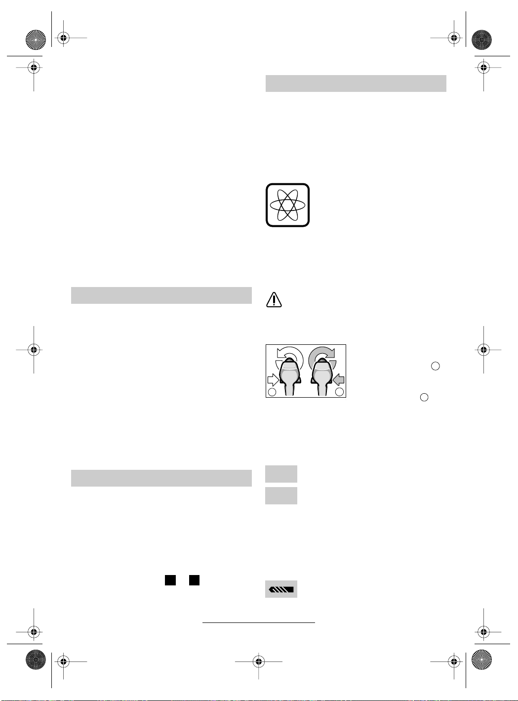
EURO • Printed in Malaysia • BA 2 609 140 186 • PSR 960-1440 • N • OSW 02.02
b
2 609 140 186.book Seite 2 Donnerstag, 7. Februar 2002 3:14 15
Batteri og lader
■ Les absolutt vedlagt bruksanvisning for la-
deren!
■ Batteri og lader er tilpasset hverandre. Til opplading må det kun brukes en Bosch-lader med
en ladespenning som passer til batteriet (se typeskilt). En kombinasjon av forskjellige spenninger medfører skader på batteri hhv. lader.
■ La oppvarmet batteri avkjøles før opplading.
■ Batteriet må beskyttes mot varme og ild: Fare
for eksplosjoner! Ikke legg batteriet på radiatorer eller utsett det for sterk sol i lengre tid. Temperaturer over 50 °C skader.
■ Batteriet må ikke åpnes og må beskyttes mot
støt. Må oppbevares tørt og frostfritt.
■ Kontaktene til batteriet som er trukket ut må
dekkes til. Ved kortslutning på grunn av metallisk brokopling er det fare for brann!
■ Ikke kast batteriet i vanlig søppel, i ild eller
vann.
Før start
Opplading av batteriet
Et nytt batteri eller et batteri som ikke har vært
brukt over lengre tid gir først sin fulle effekt etter
ca. 5 oppladings- og utladingssykluser.
Trykk låsetast 6 for å ta ut batteriet 5 og trekk batteriet ut oppover. Ikke bruk makt.
Batteriet er utstyrt med en NTC-temperaturovervåking som tillater lading kun i temperaturområdet mellom 0 °C og 45 °C. Herved oppnås det en
lang batteri-levetid.
En vesentlig kortere driftstid etter oppladingen er
et tegn på at batteriene er oppbrukt og må skiftes
ut.
■ Vennligst vær oppmerksom på avsnittet miljøvern.
Utskifting av verktøy
Chucken åpnes så mye at verktøyet kan settes
inn. Sett inn verktøyet.
Hold den bakre hylsen fast og skru den fremre
hylsen kraftig fast med hånden til det ikke lenger
høres en slurelyd («klikk»). Chucken låses da automatisk.
Låsen løser seg igjen når den fremre hylsen
dreies i motsatt retning til fjerning av verktøyet.
Skruing (se bildene + )
Spenn skrueklingen direkte in i chucken eller
bruk en ekstra universalbitsholder 8 ved bruk av
skrutrekkerinnsatser (bits) 7.
A B
Start
Innsetting av batteriet
Sett høyre-/venstregangsbryteren 3 i midten =
innkoblingssperre og la det oppladede batteriet 5
gå i lås i håndtaket.
Inn-/utkobling
Til igangsetting av maskinen trykkes på-/avbryteren 4.
Alt etter trykk på på- / av-bryteren 4
kjører maskinen med variabelt turtall mellom 0 og maksimum. Lett
trykk bevirker et lite turtall og muliggjør en myk, kontrollert start. Maskinen må ikke belastes så sterkt at
den stanser.
Til utkobling av maskinen slippes på-/av-bryteren 4.
Endring av dreieretningen
Dreieretningen må kun endres ved stillestående motor.
Med høyre-/venstrebryteren 3 endres maski-
nens dreieretning. Ved utløst på- /av-bryter 4 er
dette ikke mulig.
Til boring og inndreiing av
skruer må det innstilles
dreieretning HØYRE .
For å skru ut skruer set-
a
tes høyre-/venstre-bryte-
b
b
b
bbbb
ren på VENSTRE .
b
a
Turtalls-innstilling
I praktiske forsøk må du finne ut hvilke av de
5 mulighetene på dreiemoment-innstillingsringen 1 det er best å skru skruene inn i materialet
med.
Svak innstilling, f. eks. små skruer,
1
myke materialer.
Sterk innstilling f. eks. store skruer,
5
harde materialer.
Ved riktig innstilling utløses slurekoblingen
såsnart skruen er skrudd plant inn i materialet
hhv. det innstilte dreiemomentet er nådd. Velg en
høyere innstilling ved utskruing, hhv. innstill på
symbolet «Boring». Den riktige innstillingen må
finnes frem til med praktiske forsøk.
Boring
Sett dreiemoment-innstillingsringen 1
på symbolet «Boring».
39 • 2 609 140 186 • TMS • 01.02.02
Norsk - 2
Page 40

EURO • Printed in Malaysia • BA 2 609 140 186 • PSR 960-1440 • N • OSW 02.02
2 609 140 186.book Seite 3 Donnerstag, 7. Februar 2002 3:14 15
Arbeidshenvisninger
Nedkjøringsbremse
Mens en slipper på- /av-bryteren 4 bremses borpatronen og ved dette unngås det at verktøyet
først langsomt sakner hastigheten.
Ved arbeider med skrujern slippes på- /av-bryteren 4 først når skruen er skrudd inn plant med
materialet. Skruehodet trenger da ikke inn i materialet.
Skifte chuck
På maskiner uten borspindel-lås må chucken
skiftes ut av et autorisert serviceverksted for
Bosch-elektroverktøy.
Chucken må trekkes til med et dreiemoment på ca. 35–40 Nm.
Tips
■ For å dreie større, lengre skruer inn i harde
materialer er det best å forbore først.
Vedlikehold og rengjøring
■ Før alle arbeider på maskinen utføres må
batteriet tas ut.
Maskin og ventilasjonsspalter må alltid hol-
☞
des rene for å kunne arbeide bra og sikkert.
Skulle maskinen svikte til tross for omhyggelige
produksjons- og kontrollmetoder, må reparasjonen utføres av et autorisert serviceverksted for
Bosch-elektroverktøy.
Ved alle forespørsler og reservedelsbestillinger
må du absolutt oppgi maskinens 10-sifrede bestillingsnummer!
Miljøvern
Råstoffgjenvinning i stedet for avfallsdeponering.
Maskin, tilbehør og forpakning bør resirkuleres.
Denne bruksanvisningen er laget av klorfritt resir-
kulert papir.
For å kunne resirkulere på en skikkelig måte, er
kunststoffdelene markerte.
Nikkel-kadmium-batteri: Hvis produktet har et
nikkel-kadmium-batteri,
må batteriet innsamles,
resirkuleres eller deponeres på en miljøvennlig
måte.
Defekte eller oppbrukte batterier må resirkuleres
i henhold til direktivet 91/157/EØF.
Service og kundekonsulent
www.bosch-pt.com
Robert Bosch A/S
Trollaasveien 8
Postboks 10
N-1414 Trollaasen
✆ Kundekonsulent:........................ +47 66 81 70 00
.............................................................. +47 66 81 70 97
Fax
Samsvarserklæring
Vi overtar ansvaret for at dette produktet er i overenstemmelse med følgende standarder eller
standard-dokumenter: EN 50 144 (akku-redskap) hhv. EN 60 335 (akku-ladere) i samsvar
med bestemmelsene i direktivene 73/23/EØF,
89/336/EØF, 98/37/EF.
02
Dr. Gerhard Felten Dr. Eckerhard Strötgen
40 • 2 609 140 186 • TMS • 01.02.02
Robert Bosch GmbH, Geschäftsbereich Elektrowerkzeuge
Rett til endringer forbeholdes
Norsk - 3
Page 41

EURO • Printed in Malaysia • BA 2 609 140 186 • PSR 960-1440 • FIN • OSW 02.02
2 609 140 186.book Seite 1 Donnerstag, 7. Februar 2002 3:14 15
Tekniset tiedot
Akku-ruuvinväännin PSR 960 PSR 1200 PSR 1440
Tilausnumero 0 603 944 6.. 0 603 944 5.. 0 603 944 4..
Tyhjäkäyntikierrosluku [min-1] 0–550 0 – 700 0– 700
Vääntömomentti maks. [Nm] 12 15 15
Poran Ø: teräs [mm] 8 10 10
Poran-Ø pehmeään puuhun [mm] 14 20 25
Poran-Ø kovaan puuhun [mm] 8 10 10
Ruuvin Ø [mm] 6 8 8
Karan kierre 3/8" 3/8" 3/8"
Paino akkuineen [kg] 1,3 1,4 1,5
Akku NiCd NiCd NiCd
Lämpötilan valvonta NTC NTC NTC
Nimellisjännite [V=] 9,6 12 14,4
Paino [kg] 0,4 0,5 0,6
Ota huomioon koneesi tilausnumero. Yksittäisten koneiden kauppanimitys saattaa vaihdella.
Koneen osat
1 Vääntömomentin säätörengas
2 Pikaistukka
3 Suunnanvaihtokytkin
4 Käynnistyskytkin
5 Akku
6 Akun vapautuspainike
7 Ruuvitaltta
8 Teränpidin
Käyttöohjeissa kuvatut lisätarvikkeet eivät välttämättä
sisälly toimitukseen!
Asianmukainen käyttö
Laite on tarkoitettu ruuvinvääntöön ja poraamiseen puuhun, metalliin, keramiikkaan sekä muoviin.
Melu-/tärinätieto
Mitta-arvot määritetty EN 50 144 mukaan.
Yleensä työkalun A-luokan melutaso on alle
70 dB (A).
Työskenneltäessä melutaso saattaa ylittää
85 dB (A).
Käytä kuulosuojaimia!
Tyypillisesti käsivarren tärinä on alle 2,5 m/s
2
.
Työturvallisuus
Vaaraton työskentely laitteella
on mahdollinen ainoastaan
luettuasi huolellisesti käyttö- ja
turvaohjeet sekä seuraamalla
ohjeita tarkasti. Lisäksi tulee
noudattaa oheen liitetyn vihkosen yleisiä turvaohjeita.
■ Käytä suojalaseja.
■ Suojaa pitkät hiukset hiusverkolla. Työsken-
tele vain hyvin istuvissa vaatteissa.
■ Tarkista ennen jokaista käyttöä laite sekä
akku. Laitetta ei enää saa käyttää, jos vaurioita
on todettavissa. Ainoastaan ammattihenkilö
saa suorittaa korjauksen. Alä koskaan itse
avaa laitetta.
■ Akun nimellisjännitteen on täsmättävä laitteessa olevien tietojen kanssa.
■ Irrota akku ennen kaikkia laitteeseen kohdistuvia töitä ja konetta säilytettäessä.
■ Aseta aina suunnanvaihtokytkin keskiasentoon ennen akun asennusta ja työkalun vaihtoa sekä kuljetuksen ja säilytyksen ajaksi!
■ Varmista ennen käyttöä, että akku on tiukasti
paikallaan laitteessa.
■ Älä kuormita laitetta niin paljon, että se pysähtyy.
■ Pidä laitetta tukevasti: kiristettäessä saattaa
hetkellisesti syntyä voimakkaita vastamomentteja.
■ Älä koskaan anna lapsille lupaa käyttää laitetta.
■ Bosch takaa laitteen moitteettoman toiminnan
ainoastaan, jos käytetään tälle laitteelle tarkoitettuja alkuperäisiä varaosia.
41 • 2 609 140 186 • TMS • 01.02.02
Suomi - 1
Page 42

EURO • Printed in Malaysia • BA 2 609 140 186 • PSR 960-1440 • FIN • OSW 02.02
A
b
2 609 140 186.book Seite 2 Donnerstag, 7. Februar 2002 3:14 15
Akku ja latauslaite
■ Lue ehdottomasti latauslaitteen oheenlii-
tetty käyttöohje!
■ Akku ja latauslaite on sovitettu toisiinsa. Käytä
lataukseen ainoastaan siihen tarkoitettua
Bosch-latauslaitetta, jossa on akkua vastaava
latausjännite (katso tyyppikilvestä). Yhdistelmä, jossa akussa ja latauslaitteessa on toisistaan poikkeavat nimellisjännitteet johtaa
akun ja/tai latauslaitteen vaurioitumiseen.
■ Anna lämmenneen akun jäähtyä ennen latausta.
■ Suojaa akku kuumuudelta ja tulelta: Räjähdysvaara! Älä aseta akkua lämpöpatterin
päälle äläkä jätä pidemmäksi ajaksi suoraan
aurinkoon, yli 50 °C lämpötilat vahingoittavat
akkua.
■ Älä avaa akkua. Suojaa sitä iskuilta. Säilytä
akku kuivassa ja suojaa sitä pakkaselta.
■ Peitä irrallisen akun koskettimet. Metalliesineiden aiheuttaman oikosulun sattuessa on olemassa tulipalovaara.
■ Älä heitä akkua talousjätteisiin, tuleen tai veteen.
Ennen käyttöönottoa
Akun lataus
Uusi tai kauan käyttämättä ollut akku saavuttaa
täyden tehonsa vasta n. viiden lataus-purkausjakson jälkeen.
Irrota akku 5 painamalla vapautuspainiketta 6 ja
vetämällä akku ulos alaspäin. Älä käytä väkivaltaa.
Akku on varustettu lämpötilan valvontavastuksella (NTC), joka sallii latauksen vain lämpötilaalueella 0 °C – 45 °C. Tämä varotoimi pidentää
akun käyttöikää.
Huomattavasti lyhentynyt käyttöaika latauksen
jälkeen osoittaa, että akut ovat loppuun käytetyt
ja ne tulee uusia.
■ Ota huomioon myös ympäristönsuojelua koskevat suositukset.
Työkalunvaihto
Avaa poraistukka niin paljon, että työkalu voidaan
asentaa. Asenna työkalu.
Pidä kiinni taemmasta hylsystä ja kiristä voimakkaasti etummaista hylsyä käsin, kunnes ei enää
kuulu rasterinaksahdusta. Istukka lukkiutuu täten
automaattisesti.
Lukitus aukeaa, kun etummaista hylsyä kierretään vastakkaiseen suuntaan työkalun irrottamiseksi.
42 • 2 609 140 186 • TMS • 01.02.02
Suomi - 2
Ruuvaus (katso kuvat + )
Kiinnitä ruuvitaltta suoraan poraistukkaan tai
käytä lisäksi yleispidintä jos käytät ruuvauskärkiä
(Bits) 7.
B
Käyttöönotto
Akun kiinnitys
Aseta suunnanvaihtokytkin 3 keskiasentoon =
käynnistysvarmistin ja anna ladatun akun 5 luk-
kiutua kahvaan.
Käynnistys ja pysäytys
Käynnistä konetta painamalla käynnistys-
kytkintä 4.
Koneen kierrosluku vaihtelee nollasta maksimiin riippuen
käynnistyskytkimeen 4 kohdistuvasta paineesta. Kierrosluku on alhainen ja kone käynnistyy
pehmeästi, kun kytkintä painetaan
kevyesti. Älä kuormita konetta niin
paljon, että se pysähtyy.
Pysäytä kone irrottamalla ote
käynnistyskytkimestä 4.
Kiertosuunnan vaihto
Kiertosuuntaa saa vaihtaa vain koneen
ollessa kytkettynä pois päältä.
Suunnanvaihtokytkimellä 3 muutetaan koneen
kiertosuunta. Käynnistyskytkimen 4 ollessa pai-
nettuna ei suunnanvaihtoa kuitenkaan voida suorittaa.
Porausta ja ruuvien sisäänkiertämistä varten
on valittava kiertosuunta
RECHTS (oikealle) .
a
Ruuvien uloskiertämistä
b
b
b
bbbb
varten valitaan kiertosuunta LINKS
(vasemmalle) .
b
a
Vääntömomentin säätö
Käytännön kokein tulee määritellä millä vääntömomentin säätörenkaan 1 asetuksesta ruuvit
kiertyvät tasaan materiaaliin.
Alhainen vääntömomentti esim. pienille
1
ruuveille, pehmeälle materiaalille.
Suuri vääntömomentti esim. suurille
5
ruuveille, kovalle materiaalille.
Oikealla asetuksella avaa rasterikytkin heti, kun
ruuvi on kiertynyt tasaan materiaaliin tai, kun asetettu vääntömomentti on saavutettu. Valitse suu-
Page 43

EURO • Printed in Malaysia • BA 2 609 140 186 • PSR 960-1440 • FIN • OSW 02.02
2 609 140 186.book Seite 3 Donnerstag, 7. Februar 2002 3:14 15
rempi vääntömomentti ruuvien uloskiertämiseen
tai aseta säätö asentoon ”Poraus”. Oikea asetus
tulee määrittää käytännön kokeilla.
Poraus
Aseta vääntömomentin säätörengas 1
merkin ”Poraus” kohdalle.
Työskentelyohjeita
Pysäytysjarru
Kun käynnistyskytkin 4 lasketaan irti, pysäytys-
jarru jarruttaa poraistukkaa, mikä estää koneen
jälkikäynnin.
Kun ruuvaat, laske käynnistyskytkin 4 irti vasta
sitten, kun ruuvin kanta on samassa tasossa
työstettävän materiaalin kanssa. Silloin kanta ei
pääse pureutumaan materiaaliin.
Istukan vaihtaminen
Laitteissa, joissa ei ole poraistukan lukitusta, telee poraistukan vaihdon suorittaa valtuutettu
Bosch-sähkötyökalukorjaamo.
Istukka täytyy kiristää n. 35–40 Nm
vääntömomentilla.
Vihjeitä
■ Jos joudut kiinnittämään suurikokoisia, pitkiä
ruuveja kovaan materiaaliin, kannattaa ensin
esiporata alkureikä.
Huolto ja puhdistus
■ Poista akku ennen kaikkia laitteelle suoritettavia töitä.
Pidä aina laite ja tuuletusaukot puhtaina
☞
voidaksesi työskennellä hyvin ja turvallisesti.
Tämä laite on suunniteltu, valmistettu ja testattu
erittäin huolellisesti. Mikäli siinä siitä huolimatta ilmenee jokin vika, anna vain Bosch-huoltoliikkeen
suorittaa tarvittavat korjaukset.
Ilmoita ehdottomasti laitteen 10-numeroinen
tilausnumero kaikissa kyselyissä ja varaosatilauksissa!
Ympäristönsuojelu
Raaka-aineen uusiokäyttö jätehuollon asemasta
Laite, tarvikkeet ja pakkaus tulisi hävittää ympäristöystävällisesti toimittamalla ne kierrätykseen.
Nämä käyttöohjeet on valmistettu kloorittomasti
valkaistusta uusiopaperista.
Lajipuhdasta kierrättämistä varten muoviosissa
on merkinnät.
Nikkeli-kadmium-akku:
Jos laitteesi on varustettu
nikkeli-kadmium-akulla,
tulee akku ottaa talteen
kierrätystä varten tai hävitettävä ympäristöystävällisellä tavalla.
Vialliset ja loppuunkäytetyt akut täytyy kierrättää
direktiivin 91/157/ETY mukaisesti.
Huolto ja asiakasneuvonta
www.bosch-pt.com
Robert Bosch OY
Keskushuolto/Sähkötyökalut
Pakkalantie 21A
FIN-01510 Vantaa
✆ .............................................. +358 (0)9 / 27 05 34 61
✆ .............................................. +358 (0)9 / 27 05 34 62
✆ .............................................. +358 (0)9 / 27 05 34 63
................................................. +358 (0)9 / 8 70 23 18
Fax
Yhdenmukaisuusvakuutus
Todistamme täten ja vastaamme yksin siitä, että
tämä tuote on allalueteltujen standardien ja standardisoimisasiakirjojen vaatimusten mukainen:
EN 50 144 (akku-laitteet) ja EN 60 335 (akkulaturit) seuraavien direktiivien määräysten mukaisesti: 73/23/ETY, 89/336/ETY, 98/37/EY.
02
Dr. Gerhard Felten Dr. Eckerhard Strötgen
43 • 2 609 140 186 • TMS • 01.02.02
Robert Bosch GmbH, Geschäftsbereich Elektrowerkzeuge
Pidätämme oikeuden muutoksiin
Suomi - 3
Page 44

EURO • Printed in Malaysia • BA 2 609 140 186 • PSR 960-1440 • GR • OSW 02.02
2 609 140 186.book Seite 1 Donnerstag, 7. Februar 2002 3:14 15
Τεχνικά χαρακτηριστικά µηχανήµατοσ
∆ραπανοκατσάβιδο µπαταρίασ PSR 960 PSR 1200 PSR 1440
Κωδικσ αριθµσ 0 603 944 6.. 0 603 944 5.. 0 603 944 4..
Αριθ. στροφών χωρίσ φορτίο [min-1] 0 –550 0 –700 0 –700
Ροπή στρέψησ µέγ. [Nm] 12 15 15
Ø οπήσ σε χάλυβα [mm] 8 10 10
Ø τρύπασ σε µαλακ ξύλο [mm] 14 20 25
Ø τρύπασ σε σκληρ ξύλο [mm] 8 10 10
Ø βίδασ [mm] 6 8 8
Σπείρωµα άξονα 3/8" 3/8" 3/8"
Βάροσ µε µπαταρία [kg] 1,3 1,4 1,5
Μπαταρία NiCd NiCd NiCd
Επιτήρηση θερµοκρασίασ NTC NTC NTC
Ονοµαστική τάση [V=] 9,6 12 14,4
Βάροσ [kg] 0,4 0,5 0,6
Παρακαλούµε προσέξτε τον κωδικ αριθµ του µηχανήµατσ σασ. Ο εµπορικσ χαρακτηρισµσ ορισµένων
µηχανηµάτων µπορεί να διαφέρει.
Μέρη µηχανήµατοσ
1 ∆ακτύλιοσ ρύθµισησ ροπήσ στρέψησ
2 Τσοκ ταχείασ σύσφιξησ
3 ∆ιακπτησ αλλαγήσ φοράσ περιστροφήσ
4 ∆ιακπτησ ΟΝ/ΟFF
5 Μπαταρία
6 Πλήκτρο αποµανδάλωσησ µπαταρίασ
7 Κατσαβιδλαµα
8 Συγκρατήρασ για µύτεσ
Εξαρτήµατα που απεικονίζονται και περιγράφονται
στισ οδηγίεσ χρήσησ δεν συνοδεύουν πάντοτε το
µηχάνηµα!
Χρήση σύµφωνα µε τον προορισµ
Το µηχάνηµα προορίζεται για το βίδωµα και
λύσιµο βιδών, καθώσ και για τρύπηµα σε
ξύλα, σε µέταλλα, κεραµικά υλικά και
πλαστικά.
Πληροφορίεσ για θρυβο και
δονήσεισ
Εξακρίβωση των τιµών µέτρησησ σύµφωνα
µε EN 50 144.
Η σύµφωνα µε την καµπύλη Α εκτιµηθείσα
χαρακτηριστική στάθµη ακουστικήσ πίεσησ
τησ συσκευήσ είναι µικρτερη απ 70 dB (Α).
Η στάθµη θορύβου κατά την εργασία µπορεί
να ξεπεράσει τα 85 dB (Α).
Φοράτε ωτασπίδεσ!
Ο χαρακτηριστικσ κραδασµσ χεριούµπράτσου είναι χαµηλτεροσ απ 2,5 m/s
2
.
Για την ασφάλειά σασ
Ακίνδυνη εργασία µε το
µηχάνηµα είναι µνο δυνατή, αν
διαβάσετε πρώτα καλά λεσ τισ
οδηγίεσ χρήσησ και τισ
υποδείξεισ ασφάλειασ και
εφαρµζετε πάντοτε αυστηρά
τισ οδηγίεσ που περιέχονται σ΄
αυτέσ. Συµπληρωµατικά πρέπει
να τηρούνται και οι γενικέσ
υποδείξεισ ασφαλείασ που
περιέχονται στο
συµπαραδιδµενο φυλλάδιο.
■ Φοράτε προστατευτικά γυαλιά.
■ Οταν έχετε µακριά µαλλιά φοράτε
προστατευτικ µαλλιών. Εργάζεσθε πάντα
φορώντασ εφαρµοστά ρούχα.
■ Πριν απ κάθε χρήση ελέγχετε την
µπαταρία και το µηχάνηµα. Σε περίπτωση
εξακρίβωσησ βλαβών µη συνεχίζετε να
χρησιµοποιείτε το µηχάνηµα. Αφήστε έναν
ειδικ να διεξάγει την επισκευή. Μην
ανοίγετε ποτέ οι ίδιοι το µηχάνηµα.
■ Η ονοµαστική τάση τησ µπαταρίασ πρέπει
να αντιστοιχεί πλήρωσ στα στοιχεία επάνω
στο µηχάνηµα.
■ Πριν διεξάγετε οποιαδήποτε εργασία στο
ίδιο το µηχάνηµα καθώσ κι ταν πρκειται
να το διαφυλάξετε/να το αποθηκεύσετε
αφαιρέστε την µπαταρία.
44 • 2 609 140 186 • TMS • 01.02.02
Eλληνικά - 1
Page 45

EURO • Printed in Malaysia • BA 2 609 140 186 • PSR 960-1440 • GR • OSW 02.02
2 609 140 186.book Seite 2 Donnerstag, 7. Februar 2002 3:14 15
■ Πριν τοποθετήσετε την µπαταρία, κατά
την αλλαγή εργαλείου, καθώσ και κατά τη
µεταφορά ή τη διαφύλαξη, τοποθετήστε
το διακπτη αλλαγήσ φοράσ περιστροφήσ
στη µεσαία θέση!
■ Πριν απ κάθε χρήση βεβαιωθείτε τι η
µπαταρία µέσα στο µηχάνηµα «κάθεται»
εντάξει.
■ Μην επιβαρύνετε το µηχάνηµα τοσο πολύ,
ώστε να πάψει να λειτουργεί.
■ Συγκρατήτε γερά το µηχάνηµα: Κατά το
σφίξιµο µπορεί να εµφανιστούν πρσκαιρα
υψηλέσ αντιδραστικέσ ροπέσ
(κλοτσίµατα).
■ Μην επιτρέπετε ποτέ σε παιδιά τη χρήση
του µηχανήµατοσ.
■ Η Bosch εγγυάται την άψογη λειτουργία
του µηχανήµατοσ µνο ταν για το
µηχάνηµα αυτ χρησιµοποιούνται τα
προβλεπµενα γνήσια εξαρτήµατα.
Μπαταρία και φορτιστήσ
■ ∆ιαβάστε οπωσδήποτε τισ συνηµµένεσ
Οδηγίεσ χρήσησ του φορτιστή!
■ Η µπαταρία και ο φορτιστήσ είναι µεταξύ
τουσ εναρµονισµένοι. Για τη φρτιση
χρησιµοποιείτε πάντοτε τον
προβλεπµενο γι΄ αυτν το σκοπ
φορτιστή τησ Bosch µε την αντίστοιχη,
κατάλληλη για την µπαταρία, τάση
φρτισησ (βλέπε πινακίδα κατασκευαστή).
Ο συνδυασµσ µε διαφορετικέσ τάσεισ
οδηγεί σε βλάβη τησ µπαταρίασ ή/και του
φορτιστή.
■ Ζεσταµένεσ µπαταρίεσ πρέπει να
κρυώσουν πριν φορτιστούν.
■ Προστατεύετε την µπαταρία απ καύσωνα
και φωτιά: Κίνδυνοσ έκρηξησ! Μην
τοποθετείτε την µπαταρία πάνω σε
θερµαντικά σώµατα και µην την αφήνετε
για πολλή ώρα εκτεθειµένη σε δυνατή
ηλιοβολία. Θερµοκρασίεσ πάνω απ 50 °C
βλάπτουν.
■ Μην ανοίγετε την µπαταρία και
προφυλάγετέ την απ χτυπήµατα.
Αποθηκεύετέ την σε χώρο στεγν,
απρσιτο στην παγωνιά.
■ Καλύψτε τισ επαφέσ τησ αφαιρεθείσασ
µπαταρίασ. Σε περίπτωση
βραχυκυκλώµατοσ απ µεταλλική
επιγεφύρωση δηµιουργείται κίνδυνοσ
πυρκαϊάσ!
■ Μη ρίχνετε την µπαταρία στα απορρίµµατα
του νοικοκυριού σασ, στη φωτιά ή στο νερ.
Πριν θέσετε το µηχάνηµα σε
λειτουργία
Φρτιση τησ µπαταρίασ
Μια νέα µπαταρία ή µια µπαταρία που δε
χρησιµοποιήθηκε για αρκετ καιρ αποκτά
τη βέλτιστη απδοσή τησ µετά απ 5 περίπου
κύκλουσ φρτισησ-εκφρτισησ.
Για να αφαιρέσετε την µπαταρία 5 πατήστε
τα πλήκτρα αποµανδάλωσησ 6 και τραβήξτε
την µπαταρία προσ τα κάτω. Μη
χρησιµοποιήσετε βία.
Η µπαταρία φέρει µια επιτήρηση
θερµοκρασίασ NTC, που επιτρέπει τη
φρτιση µνο µεταξύ 0 και 45 βαθµών
Κελσίου. Έτσι κατορθώνεται να παρατείνεται
η ζωή του συσσωρευτή.
Μια σηµαντικά µειωµένη διάρκεια
λειτουργίασ µετά τη φρτιση σηµαίνει τι οι
µπαταρίεσ έχουν αναλωθεί και πρέπει να
αντικατασταθούν.
■ Τηρείτε τισ υποδείξεισ προστασίασ του
περιβάλλοντοσ.
Αλλαγή εργαλείου
Ανοίξτε το τσκ τσο, σο χρειάζεται για να
τοποθετήσετε το εργαλείο. Τοποθετήστε το
εργαλείο.
Συγκρατήστε το οπίσθιο κέλυφοσ και σφίξτε
το µπροστιν κέλυφοσ δυνατά µε το χέρι
ώσπου να µην ακούγεται πλέον ο θρυβοσ
καστάνιασ («κλικ»). Μ΄ αυτν τον τρπο
µανδαλώνει αυτµατα το τσοκ.
Η µανδάλωση λύνεται πάλι ταν, για την
αφαίρεση του εργαλείου, το κέλυφοσ
περιστραφεί προσ την αντίθετη κατεύθυνση.
Βίδωµα (βλέπ ικνσ + )
Συσφίξτε τη λάµα κατσαβιδιού κατ΄ ευθείαν
στο τσοκ ή, αν εργάζεσθε µε
κατσαβιδλαµεσ (Bits) 7, χρησιµοποιήστε
έναν φορέα γενικήσ χρήσησ 8.
A B
45 • 2 609 140 186 • TMS • 01.02.02
Eλληνικά - 2
Page 46

EURO • Printed in Malaysia • BA 2 609 140 186 • PSR 960-1440 • GR • OSW 02.02
b
2 609 140 186.book Seite 3 Donnerstag, 7. Februar 2002 3:14 15
Θέση σε λειτουργία
Τοποθέτηση µπαταρίασ
Τοποθετήστε το διακπτη αλλαγήσ φοράσ
περιστροφήσ 3 στη µέση = αποκλεισµσ
αθέλητησ ζεύξησ κι αφήστε τη φορτισµένη
µπαταρία 5 να «πιάσει» στη λαβή.
Θέση σε λειτουργία και εκτσ
λειτουργίασ
Για να θέσετε το µηχάνηµα σε λειτουργία
πατήστε το διακπτη ΟN/OFF 4.
Ανάλογα µε την πίεση που
εξασκείται στον διακπτη
ON/OFF 4, το µηχάνηµα
λειτουργεί µε µεταβλητ αριθµ
στροφών απ 0 µέχρι το
µέγιστο. Ελαφρή πίεση προκαλεί
µικρ αριθµ στροφών και
καθιστά έτσι δυνατή µια ήρεµη
και ελεγχµενη εκκίνηση. Μην
επιβαρύνετε το µηχάνηµα τσο
πολύ, ώστε να σταµατήσει να
κινείται.
Για να θέσετε το µηχάνηµα εκτσ
λειτουργίασ αφήστε το διακπτη ON/OFF 4
ελεύθερο.
Αλλαγή τησ φοράσ περιστροφήσ
Ο χειρισµσ του διακπτη αλλαγήσ
φοράσ περιστροφήσ 3 επιτρέπεται
µνο ταν το µηχάνηµα βρίσκεται
εκτσ λειτουργίασ.
Με το διακπτη αλλαγήσ φοράσ
περιστροφήσ 3 αλλάζεται η φορά
περιστροφήσ του µηχανήµατοσ. Αυτ, µωσ,
είναι αδύνατο, αν ο διακπτησ ON/OFF 4
είναι πατηµένοσ.
Για το τρύπηµα
και το βίδωµα πρέπει
να ρυθµίζεται
η φορά περιστροφήσ
a
∆ΕΞΙΑ .
b
b
b
bbbb
Για το ξεβίδωµα ο
διακπτησ αλλαγήσ
φοράσ περιστροφήσ
πρέπει να τοποθετηθεί
στη θέση ΑΡΙΣΤΕΡΑ .
b
a
Ρύθµιση στροφήσ στρέψησ
Εξακριβώστε µε πρακτική δοκιµή, σε ποια
απ τισ 5 θέσεισ του δακτύλιου ρύθµισησ
ροπήσ στρέψησ 1 οι βίδεσ βιδώνονται
«πρσωπο» στο υλικ.
Ασθενήσ ρύθµιση π. χ. µικρέσ βίδεσ,
1
µαλακά τεµάχια προσ κατεργασία.
Ισχυρή ρύθµιση π. χ. µεγάλεσ βίδεσ,
5
σκληρά τεµάχια προσ κατεργασία.
ταν η ρύθµιση είναι σωστή ο συµπλέκτησ
υπερπήδησησ ανοίγει µλισ η βίδα έχει µπει
«πρσωπο» στο υλικ ή αντίστοιχα µλισ
επιτευχτεί η ρυθµισµένη ροπή στρέψησ.
Κατά το ξεβίδωµα επιλέξτε µια υψηλτερη
ρύθµιση ή ρυθµίστε στο σύµβολο
«Τρύπηµα». Η σωστή ρύθµιση πρέπει να
εξακριβωθεί µε πρακτική δοκιµή.
∆ιάνοιξη οπών
Τοποθετήστε το δακτύλιο ρύθµισησ
ροπήσ στρέψησ 1 στο σύµβολο
«Τρύπηµα».
Υποδείξεισ για την εκτέλεση
εργασιών
΄Αµεση ανακοπή λειτουργίασ
Μλισ αφήσετε ελεύθερο τον διακπτη ON/
OFF 4, φρενάρει αµέσωσ το τσοκ και έτσι
ανακπτεται αµέσωσ η λειτουργία του
µηχανήµατοσ.
Κατά την εκτέλεση εργασιών βιδώµατοσ
αφήστε ελεύθερο τον διακπτη ON/OFF 4,
αφού προηγουµένωσ έχει βιδωθεί η βίδα
χωρίσ να προεξέχει απ το επίπεδο του
υλικού στο οποίο βιδώνεται. Η κεφαλή τησ
βίδασ δεν εισέρχεται έτσι µέσα στο υλικ.
Αντικατάσταση του τσοκ
Στα µηχανήµατα χωρίσ µανδάλωση άξονα το
τσοκ πρέπει να αντικατασταθεί απ µια
εξουσιοδοτηµένη γπηρεσία εξυπηρέτησησ
πελατών τησ Βosch.
Το τσοκ πρέπει να συσφίγγεται µε ροπή
έλξησ περίπου 35 – 40 Nm.
Συµβουλέσ
■ Καλ θα ήταν, να διεξάγετε µια
προδιάτρηση πριν βιδώσετε µεγάλεaσ,
µακριέσ βίδεσ.
46 • 2 609 140 186 • TMS • 01.02.02
Eλληνικά - 3
Page 47

EURO • Printed in Malaysia • BA 2 609 140 186 • PSR 960-1440 • GR • OSW 02.02
2 609 140 186.book Seite 4 Donnerstag, 7. Februar 2002 3:14 15
Συντήρηση και καθαρισµσ
■ Πριν απ κάθε εργασία στο ίδιο το
µηχάνηµα αφαιρέστε την µπαταρία.
∆ιατηρείτε το µηχάνηµα και τισ σχισµέσ
☞
αερισµού πάντα καθαρέσ.
Αν παρλεσ τισ επιµεληµένεσ µεθδουσ
κατασκευήσ και ελέγχου σταµατήσει κάποτε
το µηχάνηµα, ττε η επισκευή του πρέπει να
ανατεθεί σ΄ ένα εξουσιοδοτηµένο συνεργείο
ηλεκτρικών µηχανηµάτων τησ Bosch.
Οταν ζητάτε πληροφορίεσ και ταν
παραγγέλλετε ανταλλακτικά, παρακαλούµε
να αναφέρετε οπωσδήποτε το 10ψήφιο
κωδικ αριθµ που υπάρχει στην πινακίδα
κατασκευαστή!
Προστασία περιβάλλοντοσ
Ανακύκλωση πρώτων υλών αντί αποκοµιδή
απορριµάτων
Το µηχάνηµα, τα ειδικά εξαρτήµατα και η
συσκευασία θα πρέπει να αποσύρονται για
επανεπεξεργασία µε τρπο φιλικ προσ το
περιβάλλον.
Αυτέσ οι οδηγίεσ χρήσησ έχουν τυπωθεί σε
ανακυκλωµένο χαρτί λευκασµένο χωρίσ
χλώριο.
Για την ανακύκλωση κατά είδοσ τα πλαστικά
µέρη του µηχανήµατοσ φέρουν ένα σχετικ
χαρακτηρισµ.
Μπαταρία νικελίουκαδµίου: ταν το
προϊν σασ είναι
εξοπλισµένο µε µια
µπαταρία νικελίουκαδµίου, ττε η
µπαταρία πρέπει να
συλλεχτεί, να
ανακυκλωθεί ή να
αποσυρθεί µε τρπο
φιλικ προσ το
περιβάλλον.
Χαλασµένεσ ή αναλωµένεσ µπαταρίεσ πρέπει
να αποσύρονται σύµφωνα µε την Οδηγία
91/157/ΕΟΚ.
Υπηρεσία εξυπηρέτησησ πελατών
www.bosch-pt.com
Robert Bosch A.E.
Κηφισσού 162
12131 Περιστέρι-Αθήνα
✆ ................................................ +30 (0)1 / 57 70 081-3
..................................................... +30 (0)1 / 57 70 080
Fax
ABZ Service A.E.
✆ ............................................. +30 (0)1 / 57 70 081-83
✆ ............................................. +30 (0)1 / 57 01 375-78
..................................................... +30 (0)1 / 57 73 607
Fax
∆ήλωση συµβατικτητασ
∆ηλώνουµε υπευθύνωσ τι το προϊν αυτ
είναι κατασκευασµένο σύµφωνα µε τισ εξήσ
προδιαγραφέσ ή κατασκευαστικέσ συστάσεισ
ΕΝ 50 144 (συσκευέσ µπαταρίασ) ή
αντίστοιχα: ΕΝ 60 335 (φορτιστέσ
µπαταριών) σύµφωνα µε τισ διατάξεισ των
Οδηγιών 73/23ΕΟΚ, 89/336/ΕΟΚ, 98/37/ΕΚ.
02
Dr. Gerhard Felten Dr. Eckerhard Strötgen
Robert Bosch GmbH, Geschäftsbereich Elektrowerkzeuge
Τηρούµε το δικαίωµα αλλαγών
47 • 2 609 140 186 • TMS • 01.02.02
Eλληνικά - 4
Page 48
EURO • Printed in Malaysia • BA 2 609 140 186 • PSR 960-1440 • TR • OSW 02.02
2 609 140 186.book Seite 1 Donnerstag, 7. Februar 2002 3:14 15
Teknik veriler
Akülü vidalama makinesi PSR 960 PSR 1200 PSR 1440
Sipariµ no. 0 603 944 6.. 0 603 944 5.. 0 603 944 4..
Boµtaki devir say∂s∂ [/dak] 0 –550 0 –700 0 –700
Tork maks. [Nm] 12 15 15
Çelikte delme çap∂ [mm] 8 10 10
Delme çap∂; yumuµak ahµapta [mm] 14 20 25
Delme çap∂; sert ahµapta [mm] 8 10 10
Vidalama çap∂ [mm] 6 8 8
Matkap mili diµi 3/8" 3/8" 3/8"
Akü ile birlikte aπ∂rl∂π∂ [kg] 1,3 1,4 1,5
Akü NiCd NiCd NiCd
S∂cakl∂k kontrolü NTC NTC NTC
Anma gerilimi [V=] 9,6 12 14,4
Aπ∂rl∂π∂ [kg] 0,4 0,5 0,6
Lütfen aletinizin sipariµ numaras∂na dikkat edin. Aletlerin ticari kodlar∂ deπiµik olabilir.
Aletin elemanlar∂
1 Tork (dönme momenti) ayar halkas∂
2 Anahtars∂z uç takma mandreni
3 Saπ/sol dönüµ µalteri
4 Açma/kapama µalteri
5 Akü
6 Akü boµa alma düπmesi
7 Tornavida ucu (Bit)
8 Tornavida ucu yuvas∂
Kullan∂m k∂lavuzunda tan∂mlanan ve µekilleri gösterilen
akesuar∂n mutlaka teslimat kapsam∂nda bulunmas∂
gerekmez!
Usulüne uygun kullan∂m
Bu alet, Vidalar∂n tak∂l∂p, sökülmesi ile tahta,
metal, seramik ve plastik malzemedeki delme
iµleri için geliµtirilmiµtir.
Gürültü ve titreµim önleme hakk∂nda
bilgi
Ölçüm deπerleri EN 50 114’e göre
belirlenmektedir.
Frekansa baπ∂ml∂ uluslararas∂ ses bas∂nc∂
seviyesi deπerlendirme eπrisi A’ya göre bu aletin
tipik ses bas∂nc∂ seviyesi 70 dB’den düµüktür.
Ancak çal∂µma s∂ras∂nda gürültü seviyesi
85 dB (A)’y∂ aµabilir.
Koruyucu kulakl∂k kullan∂n!
Tipik el/kol titreµimi 2,5 m/s
2
’den düµük.
Güvenliπiniz ∑çin
Aletle güvenli bir biçimde
çal∂µabilmek için, kullan∂m
k∂lavuzu ve güvenlik talimatlar∂n∂
dikkatlice okuyup, belirtilen
hususlara titizlikle uymal∂s∂n∂z.
Ayr∂ca ekteki kitapç∂kta belirtilen
genel güvenlik talimat∂na da
uyulmal∂d∂r.
■ Koruyucu gözlük tak∂n.
■ Saçlar∂n∂z uzunsa saç koruyucu kullan∂n.
Sadece dar iµ giysileri ile çal∂µ∂n.
■ Çal∂µmaya baµlamadan önce her defas∂nda
aleti ve aküyü kontrol edin. Hasar tespit
ederseniz aleti kullanmay∂n. Onar∂mlar∂
sadece uzman∂na yapt∂r∂n. Aleti hiçbir zaman
kendiniz açmay∂n.
■ Akünün anma gerilimi aletin tip etiketi
üzerindeki verilere uygun olmal∂d∂r.
■ Aletin kendinde bir çal∂µma yapmadan önce
veya aleti saklarken aküyü ç∂kar∂n.
■ Uç deπiµtirmek üzere aküyü yerleµtirmeden
önce, aleti baµka bir yere naklederken veya
saklarken dönme yönü deπiµtirme µalterini orta
pozisyona getirin!
■ Çal∂µmaya baµlamadan önce akünün tam
olarak yerine oturup oturmad∂π∂n∂ kontrol edin.
■ Aleti duracak ölçüde zorlamay∂n.
■ Aleti s∂k∂ca tutun: Vida ve c∂vatalar∂n s∂k∂lmas∂
s∂ras∂nda k∂sa süreli reaksiyon momentleri
ortaya ç∂kabilir.
■ Çocuklar∂n aleti kullanmas∂na asla izin
vermeyin.
48 • 2 609 140 186 • TMS • 01.02.02
Türkçe - 1
Page 49

EURO • Printed in Malaysia • BA 2 609 140 186 • PSR 960-1440 • TR • OSW 02.02
b
b
2 609 140 186.book Seite 2 Donnerstag, 7. Februar 2002 3:14 15
■ Bosch ancak, bu alet için öngörülen orijinal
aksesuar kullan∂ld∂π∂ takdirde aletin kusursuz
iµlev göreceπini garanti eder.
Akü ve µarj cihaz∂
■ Aletle birlikte teslim edilen µarj cihaz∂
kullanma talimat∂n∂ mutlaka okuyun!
■ Akü ve µarj cihaz∂ birbirine uyumludur. Ωarj
iµlemi için sadece aküye uygun gerilimli Bosch
µarj cihaz∂ kullan∂n (aletin tip etiketine bak∂n).
Farkl∂ anma gerilimleri ile yap∂lacak
kombinasyon akü ve µarj cihaz∂nda hasara
neden olabilir.
■ Is∂nm∂µ aküyü µarj iµleminden önce soπumaya
b∂rak∂n.
■ Aküyü aµ∂r∂ s∂cakl∂ktan ve ateµten koruyun:
Patlama tehlikesi! Aküyü ∂s∂t∂c∂ veya kalorifer
petekleri üzerine b∂rakmay∂n veya uzun süre
güneµ ∂µ∂π∂ alt∂nda b∂rakmay∂n. 50 °C’nin
üzerindeki s∂cakl∂klar aküye zarar verir.
■ Aküyü açmay∂n ve darbelere karµ∂ koruyun.
Aküyü kuru ve donma tehlikesi olmayan bir
yerde saklay∂n.
■ D∂µar∂ ç∂kard∂π∂n∂z akünün kontak yerlerini
kapat∂n. Metal parçalara temas sonucu
oluµabilecek k∂sa devrelerde yang∂n tehlikesi
ortaya ç∂kabilir!
■ Aküyü evsel çöplerin, ateµin veya suyun içine
atmay∂n.
Aleti çal∂µt∂rmadan önce
Akünün µarj edilmesi
Yeni veya uzun süre kullan∂lmam∂µ bir akü ancak
yaklaµ∂k 5 kez µarj/deµarj olduktan sonra tam
performans∂na ulaµ∂r.
Aküyü 5 ç∂karmak için akü boµa alma
düπmesine 6 bas∂n ve aküyü aµaπ∂ doπru
çekerek ç∂kar∂n. Bu s∂rada zor kullanmay∂n.
Akü, µarj iµlemine ancak 0 ile 45 °C’ler aras∂nda
izin veren bir NTC s∂cakl∂k kontrol ünitesi ile
donat∂lm∂µt∂r. Bu sayede akülerin uzun ömürlü
olmas∂ saπlan∂r.
Eπer aküler µarj iµleminden sonra çok k∂sa bir
süre çal∂µ∂yor ve deµarj oluyorlarsa, kullan∂m
ömürlerini tamamlam∂µlar demektir ve
yenilenmelidirler.
■ Çevre koruma talimatlar∂na uyun.
Uç deπiµtirme
Mandreni, uç tak∂labilecek ölçüde aç∂n. Ucu
mandren içine yerleµtirin.
Arka kovan∂ s∂k∂ca tutun ve ön kovan∂ elinizle
“Klick” sesi duyulmay∂ncaya kadar s∂k∂n.
Mandren bu yolla otomatik olarak kilitlenir.
Ucu ç∂karmak için öndeki kovan ters yöne
çevrilince kilitleme aç∂l∂r.
Vidalama (Ωekillere bak∂n∂z + )
A B
Tornavida ucunu doπrudan mandren içinde s∂k∂n
veya küçük tornavida ucu (bit) 7 kullan∂yorsan∂z
ayr∂ca çok yönlü bir tornavida ucu 8 adaptörü
kullan∂n.
Çal∂µt∂rma
Akünün tak∂lmas∂
Dönme yönü deπiµtirme µalterini 3 orta konum =
kapama emniyetine getirin ve µarj edilmiµ aküyü
sap içine takarak kavrama yapt∂r∂n.
Açma/kapama
Aleti çal∂µt∂rmak için açma/kapama µalterine 4
bas∂n.
Alet, açma/kapama µalterine 4
yap∂lan bas∂nca göre, s∂f∂r ile
maksimum aras∂nda deπiµen devir
say∂s∂ ile çal∂µ∂r. Açma/kapama
µalterine hafifçe bas∂lmak suretiyle
düµük bir devir say∂s∂ elde edilir ve
bu sayede yumuµak, kontrollü bir
yol alma saπlan∂r. Aleti, durduracak
kadar zorlamay∂n.
Aleti kapatmak için açma/kapama µalterini 4
b∂rak∂n.
Dönme yönünün deπiµtirilmesi
Dönme yönünü sadece alet dururken
deπiµtirin.
Dönme yönü deπiµtirme µalteri 3 ile aletin dönme
yönü deπiµtirilir. Ancak açma/kapama µalteri 4
bas∂l∂ iken dönme yönü deπiµtirme µalteri iµlev
görmez.
Delme ve vidalama iµleri
için dönme yönünü
SA∏A ayarlay∂n.
Vidalar∂ sökerken dönme
a
yönü µalterini SOLA
b
b
b
bbbb
getirin.
a
Tork ayar∂
S∂kma torku en saπl∂kl∂ biçimde pratik deneyle
belirlenir. Tork ayar halkas∂ 1 ile 5 deπiµik tork
ayar∂ yap∂labilir ve bu sayede vidalar malzeme
içinde ayn∂ seviyede tak∂l∂r.
49 • 2 609 140 186 • TMS • 01.02.02
Türkçe - 2
Page 50

EURO • Printed in Malaysia • BA 2 609 140 186 • PSR 960-1440 • TR • OSW 02.02
2 609 140 186.book Seite 3 Donnerstag, 7. Februar 2002 3:14 15
Düµük güç ayar∂ örneπin küçük vidalar
1
ve yumuµak malzemeler için.
Yüksek güç ayar∂ örneπin büyük vidalar
5
ve sert malzemeler için.
Ayarlama doπru olarak yap∂l∂rsa, vida malzeme
içine tam istenen ölçüde girince veya ayarlanm∂µ
bulunan torka ulaµ∂ld∂π∂nda torklu kavrama
sistemi s∂kma iµlemini durdurur. Vidalar∂
sökerken daha yüksek bir tork ayarlay∂n veya
“Delme” sembolünü ayarlay∂n. Doπru ayarlama
en doπru olarak pratik deneyle belirlenebilir.
Delme
Tork ayar halkas∂n∂ 1 “Delme” sembolü
üzerine getirin.
Çal∂µ∂rken dikkat edilecek hususlar
Durdurma freni
Açma-kapama µalteri 4 serbest b∂rak∂l∂rsa
mandren frenlenir ve böylelikle de aletin serbest
dönüµü önlenir.
Vidalama yaparken, açma-kapama µalterini 4
vida bütünüyle malzeme içine girince b∂rak∂n. Bu
sayede vida baµ∂n∂n malzeme içine girmesini
önlersiniz.
Mandrenin deπiµtirilmesi
Matkap mili kilitleme fonksiyonu olmayan aletlerin
mandreni, Bosch elektrikli el aletleri için yetkili bir
müµteri servisi taraf∂ndan deπiµtirilmelidir.
Mandren yaklaµ∂k 35 – 40 Nm’lik bir
torkla s∂k∂lmal∂d∂r.
Aç∂klama ve öneriler
■ Sert malzemeye büyük ve uzun vidalar
yerleµtirirken, önceden delik açman∂zda yarar
vard∂r.
Bak∂m ve temizlik
■ Aletin kendinde bir çal∂µma yapmadan
önce aküyü ç∂kar∂n.
∑yi ve güvenli çal∂µabilmek için aleti ve
☞
havaland∂rma aral∂klar∂n∂ daima temiz
tutun.
Titiz üretim ve test yöntemlerine raπmen alet
ar∂za yapacak olursa, onar∂m, Bosch elektrikli el
aletleri için yetkili bir servise yapt∂r∂lmal∂d∂r.
Bütün baµvuru ve yedek parça sipariµlerinizde
lütfen aletin 10 haneli sipariµ numaras∂n∂ mutlaka
belirtin!
Çevre koruma
Çöp tasfiyesi yerine hammadde
kazan∂m∂
Alet, aksesuar ve ambalaj çevre
koruma hükümlerine uygun bir
yeniden deπerlendirme iµlemine
tabi tutulmal∂d∂r.
Bu kullan∂m talimat∂ da, klor kullan∂lmadan
aπart∂lm∂µ, yeniden dönüµümlü kâπ∂da
bas∂lm∂µt∂r.
Deπiµik malzemelerin tam olarak ayr∂l∂p, yeniden
deπerlendirme iµlemine sokulabilmesi için,
plastik parçalar iµaretlenmiµtir.
Nikel-Kadmiyum-Akü:
Eπer aletiniz bir nikel
kadmiyum akü ile
donat∂lm∂µsa, kullan∂m
ömrünü tamamlayan
aküyü rasgele atmay∂n,
recycling iµlemine (tekrar kazan∂m) iµlemine tabi
tutulmas∂n∂ saπlay∂n veya çevreye zarar
vermeyecek biçimde at∂n.
Bozuk veya kullan∂m ömrünü tamamlam∂µ aküler
91/157/AET hükümlerince Recyling iµlemine tabi
tutulmak zorundad∂rlar.
bir yerde toplay∂n,
Tamir Servisi
www.bosch-pt.com
Bosch San. ve Tic. A.S.
Ahi Evran Cad. No:1 Kat:22
Polaris Plaza
TR-80670 Maslak/Istanbul
✆ ............................................... +90 (0)212 / 335 06 00
.................................... +90 (0)212 / 346 00 48–49
Faks
Uygunluk beyan∂
Tek sorumlu olarak, bu ürünün aµaπ∂daki
standartlara veya standart belgelerine uygun
olduπunu beyan ederiz: 73/23/AET, 89/336/AET,
98/37/AT yönetmeliπi hükümleri uyar∂nca
EN 50 144 (akülü aletler) ve EN 60 335 (akü µarj
cihazlar∂).
02
Dr. Gerhard Felten Dr. Eckerhard Strötgen
Robert Bosch GmbH, Geschäftsbereich Elektrowerkzeuge
Deπiµiklikler mümkündür
50 • 2 609 140 186 • TMS • 01.02.02
Türkçe - 3
Page 51

EURO • Printed in Malaysia • BA 2 609 140 186 • PSR 960-1440 • Zubehör • OSW 02.02
2 609 140 186.book Seite 2 Donnerstag, 7. Februar 2002 3:14 15
2 608 572 080
2 607 000 205
2 607 000 221*
0,8 x 5,5 mm
2 607 000 239*
PH Nr. 2
2 607 335 ...
AL 300 SV
2 607 224 ...
2 605 439 014
2 607 000 248*
PZ Nr. 2
2 607 000 258*
T 20
2 607 000 317*
SW 3 mm
*
3×
2 605 439 013
2 605 439 012
2 605 439 015
2 609 160 062
51 • 2 609 140 186 • 02.02
Page 52

EURO • Printed in Malaysia • BA 2 609 140 186 • PSR 960 - 1440 • Titel (Rückseite) • OSW 02.02
2 609 140 186.book Seite 1 Donnerstag, 7. Februar 2002 3:14 15
Chlor
Robert Bosch GmbH
Geschäftsbereich Elektrowerkzeuge
D-70745 Leinfelden-Echterdingen
www.bosch-pt.com
2 609 140 186
Printed in Malaysia - Imprimé en Malaisie
(02.02) O / 56
 Loading...