

Page 1

sch
Praesideo 4.0
Цифровая система речевого и аварийного оповещения
ru Руководство по установке и эксплуатации
Page 2
Praesideo 4.0
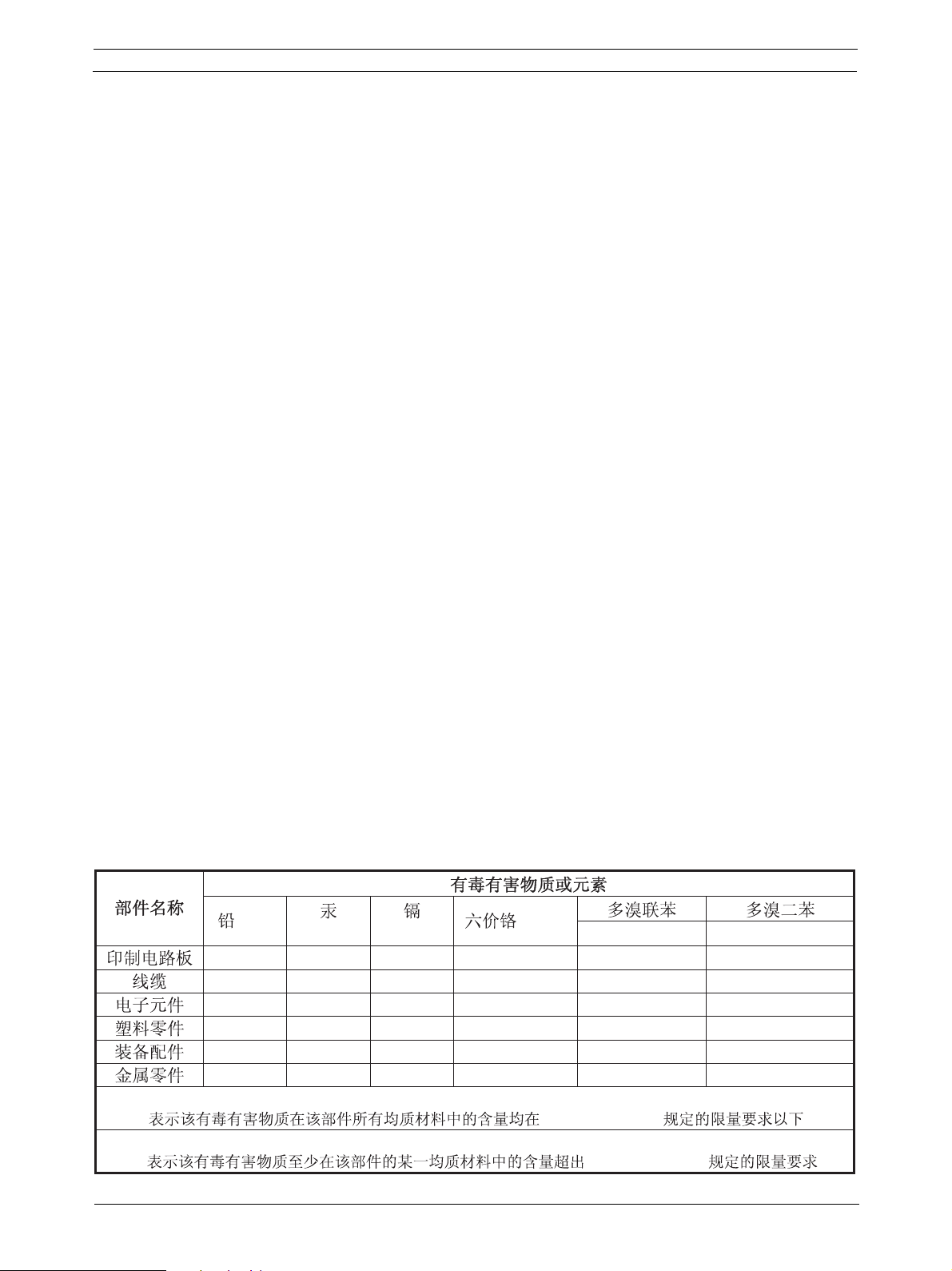
(Pb)
(Hg) (Cd)
(Cr6+)
(PBB's) (PBDE's)
X O O O O O
X O X X X X
X O X X O O
O O O O X X
X O X X O O
X O X X O O
O: SJ/T11363-2006 .
X: SJ/T11363-2006 .
ru | 2
Отказ от ответственности
Несмотря на усилия, приложенные для обеспечения
правильности информации и данных, приведенных в
настоящем руководстве по установке и эксплуатации,
его содержание не предоставляет никаких прав.
Компания Bosch Security Systems не предоставляет
никаких гарантий относительно информации,
представленной в настоящем руководстве.
Ни при каких обстоятельствах компания Bosch Security
Systems не несет ответственности за какой-либо
фактический, косвенный или сопутствующий ущерб,
вызванный утратой эксплуатационных качеств, данных
или прибыли, вследствие применения положений
контракта, халатности или неправомерных действий,
возникших на основании или в связи с использованием
информации, содержащейся в настоящем руководстве
по установке и эксплуатации.
Важные меры безопасности
Перед установкой или эксплуатацией данного изделия
ознакомьтесь с правилами техники безопасности,
которые представлены в виде отдельного документа и
поставляются со всеми устройствами, имеющими
возможность подключения к сети электропитания.
Требования Федерального
агентства по связи (США) к
ПРИМЕЧАНИЕ:
Данное оборудование было испытано и признано
соответствующим предельным значениям для цифровых
устройств класса A согласно Части 15 Правил Федерального
агентства по связи (США). Эти предельные значения
установлены для того, чтобы обеспечить надежную защиту от
критических помех при работе оборудования в коммерческом
окружении. Данное оборудование генерирует, принимает и
может излучать энергию на радиочастотах и
установлено и используется с нарушением настоящей
инструкции, может стать источником недопустимых помех для
радиосвязи.
районе может привести к созданию вредных помех, которые
пользователь должен будет устранять за свой счет.
Замечание Федерального агентства по связи
(США)
Данное устройство отвечает требованиям Части 15 Правил
Федерального агентства по связи (США). Работа
устройства должна отвечать двум следующим условиям.
1. Данное устройство не может являться источником
помех.
2. Данное устройство должно работать в условиях помех,
включая те, которые могут вызывать сбои в работе.
Внесение изменений
Любые не утвержденные производителем изменения
данного устройства могут привести к лишению
пользователя предоставленных Федеральным
агентством по связи (США) прав на эксплуатацию
данного оборудования.
Эксплуатация этого оборудования в жилом
, если устройство
устройствам класса A
Все устройства Praesideo признаны соответствующими
требованиям Подчасти 15 B Свода федеральных
нормативных актов (США) №47 «Излучатели
непреднамеренных помех». Цифровые устройства
класса A, периферийные устройства и внешние
импульсные источники электропитания.
Канада
Данное цифровое устройство класса A отвечает
требованиям стандарта Канады ICES-003.
Cet appareil numérique de la classe A est conforme à la
norme NMB-003 du Canada.
Bosch Security Systems B.V.
Инструкции по установке и эксплуатации.
IUI-PRAESIDEO_4.0 | V1.0 | 2013.01
Page 3

Praesideo 4.0
ru | 3
Содержание
Отказ от ответственности................................................................................................................................. 2
Важные меры безопасности ............................................................................................................................ 2
Требования Федерального агентства по связи (США) к устройствам класса A .................................... 2
Содержание ......................................................................................................................................................... 3
Системы аварийного речевого оповещения .............................................................................................. 23
EN60849: 1998 контрольный перечень соответствия ............................................................................... 25
EN54-16: 2008 compliancy checklist................................................................................................................ 41
EN54-16: 2008 VACIE label................................................................................................................................ 74
EN54-16: 2008 products description ................................................................................................................ 76
ISO7240-16: 2007 compliancy checklist .......................................................................................................... 79
Praesideo на борту корабля............................................................................................................................ 89
1 Информация о руководстве ..................................................................................................................... 93
1.1 Цель этого руководства ....................................................................................................................... 93
1.2 Предполагаемая аудитория ................................................................................................................ 93
1.3 Доступная документация ..................................................................................................................... 93
1.4 Предупреждения ................................................................................................................................... 93
1.5 Значки .................................................................................................................................................... 93
2 Обзор системы ........................................................................................................................................... 94
2.1 Введение ............................................................................................................................................... 94
2.2 Удобное в работе программное управление ..................................................................................... 94
2.3 Сетевой подход .................................................................................................................................... 94
2.4 Распределенное управление .............................................................................................................. 94
2.5 Комбинация функций ........................................................................................................................... 94
2.6 Соответствие стандартам эвакуации ................................................................................................. 95
2.7 Внешние интерфейсы .......................................................................................................................... 95
2.8 Снижение затрат на монтаж ................................................................................................................ 95
2.9 Высокая гибкость системы ................................................................................................................... 95
3 Вызовы ........................................................................................................................................................ 96
3.1 Введение ............................................................................................................................................... 96
3.2 Компоненты
3.2.1 Введение .......................................................................................................................................... 96
3.2.2 Приоритет ......................................................................................................................................... 96
3.2.3 Содержимое вызова ........................................................................................................................ 96
3.2.4 Направление трансляции ................................................................................................................ 96
3.2.5 Синхронизация ................................................................................................................................. 97
3.2.6 Размер системы ...............................................................................................................................97
3.3 Типы вызовов ........................................................................................................................................ 97
3.3.1 Введение .......................................................................................................................................... 97
3.3.2 Вызовы BGM .................................................................................................................................... 97
3.3.3 Нормальные вызовы ........................................................................................................................ 97
3.3.4 Экстренные вызовы ......................................................................................................................... 97
4 Словарь специальных терминов ............................................................................................................ 98
5 Сетевой контроллер PRS-NCO3 .............................................................................................................. 99
5.1 Введение ............................................................................................................................................... 99
5.2 Органы управления, разъемы и индикаторы ................................................................................... 100
5.2.1 Вид спереди ................................................................................................................................... 100
вызовов ............................................................................................................................ 96
Bosch Security Systems B.V.
Инструкции по установке и эксплуатации.
IUI-PRAESIDEO_4.0 | V1.0 | 2013.01
Page 4

Praesideo 4.0
5.2.2 Вид сзади ........................................................................................................................................ 100
5.2.3 Вид изнутри ................................................................................................................................... 102
5.3 Соединения ......................................................................................................................................... 103
5.3.1 Введение ........................................................................................................................................ 103
5.3.2 Подсоединение питающей сети ................................................................................................... 103
5.3.3 Подсоединение резервного электропитания ............................................................................... 103
5.3.4 Подсоединение сети ...................................................................................................................... 104
5.3.5 Присоединение ПК ......................................................................................................................... 104
5.3.6 Подсоединение аудиовходов ........................................................................................................ 104
5.3.7 Подсоединение аудиовыходов ..................................................................................................... 105
5.3.8 Подсоединение управляющих входов ......................................................................................... 105
5.3.9 Подсоединение выходов управляющего сигнала. ...................................................................... 106
5.3.10 Настройка выключателей устройства звуковой сигнализации .................................................. 106
5.3.11 Использование дополнительного выхода 24 В ........................................................................... 107
5.3.12 Подсоединение порта RS232 ........................................................................................................ 107
5.3.13 Карта памяти Compact Flash Card ................................................................................................ 108
5.4 Установка ............................................................................................................................................ 108
5.5 Использование конфигурационного меню ....................................................................................... 109
5.5.1 Обзор .............................................................................................................................................. 109
5.5.2 Навигация по меню ........................................................................................................................ 110
5.6 Конфигурация и работа устройства .................................................................................................. 113
5.6.1 Введение ........................................................................................................................................ 113
5.6.2 Запуск ............................................................................................................................................. 113
5.6.3 Экраны состояния .......................................................................................................................... 113
5.6.4 Меню Emergency ............................................................................................................................ 113
5.6.5 Меню неисправностей (Faults) ...................................................................................................... 113
5.6.6 Основное меню .............................................................................................................................. 114
5.6.7 Установка опций мониторинга ...................................................................................................... 117
5.6.8 Установка даты и времени ............................................................................................................ 117
5.6.9 Установка TCP/IP ........................................................................................................................... 117
5.6.10 Просмотр адреса MAC .................................................................................................................. 118
5.6.11 Информация о версии ................................................................................................................... 118
5.7 Технические данные ........................................................................................................................... 119
5.7.1 Физические характеристики .......................................................................................................... 119
5.7.2 Условия эксплуатации .................................................................................................................. 119
5.7.3 ЭМС и безопасность ...................................................................................................................... 119
5.7.4 Средняя наработка на отказ ........................................................................................................ 119
5.7.5 Системная шина ............................................................................................................................ 119
5.7.6 Источник питания ........................................................................................................................... 119
5.7.7 Батарея электропитания ............................................................................................................... 119
5.7.8 Линейные аудиовходы ................................................................................................................... 120
5.7.9 Микрофонные аудиовходы (только вход 1 и вход 2) .................................................................. 120
5.7.10 Аудиовыходы ................................................................................................................................. 121
5.7.11 Входы управляющего сигнала ...................................................................................................... 121
5.7.12 Управляющие выходы ................................................................................................................... 122
5.7.13 Интерфейс RS232 .......................................................................................................................... 122
5.7.14 Ethernet ........................................................................................................................................... 122
5.7.15 Головные телефоны ...................................................................................................................... 122
ru | 4
Bosch Security Systems B.V.
Инструкции по установке и эксплуатации.
IUI-PRAESIDEO_4.0 | V1.0 | 2013.01
Page 5

Praesideo 4.0
ru | 5
6 LBB4402/00 Аудиорасширитель ............................................................................................................ 123
6.1 Введение ............................................................................................................................................. 123
6.2 Органы управления и разъемы ......................................................................................................... 123
6.2.1 Вид спереди ................................................................................................................................... 123
6.2.2 Вид сзади ........................................................................................................................................ 124
6.3 Соединения ......................................................................................................................................... 125
6.3.1 Введение ........................................................................................................................................ 125
6.3.2 Присоединение сети ...................................................................................................................... 125
6.3.3 Подсоединение аудиовходов ........................................................................................................ 125
6.3.4 Подсоединение аудиовыходов ..................................................................................................... 125
6.3.5 Подсоединение управляющих входов ......................................................................................... 126
6.3.6 Подсоединение выходов управляющего сигнала. ...................................................................... 127
6.4 Установка ............................................................................................................................................ 127
6.5 Использование конфигурационного меню ....................................................................................... 128
6.5.1 Обзор .............................................................................................................................................. 128
6.5.2 Навигация по меню ........................................................................................................................ 129
6.6 Конфигурация и работа устройства .................................................................................................. 131
6.6.1 Введение ..............................................................................................................................
.......... 131
6.6.2 Запуск ............................................................................................................................................. 131
6.6.3 Экраны состояния .......................................................................................................................... 131
6.6.4 Статус неисправности ................................................................................................................... 131
6.6.5 Основное меню .............................................................................................................................. 131
6.6.6 Установка опций мониторинга ...................................................................................................... 132
6.6.7 Информация о версии ................................................................................................................... 132
6.7 Технические данные ........................................................................................................................... 133
6.7.1 Физические характеристики .......................................................................................................... 133
6.7.2 Условия эксплуатации ................................................................................................................... 133
6.7.3 ЭМС и безопасность ...................................................................................................................... 133
6.7.4 Средняя наработка на отказ ........................................................................................................ 133
6.7.5 Системная шина ............................................................................................................................ 133
6.7.6 Линейные аудиовходы ................................................................................................................... 133
6.7.7 Микрофонные аудиовходы (только вход 1 и вход 2) .................................................................. 134
6.7.8 Аудиовыходы ................................................................................................................................. 134
6.7.9 Входы управляющего сигнала ...................................................................................................... 135
6.7.10 Управляющие выходы ................................................................................................................... 135
6.7.11 Головные телефоны ...................................................................................................................... 135
7 Интерфейс LBB4404/00 CobraNet .......................................................................................................... 136
7.1 Введение ............................................................................................................................................. 136
7.2 Органы управления и разъемы ......................................................................................................... 137
7.2.1 Вид спереди ................................................................................................................................... 137
7.3 Вид сзади ............................................................................................................................................ 137
7.4 Соединения ......................................................................................................................................... 137
7.4.1 Введение ........................................................................................................................................ 137
7.4.2 Подсоединение сети Praesideo ..................................................................................................... 137
7.4.3 Подсоединение сети CobraNet .................................................................................................... 137
7.4.4 Подсоединение управляющих входов ......................................................................................... 139
7.4.5 Подсоединение выходов управляющего сигнала. ...................................................................... 139
7.5 Установка ............................................................................................................................................ 140
Bosch Security Systems B.V.
Инструкции по установке и эксплуатации.
IUI-PRAESIDEO_4.0 | V1.0 | 2013.01
Page 6

Praesideo 4.0
ru | 6
7.6 Конфигурация CobraNet ..................................................................................................................... 140
7.7 Использование конфигурационного меню ....................................................................................... 141
7.7.1 Обзор .............................................................................................................................................. 141
7.7.2 Навигация по меню ........................................................................................................................ 142
7.8 Конфигурация и работа устройства .................................................................................................. 144
7.8.1 Введение ........................................................................................................................................ 144
7.8.2 Запуск ............................................................................................................................................. 144
7.8.3 Экраны состояния .......................................................................................................................... 144
7.8.4 Статус неисправности ................................................................................................................... 144
7.8.5 Основное меню .............................................................................................................................. 144
7.8.6 Установка опций мониторинга ...................................................................................................... 145
7.8.7 Информация о версии ................................................................................................................... 145
7.9 Технические данные ........................................................................................................................... 146
7.9.1 Физические характеристики .......................................................................................................... 146
7.9.2 Условия эксплуатации ................................................................................................................... 146
7.9.3 ЭМС и безопасность ...................................................................................................................... 146
7.9.4 Средняя наработка на отказ ........................................................................................................ 146
7.9.5
Системная шина ............................................................................................................................ 146
7.9.6 Входы управляющего сигнала ...................................................................................................... 146
8 Усилители мощности ............................................................................................................................... 147
8.1 Введение ............................................................................................................................................. 147
8.2 Элементы управления, разъемы и индикаторы .............................................................................. 148
8.2.1 Вид спереди ................................................................................................................................... 148
8.2.2 Вид сзади ........................................................................................................................................ 148
8.3 Соединения ......................................................................................................................................... 150
8.3.1 Введение ........................................................................................................................................ 150
8.3.2 Подключение питающей сети ....................................................................................................... 150
8.3.3 Подключение сети ......................................................................................................................... 150
8.3.4 Заземление .................................................................................................................................... 150
8.3.5 Подключение каналов усилителя ................................................................................................. 151
8.3.6 Подключение аудиовходов ........................................................................................................... 155
8.3.7 Подключение управляющих входов ............................................................................................. 156
8.3.8 Подключение резервного электропитания .................................................................................. 157
8.4 Управление вентиляторами .............................................................................................................. 158
8.5
Установка ............................................................................................................................................ 159
8.6 Использование конфигурационного меню ....................................................................................... 160
8.6.1 Обзор .............................................................................................................................................. 160
8.6.2 Навигация по меню ........................................................................................................................ 161
8.7 Конфигурация и работа с устройством ............................................................................................. 163
8.7.1 Введение ........................................................................................................................................ 163
8.7.2 Запуск ............................................................................................................................................. 163
8.7.3 Экран состояния ............................................................................................................................ 163
8.7.4 Основное меню .............................................................................................................................. 164
8.7.5 Установка опций мониторинга ...................................................................................................... 164
8.7.6 Информация о версии ................................................................................................................... 164
8.8 Технические данные ........................................................................................................................... 165
8.8.1 Физические характеристики .......................................................................................................... 165
8.8.2 Условия эксплуатации ................................................................................................................... 165
Bosch Security Systems B.V.
Инструкции по установке и эксплуатации.
IUI-PRAESIDEO_4.0 | V1.0 | 2013.01
Page 7

Praesideo 4.0
ru | 7
8.8.3 ЭМС и безопасность ...................................................................................................................... 165
8.8.4 Средняя наработка на отказ ......................................................................................................... 165
8.8.5 Системная шина ............................................................................................................................ 165
8.8.6 Электропитание ............................................................................................................................. 165
8.8.7 Резервное питание ........................................................................................................................ 165
8.8.8 Потребляемая мощность .............................................................................................................. 166
8.8.9 Линейные аудиовходы ................................................................................................................... 167
8.8.10 Микрофонные входы ..................................................................................................................... 167
8.8.11 Выходы и резервные входы громкоговорителя .......................................................................... 168
8.8.12 Допустимые отклонения от номинальных значений параметров .............................................. 169
8.8.13 Входы управляющего сигнала ...................................................................................................... 169
8.8.14 Управляющие выходы ................................................................................................................... 170
8.8.15 Головные телефоны ...................................................................................................................... 170
9 PRS-16MCI Многоканальный интерфейс ............................................................................................. 171
9.1 Введение ............................................................................................................................................. 171
9.2 Элементы управления,
соединения и индикаторы .......................................................................... 172
9.2.1 Вид спереди ................................................................................................................................... 172
9.2.2 Вид сзади ........................................................................................................................................ 172
9.3 Разъемы .............................................................................................................................................. 173
9.3.1 Введение ........................................................................................................................................ 173
9.3.2 Подключение к базовому усилителю ........................................................................................... 173
9.3.3 Подключение сети ......................................................................................................................... 174
9.3.4 Подключение обхода многоканального интерфейса .................................................................. 174
9.3.5 Подключение управляющих входов ............................................................................................. 174
9.3.6 Подключение выходов управляющего сигнала. .......................................................................... 176
9.3.7 Заземление .................................................................................................................................... 176
9.4 Установка ............................................................................................................................................ 176
9.5 Конфигурация и работа с устройством ............................................................................................. 176
9.5.1 Обзор .............................................................................................................................................. 176
9.5.2 Отказоустойчивость ....................................................................................................................... 176
9.5.3 Взаимодействие многоканального интерфейса и базового
усилителя .................................... 177
9.5.4 Светодиодная индикация передней панели ................................................................................ 177
9.6 Технические данные ........................................................................................................................... 178
9.6.1 Физические характеристики .......................................................................................................... 178
9.6.2 Условия эксплуатации .................................................................................................................. 178
9.6.3 ЭМС и безопасность ...................................................................................................................... 178
9.6.4 Средняя наработка на отказ ........................................................................................................ 178
9.6.5 Электропитание ............................................................................................................................. 178
9.6.6 Потребляемая мощность .............................................................................................................. 178
9.6.7 Входы управляющего сигнала ...................................................................................................... 178
9.6.8 Управляющие выходы ................................................................................................................... 179
9.6.9 Обход аудиозвука .......................................................................................................................... 179
9.6.10 Соединения базового усилителя .................................................................................................. 179
10 Базовые усилители ................................................................................................................................. 180
10.1 Введение ............................................................................................................................................. 180
10.2 Элементы управления, соединения и индикаторы .......................................................................... 181
10.2.1 Передняя панель
........................................................................................................................... 181
10.2.2 Задняя панель ................................................................................................................................ 181
Bosch Security Systems B.V.
Инструкции по установке и эксплуатации.
IUI-PRAESIDEO_4.0 | V1.0 | 2013.01
Page 8

Praesideo 4.0
ru | 8
10.3 Разъемы .............................................................................................................................................. 183
10.3.1 Введение ........................................................................................................................................ 183
10.3.2 Подключение к сети электропитания ........................................................................................... 183
10.3.3 Соединение с многоканальным интерфейсом ............................................................................ 183
10.3.4 Заземление .................................................................................................................................... 184
10.3.5 Подключение каналов усилителя ................................................................................................. 184
10.3.6 Подключение локального аудиовхода ......................................................................................... 188
10.3.7 Подключение резервного электропитания .................................................................................. 188
10.4 Управление вентиляторами .............................................................................................................. 189
10.5 Установка ............................................................................................................................................ 191
10.6 Работа ................................................................................................................................................. 191
10.7 Технические данные ........................................................................................................................... 192
10.7.1 Физические характеристики .......................................................................................................... 192
10.7.2 Условия эксплуатации ................................................................................................................... 192
10.7.3 ЭМС и безопасность ...................................................................................................................... 192
10.7.4 Средняя наработка на отказ ........................................................................................................ 192
10.7.5 Соединение MCI ............................................................................................................................ 192
10.7.6 Электропитание
............................................................................................................................. 192
10.7.7 Резервное питание ........................................................................................................................ 192
10.7.8 Потребляемая мощность .............................................................................................................. 193
10.7.9 Линейные аудиовходы ................................................................................................................... 194
10.7.10Выходы и резервные входы громкоговорителя .......................................................................... 194
10.7.11Допустимые отклонения от номинальных значений параметров .............................................. 195
11 Контроль одной линии громкоговорителя ......................................................................................... 196
11.1 Введение ............................................................................................................................................. 196
11.2 Элементы управления, разъемы и индикаторы .............................................................................. 197
11.2.1 Плата Supervision-master .............................................................................................................. 197
11.2.2 Плата Supervision-slave ................................................................................................................. 197
11.3 Установка ............................................................................................................................................ 198
11.3.1 Плата Supervision-master ...........................................................................................................
... 198
11.3.2 Плата Supervision-slave ................................................................................................................. 200
11.4 Технические данные Supervision-master ........................................................................................... 201
11.4.1 Физические характеристики .......................................................................................................... 201
11.4.2 Условия эксплуатации ................................................................................................................... 201
11.4.3 ЭМС и безопасность ...................................................................................................................... 201
11.4.4 Средняя наработка на отказ ......................................................................................................... 201
11.5 Технические данные Supervision-slave ............................................................................................. 202
11.5.1 Физические характеристики .......................................................................................................... 202
11.5.2 Условия эксплуатации ................................................................................................................... 202
11.5.3 ЭМС и безопасность ...................................................................................................................... 202
11.5.4 Средняя наработка на отказ ......................................................................................................... 202
11.5.5 Характеристики линии громкоговорителей .................................................................................. 202
12 Контроль нескольких
линий громкоговорителей .............................................................................. 203
12.1 Введение ............................................................................................................................................. 203
12.2 Элементы управления, разъемы и индикаторы .............................................................................. 204
12.2.1 Плата управления контролем ....................................................................................................... 204
12.2.2 Плата контроля громкоговорителя ............................................................................................... 204
12.2.3 Плата контроля линии EOL ........................................................................................................... 205
Bosch Security Systems B.V.
Инструкции по установке и эксплуатации.
IUI-PRAESIDEO_4.0 | V1.0 | 2013.01
Page 9

Praesideo 4.0
ru | 9
12.3 Установка ............................................................................................................................................ 205
12.3.1 Плата управления контролем ....................................................................................................... 205
12.3.2 Плата контроля громкоговорителя ............................................................................................... 206
12.3.3 Плата контроля линии EOL ........................................................................................................... 208
12.4 Адресация ........................................................................................................................................... 208
12.5 Технические данные платы управления контролем ........................................................................ 209
12.5.1 Физические характеристики .......................................................................................................... 209
12.5.2 Условия эксплуатации ................................................................................................................... 209
12.5.3 ЭМС и безопасность ...................................................................................................................... 209
12.5.4 Средняя наработка на отказ ......................................................................................................... 209
12.6 Технические данные платы контроля громкоговорителя ................................................................ 210
12.6.1 Физические характеристики .......................................................................................................... 210
12.6.2 Условия эксплуатации ................................................................................................................... 210
12.6.3 ЭМС и безопасность ...................................................................................................................... 210
12.6.4 Средняя наработка на
отказ ......................................................................................................... 210
12.6.5 Характеристики линии громкоговорителей .................................................................................. 210
12.7 Технические данные платы контроля линии .................................................................................... 211
13 Кронштейны LBB4446/00 ......................................................................................................................... 212
14 Соединительный адаптер LBC1256/00 EVAC ...................................................................................... 213
14.1 Введение ............................................................................................................................................. 213
14.2 Установка ............................................................................................................................................ 213
14.3 Технические данные ........................................................................................................................... 214
15 LBB4430/00 Базовая вызывная станция .............................................................................................. 217
15.1 Введение ............................................................................................................................................. 217
15.2 Элементы управления, разъемы и индикаторы .............................................................................. 218
15.3 Подключения ....................................................................................................................................... 218
15.3.1 Введение ........................................................................................................................................ 218
15.3.2 Подключение сети ......................................................................................................................... 218
15.3.3 Подключение гарнитуры ................................................................................................................ 218
15.4 Установка ............................................................................................................................................ 220
15.5 Работа ................................................................................................................................................. 220
15.6 Технические
данные ........................................................................................................................... 221
15.6.1 Габаритные размеры: .................................................................................................................... 221
15.6.2 Условия эксплуатации ................................................................................................................... 221
15.6.3 ЭМС и безопасность ...................................................................................................................... 221
15.6.4 Средняя наработка на отказ ........................................................................................................ 221
15.6.5 Системная шина ............................................................................................................................ 221
15.6.6 Микрофон ....................................................................................................................................... 221
15.6.7 Loudspeaker (Громкоговоритель) .................................................................................................. 221
15.6.8 Гарнитура ....................................................................................................................................... 221
16 LBB4432/00 Клавиатура для вызывной станции ................................................................................ 222
16.1 Введение ............................................................................................................................................. 222
16.2 Элементы управления, разъемы и индикаторы .............................................................................. 222
16.2.1 Вид сверху ...................................................................................................................................... 222
16.2.2 Вид снизу ........................................................................................................................................ 223
16.3 Конфигурация ..................................................................................................................................... 223
16.4 Установка ............................................................................................................................................ 224
16.5 Работа ................................................................................................................................................. 225
Bosch Security Systems B.V.
Инструкции по установке и эксплуатации.
IUI-PRAESIDEO_4.0 | V1.0 | 2013.01
Page 10

Praesideo 4.0
ru | 10
16.6 Технические данные ........................................................................................................................... 225
16.6.1 Физические размеры ..................................................................................................................... 225
16.6.2 Условия эксплуатации ................................................................................................................... 225
16.6.3 ЭМС и безопасность ...................................................................................................................... 225
16.6.4 Средняя наработка на отказ ........................................................................................................ 225
16.6.5 Системная шина ............................................................................................................................ 225
17 Цифровая клавиатура PRS-CSNKP ....................................................................................................... 226
17.1 Введение ............................................................................................................................................. 226
17.2 Совместимость ................................................................................................................................... 226
17.3 Элементы управления, разъемы и индикаторы .............................................................................. 226
17.3.1 Вид сверху ...................................................................................................................................... 226
17.4 Вид снизу ............................................................................................................................................. 226
17.5 Установка ............................................................................................................................................ 227
17.6 Работа ................................................................................................................................................. 228
17.6.1 Введение ........................................................................................................................................ 228
17.6.2 Клавиши .......................................................................................................................................... 228
17.6.3 Дисплей .......................................................................................................................................... 228
17.7 Технические данные ........................................................................................................................... 229
17.7.1 Физические размеры ..................................................................................................................... 229
17.7.2 Условия эксплуатации ................................................................................................................... 229
17.7.3 ЭМС и безопасность ...................................................................................................................... 229
17.7.4 Средняя наработка на отказ ........................................................................................................ 229
17.7.5 Системная шина ............................................................................................................................ 229
18 LBB4333/00 Комплект для вызывной станции ................................................................................... 230
18.1 Введение ............................................................................................................................................. 230
18.2 Элементы управления, разъемы и индикаторы .............................................................................. 231
18.2.1 Резервное электропитание (X4) ................................................................................................... 232
18.2.2 Гарнитура (X11) .............................................................................................................................. 233
18.2.3 Микрофон (X70) ............................................................................................................................. 234
18.2.4 Вход/выходы управляющего сигнала (X80) ................................................................................. 235
18.2.5 Внешний громкоговоритель (Х142) .............................................................................................. 237
18.2.6 Интерфейс клавиатуры (X143) ..................................................................................................... 237
18.3 Установка ............................................................................................................................................ 238
18.4 Технические данные ........................................................................................................................... 239
18.4.1 Физические характеристики .......................................................................................................... 239
18.4.2 Условия эксплуатации ................................................................................................................... 239
18.4.3 ЭМС и безопасность ...................................................................................................................... 239
18.4.4 Средняя наработка на отказ ........................................................................................................ 239
18.4.5 Системная шина ............................................................................................................................ 239
19 Комплект для клавиатуры для вызывной станции LBB4434/00 ..................................................... 240
19.1 Введение ............................................................................................................................................. 240
19.2 Элементы управления, разъемы и индикаторы .............................................................................. 241
19.2.1 Входы управляющего сигнала (X800) .......................................................................................... 242
19.2.2 Выходы управляющего сигнала (X810) ........................................................................................ 242
19.2.3 Интерфейс клавиатуры (X5, X6) ................................................................................................... 244
19.2.4 Селектор идентификатора (ID) (S9) ............................................................................................. 244
19.3 Установка ............................................................................................................................................ 245
19.4 Технические данные ........................................................................................................................... 246
Bosch Security Systems B.V.
Инструкции по установке и эксплуатации.
IUI-PRAESIDEO_4.0 | V1.0 | 2013.01
Page 11

Praesideo 4.0
ru | 11
19.4.1 Физические характеристики .......................................................................................................... 246
19.4.2 Условия эксплуатации .................................................................................................................. 246
19.4.3 ЭМС и безопасность ...................................................................................................................... 246
19.4.4 Средняя наработка на отказ ........................................................................................................ 246
19.4.5 Системная шина ............................................................................................................................ 246
20 Дистанционная вызывная станция PRS-CSR. .................................................................................... 247
20.1 Введение ............................................................................................................................................. 247
20.2 Элементы управления, разъемы и индикаторы .............................................................................. 248
20.3 Соединения ......................................................................................................................................... 248
20.3.1 Введение ........................................................................................................................................ 248
20.3.2 Подключение сети ......................................................................................................................... 248
20.3.3 Подключение гарнитуры ................................................................................................................ 248
20.3.4 Подключение источника электропитания .................................................................................... 249
20.3.5 Подключение управляющих входов ............................................................................................. 250
20.4 Установка ............................................................................................................................................ 251
20.5 Работа ................................................................................................................................................. 251
20.6 Технические данные ........................................................................................................................... 252
20.6.1 Габаритные
размеры: .................................................................................................................... 252
20.6.2 Условия эксплуатации ................................................................................................................... 252
20.6.3 ЭМС и безопасность ...................................................................................................................... 252
20.6.4 Средняя наработка на отказ ........................................................................................................ 252
20.6.5 Внешний источник электропитания.............................................................................................. 252
20.6.6 Интерфейс вызывной станции ...................................................................................................... 252
20.6.7 Микрофон ....................................................................................................................................... 252
20.6.8 Loudspeaker (Громкоговоритель) .................................................................................................. 252
20.6.9 Гарнитура ....................................................................................................................................... 253
20.6.10Входы управляющего сигнала ...................................................................................................... 253
21 Комплект инструментов для дистанционной вызывной станции PRS-CSRK .............................. 254
21.1 Введение ............................................................................................................................................. 254
21.2 Элементы управления, разъемы и индикаторы .............................................................................. 255
21.2.1 Источник электропитания / входные контакты (X2) .................................................................... 256
21.2.2 Гарнитура (X501) ............................................................................................................................ 257
21.2.3 Микрофон (X300 и X301) ............................................................................................................... 257
21.2.4 Вход / выходы управляющего сигнала (X107) ............................................................................. 258
21.2.5 Внешний громкоговоритель (X511) .............................................................................................. 261
21.2.6 Интерфейс клавиатуры (X1) ......................................................................................................... 261
21.3 Установка ............................................................................................................................................ 262
21.4 Технические данные ........................................................................................................................... 263
21.4.1 Физические характеристики .......................................................................................................... 263
21.4.2 Условия эксплуатации ................................................................................................................... 263
21.4.3 Электромагнитная совместимость ............................................................................................... 263
21.4.4 Средняя наработка на отказ ........................................................................................................ 263
21.4.5 Внешний источник электропитания.............................................................................................. 263
21.4.6 Интерфейс вызывной станции ...................................................................................................... 263
22 Интерфейс вызывной станции PRS-CSI. ............................................................................................. 264
22.1 Введение ............................................................................................................................................. 264
22.2 Элементы управления, разъемы и индикаторы
.............................................................................. 265
22.2.1 Наружная сторона .......................................................................................................................... 265
Bosch Security Systems B.V.
Инструкции по установке и эксплуатации.
IUI-PRAESIDEO_4.0 | V1.0 | 2013.01
Page 12

Praesideo 4.0
ru | 12
22.2.2 Внутренняя сторона ....................................................................................................................... 266
22.3 Соединения ......................................................................................................................................... 266
22.3.1 Введение ........................................................................................................................................ 266
22.3.2 Подключение сети и дистанционных вызывных станций ........................................................... 266
22.3.3 Подключение источника электропитания .................................................................................... 267
22.3.4 Подключение управляющих входов ............................................................................................. 268
22.3.5 Подключение заземления ............................................................................................................. 268
22.4 Установка ............................................................................................................................................ 268
22.5 Работа ................................................................................................................................................. 269
22.6 Технические данные ........................................................................................................................... 269
22.6.1 Физические характеристики .......................................................................................................... 269
22.6.2 Условия эксплуатации ................................................................................................................... 269
22.6.3 Электромагнитная совместимость ............................................................................................... 269
22.6.4 Средняя наработка на отказ ........................................................................................................ 269
22.6.5 Системная шина ............................................................................................................................ 269
22.6.6 Внешний источник электропитания .............................................................................................. 269
22.6.7 Интерфейс вызывной станции
...................................................................................................... 270
23 PRS-CRF Вызывной стекер .................................................................................................................... 271
23.1 Введение ............................................................................................................................................. 271
23.2 Элементы управления и индикаторы ............................................................................................... 272
23.3 Соединения ......................................................................................................................................... 272
23.3.1 Подключение сети ......................................................................................................................... 272
23.4 Установка ............................................................................................................................................ 272
23.5 Работа ................................................................................................................................................. 273
23.6 Технические данные ........................................................................................................................... 273
23.6.1 Физические характеристики .......................................................................................................... 273
23.6.2 Условия эксплуатации ................................................................................................................... 273
23.6.3 ЭМС и безопасность ...................................................................................................................... 273
23.6.4 Средняя наработка на отказ ........................................................................................................ 273
23.6.5 Системная шина ............................................................................................................................ 273
23.6.6 Аудио .............................................................................................................................................. 273
24 Колпачки для клавиш LBB4436/00 ......................................................................................................... 274
25 PRS-NSP Сетевой разветвитель ........................................................................................................... 275
25.1 Введение ............................................................................................................................................. 275
25.2 Элементы управления и разъемы
.................................................................................................... 275
25.2.1 Наружная сторона .......................................................................................................................... 275
25.2.2 Внутренняя сторона ....................................................................................................................... 277
25.3 Соединения ......................................................................................................................................... 278
25.3.1 Введение ........................................................................................................................................ 278
25.3.2 Подсоединение основной ветви и создания ответвлений ......................................................... 278
25.3.3 Подсоединение источника электропитания ................................................................................. 278
25.4 Установка ............................................................................................................................................ 279
25.5 Работа ................................................................................................................................................. 279
25.6 Технические данные ........................................................................................................................... 280
25.6.1 Физические характеристики .......................................................................................................... 280
25.6.2 Условия эксплуатации ................................................................................................................... 280
25.6.3 ЭМС и безопасность ...................................................................................................................... 280
25.6.4 Средняя наработка на отказ ........................................................................................................ 280
Bosch Security Systems B.V.
Инструкции по установке и эксплуатации.
IUI-PRAESIDEO_4.0 | V1.0 | 2013.01
Page 13

Praesideo 4.0
ru | 13
25.6.5 Системная шина ............................................................................................................................ 280
25.6.6 Внешний источник электропитания .............................................................................................. 280
26 PRS-FIN, PRS-FINNA, PRS-FINS Волоконно-оптический интерфейс ............................................... 281
26.1 Введение ............................................................................................................................................. 281
26.2 Элементы управления, разъемы и индикаторы .............................................................................. 281
26.3 Соединения ......................................................................................................................................... 283
26.3.1 Введение ........................................................................................................................................ 283
26.3.2 Подсоединение кабелей POF и GOF ........................................................................................... 283
26.3.3 Подсоединение источника электропитания ................................................................................. 283
26.3.4 Подсоединение управляющих входов ......................................................................................... 285
26.3.5 Работа ............................................................................................................................................. 286
26.4 Установка ............................................................................................................................................ 286
26.5 Технические данные ........................................................................................................................... 287
26.5.1 Физические характеристики .......................................................................................................... 287
26.5.2 Условия эксплуатации ................................................................................................................... 287
26.5.3 ЭМС и безопасность ...................................................................................................................... 287
26.5.4 Средняя наработка на
отказ ........................................................................................................ 287
26.5.5 Системная шина ............................................................................................................................ 287
26.5.6 Внешний источник электропитания .............................................................................................. 287
26.5.7 Разъем GOF ................................................................................................................................... 287
27 LBB4416/xx Сетевые кабели ................................................................................................................... 288
27.1 Введение ............................................................................................................................................. 288
27.2 Разъемы .............................................................................................................................................. 288
27.3 Выполнение соединений .................................................................................................................... 289
27.4 Кабели индивидуального исполнения .............................................................................................. 289
27.5 Технические данные ........................................................................................................................... 289
28 LBB4417/00 Сетевые разъемы ............................................................................................................... 290
29 LBB4118 Набор инструментов для изготовления кабельных разъемов ...................................... 291
29.1 Введение ............................................................................................................................................. 291
29.2 Содержимое набора инструментов ................................................................................................... 291
29.3 Компоненты разъема ......................................................................................................................... 293
29.4 Монтаж кабельного ............................................................................................................................ 294
29.4.1 Введение ........................................................................................................................................ 294
29.4.2 Типы кабелей ................................................................................................................................. 294
29.4.3 Подготовка
...................................................................................................................................... 294
29.4.4 Обжимная втулка ........................................................................................................................... 295
29.4.5 Зачистка медных проводов ........................................................................................................... 295
29.4.6 Монтаж гнездовых контактов ........................................................................................................ 296
29.4.7 Зачистка оптоволокна .................................................................................................................... 297
29.4.8 Установка металлических наконечников ..................................................................................... 299
29.4.9 Сборка разъема ............................................................................................................................. 300
30 LBB4419/00 Кабельные соединители ................................................................................................... 304
31 Кабельная сеть ......................................................................................................................................... 305
31.1 Введение ............................................................................................................................................. 305
31.2 Системная шина ................................................................................................................................. 305
31.3 Пылезащитные колпачки ................................................................................................................... 306
31.4 Максимальное расстояние ................................................................................................................ 306
31.5 Максимальная длина кабеля ............................................................................................................. 307
Bosch Security Systems B.V.
Инструкции по установке и эксплуатации.
IUI-PRAESIDEO_4.0 | V1.0 | 2013.01
Page 14

Praesideo 4.0
ru | 14
31.6 Изгиб и намотка .................................................................................................................................. 309
31.6.1 Введение ........................................................................................................................................ 309
31.6.2 Изгиб ............................................................................................................................................... 309
31.6.3 Намотка .......................................................................................................................................... 309
32 Архитектура ............................................................................................................................................... 310
32.1 Введение ............................................................................................................................................. 310
32.2 Базовая система ................................................................................................................................. 310
32.3 Кабельная сеть с резервным кабелем ............................................................................................. 310
32.4 Ответвления ....................................................................................................................................... 311
32.5 Резервные усилители ........................................................................................................................ 311
32.6 CobraNet .............................................................................................................................................. 312
32.7 Отказоустойчивость ........................................................................................................................... 313
32.7.1 Введение ........................................................................................................................................ 313
32.7.2 Правила .......................................................................................................................................... 313
32.8 IP-адреса ............................................................................................................................................. 313
33 Потребляемая мощность ........................................................................................................................ 314
33.1 Введение ............................................................................................................................................. 314
33.2 Потребляемая мощность ................................................................................................................... 314
33.3 Расчет емкости батареи .................................................................................................................... 314
33.4 Источники питания ............................................................................................................................. 315
33.5 Охлаждающая
способность ............................................................................................................... 316
34 Профилактическое обслуживание ........................................................................................................ 317
34.1 Производите чистку вентиляционных отверстий ............................................................................. 317
34.2 Производите замену батареи ............................................................................................................ 317
35 DVD-диск c программным обеспечением PRS-SW Praesideo .......................................................... 319
35.1 Введение ............................................................................................................................................. 319
35.2 Запуск DVD-диска ............................................................................................................................... 319
35.3 Содержание ........................................................................................................................................ 319
35.3.1 Введение ........................................................................................................................................ 319
36 Обязательное программное обеспечение ........................................................................................... 319
36.1 Введение ............................................................................................................................................. 319
36.2 Установка на персональном компьютере ......................................................................................... 319
36.2.1 Введение ........................................................................................................................................ 319
36.2.2 Программа Praesideo core ............................................................................................................. 320
36.2.3 Программа SVG viewer .................................................................................................................. 320
36.3 Установка соединения ....................................................................................................................... 320
36.4 Обновление
программного обеспечения ......................................................................................... 321
36.5 Обновление встроенного программного обеспечения .................................................................... 322
36.6 Очистка журнала событий ................................................................................................................. 324
37 Рекомендованные пакеты ...................................................................................................................... 325
37.1 Введение ............................................................................................................................................. 325
37.2 Adobe reader ........................................................................................................................................ 325
37.3 Примечания к версии программы ..................................................................................................... 325
37.4 Руководства ........................................................................................................................................ 325
38 Дополнительные пакеты ........................................................................................................................ 326
39 Поиск и устранение неисправностей ................................................................................................... 327
39.1 Введение ............................................................................................................................................. 327
39.2 Настройки безопасности .................................................................................................................... 327
Bosch Security Systems B.V.
Инструкции по установке и эксплуатации.
IUI-PRAESIDEO_4.0 | V1.0 | 2013.01
Page 15

Praesideo 4.0
ru | 15
39.3 Соединения ......................................................................................................................................... 327
40 Программа конфигурации ...................................................................................................................... 329
40.1 Введение ............................................................................................................................................. 329
40.2 Запуск и вход в систему ..................................................................................................................... 329
40.3 Обзор ................................................................................................................................................... 329
40.4 Раздел конфигурации ........................................................................................................................ 330
40.4.1 Введение ........................................................................................................................................ 330
40.4.2 Обзор .............................................................................................................................................. 330
40.4.3 Конфигурация в автономном режиме .......................................................................................... 330
40.4.4 Подтверждение .............................................................................................................................. 330
40.4.5 Сохранение .................................................................................................................................... 331
40.4.6 Допустимые символы .................................................................................................................... 332
40.4.7 Уникальные названия .................................................................................................................... 332
40.4.8 Исходные значения ....................................................................................................................... 332
40.4.9 Отмена изменений ......................................................................................................................... 332
40.4.10Активированные элементы ........................................................................................................... 332
40.4.11Удаление элементов ..................................................................................................................... 332
40.4.12Аудиовходы и аудиовыходы ......................................................................................................... 332
40.4.13Загрузка конфигурации .................................................................................................................. 332
40.4.14
Утилита печати конфигурации ...................................................................................................... 333
40.5 Раздел диагностики ............................................................................................................................ 333
40.6 Раздел обновления ............................................................................................................................ 333
41 Управление пользователями ................................................................................................................. 334
41.1 Введение ............................................................................................................................................. 334
41.2 Учетные записи ................................................................................................................................... 334
41.3 Добавление пользователя ................................................................................................................. 335
41.4 Удаление пользователя ..................................................................................................................... 336
42 Описание системы ................................................................................................................................... 337
42.1 Введение ............................................................................................................................................. 337
42.2 Серийные номера ............................................................................................................................... 337
42.3 Контроллер сети ................................................................................................................................. 338
42.4 Усилитель мощности .......................................................................................................................... 339
42.4.1 Добавление усилителя мощности ................................................................................................ 339
42.4.2 Удаление усилителя мощности .................................................................................................... 340
42.5 Вызывная станция .............................................................................................................................. 341
42.5.1 Добавление вызывной станции .................................................................................................... 341
42.5.2 Удаление вызывной
станции ........................................................................................................ 341
42.6 Аудиорасширитель ............................................................................................................................. 341
42.6.1 Добавление аудиорасширителя ................................................................................................... 341
42.6.2 Удаление аудиорасширителя ....................................................................................................... 341
42.7 Волоконно-оптический интерфейс .................................................................................................... 341
42.7.1 Добавление волоконно-оптического интерфейса ....................................................................... 341
42.7.2 Удаление волоконно-оптического интерфейса ........................................................................... 342
42.8 Интерфейс CobraNet .......................................................................................................................... 342
42.8.1 Добавление интерфейса CobraNet .............................................................................................. 342
42.8.2 Удаление интерфейса CobraNet .................................................................................................. 342
42.9 Устройство TCP/IP .............................................................................................................................. 343
42.9.1 Добавление устройства TCP/IP .................................................................................................... 343
Bosch Security Systems B.V.
Инструкции по установке и эксплуатации.
IUI-PRAESIDEO_4.0 | V1.0 | 2013.01
Page 16

Praesideo 4.0
ru | 16
42.9.2 Удаление устройства TCP/IP ........................................................................................................ 343
42.10 Многоканальный интерфейс .............................................................................................................. 344
42.10.1Добавление многоканального интерфейса ................................................................................. 344
42.10.2Удаление многоканального интерфейса ..................................................................................... 344
42.11 Вызывной стекер ................................................................................................................................ 345
42.11.1Добавление вызывного стекера ................................................................................................... 345
42.11.2Удаление вызывного стекера ....................................................................................................... 345
43 Конфигурация оборудования ................................................................................................................ 346
43.1 Введение ............................................................................................................................................. 346
43.2 Контроллер сети ................................................................................................................................. 346
43.2.1 Порядок действий .......................................................................................................................... 346
43.2.2 Общие действия ............................................................................................................................. 347
43.2.3 Аудиовходы .................................................................................................................................... 348
43.2.4 Аудиовыходы ................................................................................................................................. 349
43.2.5 Управляющие входы ...................................................................................................................... 350
43.2.6 Управляющие выходы ................................................................................................................... 351
43.2.7 Виртуальные управляющие входы ............................................................................................... 352
43.3 Усилитель мощности .......................................................................................................................... 353
43.3.1 Порядок действий .......................................................................................................................... 353
43.3.2 Общие действия ............................................................................................................................. 354
43.3.3 Аудиовходы .................................................................................................................................... 355
43.3.4 Аудиовыходы ................................................................................................................................. 356
43.3.5 Контроль линии и громкоговорителя ............................................................................................ 357
43.3.6 Управляющие входы ...................................................................................................................... 358
43.3.7 Управляющие выходы ................................................................................................................... 358
43.4 Вызывная станция .............................................................................................................................. 359
43.4.1 Порядок действий .......................................................................................................................... 359
43.4.2 Общие действия (LBB4430/00) ..................................................................................................... 360
43.4.3 Общие действия (LBB4433/00) ..................................................................................................... 361
43.4.4 Общие действия (PRS-CSR и PRS-CSRK) .................................................................................. 362
43.4.5 Аудиовходы .................................................................................................................................... 364
43.4.6 Цифровая клавиатура ................................................................................................................... 365
43.4.7 Управляющие входы (LBB4433) ................................................................................................... 366
43.4.8 Клавиатура ..................................................................................................................................... 367
43.5 Аудиорасширитель ............................................................................................................................. 368
43.5.1 Процедура ...................................................................................................................................... 368
43.5.2 Аудиовходы .................................................................................................................................... 368
43.5.3 Аудиовыходы ................................................................................................................................. 368
43.5.4 Управляющие входы ...................................................................................................................... 368
43.5.5 Выходы управляющего сигнала ................................................................................................... 368
43.6 Волоконно-оптический интерфейс .................................................................................................... 369
43.6.1 Процедура ...................................................................................................................................... 369
43.6.2 Входы управляющего сигнала ...................................................................................................... 369
43.7 Интерфейс CobraNet .......................................................................................................................... 369
43.7.1 Аудиовходы .................................................................................................................................... 370
43.7.2 Аудиовыходы ................................................................................................................................. 370
43.7.3 Входы управляющего сигнала ...................................................................................................... 370
43.7.4 Выходы управляющего сигнала ................................................................................................... 370
Bosch Security Systems B.V.
Инструкции по установке и эксплуатации.
IUI-PRAESIDEO_4.0 | V1.0 | 2013.01
Page 17

Praesideo 4.0
ru | 17
43.8 Многоканальный интерфейс .............................................................................................................. 371
43.8.1 Процедура ...................................................................................................................................... 371
43.8.2 Аудиовыходы ................................................................................................................................ 372
43.8.3 Резервные выходы ........................................................................................................................ 372
43.8.4 Управляющие входы ..................................................................................................................... 375
43.8.5 Управляющие выходы .................................................................................................................. 375
44 Общесистемные установки .................................................................................................................... 376
44.1 Введение ............................................................................................................................................. 376
44.2 Записанные сообщения ..................................................................................................................... 376
44.2.1 Введение ........................................................................................................................................ 376
44.2.2 Регистрация записанного сообщения .......................................................................................... 376
44.2.3 Отмена регистрации записанных сообщений ............................................................................. 377
44.3 Пакеты сообщений ............................................................................................................................. 377
44.3.1 Введение ........................................................................................................................................ 377
44.3.2 Создание пакета сообщений ........................................................................................................ 377
44.3.3 Сигналы тревоги высокой эффективности .................................................................................. 378
44.3.4 Перенос пакета сообщений .......................................................................................................... 378
44.4 Установки системы ............................................................................................................................. 379
45 Зона и усилитель ..................................................................................................................................... 381
45.1 Введение ............................................................................................................................................. 381
45.2 Конфигурация зоны ............................................................................................................................ 381
45.2.1 Введение ........................................................................................................................................ 381
45.2.2 Обзор .............................................................................................................................................. 382
45.2.3 Создание зоны ............................................................................................................................... 382
45.2.4 Установки громкости ...................................................................................................................... 383
45.2.5 Удаление зоны ............................................................................................................................... 384
45.2.6 Переименование зоны ................................................................................................................... 384
45.3 Группирование зон ............................................................................................................................. 385
45.3.1 Введение ........................................................................................................................................ 385
45.3.2 Обзор .............................................................................................................................................. 385
45.3.3 Добавление группы зон ................................................................................................................. 385
45.3.4 Удаление группы зон ..................................................................................................................... 385
45.3.5 Переименование группы зон ......................................................................................................... 385
45.4 Резервирование .................................................................................................................................. 385
45.4.1 Введение ........................................................................................................................................ 385
45.4.2 Обзор .............................................................................................................................................. 386
45.4.3 Процедура ...................................................................................................................................... 386
45.5 Каналы
фоновой музыки .................................................................................................................... 387
45.5.1 Введение ........................................................................................................................................ 387
45.5.2 Обзор .............................................................................................................................................. 387
45.5.3 Добавление канала фоновой музыки ........................................................................................... 388
45.5.4 Удаление канала фоновой музыки ............................................................................................... 388
45.5.5 Переименование канала фоновой музыки .................................................................................. 388
46 Характеристики вызова .......................................................................................................................... 389
46.1 Введение ............................................................................................................................................. 389
46.2 Макрокоманда вызова ........................................................................................................................ 389
46.2.1 Введение ........................................................................................................................................ 389
46.2.2 Создание макрокоманды вызова .................................................................................................. 389
Bosch Security Systems B.V.
Инструкции по установке и эксплуатации.
IUI-PRAESIDEO_4.0 | V1.0 | 2013.01
Page 18

Praesideo 4.0
ru | 18
46.2.3 Удаление макрокоманды вызова ................................................................................................. 391
47 Action programming (Программирование действий) ......................................................................... 392
47.1 Введение ............................................................................................................................................. 392
47.2 Поведение ........................................................................................................................................... 392
47.2.1 Введение ........................................................................................................................................ 392
47.2.2 Кратковременное поведение ........................................................................................................ 392
47.2.3 Поведения однократного режима ................................................................................................. 393
47.2.4 Поведения переключения ............................................................................................................. 393
47.3 Действия .............................................................................................................................................. 394
47.3.1 Введение ........................................................................................................................................ 394
47.3.2 Обзор .............................................................................................................................................. 395
47.3.3 Кнопка включения микрофона (Press-to-talk) (PTT) .................................................................... 396
47.3.4 Клавиша активации вызова .......................................................................................................... 396
47.3.5 Запуск ............................................................................................................................................. 397
47.3.6 Остановка ....................................................................................................................................... 397
47.3.7 Макрокоманда вызова ................................................................................................................... 398
47.3.8 Приоритет ....................................................................................................................................... 398
47.3.9 Тональные сигналы ....................................................................................................................... 398
47.3.10Записанное сообщение ................................................................................................................. 398
47.3.11Выбор зоны ..................................................................................................................................... 399
47.3.12
Отмена выбора .............................................................................................................................. 399
47.3.13Повторный вызов ........................................................................................................................... 399
47.3.14Отмена последнего вызова ........................................................................................................... 400
47.3.15Отмена всех вызовов .................................................................................................................... 400
47.3.16Источник фоновой музыки ............................................................................................................ 400
47.3.17Регулировка громкости фоновой музыки ..................................................................................... 401
47.3.18Включение/выключение фоновой музыки ................................................................................... 401
47.3.19 Источник локальной фоновой музыки ......................................................................................... 402
47.3.20Регулировка громкости локальной фоновой музыки .................................................................. 402
47.3.21Включение/выключение локальной фоновой музыки ................................................................. 403
47.3.22Вход неисправности ...................................................................................................................... 403
47.3.23Подтверждение/сброс ................................................................................................................... 404
47.3.24Проверка индикатора .................................................................................................................... 404
47.3.25Режим резервного питания
........................................................................................................... 405
47.3.26Время синхронизации .................................................................................................................... 405
47.3.27Переключатель .............................................................................................................................. 406
47.3.28Выход переключателя ................................................................................................................... 406
47.3.29Активный выход зоны .................................................................................................................... 406
47.3.30Выход обхода регулятора громкости ........................................................................................... 407
47.3.31Системная неисправность ............................................................................................................ 407
47.3.32Статус зоны .................................................................................................................................... 407
47.3.33Статус приоритета зоны ................................................................................................................ 408
48 Обработка аудио ...................................................................................................................................... 410
48.1 Введение ............................................................................................................................................. 410
48.2 Параметры обработки аудиосигналов .............................................................................................. 410
48.2.1 Эквалайзер ..................................................................................................................................... 410
48.2.2 Установка эквалайзера ................................................................................................................. 410
48.2.3 Установка громкости ..................................................................................................................... 410
Bosch Security Systems B.V.
Инструкции по установке и эксплуатации.
IUI-PRAESIDEO_4.0 | V1.0 | 2013.01
Page 19

Praesideo 4.0
ru | 19
48.2.4 Резервные усилители мощности ................................................................................................. 410
48.3 Калибровка AVC ................................................................................................................................. 411
49 Автоматическая регулировка уровня громкости ............................................................................... 412
49.1 Введение ............................................................................................................................................. 412
49.2 Шумовые микрофоны ......................................................................................................................... 412
49.2.1 Введение ........................................................................................................................................ 412
49.2.2 Тип ................................................................................................................................................... 412
49.2.3 Контроль ......................................................................................................................................... 412
49.2.4 Установка ........................................................................................................................................ 412
49.3 Подключение ....................................................................................................................................... 412
49.4 Конфигурация ..................................................................................................................................... 412
50 Диагностирование установки ................................................................................................................ 415
50.1 Введение ............................................................................................................................................. 415
50.2 Запас длины кабеля ........................................................................................................................... 415
50.3 Число узлов ......................................................................................................................................... 415
50.4 Оптическая сеть .................................................................................................................................. 415
50.5 Контроль громкоговорителя .............................................................................................................. 415
50.6 Информация об устройстве ............................................................................................................... 416
50.7 Конфигурация проверки ..................................................................................................................... 416
51 Обзор ..............................................................................................................................
............................ 419
51.1 Введение ............................................................................................................................................. 419
51.2 Общие события ................................................................................................................................... 419
51.3 События вызовов ................................................................................................................................ 419
51.4 События неисправностей .................................................................................................................. 419
51.4.1 Введение ........................................................................................................................................ 419
51.4.2 Статус ............................................................................................................................................. 419
51.4.3 Подтверждение событий неисправностей ................................................................................... 420
51.4.4 Устранение событий неисправностей .......................................................................................... 420
51.4.5 Сброс событий неисправностей ................................................................................................... 420
52 Список общих событий ........................................................................................................................... 421
53 Список событий вызовов ....................................................................................................................... 424
54 Список событий вызовов ....................................................................................................................... 425
55 CobraNet Discovery ................................................................................................................................... 439
55.1 Введение ............................................................................................................................................. 439
55.2 Установка ............................................................................................................................................ 439
55.3 Конфигурация сетевого адаптера ..................................................................................................... 440
55.3.1 Назначение IP-адреса ................................................................................................................... 440
55.3.2 Назначение IP-адреса вручную .................................................................................................... 440
55.4 Работа с программой ......................................................................................................................... 440
55.4.1 S (Статус) ....................................................................................................................................... 441
55.4.2 MAC Address ................................................................................................................................... 441
55.4.3 IP Address ....................................................................................................................................... 441
55.4.4 Столбцы SNMP .............................................................................................................................. 441
55.5 Меню .................................................................................................................................................... 442
55.5.1 CobraNet ......................................................................................................................................... 442
55.5.2 Edit ................................................................................................................................................... 442
55.5.3 Изображение .................................................................................................................................. 442
55.5.4 Tools ................................................................................................................................................ 442
Bosch Security Systems B.V.
Инструкции по установке и эксплуатации.
IUI-PRAESIDEO_4.0 | V1.0 | 2013.01
Page 20

Praesideo 4.0
ru | 20
55.5.5 Справка ........................................................................................................................................... 442
55.6 Диалоговое окно Firmware Update .................................................................................................... 442
55.7 Диалоговое окно Options .................................................................................................................... 443
55.7.1 Сетевой адаптер ............................................................................................................................ 443
55.7.2 IP address range ............................................................................................................................. 443
55.7.3 Database location ............................................................................................................................ 443
55.8 Диалоговое окно Column Chooser ..................................................................................................... 444
55.8.1 Available OID ................................................................................................................................... 444
55.8.2 Watch list OID .................................................................................................................................. 444
55.8.3 Add .................................................................................................................................................. 444
55.8.4 Edit ................................................................................................................................................... 444
55.8.5 Delete .............................................................................................................................................. 444
55.8.6 По умолчанию ................................................................................................................................ 444
55.9 Функции отчета ................................................................................................................................... 445
55.10 Управление и конфигурация CobraNet ............................................................................................. 445
55.10.1Введение ........................................................................................................................................ 445
55.10.2Диалоговое окно CobraNet Configuration ...................................................................................... 446
55.10.3Конфигурация передатчика .......................................................................................................... 446
55.10.4Конфигурация приемника .............................................................................................................. 447
55.10.5Диалоговое окно Advanced Configuration ..................................................................................... 448
55.11 DiscoOptions ........................................................................................................................................ 449
55.11.1Общая эксплуатация ..................................................................................................................... 449
55.11.2Поля диалогового окна DiscoOptions ........................................................................................... 449
56 Программа Logging Server ...................................................................................................................... 450
56.1 Введение ............................................................................................................................................. 450
56.2 Требования ......................................................................................................................................... 450
56.3 Установка ............................................................................................................................................ 450
56.4 Запуск .................................................................................................................................................. 451
56.5 Основное окно .................................................................................................................................... 452
56.5.1 Открытие основного окна .............................................................................................................. 452
56.5.2 Сообщения о статусе ..................................................................................................................... 452
56.6 Остановка ............................................................................................................................................ 453
56.7 Конфигурация ..................................................................................................................................... 453
56.7.1 Введение ........................................................................................................................................ 453
56.7.2 Подключения .................................................................................................................................. 454
56.7.3 Истечение срока регистрации ....................................................................................................... 455
56.7.4 База данных ................................................................................................................................... 456
56.7.5 Безопасность .................................................................................................................................. 457
57 Программа Logging Viewer ..................................................................................................................... 458
57.1 Введение ............................................................................................................................................. 458
57.2 Требования ......................................................................................................................................... 458
57.3 Установка ............................................................................................................................................ 458
57.4 Запуск .................................................................................................................................................. 458
57.5 Конфигурация ..................................................................................................................................... 459
57.6 Работа с программой ......................................................................................................................... 460
57.6.1 Обзор .............................................................................................................................................. 460
57.6.2 Строка меню ................................................................................................................................... 461
57.6.3 Кнопка Logging status ..................................................................................................................... 462
Bosch Security Systems B.V.
Инструкции по установке и эксплуатации.
IUI-PRAESIDEO_4.0 | V1.0 | 2013.01
Page 21

Praesideo 4.0
ru | 21
57.6.4 Blocks (Блоки) ................................................................................................................................. 462
58 PC Call Server (Сервер вызовов ПК) ..................................................................................................... 463
58.1 Введение ............................................................................................................................................. 463
58.2 Требования ......................................................................................................................................... 463
58.3 Установка ............................................................................................................................................ 463
58.4 Запуск .................................................................................................................................................. 464
58.5 Конфигурация ..................................................................................................................................... 464
58.6 Брандмауэр ......................................................................................................................................... 464
59 PC Call Server Configuration Client (Клиент конфигурации вызывного сервиса ПК) ................... 465
59.1 Введение ............................................................................................................................................. 465
59.2 Требования ......................................................................................................................................... 465
59.3 Установка ............................................................................................................................................ 465
59.4 Запуск .................................................................................................................................................. 465
59.5 Конфигурация ..................................................................................................................................... 465
59.5.1 Обзор .............................................................................................................................................. 465
59.5.2 Строка меню ................................................................................................................................... 466
59.5.3 File (Файл) ....................................................................................................................................... 466
59.5.4 Edit ................................................................................................................................................... 466
59.5.5 Меню Help (Помощь) ..................................................................................................................... 475
59.5.6 Изготовление по техническим условиям заказчика .................................................................... 475
60 PC Call Station Client ................................................................................................................................ 478
60.1
Введение ............................................................................................................................................. 478
60.2 Требования ......................................................................................................................................... 478
60.3 Установка ............................................................................................................................................ 478
60.4 Лицензирование ................................................................................................................................. 478
60.5 Запуск .................................................................................................................................................. 478
60.6 Интерфейс пользователя .................................................................................................................. 479
60.6.1 Обзор .............................................................................................................................................. 479
60.6.2 Осуществление вызова ................................................................................................................. 479
60.6.3 Изменение настроек фоновой музыки ......................................................................................... 482
61 PC Telephone Interface Client .................................................................................................................. 484
61.1 Введение ............................................................................................................................................. 484
61.2 Требования ......................................................................................................................................... 484
61.3 Установка ............................................................................................................................................ 484
61.4 Лицензирование ................................................................................................................................. 484
61.5 Запуск .................................................................................................................................................. 484
61.6 Работа ................................................................................................................................................. 485
61.7 Голосовое меню .................................................................................................................................. 485
61.8 Настройка Linksys SPA3102 ............................................................................................................... 488
61.8.1 Инициализация устройства ......................................................................................................... 488
61.8.2 Настройка
сети ............................................................................................................................. 488
61.8.3 Настройка PSTN ........................................................................................................................... 488
61.8.4 Определение разъединения ....................................................................................................... 489
61.8.5 Телефоны ISDN ........................................................................................................................... 489
62 Открытый интерфейс .............................................................................................................................. 490
62.1 Введение ............................................................................................................................................. 490
62.2 Возможности ....................................................................................................................................... 490
A Тональные сигналы .................................................................................................................................... 493
Bosch Security Systems B.V.
Инструкции по установке и эксплуатации.
IUI-PRAESIDEO_4.0 | V1.0 | 2013.01
Page 22

Praesideo 4.0
ru | 22
A.1 Сигналы привлечения внимания........................................................................................................ 493
A.2 Сигналы тревоги .................................................................................................................................. 493
A.3 Тестовые сигналы................................................................................................................................ 497
B Коннектор Kycon KPP-4P ........................................................................................................................... 498
B.1 Введение .............................................................................................................................................. 498
B.2 Сборка .................................................................................................................................................. 498
C Индекс изделий .......................................................................................................................................... 499
Bosch Security Systems B.V.
Инструкции по установке и эксплуатации.
IUI-PRAESIDEO_4.0 | V1.0 | 2013.01
Page 23

Praesideo 4.0
ru | 33
Системы аварийного речевого оповещения
Компания Bosch Security Systems приложила все усилия при разработке и производстве компонентов, а также при
предоставлении всей документации, необходимой для сборки безопасной и высококачественной аварийной
установки, в соответствии с IEC60849. Компания Bosch Security Systems составила данный перечень требований,
основываясь на стандарте. Данный перечень должен быть заполнен и впоследствии подписан обеими сторонами.
Данный подписанный документ будет иметь свойство сертификата
расследовании дела в случае травматизма персонала.
• Безопасность системы в соответствии со стандартами EN60849:1998, EN54-16:2008 и
ISO7240-16:2007 в аварийных устройствах и устройствах оповещения зависит не только от безопасности
компонентов, но и в большой степени от инженера установки и оператора. Например, уровень звукового
давления системы зависит от установки
. Более того, установка и эксплуатация системы должны осуществляться
только квалифицированным персоналом.
• Изменения в системе должны проводиться только уполномоченными лицами в соответствии с концепцией
безопасности и должны быть зарегистрированы в системной документации.
• Если сторонние компоненты (поставляемые не Bosch Security Systems) будут добавлены в минимальную
конфигурацию Praesideo, сертификация EN60849:1998, EN54-16:2008 и ISO7240-16:2007 прекратит свое действие.
• В комбинации с Praesideo должны быть использованы только бесперебойные источники питания,
соответствующие требованиям действующих стандартов и норм. Бесперебойные источники питания,
устанавливаемые в европейских государствах, должны соответствовать требованиям стандарта EN54-4.
• Конечный пользователь должен вести журнал для системы.
• В случае необходимости постоянной регистрации событий (вне возможностей и мощности сетевого
контроллера) кон ечн ый пользователь/установщик
должны использовать систему Praesideo совместно с
регистрирующим ПК. В данном случае регистрирующий ПК рассматривается как основной элемент системы.
• Установщик несет ответственность за соблюдение мер безопасности, предотвращающих некорректное
использование системы через Интернет и локальные проводные и беспроводные сети.
• Bosch Security Systems не несет ответственности за повреждения, полученные в результате несоблюдения
вышеперечисленных инструкций.
и может сыграть значительную роль при
Настоящим нижеподписавшийся подтверждает
, что добросовестно изучил прилагающиеся требования, и ставит
свою подпись в правой части колонки напротив каждого требования.
Установщик
Имя:
Подпись:
Дата:
Место:
Конечный
пользователь
Имя:
Подпись:
Дата:
Место:
Bosch Security Systems B.V.
Инструкции по установке и эксплуатации.
IUI-PRAESIDEO_4.0 | V1.0 | 2013.01
Page 24

Praesideo 4.0
Перечень санкционированных конечных пользователей
Имя Имя
ru | 34
Bosch Security Systems B.V.
Инструкции по установке и эксплуатации.
IUI-PRAESIDEO_4.0 | V1.0 | 2013.01
Page 25

Praesideo 4.0
EN60849: 1998 контрольный перечень соответствия
EN60849 - 4. Общие требования системы
EN60849 - 4.1 Основные особенности
Требование Соответствие Подпись
Аудиосистема аварийного оповещения должна
позволять выполнять трансляцию понятной
информации о мерах, которые необходимо принять для защиты жизни людей в пределах одной
или нескольких заданных областей.
Должны удовлетворяться следующие критерии:
a При обнаружении сигнала тревоги система
должна немедленно блокировать любые функции, не связанные аварийными задачами
(например, поисковые вызовы, музыку или
предварительно записанные объявления
общего характера, транслируемые в зонах
оповещения, в которых требуется аварийное
радиовещание).
b Если нет повреждений в результате аварии,
система должна всегда быть доступна для
работы (или в соответствии с требованиями
спецификации системы).
c Система должна быть способна обеспечивать
оповещение в пределах 10 сек после включения основного или дополнительного источника
питания.
d Кроме условий, указанных в пункте 4.1c), систе-
ма должна транслировать сигнал первого привлечения внимания в течение 3 секунд после
установки оператором в аварийный режим или
автоматически, при получении сигнала от системы обнаружения пожара или другой системы
обнаружения. При этом период в 3 секунды
включает в себя время реакции системы определения,
рийной ситуации и до момента подачи команды
для аварийной трансляции.
e Система должна быть способной транслиро-
вать сигналы привлечения внимания и речевые
сообщения в одну или несколько зон одновременно. Для данной цели необходимо наличие
хотя бы одного соответствующего сигнала привлечения внимания, чередующегося с одним
или несколькими речевыми сообщениями.
f В любое время системный оператор должен
быть способен принимать, используя систему
мониторинга, индикацию о нормальном или
ненормальном функционировании соответствующих частей системы аварийного оповещения (см. также 5.2 и 5.3).
g Отказ одного усилителя или линии громкого-
ворителя не должен приводить к общей потере охвата обслуживаемой зоны оповещения.
ПРИМЕЧАНИЕ 1 - Система мониторинга, опреде-
ленная в 4.1f) должна показать отказ усилителя
или линии громкоговорителя.
ПРИМЕЧАНИЕ 2
нет необходимости в установке двух отдельных
линий громкоговорителей в одной зоне оповещения. Решение по данному вопросу может быть установлено в соответствии с местными правилами.
начиная с момента определения ава-
- Особенно в небольших зданиях
Соответствует при правильной установке. Ответственность несет установщик.
Соответствует.
Соответствует, если установлена с:
• Дублирующей кольцевой сетью.
• Резервными усилителями мощности
• Несколькими линиями громкоговорителей на
зону и одной линией громкоговорителя на
канал усилителя.
• Резервной батареи / ИБП
• Станцией аварийного вызова в
вой компоновке или комплектом станции аварийного вызова в отказоустойчивой
компоновке.
Ответственность несет установщик.
Соответствует, если установлено с отказоустойчи-
вой компоновкой. Ответственность несет установщик.
Соответствует.
Соответствует, если сигнал привлечения внимания является частью предварительно записанного
сообщения. Ответственность несет установщик.
Соответствует, при индикации вызывными станциями
и/или выходом управляющего сигнала сетевого контроллера (если правильно установлен). Неисправности также отображаются сетевым контроллером
(Network Controller) и регистрирующим просмотрщиком (Logging Viewe) (опция).
Соответствует при установке с:
• Резервными усилителями мощности
• Несколькими линиями громкоговорителей на
зону и одной линией громкоговорителя на
канал усилителя.
• Комплектом контроля линии.
Ответственность несет установщик.
отказоустойчи-
ru | 35
Bosch Security Systems B.V.
Инструкции по установке и эксплуатации.
IUI-PRAESIDEO_4.0 | V1.0 | 2013.01
Page 26

Praesideo 4.0
Требование Соответствие Подпись
h Сигнал привлечения внимания должен пред-
шествовать первому сообщению за 4-10
секунд. Затем последующие сигналы и сообщения должны продолжаться, пока они не
будут изменены в соответствии с процедурой
эвакуации или пока они не будут выключены
вручную. Интервал между последующими
сообщениями не должен превышать 30
секунд, а сигналы привлечения внимания
должны транслироваться каждый
период молчания превышает 10 секунд. Если
используются несколько сигналов привлечения внимания, например, те, которые используются для различных типов аварийной
ситуации, каждый сигнал должен четко различаться по характеру.
i Все сообщения должны быть понятны, корот-
ки, однозначны и по возможности заранее
запланированы.
Там, где используются предварительно записанные сообщения, они должны быть в неразрушаемой при отключении питания форме,
предпочтительно на полупроводниковом ЗУ, и
непрерывно проверяться на предмет пригодности.
Конструкция системы должна по своему
существу обеспечивать невозможность искажения информации или нарушения нормальной работы запоминающего устройства
внешним источником.
ПРИМЕЧАНИЕ – Предпочтительно не использовать носители данных на базе механических
устройств.
j Используемый язык должен быть задан поку-
пателем.
k Данная система должна иметь возможность
разделения на аварийные зоны оповещения,
если того требует процедура эвакуации. Данные зоны должны быть такими же, как и другие зоны, например, зоны определения или
неаварийные зоны оповещения.
l В определении зон оповещения должны при-
меняться следующие критерии:
1 Разборчивость трансляции сообщений в
одной зоне не должна уменьшаться ниже
требований 5.1 из-за транслирования
сообщений в других зонах или более чем
из одного источника;
2 ни одна из аварийных зон определения не
должна содержать более одной аварийной
зоны оповещения. Для неаварийного
использования зона оповещения может
быть подразделена.
m Должен быть доступен вторичный источник
питания (см. 5.6).
раз, когда
Соответствует, если предупредительный сигнал
является частью предварительно записанного
сообщения. Ответственность несет установщик.
Ответственность несет установщик.
Первые 128 Мб компактной флэш-карты постоянно контролируются, что эквивалентно первым 25
минутам аудио.
Соответствует.
Уст ройст вом хранения является компактная флэшкарта. Правильная установка компактной флэшкарты входит в ответственность установщика.
Ответственность несет установщик.
Соответствует при правильной установке. Ответственность несет установщик.
Соответствует при правильной установке. Ответственность несет установщик.
Соответствует при правильной установке. Ответственность несет установщик.
Соответствует при правильной установке. Ответственность несет установщик.
ru | 36
EN60849 - 4.2 Ответственное лицо
Требование Соответствие Подпись
Человек, имеющий право распоряжаться помещением, должен назначить «ответственное
лицо», идентифицируемое по имени или по должности, которое будет нести ответственность за
правильную поддержку системы и ее своевременный ремонт для обеспечения работы в соответствии со спецификацией.
Bosch Security Systems B.V.
Инструкции по установке и эксплуатации.
Ответственность человека или организации, которые контролируют помещения. Действия, которым установщик должен уделить особое
внимание.
IUI-PRAESIDEO_4.0 | V1.0 | 2013.01
Page 27

Praesideo 4.0
EN60849 - 4.3. Приоритеты
EN60849 - 4.3.1 Классификация приоритетов
Требование Соответствие Подпись
Необходимо принимать решения в порядке очередности для распределения сообщений, базируясь на:
a Любой автоматической запрограммирован-
ной ответной реакции;
b Предполагаемом риске для людей в помеще-
нии, в зависимости от степени которого может
потребоваться отмена запрограммированной
ответной реакции.
Событиям должны быть заданы различные уровни приоритета, в соответствии с их срочностью.
Указанные уровни приоритета являются рекомендованными, но при добавлении дальнейших подгрупп можно получить преимущества, в
зависимости от операционных стратегий рабочей
зоны:
a Эвакуация – потенциально угрожающая жизни
ситуация, требующая немедленной эвакуации;
b Тревога – опасная ситуация, требующая пре-
дупреждения об ожидаемой эвакуации;
c Нетревожное состояние – оперативные сооб-
щения, например проверка системы и т.д.
Использование этих уровней в порядке убывания
приоритетности гарантирует, что соответствующие аварийные сигналы и сообщения в первую
очередь поступают в зоны непосредственного
риска.
Соответствует при правильной установке. Ответственность несет установщик.
Соответствует при правильной установке. Ответственность несет установщик.
Соответствует при правильной установке. Ответственность несет установщик.
Соответствует при правильной установке. Ответственность несет установщик.
Соответствует при правильной установке. Ответственность несет установщик.
Соответствует при правильной установке. Ответственность несет установщик.
Соответствует при правильной установке. Ответственность несет установщик.
ru | 37
EN60849 - 4.3.2 Операционные приоритеты
Требование Соответствие Подпись
Необходимо принимать решения в порядке очередности для распределения сообщений, базируясь на:
a Любой автоматической запрограммирован-
ной ответной реакции;
b Распределением сообщений по различным
зонам;
c Соответствует, запущенное сообщение может
быть отменено вызовом в режиме реального
времени с более высоким приоритетом.
Должны быть предоставлены средства для ручного вмешательства в целях остановки автоматических запрограммированных функций Это
должно применяться как к самим транслируемым
сообщениям, так и к путям их распространения.
Таким образом, в центральном контрольном пункте (а также в указанных пунктах дистанционного
контроля) должны быть установлены устройства
ручного управления для выполнения
функций:
следующих
Соответствует при правильной установке:
• Входной контакт, сконфигурированный для
запуска вызова с предварительно записанным
сообщением.
• Транслируемое сообщение может быть отменено запущенным вручную сообщением с
более высоким приоритетом.
Соответствует.
Цифровая клавиатура PRS-CSNKP не должна
использоваться для выбора зоны для аварийных
целей в системе, которая должна соответствовать
EN60849:1998, т.к. экран ЖКД не имеет функции
самотестирования для проверки правильности
работы.
Соответствует при правильной установке. Поддерживается ручной выбор зон оповещения. Поддерживается добавление или удаление зон из
работающего вызова.
Bosch Security Systems B.V.
Инструкции по установке и эксплуатации.
IUI-PRAESIDEO_4.0 | V1.0 | 2013.01
Page 28

Praesideo 4.0
Требование Соответствие Подпись
a Запуск или остановка предварительно запи-
санных тревожных сообщений;
b Выбор соответствующих предварительно
записанных тревожных сообщений;
c Включение или выключение выбранных зон
оповещения;
d Транслирование сообщений в режиме реаль-
ного времени при помощи микрофона для
чрезвычайных ситуаций (при его наличии).
ПРИМЕЧАНИЕ - Приведенные выше элементы
управления могут формировать часть контрольной панели для обнаружения чрезвычайной ситуации.
Микрофон аварийного управления должен иметь
самый высокий уровень приоритета для доступа к
системе оповещения с условием возможности
отмены всех других передач.
Соответствует при правильной установке. Транслируемое сообщение может быть отменено запущенным вручную сообщением с более высоким
приоритетом.
Соответствует при правильной установке. Поддерживается ручной выбор предварительно записанных аварийных сообщений.
Соответствует при правильной установке. Поддерживается ручной выбор зон оповещения. Поддерживается добавление или удаление зон из
работающего вызова.
Соответствует при правильной установке. Поддерживаются вызовы в режиме реального времени
из станции передачи аварийных сигналов.
Соответствует при правильной установке.
Станция передачи сигналов ПК (PRS-CSC) не
должна использоваться для передачи аварийных
сообщений в системе, которая должна соответствовать EN60849:1998, т.к. ПК не соответствует
данному стандарту для подобного
использования.
ru | 38
EN60849 - 4.4. Требования безопасности
Требование Соответствие Подпись
Требования техники безопасности, относящиеся к
системам аварийного оповещения, приводятся в
IEC 60065 или других соответствующих правилах
техники безопасности IEC.
Механическая конструкция системы должна быть
такова, что под влиянием возникающей внутри
высокой температуры, взрыва, направленного
наружу или внутрь, никакая ее часть не должна
травмировать людей.
Там, где любая часть системы установлена в
областях с опасной или взрывоопасной атмосферами, должны быть выполнены соответствующие
требования техники безопасности IEC 60079.
Соответствует. Praesideo подчиняется IEC60065.
Соответствует.
Ответственность несет установщик. Само оборудование Praesideo не соответствует IEC60079.
Bosch Security Systems B.V.
Инструкции по установке и эксплуатации.
IUI-PRAESIDEO_4.0 | V1.0 | 2013.01
Page 29
Praesideo 4.0
EN60849 - 5. Технические требования к системе
EN60849 - 5.1 Понятность речи
Требование Соответствие Подпись
Если не указано особо, должны быть удовлетворены следующие требования:
Понятность речи по всей зоне охвата (см. 3.1)
должна быть больше или равной 0,7 на общей
шкале понятности (CIS). См. приложения А и В
для связи между CIS и другими шкалами понятности. Уровень шума (см. В5) во время измерения
(но при отсутствии тестового сигнала) и уровень
тестового сигнала должны быть указаны с результатами тестирования.
ПРИМЕЧАНИЕ - Если люди, для которых предназначены сообщения, ознакомлены или будут
ознакомлены с сообщениями благодаря регулярным тестированиям системы, то понятность данных сообщений будет увеличена прибл. на 0,05
CIS, если понятность находится в диапазоне от
0,6 до 0,7. Это может относится, например, к
офисным зданиям. Однако, например, на спортивных площадках
будут непонятными для большинства присутствующих, так что указанное выше требование не
должно уменьшаться.
Спецификация системы может исключать из
области охвата определенные области, в которых
редко бывают люди или где их вообще нет.
, большинство сообщений
Ответственность несет установщик.
Ответственность несет установщик.
ru | 39
EN60849 - 5.2 Автоматическая индикация состояния
Требование Соответствие Подпись
В назначенных местах управления должна автоматически обеспечиваться понятная индикация:
a Доступность системы. Соответствует. Индикация вызывных станций,
b Готовн ость источника питания. Соответствует. Индикация вызывных станций,
c Любое состояние неисправности. Любая неисправность указывается выходом
d(Для систем с несколькими зонами оповеще-
ния), какие из зон оповещения выбраны и
какой режим работы в каждой зоне, т.е. «эвакуация» или «предупреждение» и предварительный выбор микрофона для чрезвычайных
ситуаций. При наличии различных аварийных
сообщений, которые зависят от требований
эвакуации, необходимо отображение следующего с использованием подходящего
индикация какого сообщения транслируется и
в какую зону. Данная информация должна
постоянно отображаться и обновляться.
метода:
если они правильно установлены.
если они правильно установлены.
управляющего сигнала сетевого контроллера,
если он правильно установлен.
Соответствует.
EN60849 - 5.3 Автоматический мониторинг неисправности
Требование Соответствие Подпись
В заданных местах, например, в местах установки основного оборудования, должна автоматически обеспечиваться понятная индикация:
a Короткое замыкание или отключение или
отказ первичного источника питания;
Соответствует при правильной установке. Ответственность несет установщик. (UPS должна контролироваться посредством входа управляющего
сигнала)
Bosch Security Systems B.V.
Инструкции по установке и эксплуатации.
IUI-PRAESIDEO_4.0 | V1.0 | 2013.01
Page 30

Praesideo 4.0
Требование Соответствие Подпись
b Короткое замыкание или отключение или
отказ резервного источника питания.
c Короткое замыкание или отключение или
отказ любого оборудования для заряда батарей, связанного с источниками основного или
резервного питания.
d Сгорание любого предохранителя или сраба-
тывание прерывателя цепи, изолятора или
защитного устройства, которое может помешать аварийной трансляции.
e Неисправности микрофона, в том числе обо-
лочки звуковой катушки, предварительного
усилителя и необходимых для работы подсоединений к остальной части системы.
Соответствует при правильной установке. Ответственность несет установщик. (UPS должна контролироваться посредством входа управляющего
сигнала)
Ответственность несет установщик. Проверка
зарядного устройства третьей стороны осуществляется посредством входов управляющего сигнала.
Соответствует. Неисправность указывается выходом управляющего сигнала сетевого контроллера, если он правильно установлен.
Неисправности также отображаются сетевым контроллером (Network Controller) и регистрирующим просмотрщиком (Logging Viewe) (опция).
Соответствует. Неисправность указывается выходом управляющего сигнала сетевого контроллера, если он правильно установлен.
Неисправности также отображаются сетевым контроллером (Network Controller) и регистрирующим просмотрщиком (Logging Viewe) (опция).
f Отказ критических трактов сигнала в цепи уси-
ления с отдельно идентифицированными
индивидуальными усилителями;
g Отсутствие усилителей или необходимых
модулей;
h Отказ любого резервного усилителя. Соответствует. Неисправность указывается выхо-
Соответствует. Неисправность указывается выходом управляющего сигнала сетевого контроллера, если он правильно установлен.
Неисправности также отображаются сетевым контроллером (Network Controller) и регистрирующим просмотрщиком (Logging Viewe) (опция).
Соответствует. Неисправность указывается выходом управляющего сигнала сетевого контроллера, если он правильно установлен.
Неисправности также отображаются сетевым контроллером (Network Controller) и регистрирующим просмотрщиком (Logging Viewe) (опция).
дом управляющего сигнала сетевого контроллера, если он правильно установлен.
Неисправности также отображаются сетевым контроллером (Network Controller) и регистрирующим просмотрщиком (Logging Viewe) (опция).
i Отказ генераторов тревожного сигнала, в том
числе предварительно записанных тревожных
сообщений.
j Отказ любой цепи громкоговорителя (корот-
кое замыкание и разрыв);
Соответствует. Неисправность указывается выходом управляющего сигнала сетевого контроллера, если он правильно установлен.
Неисправности также отображаются сетевым контроллером (Network Controller) и регистрирующим просмотрщиком (Logging Viewe) (опция).
Генератор звуковой сигнализации контролируется сторожевой линией. Проверяются первые 128
Мб компактной флэш-карты (хранение
ний) (первые 25 минут).
Соответствует при правильной установке, с
использованием однолинейного или многолинейного контроля. Ответственность несет установщик. Неисправность указывается выходом
управляющего сигнала сетевого контроллера,
если он правильно установлен. Неисправности
также отображаются сетевым контроллером
(Network Controller) и регистрирующим просмотр-
сообще-
щиком (Logging Viewe) (опция).
k Короткое замыкание или разъединение уст-
ройств оповещения о чрезвычайной ситуации.
l Неправильное выполнение процессором про-
граммы.
m Обнаружение любой ошибки во время про-
верки памяти.
Соответствует при правильной установке. Ответственность несет установщик. Визуальное устройство аварийной сигнализации должно
предоставлять обратную реакцию входу управляющего сигнала.
Соответствует, при использовании выходов управляющего сигнала сетевого контроллера.
Соответствует. Память программы проверяется
на правильность работы, с использованием контрольной суммы во время запуска системы. Неисправность указывается выходом управляющего
сигнала сетевого контроллера, если он правильно
установлен. Неисправности также отображаются
сетевым контроллером (Network Controller) и
регистрирующим просмотрщиком (Logging Viewe)
(опция).
ru | 40
Bosch Security Systems B.V.
Инструкции по установке и эксплуатации.
IUI-PRAESIDEO_4.0 | V1.0 | 2013.01
Page 31

Praesideo 4.0
Требование Соответствие Подпись
n Прекращение любого процесса сканирования
или опроса.
o Отказ каналов передачи данных или речевой
связи между частями распределенной системы.
Соответствует. Неисправность указывается выходом
управляющего сигнала сетевого контроллера, если
он правильно установлен. Неисправности также
отображаются сетевым контроллером (Network
Controller) и регистрирующим просмотрщиком
(Logging Viewe) (опция).
Соответствует. Неисправность указывается выходом
управляющего сигнала сетевого контроллера, если
он правильно установлен. Неисправности также
отображаются сетевым контроллером (Network
Controller) и регистрирующим просмотрщиком
(Logging Viewe) (опция).
В добавление к индивидуальным неисправностям в
данных месторасположениях, каждые 5 секунд в
течение минимум 0,5 секунд должен звучать аудиоприбор. Неисправность приведет к работе аудиоприбора в фиксируемом режиме и к включению
визуального индикатора, либо в постоянном, либо в
мигающем режиме. Должны быть включены ручной
прием и переключение перезагрузки. При принятии
данной функции
шен, а индикатор должен измениться на (или остаться в) положение постоянного свечения.
Возникновение дальнейшего состояния неисправности повторно активизирует аудиоприбор и визуальный индикатор. После устранения всех
неисправностей индикатор должен выключиться
, аудиоприбор должен быть заглу-
Соответствует. В обязанность установщика входит подсоединение устройства звуковой сигнализации и лампы к управляющим выходам сетевого
контроллера. Подтверждение приема/перезагрузка при помощи клавиатуры вызывной станции,
при правильной установке, или в регистрирующем просмотрщике.
автоматически или при помощи кнопки перезагрузки.
Индикация неисправности должна появиться в
течение 100 с после возникновения неисправности независимо от того, используется ли система
оповещения для нетревожных целей, например
передачи фоновой музыки.
Соответствует.
ru | 41
Bosch Security Systems B.V.
Инструкции по установке и эксплуатации.
IUI-PRAESIDEO_4.0 | V1.0 | 2013.01
Page 32

Praesideo 4.0
EN60849 - 5.4 Мониторинг программно управляемого оборудования
Требование Соответствие Подпись
Правильное выполнение системного программного обеспечения любым микропроцессором должно быть проверено внутренними процедурами
самопроверки и соответствующей контролирующей схемой (например схемой самоконтроля) с
учетом следующего:
a Отказ любого микропроцессора или связан-
ной цепи синхронизации не должен мешать
определению и сигнализации условий отказа
схемой контроля и связанной с ней цепи синхронизации;
b Схема контроля должна контролировать
выполнение подпрограмм, связанных с основными элементами программы (т.е. она не
должна единственно быть связанной с “ожиданием” или другими подпрограммами с “контрольно-диспетчерскими функциями”).
c В случае невозможности правильного выпол-
нения микропроцессором программного обеспечения, схема контроля должна будет
(в дополнение к инициации звукового и визуального предупреждения о неисправности)
выполнить следующее:
1 повторно инициализировать процессор и
осуществить попытку перезапуска
программы в соответствующей точке в
течение 10 секунд после возникновения
неисправности. Процедура повторной
инициализации должна контролировать
то, чтобы содержание памяти, как
программа, так и данные, не были
повреждены, и
2 либо
i записать то, что произошел отказ
(используя способность системы
записывать минимум 99 отказов и
сбрасываемых операцией,
разрешенной только уполномоченному
сервисному персоналу); или
ii автоматически сбросить оборудование
и обеспечить звуковое и визуальное
предупреждение о том, что произошел
автоматический сброс.
Соответствует.
Соответствует. При правильной установке индикация на базовой вызывной станции и наборе для
вызывной станции.
Соответствует. Неисправность указывается выходом управляющего сигнала сетевого контроллера, если он правильно установлен.
Ответственность несет установщик.
Соответствует, в устройствах проверяются и данные, и программа для контроллера сети и микропрограммы.
Соответствует.
ru | 42
EN60849 - 5.5 Интерфейс с системой обнаружения аварийной ситуации
Требование Соответствие Подпись
Коммуникационная связь между системой обнаружения аварийной ситуации и звуковой системой должна постоянно проверяться на наличие
неисправностей. Данное действие обычно осуществляется контрольным оборудованием для
системы обнаружения аварийной ситуации, которое выдает звуковую и визуальную индикацию
неисправности в соединении между двумя системами.
Система обнаружения аварийной ситуации также
должна быть способной получать информацию,
касающуюся неисправностей в звуковой системе
и должна быть оснащена устройствами, обычно
это контрольное и индикационное оборудование,
которые могут правильно отображать данные
неисправности в звуковой и визуальной форме.
Звуковая система, как минимум, должна быть
способной передавать системе обнаружения аварийной ситуации одну
звуковой системы» для любых неисправностей,
перечисленных в п. 5.3, которые могут возникнуть
в данной звуковой системе.
Bosch Security Systems B.V.
общую «Неисправность
Инструкции по установке и эксплуатации.
Соответствует, при правильной установке с
использованием проверенных входов управляющего сигнала. Ответственность несет установщик.
Соответствует, при правильной установке с
использованием выходов управляющего сигнала.
Ответственность несет установщик.
IUI-PRAESIDEO_4.0 | V1.0 | 2013.01
Page 33

Praesideo 4.0
Требование Соответствие Подпись
Связь между системой обнаружения пожара и
аварийной системой, а также системой аварийного речевого оповещения является очень важной
для сохранения целостности всей работы. Это
может понадобиться в больших системах, где
используется распределенная аппаратура управления, для обеспечения связи в каждом месторасположении аппаратуры управления, а не для
ответа на центральное месторасположение
дое соединение должно контролироваться. Система аварийного речевого оповещения должна
иметь возможность постоянной трансляции аварийных сообщений, назначенных системой определения и сигнализации пожара, даже в случае
последующего отказа в соединении между двумя
системами (т.е., система аварийного речевого
оповещения должна «запускаться» при приеме
сигнала от системы обнаружения и
пожара). Но возможно прерывание вещаниями
более высокого приоритета.
В сложных зданиях, в которых действия, подобные включению сигналов эвакуации, отключению
сигналов тревоги и т.д., могут быть реализованы в
выносном оборудовании аварийного оповещения,
надо уделить внимание тому, имеется ли необходимость отображать такие действия в любом центральном оборудовании для обнаружения пожара
и обработки и индикации тревог.
. Каж-
сигнализации
Соответствует при правильной установке. Ответственность несет установщик. Вход управляющего
сигнала должен находиться в режиме переключения.
Ответственность несет установщик.
ru | 43
EN60849 - 5.6. Вторичный источник питания
Требование Соответствие Подпись
Если эвакуация здания осуществляется после
выхода из строя первичного источника электропитания, то необходимо обеспечить наличие вторичного источника электропитания. Данный
источник питания должен позволять осуществление эксплуатации системы в аварийном режиме в
течение периода времени, равного времени эвакуации, определенного соответствующими органами власти здания, или в течение периода
времени
любом случае, вторичный источник электропитания должен подавать питание в систему в течение не менее 30 минут.
Если здание не должно быть эвакуировано из-за
отказа основного источника электропитания,
дополнительный источник электропитания должен быть способен обеспечивать питание системы в течение, по крайней мере, 24 часов, или 6
часов, если имеется аварийный генератор, и
затем обеспечивать питание системы в аварийном режиме в течение минимум 30 мин. Если здание
дней, необходимо обеспечить, чтобы система
оповещения была способна работать в аварийном режиме в течение 30 минут, когда здание
будет вновь занято.
Нетревожные функции системы, такие как музыкальный фон, не должны работать от дополнительного источника электропитания, если это
уменьшит длительность работы в аварийных
условиях.
в два раза больше установленного. В
остается незанятым в течение нескольких
Ответственность несет установщик.
Ответственность несет установщик.
Соответствует при правильной установке. Ответственность несет установщик.
Bosch Security Systems B.V.
Инструкции по установке и эксплуатации.
IUI-PRAESIDEO_4.0 | V1.0 | 2013.01
Page 34

Praesideo 4.0
Требование Соответствие Подпись
Если в качестве вторичного источника электропитания используются аккумуляторные батареи, то
они должны относиться ко вторичному типу, и
должны быть оснащены автоматическими зарядными устройствами. При использовании свинцово-кислотных батарей, необходимо обеспечить
тип данных батарей с клапанным регулированием, если иное не определено, а зарядная система, в данном случае
компенсацию зарядного тока для зарядки при
температуре окружающей среды, когда необходимо достигнуть определенного времени работы от
батареи.
Батареи должны использоваться в соответствии с
рекомендациями производителя, чтобы достичь
определенного срока службы, который не должен
быть менее четырех лет. Сроком окончания службы аккумулятора должно считаться время, когда
возникло ухудшение работы до менее 80% номинальной емкости в ампер-часах (при коэффициенте один час).
Автоматическая зарядка должна обеспечивать
полную подзарядку аккумуляторов до 80% от максимальной номинальной емкости из полностью
разряженного состояния за время не более 24
часов.
Должны быть обеспечены достаточная вентиляция и защита от коррозии и вредных газов, выделяемых аккумуляторами.
, должна включать
Ответственность несет установщик.
Ответственность несет установщик.
Ответственность несет установщик.
Ответственность несет установщик.
EN60849 - 5.7 Климатические условия и условия окружающей среды
ru | 44
Требование Соответствие Подпись
Так как вся система или ее часть могут быть установлены внутри или снаружи здания в различных
климатических и внешних условиях и могут подвергаться механическим повреждениям, полная
информация относительно условий, в которых
должна работать система, будет включена в спецификацию системы. Для тестов, см. IEC60068-1
(климатические испытания).
Когда не указано иначе, оборудование должно
работать в соответствии со спецификацией системы в следующих условиях:
a Управляющее и усилительное оборудование и
связанное батарейное питание:
• Температура окружающей среды от
-5 °C до + 40 °C
• Относительная влажность от 25 % до 90 %;
• Давление воздуха от 86 кПа до 106 кПа.
b Все другое оборудование:
• Температура окружающей среды от
-20 °C до +55 °C
• Относительная влажность от 25% до 99%;
• Давление воздуха от 86 кПа до 106 кПа.
Технические характеристики системы Praesideo
превышают требования к защите окружающей
среды, определенные стандартом EN60849:1998.
Bosch Security Systems B.V.
Инструкции по установке и эксплуатации.
IUI-PRAESIDEO_4.0 | V1.0 | 2013.01
Page 35

Praesideo 4.0
EN60849 - 5.8 Маркировка и символы для маркировки
Требование Соответствие Подпись
У оборудования постоянно должна быть маркировка с информацией относительно его функций.
У выводов и органов управления постоянно должна быть маркировка с информацией относительно их функций, характеристик и полярности.
Маркировка должна быть такой, чтобы она давала возможность настроить органы управления и
убедиться в их положении точно в соответствии с
информацией, приведенной в инструкциях пользователя.
Обычно маркировка должна включать буквенные
символы, знаки, цифры и цвета международного
образца. Необходимо осуществить ссылку на
IEC60027 и IEC60417. Маркировка, не включенная в данные стандарты, должна быть четко объяснена в инструкциях по эксплуатации.
Соответствует.
Соответствует.
Соответствует.
Соответствует.
EN60849 - 5.9 Электрическое согласование величин
Требование Соответствие Подпись
Значения электрического согласования приводятся в IEC 61938,если не указано особо.
Соответствует (определено в разделах технических данных).
ru | 45
EN60849 - 5.10 Соединения
Требование Соответствие Подпись
Разъемы должны соответствовать требованиям
стандарта IEC60268-11 или IEC60268-12. Требования по огнестойкости разъемов могут также
быть предусмотрены соответствующими властями.
Разъемы соответствуют требованиям стандарта
IEC60268-11 или IEC60268-12. Дополнительные
требования входят в ответственность установщика.
Bosch Security Systems B.V.
Инструкции по установке и эксплуатации.
IUI-PRAESIDEO_4.0 | V1.0 | 2013.01
Page 36

Praesideo 4.0
EN60849 - 6. Требования к установке
Требование Соответствие Подпись
Система должна быть установлена в соответствии с требованиями IEC 60364 или обязательными национальными или местными стандартами.
Если система аварийного речевого оповещения
является частью аварийной системы определения и/или сигнализации, то кабельная проводка
должна соответствовать требованиям обязательных национальных или местных стандартов и/или
стандартов систем сигнализации. Если в применение не включено использование определения
и/или сигнализации, то кабельная проводка должна соответствовать стандарту, подходящему для
данного применения.
Необходимо принять меры предосторожности,
чтобы препятствовать распространению опасных
эффектов через трассы электропроводки.
Когда аудиосистема для чрезвычайных целей
установлена в сочетании с системой обнаружения аварийной ситуации, стандарты монтажа для
аудиосистемы должны, по возможности, согласоваться со стандартами, необходимыми для этой
системы обнаружения.
Если в несоответствующей системе осуществляются добавления и/или модификации, то существующая система может потребовать проведения
обновлений, чтобы соответствовать данному
стандарту. Во всех случаях, добавления и/или
модификации должны соответствовать данному
стандарту.
Ответственность несет установщик.
Ответственность несет установщик.
Ответственность несет установщик.
Ответственность несет установщик.
Ответственность несет установщик.
ru | 46
Bosch Security Systems B.V.
Инструкции по установке и эксплуатации.
IUI-PRAESIDEO_4.0 | V1.0 | 2013.01
Page 37

Praesideo 4.0
EN60849 - 7. Инструкции по использованию
EN60849 - 7.1 Инструкции по работе
Требование Соответствие Подпись
Инструкции по работе системы, в том числе действия, которые должны быть выполнены в соответствии с установленными и хорошо
отрепетированными процедурами, должны быть
доступны для быстрого доступа, предпочтительно
чтобы они были заметны и постоянно отображались на каждой станции управления.
Насколько это возможно, необходимо использовать графические иллюстрации: там, где нужен
текст, он должен быть указан разборчиво и на
нужном языке (языках).
Обновление инструкций по работе должно быть
выполнено после выполнения дополнений или
модификаций системы, либо на основе практического опыта, либо пересмотра процедур.
Инструкции должны включать:
• Информацию по эксплуатации системы; Ответственность несет установщик.
• Действие, которое должно быть выполнено
при возникновении события отказа системы.
Должна быть обеспечена соответствующая копия
оперативных инструкций.
Ответственность несет установщик.
Ответственность несет установщик.
Ответственность несет установщик.
Ответственность несет установщик.
Ответственность несет установщик.
ru | 47
EN60849 - 7.2 Записи, которые должны быть сохранены
Требование Соответствие Подпись
Данные установки, обслуживания и служебные
записи должны сохраняться конечным пользователем и/или эксплуатационной компанией, законтрактованной конечным пользователем, в
соответствии с соответствующими международными и национальными стандартами. Это должно
включать в себя, как минимум, следующее:
a Установка Ответственность несет установщик.
1 детализирующую информацию о местах
установки всех элементов оборудования.
2 измерения рабочих характеристик
установленной системы, в том числе:
•измеренную нагрузку громкоговорителей
на каждую цепь в аварийном режиме;
•установки любых регулируемых
элементов в системе, в том числе
уровень выходного сигнала
усилителей мощности;
•уровни звукового давления; Ответственность несет установщик.
•измерения понятности. Ответственность несет установщик.
b Оперативный журнал
Должен сохраняться оперативный журнал в
жестком переплете, в который должны быть
записаны все случаи использования системы
и все случаи возникновения неисправностей
вместе со всеми доступными автоматически
произведенными записями, включая:
1 даты и времена использования системы;
2 подробную информацию о выполненных
тестах и текущих проверках;
3 время и дату каждого возникновения
неисправности;
4 подробную информацию о найденной
неисправности и обстоятельствах ее
поиска (например, во время регламентных
работ);
Ответственность несет установщик.
Ответственность несет установщик.
Ответственность несет установщик.
Ответственность несет установщик.
Ответственность человека, назначенного санкционированным человеком или организацией, которые контролируют здания (см. 4.2). Действия,
которым установщик должен уделить особое внимание.
Bosch Security Systems B.V.
Инструкции по установке и эксплуатации.
IUI-PRAESIDEO_4.0 | V1.0 | 2013.01
Page 38

Praesideo 4.0
Требование Соответствие Подпись
5 действие, предпринятое для регулировки
или ремонта;
6 дату, время и имя лица, ответственного за
систему;
7 подпись ответственного лица,
скрепляющая документ, если произошла
или была исправлена неисправность.
EN60849 - 7.3 Техобслуживание
EN60849 - 7.3.1 Общее
Требование Соответствие Подпись
Необходимо наличие осуществленной и задокументированной процедуры для планового техобслуживания и повторного тестирования
аудиосистемы и оборудования, в соответствии с
рекомендациями системного разработчика, совместно с производителем оборудования, и, в
соответствии с определенными международными и национальными стандартами. В соответствии с рекомендациями, плановый
профилактический осмотр должен осуществляться, как минимум
персоналом. Должен быть назначен ответственный человек (см. п. 4.2.), для обеспечения правильного выполнения процедуры.
, два раза в год компетентным
Устано вщик несет ответственность за установку
порядка технического обслуживания, используя
документацию, поставляемую изготовителем.
ru | 48
EN60849 - 7.3.2 Инструкции по техобслуживанию
Требование Соответствие Подпись
Должно быть доступно руководство по эксплуатации в жестком переплете, в котором приведены
подробности всех работ, необходимых для поддержания установки и оборудования в исправном
состоянии, согласующемся с заданными критериями эффективности и любыми другими требованиями этого стандарта и других соответствующих
международных или национальных стандартов. В
нем должны быть четко
a Метод обслуживания.
b Любая последовательность, связанная с тех-
ническим обслуживанием
c Идентификация деталей, требующих техни-
ческого обслуживания, с указанием связи с
расположениями элементов на чертежах
наряду с номерами для ссылок изготовителя и
адресами, номерами телефонов и факсов
поставщиков материалов и деталей.
d Оригинальные версии каталогов оборудова-
ния и материалов.
e Перечень и местоположение запасных час-
тей.
f Перечень и местоположение специальных
инструментов.
Инструкция по техническому обслуживанию
должна также включать в себя:
g Свидетельства об испытании, которые при
необходимости, могут быть предоставлены
соответствующим властям.
h Комплект чертежей.
установлены:
Устано вщик несет ответственность за установку
порядка технического обслуживания, используя
документацию, поставляемую изготовителем.
Bosch Security Systems B.V.
Инструкции по установке и эксплуатации.
IUI-PRAESIDEO_4.0 | V1.0 | 2013.01
Page 39

Praesideo 4.0
Страница оставлена незаполненной намеренно.
ru | 49
Bosch Security Systems B.V.
Инструкции по установке и эксплуатации.
IUI-PRAESIDEO_4.0 | V1.0 | 2013.01
Page 40

Praesideo 4.0
ru | 50
Bosch Security Systems B.V.
Инструкции по установке и эксплуатации.
IUI-PRAESIDEO_4.0 | V1.0 | 2013.01
Page 41

Praesideo 4.0
en | 51
EN54-16: 2008 compliancy checklist
Clause / Requirement Compliance Signature
4 General requirements
4.1 General Praesideo is compliant.
4.1.1 If an optional function with requirements is
included in the VACIE, then all the corresponding
requirements shall be met (see Annex B).
4.1.2 If functions other than those specified in this
European Standard are provided, they shall not
jeopardize compliance with any requirements of this
European Standard
4.2 Combined VACIE and CIE
When the VACIE and CIE are combined they may
share common indications, manual controls and
outputs (see Annex F). In this case, the following
shall apply:
a single fault in the CIE shall not adversely
affect the mandatory functions of the VACIE;
b indication(s) and manual control(s) of the
voice alarm condition shall be clearly
identifiable, with the exception of the optional
audible warning.
The following optional functions, with requirements, are
included in Praesideo from version 3.3 upwards:
• Audible warning (7.3)
• Phased evacuation (7.5)
• Manual silencing of the voice alarm condition (7.6.2)
• Manual reset of the voice alarm condition (7.7.2)
• Output to fire alarm devices (7.8)
• Voice alarm condition output (7.9)
• Indication of faults related to the transmission path to
the CIE (8.3)
• Indication of fault related to voice alarm zones (8.4)
• Voice alarm manual control (10)
• Interface to external control device(s) (11)
• Emergency microphone(s) (12)
• Redundant power amplifiers (13.14)
The following optional functions with requirements are not
included in Praesideo:
• Delay(s) to entering the voice alarm condition (7.4)
• Disabled condition (9)
Praesideo power amplifiers and basic amplifiers shall not be
configured to enter the power save mode when mains power
fails. Although this would save battery power, the amplifier
supervision and line/loudspeaker supervision is not active in
this mode, which is a necessity for systems operating in
accordance with EN54-16.
The Praesideo PC call station shall not be used as an
emergency call station in systems operating in accordance to
EN54-16. A PC does not comply with the requirements as set
forward by this standard.
This requirement is not applicable. In Praesideo, the Voice
Alarm Control and Indicating Equipment (VACIE) is not
combined with a fire alarm Control and Indicating Equipment
(CIE).
Bosch Security Systems B.V.
Installation and User Instructions
IUI-PRAESIDEO_4.0 | V1.0 | 2013.01
Page 42

Praesideo 4.0
en | 52
Clause / Requirement Compliance Signature
4.3 Power supply Praesideo is compliant.
Power supply equipment, external or included in the
VACIE, shall comply with the requirements of EN 54-4.
NOTE - The power supply may be shared with that of
the fire detection and fire alarm system.
The network controller and all amplifiers are supplied with a
mains supply and DC backup supply (48V) input. Switch over
between the both takes place automatically, without any
interruption or status change other than the power supply
related indications.
The installer must use battery charging equipment in
accordance with EN54-4. Battery chargers must be installed in
a separate cabinet, not shared with the Praesideo system,
unless one of the following chargers is used, that are
approved for use with Praesideo:
• The PRS-48CH12 and PRS-48CHxx-DE series of 48V
battery chargers have been certified in combination
with Praesideo equipment for mounting in the same
19»»-cabinet, provided that the batteries are placed
on the ground plane of the cabinet, free from the walls.
Although not required by and therefore excluded from
EN54-4/16 certification, a battery mid-point monitor,
model SD08 from Alpha Technologies Ltd., may be
used with the PRS-48CH12 battery charger and
mounted in the Praesideo cabinet, in accordance with
the German standard VDE 0833-4.
• In addition, the Praesideo equipment can be combined
with the Merawex power supply system ZDSO400EAK3 in its rack. This system may consist of the main
power supply ZDSO-400-E, additional power supply
ZDSOR-400-E, additional power supply ZDSOT-400E, distribution panel PD-2U-x, battery circuit
resistance measurer RMB-1.
The installer must ensure that the output voltages of the
battery charger or other power supply equipment do not
exceed the specifications of the mains and battery inputs of
the connected Praesideo equipment.
Loading the 48V auxiliary output of the PRS-48CH12 and
PRS-48CHxx-DE battery chargers will reduce the maximum
available charging current for the 48V batteries and this
reduction must be taken into account when determining the
maximum battery capacity for an EN54-16 certified Praesideo
system.
The content of the EN54-16 certificate is subject to change.
The most recent version of this certificate can be found on
http://www.boschsecurity.com.
The power supply may be shared with that of a fire detection
system, but when operated with a battery a new capacity
calculation is required.
Bosch Security Systems B.V.
Installation and User Instructions
IUI-PRAESIDEO_4.0 | V1.0 | 2013.01
Page 43

Praesideo 4.0
Clause / Requirement Compliance Signature
5 General requirements for indications
5.1 Display and functional conditions Praesideo is compliant.
5.1.1 The VACIE shall be capable of unambiguously
indicating the following functional conditions, as
described in Clauses 6 to 9:
• quiescent condition;
• voice alarm condition;
• fault warning condition;
See Clauses 6 to 9.
• disablement condition (option with requirements)
5.1.2 The VACIE shall be capable of being
simultaneously in any combination of the following
functional conditions on different voice alarm zones:
The Praesideo system is capable of being
simultaneously in the voice alarm condition and in the
fault warning condition.
• voice alarm condition; The voice alarm condition is indicated per system on
each call station (system status LED) and on the display
of the network controller (emergency menu). This system
wide indication can be combined with the indication of
the fault warning condition: each call station uses a
different LED (power/fault LED) for indication of the fault
warning condition; therefore both conditions can be
indicated simultaneously. The display of the network
controller can indicate both the voice alarm condition and
the fault warning condition (note that it will only show one
condition automatically, the voice alarm condition has
precedence; the user is able to see the fault warning
condition by navigating through the menu if both
conditions apply to the system simultaneously).
To indicate the voice alarm condition per zone, the
installer shall use a call station keypad kit with correctly
connected red LEDs (see clause 13.9.1) with
configuration of the ‘Zone status’.
• fault warning condition; The fault warning condition is indicated per system on
each call station (power/fault LED) and on the display of
the network controller (faults menu). This system wide
indication can be combined with the indication of the
voice alarm condition: each call station uses a different
LED (system status LED) for indication of the voice
alarm condition; therefore both conditions can be
indicated simultaneously. The display of the network
controller can indicate both the voice alarm condition and
the fault warning condition (note that it will only show one
condition automatically, the voice alarm condition has
precedence; the user is able to see the fault warning
condition by navigating through the menu if the system is
in both conditions simultaneously).
The installer must configure zone names in a way that
the zone name is visible in the fault logging and network
controller display (see clause 8.2.7 for details). In this
way faults are indicated per zone.
• disablement condition (option with requirements). The optional disablement condition is not implemented in
Praesideo.
5.2 Indication display Praesideo is compliant.
All mandatory indications shall be clearly identifiable,
except where otherwise specified in this European
Standard.
The Praesideo system uses the following color coding for
indications throughout the system:
• Green: system ok
• Red: system/zone in voice alarm condition
• Yellow: system in fault warning condition
en | 53
Bosch Security Systems B.V.
Installation and User Instructions
IUI-PRAESIDEO_4.0 | V1.0 | 2013.01
Page 44

Praesideo 4.0
Clause / Requirement Compliance Signature
5.3 Indication on alphanumeric displays Praesideo is compliant.
Where an alphanumeric display is used to display
indications relating to different functional conditions
these may be displayed at the same time. However, for
each functional condition there shall be only one window,
in which all of the information relating to that functional
condition is grouped.
The alphanumeric display of the network controller
indicates the voice alarm condition by means of the
emergency menu. The display indicates the fault warning
condition by means of the faults menu.
If a fault occurs in the system, the faults menu is
displayed automatically. If the system enters the voice
alarm condition, the emergency menu is displayed
automatically. The emergency menu has precedence
over the faults menu.
The faults menu has a submenu for each individual fault.
The user can scroll through the individual faults.
The logging application delivered with the Praesideo
system offers a graphical user interface for viewing
events (Logging Viewer). The Logging Viewer has three
separate tab pages: Fault Events (shows events related
to the fault warning condition), Call Events and General
Events (shows events related to the voice alarm
condition).
5.4 Indication of the supply of power Praesideo is compliant.
5.4.1 A visible indication shall be given by means of a
separate discrete light-emitting indicator while the VACIE
is supplied with power.
Each Praesideo system component either has a
dedicated power LED or a display with a backlight. For
components with a power LED, the LED is on when the
component is supplied with power. For components with
a display, the backlight of the display is on when the
component is supplied with power.
5.4.2 Where the VACIE is distributed in more than one
cabinet, an indication of supply of power to each
distributed cabinet shall be given at that point.
The Praesideo system can be distributed in more than
one cabinet, depending on the installation of the system.
Many system components can be mounted in a 19’’ rack.
Each cabinet will indicate supply of power independently
if the system is distributed in more than one cabinet.
5.5 Additional indications Praesideo is compliant.
Where additional indications are provided, they shall be
clearly identifiable and shall not override the primary
indication of the VACIE.
For LEDs with multiple indication functions , all of the
additional indications are clearly identified (in the
Installation and User Instructions of the Praesideo
system); since the fault warning indication and the voice
alarm indication always have precedence over the
additional indications, the primary indications are not
overridden.
The LED indicator belonging to a key of the call station
keypad is used for status indications. The status
indications depend on the function which has been
assigned to the programmable key. The Installation and
User Instructions of the Praesideo system clearly
identifies the possible status indications. These status
indications do not override the primary indication of the
Praesideo system, since they are separate LEDs.
The display of the network controller offers a menu that
is also used for other indications than indication of the
voice alarm and/or fault warning condition. The
Installation and User Instructions of the Praesideo
system clearly identifies the other indications of the
menu. The other menus do not override the emergency
and faults menu; indication of the faults menu and
emergency menu has precedence (higher priority) over
indication of the other menus.
en | 54
Bosch Security Systems B.V.
Installation and User Instructions
IUI-PRAESIDEO_4.0 | V1.0 | 2013.01
Page 45

Praesideo 4.0
Clause / Requirement Compliance Signature
6 The quiescent condition
Any kind of system information may be displayed during
the quiescent condition. However, no indications shall be
given which could be confused with indications used in
Praesideo is compliant.
the
• voice alarm condition, If the Praesideo system enters the voice alarm condition
each call station will show a red system status LED and
the emergency menu will pop up on the display of the
network controller. In the quiescent condition no red
indicators are used at all and the display of the network
controller will never automatically switch to the
emergency menu.
• fault warning condition, If the Praesideo system enters the fault warning
condition each call station will show a yellow (blinking or
on) power/fault LED and the faults menu will pop up on
the display of the network controller. In the quiescent
condition the power/fault LED of each call station will be
green and the display of the network controller will never
automatically switch to the faults menu.
• disablement condition (option with requirements). The disablement condition is not implemented in
Praesideo.
en | 55
Bosch Security Systems B.V.
Installation and User Instructions
IUI-PRAESIDEO_4.0 | V1.0 | 2013.01
Page 46

Praesideo 4.0
Clause / Requirement Compliance Signature
7 The voice alarm condition
7.1 Reception and processing of fire signals Praesideo is compliant.
7.1.1 The VACIE shall be capable of receiving and
processing alarm signals from the CIE or from manual
control on the VACIE or both, and causing the
appropriate voice alarm outputs to be activated within 3 s
or on expiry of any delay period (see 7.4).
NOTE - See Annex E for additional information relating
to the interface between the VACIE and the CIE.
Alarm signals from the CIE can be received from input
contacts and the Open Interface. Manual control is
possible via input contacts, the Open Interface and call
station (keypad) keys.
If input contacts are used for connection of the CIE to the
Praesideo system then the input contacts can be
monitored for short circuit and open line. If the Open
Interface is used for connection of the CIE to the VACIE,
the communication is monitored using keep-alive
messaging.
7.1.2 The mandatory indications and or outputs shall not
be falsified by multiple alarm signals received
simultaneously from the CIE and/or manual controls.
7.1.3 Where the VACIE and CIE are in separate
cabinets, failure of the transmission path between the
CIE and the VACIE shall not result in any loss of control
or any change of state of the VACIE.
The Praesideo system offers 32 discrete alarm priorities.
Correct configuration assures that mandatory indications
and or outputs behave consistently when multiple alarm
signals are received simultaneously from the CIE and/or
manual controls.
Higher priorities overrule lower priorities in case of
resource or destination conflicts. Calls with the same
priority operate on first come first serve basis, except in
the case of priority 255: calls with the same priority 255
overrule each other, so the latest becomes active. This
assures that high priority microphones that are left
behind in an active state will never block the system.
The Praesideo system is an autonomous subsystem that
can operate without connection to the CIE. The effect of
the failure of the transmission path between the CIE and
the Praesideo system is limited to fault reporting and
losing interaction between the CIE and the Praesideo
system.
7.2 Indication of the voice alarm condition Praesideo is compliant.
7.2.1 The presence of a voice alarm condition shall be
indicated on the VACIE, without prior manual
intervention, by:
a a visible indication by means of a separate discrete
light emitting indicator (the General Voice Alarm
Activated indicator);
A voice alarm condition is indicated on the Praesideo
system by:
• A red indicator on all call stations (the system
status LED).
• A textual indicator on the network controller
display (the ‘emergency menu’ that is
automatically shown when the system enters the
voice alarm state).
• An output contact configured in the site specific
data as voice alarm activated indicator
(Emergency alarm indicator). This output contact
can be used to control the General Voice Alarm
Activated indicator.
• The installer must mount a red (flash) light to
indicate the voice alarm condition, clearly visible
from the front side of the rack, behind the glass
door of the rack.
b a visible indication for each activated voice alarm
zone where manual controls are provided (see 10.2);
The keys on call station keypads can be configured to
have their key indicator show that an emergency is
active for a specific zone or group of zones. This is
achieved by configuring the action ‘Zone status’ for the
key, and configuring the lowest possible alarm priority
(224) for that action to ensure that for all alarm priorities
(224 - 255) the indicator will be activated.
NOTE - This may be by means of separate discrete
indicators or an alphanumeric display as specified in
13.8.
c an optional audible indication, as specified in 7.3. An output contact of a Praesideo system component can
be configured in the site specific data as audible voice
alarm activated indicator (Emergency alarm buzzer).
This output contact can be connected to a buzzer. This
way the voice alarm condition is indicated audibly.
7.2.2 The audible warning shall be capable of being
silenced at access level 1 or 2.
The connected buzzer (see 7.2.1.c) can be silenced by
acknowledging the voice alarm condition. The voice
alarm condition can be acknowledged by means of an
input contact, call station key, the front panel menu of the
network controller or via the Open Interface.
en | 56
Bosch Security Systems B.V.
Installation and User Instructions
IUI-PRAESIDEO_4.0 | V1.0 | 2013.01
Page 47

Praesideo 4.0
Clause / Requirement Compliance Signature
7.3 Audible warning (option with requirements)
An audible warning of the voice alarm condition might be
the same as that for the fault warning condition. If they
are different, the voice alarm condition warning shall
have priority.
7.4 Delays to entering the voice alarm condition
(option with requirements)
The VACIE may be provided with a facility to introduce a
delay before entering the voice alarm condition. In this
case:
a the operation of the delay shall be selectable at
access level 3;
b the operation of the delay shall be in increments not
exceeding 1 min up to a maximum of 10 min;
c the delay to one output signal shall not affect the
delay to other outputs;
d it shall be possible to override the delay by a manual
operation at access level 1;
e there shall be provision to switch on and switch off
delays by means of a manual operation at access
level 2 (see Annex A for information on access
levels);
f there may be provision to automatically switch on
and/or switch off delays by means of a
programmable timer which shall be configurable at
access level 3;
g a separate discrete light emitting indicator and/or a
field on the alphanumeric display shall be visible
when a fire signal is received and the delay activated.
This indication shall be suppressed when the VACIE
enters the voice alarm condition.
Output contacts of the Praesideo system can be
configured in the site specific data as either Emergency
alarm buzzer or Fault alarm buzzer. A buzzer must
always be connected to the output contact to generate
the actual audible warning. A single buzzer can be used
as audible warning device for both the voice alarm
condition and the fault warning condition, by using a
parallel connection of the output contacts of the
Emergency alarm buzzer and the Fault alarm buzzer to
control the actual buzzer.
The Praesideo system does not offer priority handling for
the Emergency alarm buzzer (i.e. the Fault alarm buzzer
is not automatically silenced when the Emergency alarm
buzzer is activated).
Since the Praesideo system does not process the fire
sensors, this functionality is better handled by the device
managing the fire sensors (the CIE). The Praesideo
system itself does not implement this requirement.
7.5 Phased evacuation (option with requirements) Praesideo is compliant.
The VACIE may have a provision to phase the warning
signals to the emergency loudspeaker zones. The facility
shall be configurable at access level 3. There may be
provision to switch on and switch off the phased
evacuation sequence by means of a manual operation at
access level 2 (see Annex A for information on access
levels).
Phased evacuation can be accomplished by phased
triggering of input contacts that start the same voice
alarm call in different zones. The device managing the
fire sensors (CIE) is responsible for the phased triggering
of the contacts. Voice alarm calls can also be started via
the Open Interface, where the device managing the fire
sensors (CIE) is responsible for the phased invocation of
the necessary Open Interface methods.
The input contacts must be configured at access level 3.
Using the Open Interface requires access level 2.
Praesideo also offers the possibility to start up to 5 calls
simultaneously from a single input contact or key,
configured as ‘Call activation key’ or ‘Start’, where
phasing can be implemented using accurately defined
periods of silence in the call macros, preceding the
actual tone or message. The installer shall configure the
calls correctly using these chimes/messages (at access
level 3) and use call station keypad keys to switch on
and off the chimes/messages (at access level 2).
7.6 Silencing of the voice alarm condition Praesideo is compliant.
7.6.1 Silencing of the voice alarm condition from the
CIE
7.6.1.1 Where the voice alarm condition has been
triggered from the CIE, the VACIE shall respond
appropriately to a silence instruction from the CIE.
Voice alarm calls triggered from the CIE can also be
stopped from the CIE. To reset the voice alarm condition
an Acknowledge Emergency and Reset Emergency
action is required.
en | 57
Bosch Security Systems B.V.
Installation and User Instructions
IUI-PRAESIDEO_4.0 | V1.0 | 2013.01
Page 48

Praesideo 4.0
Clause / Requirement Compliance Signature
7.6.1.2 The silencing procedure may allow for the
completion of messages in the process of being
broadcast.
A voice alarm call that is stopped while not being finished
will still complete the running message. Praesideo also
offers the possibility to abort running calls in which case
a running message will not be completed.
Praesideo allows configuration of two different voice
alarm reset actions: one that can only reset a voice alarm
condition when all running alarm calls have been
finished, and one that aborts all still running alarm calls.
7.6.2 Manual silencing of the voice alarm condition
(option with requirements)
7.6.2.1 It shall be possible to manually silence the voice
alarm message from the VACIE at access level 2.
7.6.2.2 Following silencing, it shall be possible to
re-activate the voice alarm message at access level 2.
Praesideo offers the possibility to stop voice alarm calls
by de-activating the contact or key that started the call.
Using the ‘Stop’ action, also calls started by a ‘Start’
action from a different key or contact can be aborted.
Voice alarm call can be re-activated by starting that call
again from a contact, a key or the Open Interface.
7.7 Reset of the voice alarm condition Praesideo is compliant.
7.7.1 Reset of the voice alarm condition from the CIE
Where the voice alarm condition has been triggered from
the CIE, the VACIE shall respond appropriately to a reset
instruction from the CIE.
7.7.2 Manual reset of the voice alarm condition
(option with requirements)
7.7.2.1 It shall be possible to reset the voice alarm
condition from the VACIE at access level 2 by means of a
separate manual control. This control shall be used only
for reset and may be the same as that used for reset
from the fault warning condition.
7.7.2.2 Following a reset operation, the indication of the
correct functional condition corresponding to any
received signals shall either remain or be re-established
within 20 s.
7.8 Output to fire alarm devices
See 7.6.1.1.
To reset the voice alarm condition an Acknowledge
Emergency and Reset Emergency action is required.
Praesideo allows configuration of two different voice
alarm reset (Emergency Reset) actions: one that can
only reset a voice alarm condition when all running alarm
calls have been finished, and one that aborts all still
running alarm calls.
After a reset operation, the Praesideo system will
immediately indicate the functional condition it is
currently in. It will also immediately respond to received
signals that will bring it into another functional condition.
Praesideo is compliant.
(option with requirements)
In addition to the voice alarm outputs the VACIE may
have provision for the automatic transmission of fire
alarm signals to fire alarm devices such as beacons and
vibrating devices. In this case, the following shall apply:
a it shall be possible to de-activate the fire alarm
devices at access level 2;
b following de-activation, it shall be possible to
re-activate the fire alarm devices at access level 2;
c the fire alarm devices shall not be de-activated
automatically;
d it shall be possible to configure the VACIE at access
level 3 to automatically reactivate the fire alarm
devices if an alarm is reported in an other zone.
Fire alarm devices can be activated from control outputs
that are assigned to zones, which themselves are
assigned to calls. If a call is started via a ‘Start’ action,
the zone with the associated control output can be added
to that call by means of an additional ‘Start’ action for the
same call macro. Then it can be de-activated also by deactivating that ‘Start’ action, or using an associated 'Stop'
action.
Re-activating the ‘Start’ action, after being de-activated,
will add the zone with the associated control output to the
call again. The control output will activate the alarm
device again.
Using a 'Start' action with Momentary behavior, the fire
alarm devices will run in parallel with the original call to
which they are assigned. In case the fire alarm devices
should continue when the original call is stopped, then its
'Start' action should use Single-shot behavior to remain
activated until a 'Stop' action occurs.
Praesideo allows multiple calls to be started
simultaneously from the same key or contact. An alarm
in an other zone that triggers the Praesideo system for
action in that zone may also start a call that activates or
re-activates the alarm device that is associated to a
different zone.
en | 58
Bosch Security Systems B.V.
Installation and User Instructions
IUI-PRAESIDEO_4.0 | V1.0 | 2013.01
Page 49

Praesideo 4.0
Clause / Requirement Compliance Signature
7.9 Voice alarm condition output
Praesideo is compliant.
(option with requirements)
The VACIE may have provision for transmitting a signal
that is in the voice alarm condition. In this case, it shall
activate the output only in the voice alarm condition.
The Praesideo system transmits a signal that it is in the
voice alarm condition via control output contacts and the
Open Interface.
An output contact must be configured as voice alarm
activated indicator (Emergency alarm indicator). The
Praesideo system then activates the output contact
when it enters the voice alarm condition and deactivates
the output contact when it leaves the voice alarm
condition (i.e. the voice alarm condition is reset).
The Praesideo system also indicates this condition via
the Open Interface.
en | 59
Bosch Security Systems B.V.
Installation and User Instructions
IUI-PRAESIDEO_4.0 | V1.0 | 2013.01
Page 50

Praesideo 4.0
Clause / Requirement Compliance Signature
8 Fault warning condition
8.1 Reception and processing of fault signals Praesideo is compliant.
8.1.1 The VACIE shall enter the fault warning condition
when signals are received which, after any necessary
processing, are interpreted as a fault.
When the Praesideo system receives a supervision fault
signal (i.e. detects a fault in the system), the fault warning
condition is entered until this state is explicitly reset.
8.1.2 The VACIE shall be capable of simultaneously
recognizing all of the faults specified in 8.2 and, if
provided, in 8.3 unless this is prevented by:
• the presence of an alarm output signal on the same
voice alarm zone, and/or
All Praesideo system faults are handled (acknowledged
and reset) individually. Also, the Praesideo system is
capable of recognizing all of its system faults
simultaneously. The Praesideo system is able to
recognize faults in a voice alarm zone even when there
is an alarm output signal on the zone.
• the disablement of the corresponding voice alarm
zone or function.
8.1.3
The VACIE shall enter the fault warning condition
within 100 s of the occurrence of any fault, or the reception
of a fault signal or within another time as specified in this
European Standard or in other parts of EN 54.
Optional disablement of voice alarm zones or functions is
not implemented in Praesideo.
The Praesideo system recognizes and reports all faults
within 100 seconds.
8.2 Indication of faults in specified functions Praesideo is compliant.
8.2.1 The presence of faults in specified functions shall
be indicated on the VACIE without prior manual
intervention. The fault warning condition is established
when the following are present:
a a visible indication by means of a separate light
emitting indicator (the general fault warning
indicator);
The Praesideo system provides a visible indication when it
is in the fault warning condition via the fault LED of the call
stations, output contacts, key indicators of call station
keys, the fixed fault output contact of the network controller
and the front panel menu of the network controller.
The installer must mount a yellow (flash) light to indicate
the fault warning condition, clearly visible from the front
side of the rack, behind the glass door of the rack.
b a visible indication for each recognised fault as
specified in 8.2.3, 8.2.4, 8.3 (if provided), 8.4 (if
provided) and 8.5 and
c an audible indication, as specified in 8.6. The Praesideo system provides an audible fault
8.2.2
If the indication is on an alphanumeric display, which
cannot simultaneously indicate all of the faults because of
The Praesideo system offers two ways of visual
indication of individual faults: via the front panel menu of
the network controller and via the Praesideo logging
application.
indication when it is in the fault warning condition via
output contacts and the fixed audible fault output contact
of the network controller.
its limited capacity, at least the following shall apply:
a the presence of fault indications which have been
suppressed shall be indicated;
b suppressed fault indications shall be capable of
being displayed by means of a manual operation at
access level 1 or 2 which interrogates only fault
indications.
8.2.3 The following faults shall be indicated by means of
separate light emitting indicators and/or an alphanumeric
display:
The network controller alphanumeric display is used to
indicate the fault warning condition and all individual faults.
The normal display information of the network controller
is automatically overruled when there are faults present,
i.e. when the system enters the fault warning state. The
display of the network controller indicates the number of
faults present.
The individual faults are presented in the ‘Faults’ menu
of the front panel menu of the network controller. Manual
operation is needed to display and navigate through the
individual faults. Each individual fault is shown in a
submenu of the ‘Faults’ menu.
Faults of the supervised items are detected and reported
through the general fault warning indication. Additionally
all faults are reported individually as well and can be
inspected using the network controller front panel menu
and the logging application.
a an indication at least common to any power supply
fault resulting from:
1 a short circuit or an interruption in a transmission
path to a power supply (item L of Figure 1 of
EN 54-1), where the power supply is contained in
a different cabinet from that of the VACIE, and
The mains and backup power of all Praesideo system
elements are supervised individually.
2 the power supply faults as specified in EN 54-4;
en | 60
Bosch Security Systems B.V.
Installation and User Instructions
IUI-PRAESIDEO_4.0 | V1.0 | 2013.01
Page 51

Praesideo 4.0
Clause / Requirement Compliance Signature
b an indication at least common to any earth fault of
less than 50 kΩ is capable of affecting a mandatory
function, and which is not otherwise indicated as a
fault of a supervised function;
c an indication of the rupture of any fuse within the
VACIE, or the operation of any protective device
within the VACIE which is capable of affecting a
mandatory function in the fire alarm condition;
d an indication of any short circuit or interruption, at
least common to all transmission paths between
parts of the VACIE contained in more than one
cabinet, which is capable of affecting a mandatory
function and which is not otherwise indicated as a
fault of a supervised function.
All 100V lines of the Praesideo system can be
supervised individually for earth faults (i.e. connections
to earth with a leakage resistance of less than 50 k).
Every rupture of a fuse or the operation of a protected
device that affects a mandatory function will result in a
fault since the mandatory functions are supervised. The
reported fault is as close to the located defect as
possible. E.g. a mains related fault is reported as a
mains fault and an amplifier defect is reported as defect
for that amplifier channel.
All network based transmission paths of the Praesideo
system are supervised using a keep-alive mechanism.
The CobraNet transmission path of the Praesideo
system is supervised by means of clock availability.
When the Praesideo system is used in a redundant loop
configuration, the loss of the redundant path is reported.
All control input contacts of the Praesideo system can be
supervised for shorts and interruptions.
Analog audio connections to external parties can be
supervised by pilot tone supervision.
The analog fail safe bypass input of the Praesideo multi
channel interface can be supervised by pilot tone
supervision.
These indications may be suppressed during the fire
alarm condition.
Praesideo fault indicators are not suppressed. There are
separate indicators for fault and voice alarm conditions.
The only exception is that the automatic indication of the
voice alarm condition has precedence over the
automatic indication of the number of present faults on
the display of the network controller.
8.2.4 The following faults shall be indicated at least by
means of the general fault warning indicator:
a any short-circuit or interruption in a voice alarm
transmission path between parts of the VACIE
contained in more than one cabinet even where the
fault does not affect a mandatory function;
All network based transmission paths of the Praesideo
system are supervised using a keep-alive mechanism.
The CobraNet transmission path of the Praesideo
system is supervised by means of clock availability.
When the Praesideo system is used in a redundant loop
configuration, the loss of the redundant path is reported.
All control input contacts of the Praesideo system can be
supervised for shorts and interruptions.
Analog audio connections to external parties can be
supervised by pilot tone supervision.
The analog fail safe bypass input of the Praesideo multi
channel interface can be supervised by pilot tone
supervision.
b any short-circuit or interruption in the voice alarm
transmission path to the emergency microphone
capsule, if provided;
The capsule of the Praesideo (emergency) call station
microphone can be supervised for both short-circuit and
interruption. This is configurable. Also the microphone
inputs on the power amplifiers supervise the connected
microphone.
c any short-circuit or interruption in the voice alarm
transmission path between the VACIE and
loudspeakers even where the fault does not affect
the operation of loudspeakers.
The loudspeaker lines of the Praesideo system can be
supervised using a master-slave communication system
that uses the actual loudspeaker wiring for polling. The
communication is inaudible and not affected by audio
signals present.
Praesideo offers two options: single loudspeaker line
supervision (master-slave) and multiple loudspeaker line
supervision (master-multiple slaves) that detect shortcircuits and interruption of the loudspeaker lines.
The installer shall only use the 100 V outputs of the
Praesideo amplifiers.
en | 61
Bosch Security Systems B.V.
Installation and User Instructions
IUI-PRAESIDEO_4.0 | V1.0 | 2013.01
Page 52

Praesideo 4.0
Clause / Requirement Compliance Signature
d any short-circuit or interruption in the transmission
path between the VACIE and fire alarm devices when
used (see 7.8).
The Praesideo system does not offer this functionality
directly: control inputs are supervised, but control
outputs are just voltage free relay contacts. The installer
must create a feedback signal (corresponding to the
transmission path status between the Praesideo system
and the fire alarm device) to a supervised input contact
of the Praesideo system.
e failure of any power amplifier. All Praesideo power amplifiers are supervised for
overload, overheating, short-circuit, ground short and
amplifier defect.
8.3 Indication of faults related to the transmission path to
the CIE (option with requirements)
The VACIE may have provision for an indication of faults
related to the transmission path to the CIE. In this case,
the short-circuit or interruption of the transmission path to
the CIE shall be indicated by means of a separate light
emitting indicator and/or an alphanumeric display.
All input contacts of the Praesideo system can be
supervised for short and interruption.
Open Interface connections are supervised through
keep-alive messaging.
Faults related to the transmission path to the CIE are
therefore individually reported and can be inspected
using the front panel menu of the network controller or
the logging application. The faults are also reported
through the general fault warning indication.
8.4 Indication of faults related to voice alarm zones
(option with requirements)
The VACIE may have provision for an indication of faults
related to voice alarm zones. In this case the short-circuit
or interruption of a voice alarm transmission path
between the VACIE and the loudspeakers in that zone
shall be indicated by means of a separate light emitting
indicator per zone and/or an alphanumeric display.
Faults that occur in the Praesideo system are reported
per defective input or output for fault allocation. When an
individual fault is reported the name of the event
originator (i.e. the location of the fault) is provided.
The installer must give audio outputs that are assigned to a
zone, clear names, identifying the zone. This way the event
originator field in the indication of the individual fault will
immediately show in which zone the fault has occurred.
Praesideo provides zone fault status indicators, assigned
to keypad kits. One or more zones can be configured to
control such an indicator.
8.5 System fault Praesideo is compliant.
A system fault is a fault as specified in 14.4 Program
monitoring (see also Annex C)or 14.6 Monitoring of
memory contents in the case of software controlled
VACIE. A system fault may prevent requirements of this
European Standard, other than those specified below,
from being fulfilled. In the event of a system fault at least
the following shall apply:
a a system fault shall be visibly indicated by means of
the general fault warning indicator and a separate
light emitting indicator on the VACIE. These
indications shall not be suppressed by any other
functional condition of the VACIE and shall remain
until a manual reset and/or another manual operation
at access level 2 or 3;
b a system fault shall be audibly indicated. This
indication may be capable of being silenced.
14.4 Program monitoring (see also Annex C)
System faults are individually reported by the Praesideo
system and can be inspected using the front panel menu
of the network controller or the logging application.
Faults are also reported through a general fault warning
indicator, connected to a control output that is configured
as Fault alarm buzzer or visual Fault alarm indicator.
Both the individual fault indicator of each system fault
and the general fault warning indicator are not
suppressed by any other functional condition of the
Praesideo system.
A control output contact of a Praesideo system component
can be configured as Fault alarm buzzer. This output
contact can be connected to a buzzer. This way all faults,
including system faults, are indicated audibly.
The Fault alarm buzzer can be silenced by
acknowledging all faults via a key or control input that is
configured as Fault acknowledge key. The control output
for the visual Fault alarm indicator is only deactivated
upon resolving and resetting all fault conditions.
8.6 Audible indication Praesideo is compliant.
8.6.1 The audible indication of faults required in 8.2 shall
be capable of being silenced manually at access level 1
or 2 at the VACIE. The same manual operation may be
used as for silencing the voice alarm condition.
The Fault alarm buzzer can be silenced by
acknowledging all faults via a key or control input that is
configured as Fault acknowledge key. Individual faults
can also be acknowledged from the front panel menu of
the network controller or via the Open Interface.
en | 62
Bosch Security Systems B.V.
Installation and User Instructions
IUI-PRAESIDEO_4.0 | V1.0 | 2013.01
Page 53

Praesideo 4.0
Clause / Requirement Compliance Signature
8.6.2 The audible indication shall be silenced
automatically if the VACIE is automatically reset from the
fault warning condition.
8.6.3 If previously silenced, the audible indication shall
resound for each newly recognized fault.
Since the Praesideo system does not offer automatic
reset from the fault warning condition this requirement
does not need to be implemented.
After the audible indication has been silenced (by
acknowledging all faults) the Praesideo system will
resound the indication upon occurrence of a new fault or
reoccurrence of a previously resolved fault.
8.7 Reset of fault indications Praesideo is compliant.
8.7.1 Indications of faults as required in 8.2 shall be
capable of being reset
a automatically when faults are no longer recognized,
and/or
b by a manual operation at access level 2. Faults can be manually reset by acknowledging and
8.7.2 Following reset as specified in 8.7.1, the indication
of the correct functional conditions corresponding to any
received signals shall either remain or be re-established
within 20 s.
The Praesideo system does not offer automatic reset of
faults
resetting them individually or all in one action.
Acknowledging and/or resetting faults individually can be
done via the front panel menu of the Network Controller
and via the Open Interface. Acknowledging and/or
resetting all faults in one action can be done via the front
panel menu of the network controller, control input
contacts, call station keys or the Open Interface.
If any individual fault is reset while it is not actually
resolved in the system, the Praesideo system will report
the fault again within 20 seconds. If all faults are reset in
one action, all individual faults that are not actually
resolved in the system are reported again within 20
seconds.
8.8 Transmission of the fault warning condition Praesideo is compliant.
The VACIE shall have provision for transmitting, by
means of at least general fault signal, all faults specified
in 8. This fault signal shall also be given if the VACIE is
de-energized.
Output contact 5 of the Praesideo network controller is
the fixed Fault alarm indicator output. This relay output
contact indicates no fault when open (energized) and
indicates a fault when closed (de-energized). If the
Praesideo system is de-energized this output contact is
closed, therefore the fault signal will also be given.
en | 63
Bosch Security Systems B.V.
Installation and User Instructions
IUI-PRAESIDEO_4.0 | V1.0 | 2013.01
Page 54

Praesideo 4.0
Clause / Requirement Compliance Signature
9 Disablement condition (option with requirements) Praesideo does not support the disablement condition.
9.1 General requirements
9.1.1 Disablements in accordance with the requirements
of 9.4 shall inhibit all corresponding mandatory
indications and/or outputs but shall not prevent other
mandatory indications and/or outputs.
9.1.2 The VACIE shall have provision to independently
disable and re-enable the function specified in 9.4 by
means of manual operations at access level 2.
9.1.3 The VACIE shall be in the disabled condition while
a disablement in accordance with the requirements of 9.4
exists.
9.1.4 Disablement and re-enablement shall not be
affected by a reset from the voice alarm condition or from
the fault warning condition.
9.2 Indication of the disabled condition
The disabled condition shall be indicated visibly, by
means of
a a separate light emitting indicator (the general
disablement indicator), and
b an indication for each disablement, as specified in
9.3 and 9.4.
9.3 Indication of specific disablements
9.3.1 Disablements shall either be indicated within 2 s of
the completion of the manual operation or, where a
disablement cannot be completed within 2 s, it shall be
indicated within 2 s that the disabling process is running.
9.3.2 The same light-emitting indicator may be used as
that for the indication of the corresponding fault, although
the indication shall be distinguishable.
9.3.3 If the indication is on an alphanumeric display,
which cannot simultaneously indicate all of the
disablements because of its limited capacity, at least the
following shall apply:
a the presence of disablement indications which have
been suppressed shall be indicated;
b suppressed disablement indications shall be capable
of being displayed by means of a manual operation
at access level 1 or 2 which interrogates only
disablement indications.
9.4 Disablements and their indication
Voice alarm zones may be capable of being
independently disabled and re-enabled. In this case the
disablements shall be indicated by means of separate
light emitting indicators per zone and/or an alphanumeric
display. The indications shall not be suppressed during
the voice alarm condition.
9.5 Transmission of the disablement condition
The VACIE shall have provision for transmitting, by
means of a general disablement signal, all disablement
conditions specified in this clause.
en | 64
Bosch Security Systems B.V.
Installation and User Instructions
IUI-PRAESIDEO_4.0 | V1.0 | 2013.01
Page 55

Praesideo 4.0
Clause / Requirement Compliance Signature
10 Voice alarm manual control
(option with requirements)
10.1 General requirements Praesideo is compliant.
The VACIE may have provision for manually activating
the voice alarm output condition. If a voice alarm output
control facility is provided the following shall apply:
a a manual control which causes a voice alarm output
condition to be given shall only be accessible at
access level 2;
The Praesideo system can enter the voice alarm output
condition manually via control input contacts, the Open
Interface and call station (keypad) keys, by starting a call
with a high enough priority.
b it shall be possible to activate each voice alarm zone
individually and/or in group(s) of voice alarm zones;
c the manual activation of a voice alarm zone shall not
prevent the mandatory indications and outputs to
other voice alarm zones.
A voice alarm priority call can be manually activated in
one or more individual zones or zone groups. Zone
selection is possible via call station keypad keys or via
the Open Interface (e.g. using a PC Call Station for
graphical representation of zones with mouse or touch
screen selection).
Zones can also be added to and removed from a running
voice evacuation call using the ‘Start’ action, even from
other call stations or control inputs on other system
elements. A separate ‘Stop’ action is available to stop
such a call from any location.
Praesideo uses the concept of audio output assignment
to a dedicated zone. Because different zones use
different amplifiers, the activation of an additional voice
alarm zone will not affect other voice alarm zones.
Praesideo can be configured to abort lower priority calls
and BGM (Background Music) if a voice alarm state is
present.
The mandatory zone related indications are based on the
priority of the active call in the voice alarm zones. This
means that the lower priority boundary of the Zone status
indicator for each zone should be set to include all
priorities of possible alarm calls into that zone. Using
priority level 224 as lower boundary is a safe choice,
because then the Zone status indicator will cover all
possible alarm priorities (224-255).
10.2 Indication of the voice alarm zones in an
activated condition
Praesideo is compliant.
The indication for the voice alarm condition in the voice
alarm zone(s) associated with each manual control shall
be available without any manual action and shall not be
suppressed. This indication shall be by means of
a a separate light emitting indicator (the General Voice
Alarm Output activated indicator), and
b a separate light emitting indicator and/or
alphanumeric display for each voice alarm zone and/
or an indication for group(s) of voice alarm zones.
The voice alarm condition is indicated on the Praesideo
system by:
• A red indicator on all call stations (the system
status LED).
• A textual indicator on the network controller
display
• An output contact configured as voice alarm
activated indicator (Emergency alarm indicator).
This output contact can be used to control the
General Voice Alarm Activated indicator.
The key-indicators on call station keypad kits (or regular
keypads) can be configured for ‘Zone status’, to show
that a (voice) alarm is active for a specific zone or group
of zones. The indication is based on the priority of the
active call in that zone, see 10.1. c.
NOTE - These indicators may not necessarily indicate
which emergency message is being broadcast in each
voice alarm zone.
10.3 Indication of the voice alarm zones in fault
Praesideo is compliant.
condition
The indication for the fault condition which would prevent
the generation and transmission of the voice alarm signal
to the voice alarm zone(s) associated with each manual
control shall be available without any manual action and
shall not be suppressed. This indication shall be by
en | 65
Bosch Security Systems B.V.
Installation and User Instructions
IUI-PRAESIDEO_4.0 | V1.0 | 2013.01
Page 56

Praesideo 4.0
Clause / Requirement Compliance Signature
a a separate light emitting indicator (the general fault
indicator), and
b an indication for each voice alarm zone and/or an
indication for defined group(s) of zones.
The Praesideo system provides a visual indication when
it is in the fault warning condition via the fault LED of the
call stations, control output contacts, key indicators of
call station keys, the fixed fault output contact of the
network controller and the front panel menu of the
network controller.
All Praesideo call stations have a specific fault indicator,
the power/fault LED, which is blinking yellow for a
system fault and steady yellow when there is a fault in
the call station or the Praesideo network is not
operational. The power/fault LED is green when there is
no fault in the system.
Control output contacts can be configured as ‘Fault
alarm indicator’. A visual indicator (e.g. a lamp) can be
connected to the output contact. The output contact is
activated when the system enters the fault warning
condition. The output contact is de-activated when the
system leaves the fault warning condition, i.e. when all
faults are reset.
Call station keypad keys can be configured to the action
‘Reset fault’ or ‘Ack and reset fault’. The key indicator of
such a key will now light up when the system enters the
fault warning condition. The key indicator is turned off
when the system leaves the fault warning condition.
Output contact 5 of the network controller is the fixed
Fault alarm indicator output. Other control outputs can be
configured for the same function. If a visual indicator is
connected to this output contact it can be used as the
general fault warning indicator.
The network controller displays the number of present
faults. This fault indication overrules the normal display
information.
The key-indicators on call station keypad kits (or regular
keypads) can be configured for ‘Zone status’, to show
that a (voice) alarm is active for a specific zone or group
of zones. A second key indicator for this ‘Zone status’
function shows whether the zone is in fault state. The
zone fault state indicator is the visual representation of
the collection of all faults that may affect the voice alarm
in that zone.
The zone fault state is also available on PC call stations,
connected to the Open Interface. Here the zone-icons on
the screen get a fault warning indication in case of a
zone fault.
More in general: all faults are visible on the front panel
menu of the Network Controller and via the Praesideo
logging application.
By configuring sensible names for the zones and
amplifier outputs contributing to these zones, fault
indications become clear and easy to understand. For
instance, a zone can have the name 'Floor_3' and output
4 of amplifier 'A6', contributing to that zone may have the
name 'Floor_3 A6_4'. A short circuit on that amplifier
output will then be shown including its name 'Floor_3
A6_4' and it will be clear that the sound on Floor_3 will
be affected.
10.4 Indication of the voice alarm zones in
disablement condition
The indication for the disablement condition in the voice
alarm zone(s) associated with each manual control shall
be available without any manual action and shall not be
Praesideo does not support the optional disablement
condition.
suppressed. This indication shall be by
a a separate light emitting indicator (the general
disablement indicator), and
b an indication for each voice alarm zone and/or an
indication for defined group(s) of zones.
en | 66
Bosch Security Systems B.V.
Installation and User Instructions
IUI-PRAESIDEO_4.0 | V1.0 | 2013.01
Page 57

Praesideo 4.0
Clause / Requirement Compliance Signature
11 Interface to external control device(s) (option with
the requirements)
The VACIE may have provision for interfacing to external
control device(s) such as standardized user interfaces
required by local regulations. In this case, the following
shall apply:
a the interface shall allow only access level 1 and 2
functions;
b the mandatory functions of the VACIE shall not be
overridden;
Praesideo is compliant.
Using the Open Interface requires access level 2. The
Open Interface functionality is limited to call and BGM
(Background Music) control as well as acknowledge/
reset of fault and emergency states.
Praesideo provides control input contacts with
supervision and control output contacts for external
control devices, with extensive configurable functionality.
The Praesideo system operates as an autonomous
system. All external activations are priority based to
control preference. By proper configuration system
behavior is tightly controlled and the mandatory functions
of the VACIE will not be overridden.
c any short-circuit , interruption or earth fault in the
transmission path to the external device(s) shall
1 not prevent the mandatory function of the VACIE,
and
2 be indicated on the VACIE, at least by means of
the general fault warning indicator.
The Praesideo system operates as an autonomous
system, so its operation (functionality) is not affected by
loss of connection to an Open Interface client.
The connection to an Open Interface client is monitored
by means of a keep-alive mechanism; if the connection
is lost the general fault warning indicator is activated and
a specific fault is reported.
NOTE - The external control devices should comply with
available local or national standards.
en | 67
Bosch Security Systems B.V.
Installation and User Instructions
IUI-PRAESIDEO_4.0 | V1.0 | 2013.01
Page 58

Praesideo 4.0
Clause / Requirement Compliance Signature
12 Emergency microphone(s) (option with
requirements)
The VACIE may have provision for emergency
microphone(s). In this case the emergency
microphone(s) shall have
a priority over all inputs, including pre-recorded
messages,
The Praesideo system offers two types of emergency
microphones with microphone supervision:
• a call station can be configured to be of class
‘emergency’ which makes the microphone of the
call station an emergency microphone;
• if an audio input of the system is configured to
the auxiliary microphone function, a connected
microphone can act as emergency microphone.
The priority can be configured of a call stations’ ‘PTT’ key
or audio input that is activated from a control input defined
in a call macro. The emergency microphones must be
configured to have priorities in the range 224 to 255
(highest). Higher priorities overrule lower priorities in case
of resource or destination conflicts. Calls with the same
priority operate on first come first serve basis, except in the
case of priority 255: calls with the same priority 255
overrule each other, so the latest becomes active. This
assures that high priority microphones that are left behind
in an active state will never block the system.
Calls may contain pre-recorded messages. The
prerecorded messages then adopt the priority of that call.
b an emergency microphone control to open the
microphone channel, at access level 2,
c where a pre-announcement attention drawing signal
is provided, an indicator adjacent to the microphone
shall show when the signal has finished and live
speech can commence, and
If the microphone of a call station is used as emergency
microphone, the microphone channel can be opened via:
• the ‘PTT’ key of the call station
• a call station keypad key or call station kit input
contact
If a microphone connected to an audio input is used as
emergency microphone, the microphone channel can be
opened via:
• a control input contact
• a call station keypad key
The actual way of operation is defined in the system and
is subject to configuration.
A call station has a call status LED. This LED is blinking
green when a pre-announcement attention signal or prerecorded message is playing. The LED is steady green
when the live speech can commence. Preannouncement signals are also audible from the call
stations’ monitor loudspeaker, to alert the experienced
user about the progress.
For an emergency microphone connected to an audio
input, under control of a control input contact, no such
indicator exists; therefore such emergency microphones
should only be configured for calls that do not have preannouncement signals or messages.
The user interface of the Praesideo PC call station
shows the call progress in a progress bar on the screen
with clear indication when the speech can commence.
d when the emergency microphone control is operated,
any audible indication that might interfere with the
use of the microphone shall be automatically muted.
The monitor speaker of the call station is muted during
the live speech phase. Other sources of interference
should be minimized by proper installation, e.g. keep
HVAC equipment and loudspeakers at a distance from
the microphone.
The installer must use the priority mechanism of
Praesideo for switching off non-relevant loudspeakers,
either directly, if the loudspeakers are connected to the
Praesideo system, or indirectly via control output
contacts that interrupt an external system or audio path.
Other audible indications, like audible fault warning or
voice alarm indications, must be muted by configuring an
output contact that is wired in series with the audible
indications. .
If it is not possible to avoid interference from closely
mounted loudspeakers receiving the call, the call
stacking function of Praesideo allows for recording a call
with delayed playback after the spoken announcement
has finished.
en | 68
Bosch Security Systems B.V.
Installation and User Instructions
IUI-PRAESIDEO_4.0 | V1.0 | 2013.01
Page 59

Praesideo 4.0
Clause / Requirement Compliance Signature
e where the VACIE has provision for the connection of
more than one emergency microphone, they shall be
configurable for priority at access level 3 or 4 and
only one emergency microphone shall be active at
any one time.
Configuration of the emergency microphones is
performed via the web interface of the network controller.
This web interface requires access level 3.
For emergency microphones 32 priority levels are
available, in the range 224 to 255 (highest). Higher
priorities overrule lower priorities in case of resource or
destination conflicts. Calls with the same priority operate
on first come first serve basis, except in the case of
priority 255: calls with the same priority 255 overrule
each other, so the latest becomes active. This assures
that high priority microphones that are left behind in an
active state will never block the system.
If multiple microphones are configured for the same
priority the Praesideo system prevents that they are
audible in the same zone at the same time. Only one
microphone will be active at any one time in the same
zone.
en | 69
Bosch Security Systems B.V.
Installation and User Instructions
IUI-PRAESIDEO_4.0 | V1.0 | 2013.01
Page 60

Praesideo 4.0
Clause / Requirement Compliance Signature
13 Design requirements
13.1 General requirements and manufacturer's
declarations
13.1.1 The VACIE shall comply with the design
requirements of this clause, where relevant to the
technology used. Some requirements can be verified by
testing. Others can only be verified by inspection of the
design and its accompanying documentation because of
the impracticability of testing all of the possible
combinations of functions and of establishing the longterm reliability of the VACIE.
Praesideo is compliant.
See the relevant clauses regarding testing and
documentation.
13.1.2 In order to assist the process of design
inspection, the manufacturer shall declare the following
in writing:
a that the design has been carried out in accordance
with a quality management system which
incorporates a set of rules for the design of all
elements of the VACIE;
The Bosch Security Systems development department
responsible for development/maintenance of the
Praesideo system works according its own development
process, Standard Development Process or SDP, that is
created using the CMMI model. The SDP implements all
process areas at maturity level 2 of the CMMI model, and
some process areas at maturity level 3 of the CMMI
model.
Rules for the design of all elements of the Praesideo
system can be found in the SDP repository. In the SDP
repository all process descriptions, process
implementation documents, templates, guidelines, etc. of
the development processes can be found.
The SDP repository is a version control system.
b that the components of the VACIE have been
selected for the intended purpose and are expected
to operate within their specification when the
environmental conditions outside the cabinet of the
VACIE comply with Class 3k5 of EN 60721-3-3:1995
+ A2:1997.
The components of the Praesideo system operate within
their specification within the specified environmental
conditions (Class 3k5 of EN 60721-3-3:1995 + A2:1997).
This is verified by means of testing and is documented in
the test reports. The 19»-racks for Praesideo are part of
the system and subject to certification. A rack must be
selected from the list of approved racks for this purpose.
13.2 Documentation Praesideo is compliant.
13.2.1 The manufacturer shall prepare installation and
user documentation which shall be submitted to the
testing authority together with the VACIE. This shall
comprise at least the following:
a a general description of the equipment, including a
list of
1 the optional functions with requirements of this
European Standard,
The Praesideo Installation and User Instructions (IUI) are
provided as multilingual pdf-files on the DVD that
contains the software for installation and configuration.
The IUI can also be downloaded from Extranet.
The IUI contains a general description of the Praesideo
system. It includes an EN54-16 checklist, containing a
list of supported optional functions.
It describes all Praesideo functions related to EN54-16 or
otherwise.
See this checklist, clause 4.1.1.
2 the functions relating to other parts of EN 54, and
3 the ancillary functions not required by this
European Standard;
b technical specifications of the inputs and outputs of
the VACIE, sufficient to permit an assessment of the
mechanical, electrical, and software compatibility
with other components of the system (e.g. as
described in EN 54-1), including where relevant
1 the power requirements for recommended
operation,
The inputs and outputs for audio and control are described
in the IUI, including the technical data, system functions,
configuration instructions, compliancy to standards. This
includes the information as requested in 13.2.1 b) 1)..7).
The Open Interface is described in the ‘Open Interface
Programming Instructions’ (OIPI). This document is
always delivered together with the Praesideo system as
a pdf-file on the distribution DVD. This document gives
enough information for third party programmers to create
applications to control or display Praesideo functions.
2 the maximum number of voice alarm zones,
3 information concerning the connection of
emergency microphones,
4 the maximum and minimum electrical ratings for
each input and output,
en | 70
Bosch Security Systems B.V.
Installation and User Instructions
IUI-PRAESIDEO_4.0 | V1.0 | 2013.01
Page 61

Praesideo 4.0
Clause / Requirement Compliance Signature
5 information on the communication parameters
employed on each transmission path,
6 recommended cable parameters for each
transmission path, and
7 fuse ratings;
c specified means to limit the consequences of fault
(see 13.5.2);
The IUI describes the following means to limit the
consequences of fault:
• Switchover to spare (standby) amplifiers
• Audio/control input supervision
• Backup power supply
• Redundant network cabling
• Loudspeaker line supervision
• The ability of the emergency call station to make a
‘fail safe’ call in case of a network controller defect
• A/B group wiring of loudspeakers
• The ability of the multi channel interface to bypass
routing in case of a fatal fault in the MCI
d configuring and commissioning instructions; Configuring and commissioning instructions are included
in the IUI.
e operating instructions; Operating instructions are included in the IUI.
f maintenance information. Maintenance information of the Praesideo system are
13.2.2 The manufacturer shall prepare design
documentation that shall be submitted to the testing
authority together with the VACIE. This documentation
shall include drawings, parts lists, block diagrams, circuit
diagrams and a functional description to such an extent
that compliance with this European Standard may be
checked and that a general assessment of the
included in the IUI.
All of the mentioned design documentation is available
as TPD for inspection by testing authorities.
mechanical and electrical design is made possible.
13.3 Mechanical design requirements Praesideo is compliant.
13.3.1 The cabinet of the VACIE shall be of robust
construction consistent with the method of installation
recommended in the documentation. It shall meet at
least classification IP30 of EN 60529:1991+A1:2000.
The Praesideo call station product range, network splitter
and fiber interfaces comply with this requirement. The
installer must implement this requirement for 19”-units,
by means of using a correct 19”- frame, meeting at least
classification IP30 of EN 60529:1991+A1:2000. The EN
54-16 certification of Praesideo includes the 19»-rack. A
rack must be used from the list of approved racks.
13.3.2 All interconnections and settings inside the
cabinet shall be accessible at level 3.
13.3.3 The VACIE may be housed in more than one
cabinet. If the documentation shows that the cabinets
may be installed in locations distributed within the
protected premises, then all of the mandatory manual
controls and indicators shall be on one cabinet or on
cabinets declared to be only suitable for mounting
adjacent to each other.
13.3.4 All mandatory manual controls and light emitting
indicators shall be clearly labeled to indicate their
purpose. The labels shall be legible at 0.8 m distance in
an ambient light intensity from 100 lux to 500 lux.
13.3.5 The terminations for transmission paths and the
fuses shall be clearly labeled.
The installer must ensure that the physical access to the
Praesideo system is restricted to access level 3, then
accessibility to all interconnections and settings inside
the cabinet (e.g. interconnections between the system
elements) is restricted to this access level.
The IUI shows that the Praesideo cabinets may be
installed in locations distributed within the premises. One
dedicated Praesideo call station with call station
keypad(s) or call station kit with call station keypad kit(s)
can then be used for all of the mandatory controls and
indicators. The installer shall take care of proper
installation in order to fulfill this requirement.
The Praesideo call station keypad has a paper slot next
to each of its programmable keys. The installer must
provide proper labels that fit into these paper slots and
implement this requirement. Note that if the call station
keypad kit is used, the installer must provide custom-
made call station keypads, including the labels. A regular
font with with characters of 3 mm height offers sufficient
readability in case of high contrast between text color
and background. Lower contrast color selections will
require bigger characters.
All terminations for transmission paths are clearly
labeled on all of the Praesideo system elements (near
the relevant connectors).
The mains fuse for each Praesideo system element that
has a mains connector is labeled on the rear plate of the
element.
Internal fuses have a parts code indication on the Printed
Circuit Board on which they are mounted. These fuses
may only be replaced by qualified service personnel
having access to the service documentation.
en | 71
Bosch Security Systems B.V.
Installation and User Instructions
IUI-PRAESIDEO_4.0 | V1.0 | 2013.01
Page 62

Praesideo 4.0
Clause / Requirement Compliance Signature
13.4 Electrical and other design requirements Praesideo is compliant.
13.4.1 The processing of signals shall give the highest
priority to the voice alarm condition.
Calls within the Praesideo system have a configured
priority. In case of conflicting requirements, system
resources are assigned to the calls in order of priority.
Voice alarm call must be configured with a high priority
(priority 224-255). Many secondary functions of the
system can be configured to stop or pause in case calls
above a certain configured priority are present; this
includes calls below a certain configured priority.
13.4.2 Transitions between the main and the standby
power sources shall not change any indications and/or
the state of any outputs, except those relating to the
power supplies.
13.4.3 If the VACIE has provision for disconnecting or
adjusting the main or the standby power source, this
shall only be possible at access level 3 or 4.
Transition between the main and standby power sources
does not change any of the indications and/or state of
any outputs of the Praesideo system, except for the fault
warning indication (global and individual) in order to
report the failure of a power source.
The Praesideo system elements that have a mains and
backup power supply offer connectors for the main and
standby power source, a rear-mounted voltage selector
switch and on/off switch. The installer must ensure that
these items are only accessible at access level 3 or 4.
13.5 Integrity of transmission paths Praesideo is compliant.
13.5.1 A fault in any voice alarm transmission path
between the VACIE and other components of the voice
alarm system shall not affect the correct functioning of
the VACIE or of any other voice alarm transmission path.
13.5.2 A short circuit or an interruption in the
transmission path to the loudspeaker(s) shall not affect
more than one voice alarm zone for longer than 100 s
following the occurrence of the fault.
The Praesideo system has the following voice alarm
transmission paths between itself and other parts of the
voice alarm system:
• transmission path between CIE and Praesideo
system via input contact or Open Interface;
• transmission path between Praesideo system
and the loudspeaker(s).
If there is a fault in the transmission path between the
CIE and an input contact of the Praesideo system, the
configured action of the input contact will not be
automatically activated or de-activated. The correct
functioning of the Praesideo system or of any other voice
alarm transmission path is therefore not affected. The
fault will just be reported.
If there is a fault in the transmission path between the
CIE and the Ethernet connection of the network
controller of the Praesideo system (connection via Open
Interface), methods can no longer be invoked by the CIE
and no events can be notified to the CIE. However the
fault will not affect the correct functioning of the
Praesideo system or any other voice alarm transmission
path. The fault will just be reported.
If there is a fault in the transmission path between the
Praesideo system, i.e. the amplifier outputs and the
loudspeaker(s), the loudspeaker(s) will not be able to
produce the intended audio signal. However the fault will
not affect the correct functioning of the Praesideo system
or any other voice alarm transmission path. The fault will
just be reported.
Each audio output of the Praesideo system can only be
assigned to one voice alarm zone by means of
configuration. The IUI specifies this clearly. Due to this, a
short circuit or interruption in the transmission path to the
loudspeaker(s) only affects the voice alarm zone it was
assigned to.
en | 72
Bosch Security Systems B.V.
Installation and User Instructions
IUI-PRAESIDEO_4.0 | V1.0 | 2013.01
Page 63

Praesideo 4.0
Clause / Requirement Compliance Signature
13.5.3 A single short circuit or an interruption in any
voice alarm transmission path between distributed
cabinets of a VACIE shall not prevent the activation of a
voice alarm output condition to more than one voice
alarm zone for longer than 100 s following the
occurrence of the fault.
13.5.4 If the VACIE is designed to be used with a power
supply (item L of Figure 1 of EN 54-1) contained in a
separate cabinet, then an interface shall be provided for
at least two voice alarm transmission paths to the power
supply, such that a short circuit or an interruption in one
does not affect the other.
The voice alarm transmission path between distributed
cabinets of the Praesideo system is achieved by means
of the system bus.
A single interruption or short circuit in any data segment
of this system bus does not prevent proper functioning of
the system (including activation of a voice alarm output
condition to more than one voice alarm one) as long as
the system has redundant cabling.
The system bus also offers a power circuit. This power
circuit is used to provide power to system elements that
do not have its own main power supply. These elements
are: audio expander, CobraNet interface, multi channel
interface, call station basic with call station keypads, call
station kit with call station keypad kits, call station
interface, remote call station with call station keypads,
remote call station kit with call station keypad kits. A
single interruption or short circuit in the power circuit of
the system bus can affect these system elements, since
they will lose their power and therefore be turned off.
However this can be fixed by proper installation and
configuration for the following elements:
• multi-channel interface - this unit can be
configured to use a connected basic amplifier as
its power source (default setting) to share the
main and backup power supply of the basic
amplifier.
• call station kit - a backup power supply can be
connected in order to power the call station
externally if the network power supply fails.
• call station interface - a backup power supply can
be connected in order to power the call station
interface externally if the network supply fails;
this back-up power supply can then power both
the call station interface and the connected
remote call station.
• remote call station - an external power supply
can be connected in order to power the call
station externally if the network power supply
fails.
• remote call station kit - a backup power supply
can be connected in order to power the call
station externally if the network power supply
fails.
The basic call station does not have a backup power
supply and should therefore not be used as voice
evacuation call station. The installer must take care of
proper installation and configuration of the system.
The audio expander and CobraNet interface units will not
prevent the activation of a voice alarm output condition to
more than one voice alarm zone as long as they do not
interrupt the system bus when the network power supply
fails. This can be achieved in two ways: either by
installing them on tap-off points in the network using a
network splitter or by ensuring all of these units are
placed together on the ring with no other type of units in
between them. This way they can never break the
redundant ring. The installer must deplory one of these
solutions in the system installation.
If a 19”-cabinet (rack) or adjacent cabinets provide
enough space for the battery and/or charger, the installer
can install the complete PSE (power supply equipment)
as referred in EN54-4 in one cabinet. In that case this
requirement is not applicable.
In case the installer installs the backup part of the PSE
(battery and charger) in a separate cabinet, Praesideo
provides a separate (monitored) DC-backup connection
on the Praesideo units. This implies that a Praesideo
installation will always have two separate voice alarm
transmission paths to the power supply: one for mains
and one for DC backup. Both will not influence each
other.
The installer must take care that the installation complies
with this requirement.
en | 73
Bosch Security Systems B.V.
Installation and User Instructions
IUI-PRAESIDEO_4.0 | V1.0 | 2013.01
Page 64

Praesideo 4.0
Clause / Requirement Compliance Signature
13.6 Accessibility of indications and controls Praesideo is compliant.
Four access levels shall be provided on the VACIE, from
access level 1 (most accessible) to access level 4 (least
accessible). Manual controls at a given access level shall
not be accessible at a lower access level.The following
shall apply:
The Praesideo system offers three types of user
accounts (with different access rights):
• User: user account type that offers operational
control of the system; meant for operational
users of the Praesideo system;
• Installer: user account type that offers
operational control, configuration and diagnosis
of the Praesideo system; meant for installers
and/or configurators of the Praesideo system;
• Administrator: user account type that offers full
control of the system including user
management, i.e. the ability to add and delete
user accounts.
Access level 1 is intended for operational users of the
Praesideo system. It provides direct (unrestricted)
operational access to the Praesideo system via:
• A call station that does not have access control
(call station keys)
Access level 2 is intended for operational users of the
Praesideo system. It provides operational access to the
system after (some form of) identification. The Praesideo
system enforces logical identification for the following
access points:
• A call station with access control (via numeric
keypad); a pin code must be entered before the
call station can be used
• The open interface; a username and password
are needed to connect to the Praesideo system
via the Open Interface); the user of the Open
Interface must at least have a user account of
type ‘user’ (i.e. user, installer or administrator
access rights)
Note that access level 2 can also be enforced for the access
level 1 access points by means of physical access control,
which restricts access to persons that possess the physical
access device (e.g. key, access card, et cetera).
This is applicable for:
• Input contacts with physical access control; the
system components offering the input contacts
are located in a room/cabinet that is not generally
accessible
• The front panel menu (with physical access
control); the system components that have a
front panel menu are located in a room/cabinet
that is not generally accessible
• A call station with physical access control; the
call station is located in a room/cabinet that is not
generally accessible
Access level 3 is intended for installers and/or
configurators of the Praesideo system. It provides
access for configuration and diagnosis of the Praesideo
system after logical and/or physical identification. This
level of access is offered through:
• The web interface offered by the web server of
the network controller. A user name and
password need to be provided to get access to
this web interface. The user must have at least a
user account of type ‘installer’ (i.e. Installer or
administrator access rights). The web interface
can be used for configuration and logical
diagnosis of the system.
• Physical access control by means of installing
the system elements in a restricted environment,
such as placing the 19”-units in a 19”-rack with
key lock. This type of access can be used for
physical diagnosis of the system, e.g. inspect
interconnections.
Access level 4 is intended for maintenance personnel of the
Praesideo system. It provides software/firmware upgrade of
the Praesideo system components after logical
identification. This level of access is offered through:
• The file transfer application of the Praesideo
system to transfer message sets to the network
controller and upgrade the system software. A
user name and password is needed to be able to
use the File Transfer Application and get access
to the network controller. The user must have at
least a user account of type ‘Installer’ (i.e.
installer or administrator access rights).
en | 74
Bosch Security Systems B.V.
Installation and User Instructions
IUI-PRAESIDEO_4.0 | V1.0 | 2013.01
Page 65

Praesideo 4.0
Clause / Requirement Compliance Signature
a all mandatory indications shall be visible at access
level 1 without prior manual intervention (e.g. the
need to open a door);
b manual controls at access level 1 shall be accessible
without special procedures;
c indications and manual controls that are mandatory
at access level 1 shall also be accessible at access
level 2;
All indicators of the Praesideo system can be visible at
access level 1. The installer must ensure correct
implementation of this requirement.
Manual controls of the Praesideo system at access level
1 are accessible without special procedures.
All Praesideo indications (LEDs, equipment connected to
output contacts, front panel display) and manual controls
(input contacts, call station keys, front panel menus) that
are accessible at access level 1 are also accessible at
access level 2.
d entry to access level 2 shall be restricted by a special
procedure;
e entry to access level 3 shall be restricted by a special
procedure, differing from that for access level 2;
f the entry to access level 4 shall be restricted by
special means which are not part of the VACIE.
NOTE - Further access levels are permitted provided that
they are distinct from the access levels described in this
Entry to access level 2 is restricted by a special
procedure; refer to clause13.6, access level 2
description for details.
Entry to access level 3 is restricted by a special
procedure, see clause13.6, access level 3 description for
details. Correct configuration and installation (physical
access control) will ensure that the special procedure
differs from that of access level 2. The system
administrator shall define users of type ‘user’ for access
level 2 and users of type ‘installer’ for access level 3. The
installer shall ensure that the physical access procedure
differs from that of the physical access procedure of
access level 2.
Entry to access level 4 is restricted by means of having
to use the File Transfer Application (FTA), see
clause13.6, access level 4 description for details. This
FTA is only used for access level 4 functions and is
therefore not part of the daily operation/configuration of
the Praesideo system.
standard.
13.7 Indications by means of light-emitting
indicators
13.7.1 Mandatory indications from light emitting
indicators shall be visible in an ambient light intensity up
to 500 lux, at any angle up to 22.5° from a line through
the indicator perpendicular to its mounting surface
• at 3 m distance for the general indications of
functional condition,
• at 3 m distance for the indication of the supply of
power, and
Praesideo is compliant.
All of the light emitting indicators of the Praesideo
system fulfill this requirement. When external light
emitting indicators are installed, such as LEDs
connected to a call station kit or call station keypad kit, or
light emitting indicators connected to output contacts, the
installer shall use indicators that fulfill this requirement.
• at 0.8 m distance for other indications.
13.7.2 If flashing indications are used, both the on
period and the off period shall be greater than or equal to
0.25 s, and the frequencies of flash shall not be less than
• 1 Hz for voice alarm indications, and
• 0.2 Hz for fault indications.
13.7.3 If the same light emitting indicators are used for
the indication of specific faults and disablements, fault
indications shall be flashing and disablement indications
shall be steady.
The voice alarm indication does not flash; it is steady on
both call stations and on output contacts.
The fault indication on a call station flashes with a
frequency of 2 Hz (on and off period of 0.25 s) when
there is a fault in the system or is steady on when there
is a fault in the call station itself. The fault indication on
output contacts is always steady on.
Disablement indication is not available in the Praesideo
system since Praesideo does not support the optional
disablement condition.
13.8 Indications on alphanumeric displays Praesideo is compliant.
13.8.1 If an alphanumeric display consists of elements
or segments, the failure of one of these shall not affect
the interpretation of the displayed information.
13.8.2 If an alphanumeric display is used to display
mandatory indications, it shall be clear and
unambiguous.
Praesideo system elements that have an alphanumeric
display all have a dot matrix LCD. If a single dot of such
a display fails the interpretation of the displayed
information is not affected.
The display of the network controller is used to display
mandatory indications. Indication of the voice alarm
condition is by means of the text ‘Emergency’ and the
name of the key that activated the voice alarm condition.
Indication of the fault warning condition is by means of
the text ‘Faults’ and an indication of the number of active
faults in the system. Individual faults with details are
shown in a menu structure.
en | 75
Bosch Security Systems B.V.
Installation and User Instructions
IUI-PRAESIDEO_4.0 | V1.0 | 2013.01
Page 66

Praesideo 4.0
Clause / Requirement Compliance Signature
13.8.3 Mandatory indications on an alphanumeric
display shall be legible for at least one hour following the
display of a new indication of the voice alarm condition
and at least
5 minutes for fault or disablement conditions, at 0,8 m
distance, in ambient light intensities from 5 to 500 lux, at
any angle from the normal to the plane of the display up
to
• 22.5º when viewed from each side, and
• 15º when viewed from above and below.
If the Praesideo system enters the voice alarm condition
the display of the network controller will automatically
show the ‘Emergency’ menu. This indication stays on as
long as the system is in the voice alarm condition (i.e.
until the voice alarm condition is reset).
If the Praesideo system enters the fault warning
condition the display of the network controller will
automatically show the ‘Faults’ menu with the current
number of active faults. This indication stays on until
either the rotary knob of the network controller is used to
navigate through the menu, or the system enters the
voice alarm condition. The ‘Faults’ menu will always be
present in the Network Controller menu. Individual faults
are present in this ‘Faults’ menu until they are reset or
until they are overwritten by newer faults The menu can
show up to 200 individual faults after which the oldest
faults are deleted when new faults occur.
The display of the Network Controller complies with the
legibility demands of this clause.
13.9 Indication colors Praesideo is compliant.
13.9.1 The colors of the general and specific indications
from light emitting indicators shall be
a red for indications of voice alarms; The system status LED of Praesideo call stations is on
(red) when the system is in the voice alarm condition.
The installer must connect a red light emitting indicator to
an ‘Emergency alarm indicator’ output contact of the
Praesideo system. The key of a call station keypad kit
shall be configured to the action ‘Zone status’. The
installer must connect a red LED to the appropriate
control output belonging to this key.
b yellow for indications of
1 fault warnings, and
2 disablements, or
The Power/Fault LED of Praesideo call stations is yellow
(on or flashing) when the system is in the fault warning
condition. The installer must connect a yellow light
emitting indicator to the ‘Fault alarm indicator’ output
contact (or another output contact configured for this
function). A call station key indicator lights up yellow
when the key is configured to the action ‘Reset fault’ or
‘Ack and reset’ and the system enters the fault warning
condition.
Disablement indication is not available in the Praesideo
system since Praesideo does not support the optional
disablement condition.
c green for the indication that the VACIE is supplied
with power.
All light emitting indicators of the Praesideo system that
indicate power supply are green.
NOTE - Where voice alarm automatic message status
indicators are provided, it may be advantageous to
indicate the difference between evacuation and alert
messages. In this case, red will be used for emergency
messages and yellow may be used for alert messages.
13.9.2 The use of different colors is not necessary for
indications on alphanumeric displays. However, if
different colors are used for different indications, the
The alphanumeric displays used in the Praesideo
system do not use different colors for indications.
colors used shall be as specified in 13.9.1.
13.10 Audible indications Praesideo is compliant.
13.10.1 Audible indicators shall be part of the VACIE.
The same device may be used for voice alarm zone
activated and fault warning indications.
13.10.2 The minimum sound pressure level, measured
under anechoic conditions at a distance of 1 m, with any
access door(s) on the VACIE closed, shall be
• 60 dBA for the voice alarm condition, and
The installer must connect buzzers to output contacts
configured as ‘Emergency alarm buzzer’ or ‘Fault alarm
buzzer’. The installer may decide to connect both the
voice alarm activated output contact as well as the fault
warning condition activated output contact in parallel to
the same buzzer.
The installer must connect the buzzer, provided with
Praesideo, that complies with this clause.
• 50 dBA for the fault warning condition.
en | 76
Bosch Security Systems B.V.
Installation and User Instructions
IUI-PRAESIDEO_4.0 | V1.0 | 2013.01
Page 67

Praesideo 4.0
Clause / Requirement Compliance Signature
13.11 Indicator testing Praesideo is compliant.
All mandatory visible and audible indicators shall be
testable by a manual operation at access level 1 or 2.
Praesideo provides an ‘Indicator test’ action that can be
configured for a key on a call station keypad or keypad
kit. When activated all indications on that call station and
all its connected keypads are switched on to visually
check the indicators. Bi-color indicators alternate
between both colors. The call station monitor
loudspeaker will sound a single tone chime with priority
223. If a numeric keypad is connected to the call station,
its LCD shows an alternating test pattern to visually
check all pixels.
The installer must take care that indicators that are
connected to control output contacts are testable.
13.12 Audio performance Praesideo is compliant.
13.12.1 Output power
The VACIE output power shall be as declared by the
manufacturer.
The output power of the amplifier elements of the
Praesideo system (Power Amplifiers, Basic Amplifiers)
are specified in the data sheets and in the IUI.
13.12.2 Signal-to-noise ratio
The VACIE shall have an A-weighted signal-to-noise
ratio of at least 45 dB (see IEC 60268-1).
The A-weighted signal-to-noise ratio of the Praesideo
amplifiers (Power Amplifiers and Basic Amplifiers) is
specified in the data sheets and in the IUI. The signal-tonoise ratio is above 85 dB. The complete signal chain
from microphone to loudspeaker is compliant to this
clause.
13.12.3 Frequency response
The frequency response of the VACIE shall fit within the
non-shaded area in Figure 1 for sound sources without
microphone(s) (e.g. message store) and Figure 2 for
sound sources with microphone(s).
en | 77
Bosch Security Systems B.V.
Installation and User Instructions
IUI-PRAESIDEO_4.0 | V1.0 | 2013.01
Page 68

Praesideo 4.0
2
4,0 8,0 20
-10
0,4
-20
-15
0
1
10
-1
0,125
15
20
1
1,0
2
4,0 10
-10
0,5
-20
-15
0
5
10
-5
0,2
15
20
1
1,0
0,63
0,8
1,6
1,25
Clause / Requirement Compliance Signature
The frequency response of all Praesideo sound paths
that do not include microphones is within the specified
limits of this clause, with the following remarks for the
LBB4428/00.
The frequency response of the LBB4428/00 power
amplifier shows some interaction with the attached load
impedance. For certain load conditions this causes a
resonance peak around 10-20 kHz, just exceeding the
+1 dB limit in the frequency band between 6 and 8kHz.
The installer shall use the built-in parametric equalizer of
this amplifier to flatten the frequency response of each
channel by activating the high frequency shelving filter,
with gain setting -2 dB at a corner frequency of 6.8 kHz.
This setting is valid for all rated load conditions.
figure 1: VACIE frequency response limits without
microphone(s)
Key
1 - relative output signal level, with reference to 0 dB
signal level measured at 1 kHz (dB)
2 - 1/3 octave frequency band (Hz)
A high pass filter at 68 Hz in the equalizer section is
enabled by default to decrease the risk of loudspeaker
transformer saturation for high level low frequency
signals. The high pass filter must remain enabled.
The frequency response of all Praesideo sound paths
that include microphones is within the specified limits of
this clause.
en | 78
figure 2: VACIE frequency response limits with
microphone(s)
Key
1 - relative output signal level, with reference to 0 dB
signal level measured at 1 kHz (dB)
2 - 1/3 octave frequency band (Hz)
NOTE - The frequency response limits exclude
loudspeakers.
NOTE - A bandwidth of 400 Hz to 4 kHz is sufficient to
achieve acceptable intelligibility in some acoustic
environments. However, a higher frequency limit may be
necessary to achieve acceptable intelligibility in more
difficult acoustic environments due, for example, to the
masking effect caused by reverberation and/or ambient
noise.
13.13 Message store(s) Praesideo is compliant.
Pre-recorded messages shall be stored in non-volatile
memory that retains the messages when all power
sources are removed.
NOTE - The use of tapes or magnetic or optical data
disks for the storage of emergency messages is not
acceptable at the time of drafting this European Standard
(see Annex C)
Bosch Security Systems B.V.
Installation and User Instructions
The pre-recorded messages of the Praesideo system
are digitally stored on a Compact Flash card in
uncompressed format (linear PCM, 16-bit, 44.1kHz).
This card retains the messages when all power sources
are removed.
IUI-PRAESIDEO_4.0 | V1.0 | 2013.01
Page 69

Praesideo 4.0
Clause / Requirement Compliance Signature
13.14 Redundant power amplifiers
Praesideo is compliant.
(option with requirements)
13.14.1 The VACIE may have provision for at least one
spare power amplifier. In this case:
Each power amplifier channel of the Praesideo system
has an input for connecting a spare amplifier channel. It
also contains a switch-over relay to switch the
loudspeaker load from the original amplifier output to the
spare amplifier output. A spare amplifier channel
assignment is configurable to multiple main amplifier
channels.
a in the event of the failure of a power amplifier, the
faulty amplifier shall be capable of being replaced
automatically with a spare amplifier within 10 s of the
After fault detection of an amplifier all loudspeaker lines
are switched automatically to the spare amplifier (if
connected and configured) within 10 s.
fault being detected;
NOTE - This can be achieved, for example, by switching
or by permanently connected parallel amplifiers.
b the spare power amplifier(s) shall have at least the
same functionality and output power as the replaced
amplifier.
Each power amplifier channel of the Praesideo system
has a spare amplifier input. The installer shall take care
of proper installation and configuration of the amplifiers
to match amplifier power and number of channels per
amplifier. Praesideo takes care of input signal switching
to the spare amplifier channel, including adaptive sound
processing. This way the spare power amplifier(s) will
have the same functionality and output power as the
replaced amplifier.
13.14.2 Every fault of an amplifier shall be indicated by a
general fault warning indicator as specified in 8.2
13.14.3 Supervision of the spare amplifier(s) shall be
maintained during the functional condition whilst the
VACIE is powered by either the mains or standby power
supplies.
All Praesideo power amplifiers are supervised for
overload, overheating, short-circuit, ground short and
amplifier defect. If any such fault is detected it is
indicated both by means of the general fault warning
indicator and by means of an individual fault report.
The spare amplifiers can be continuously supervised,
whether it is in idle or active state; this is configurable.
The supervision is active whilst the Praesideo system is
powered by either the mains or standby power supplies.
en | 79
Bosch Security Systems B.V.
Installation and User Instructions
IUI-PRAESIDEO_4.0 | V1.0 | 2013.01
Page 70

Praesideo 4.0
Clause / Requirement Compliance Signature
14 Additional design requirements for software
controlled VACIE
14.1 General requirements and manufacturer's
declarations
In order to fulfill requirements of this European Standard
the VACIE may contain elements which are controlled by
software. In this case, the VACIE shall comply with the
requirements of Clause 13 Design requirements and this
clause where relevant to the technology used.
Praesideo is compliant.
The Praesideo system is centrally controlled by the
software running on the network controller.
14.2 Software documentation Praesideo is compliant.
14.2.1
The manufacturer shall prepare documentation that
gives an overview of the software design, which shall be
submitted to the testing authority together with the VACIE.
This documentation shall be in sufficient detail for the design
to be inspected for compliance with this European Standard
and shall comprise at least the following:
a functional description, using a clear methodology
appropriate to the nature of the software, e.g. graphical
representations of the system design, data flows and
control flows and of the main program flow, including:
1 a brief description of each module and the tasks
it performs,
The software design documentation is available for
testing authorities. It is in sufficient detail for the design to
be inspected for compliance.
An extensive set of architecture documents and software
design documents are available and maintained.
Architecture documents are available.
2 the way in which the modules interact, Architecture and design documents are available.
en | 80
3 the way in which the modules are called,
including any interrupt processing, and
Architecture and design documents are available.
4 the overall hierarchy of the program; Architecture documents are available.
b a description of which areas of memory are used for
the various purposes (e.g. the program, site specific
data and running data);
c a description of how the software interacts with the
hardware of the VACIE.
Where dynamic memory management is employed, a
separation shall be implemented between the program,
site specific data and running data and this shall be
described in connection with the method of memory
allocation.
14.2.2 The manufacturer shall prepare and maintain
detailed design documentation. This need not be
submitted to the testing authority but shall be available
for inspection in a manner which respects the
manufacturer's rights of confidentiality. This
documentation shall comprise at least the following:
a a description of each module of the program, as it is
implemented in the source code of the program,
containing:
1 the name of the module, and
2 the identification of the author(s);
b the source code listing, including all global and local
variables, constants and labels used, and sufficient
comment for the program flow to be recognized;
Memory usage is described in the system architecture
document.
Hardware software interaction is described in a set of
Hardware-Software Interface documentation.
The program is located in separate Flash EPROMs that
are reserved for the program executable.
The message data is stored on a separate Flash card.
The site specific configuration data is stored on the Flash
file system.
The running data (static variables, stacks and heap data)
is stored in RAM.
After loading the program executable from Flash EPROM
into RAM, the code space and the running data are
separated from each other: the code space is in the bottom
area of the RAM and the running data takes up the
remainder. Dynamic memory is allocated from the heap
using the VxWorks (first fit policy based) memory manager.
The file system that, apart from storing the site specific
data, also stores the logging information and
configuration web pages, is a Flash EPROM based DOS
FAT file system that is managed by the VxWorks Flash
file system manager.
The software design documents contain detailed design
documentation. Furthermore code comments also
contain detailed design documentation.
The Praesideo software component descriptions
(module descriptions) are available from the software
architecture documents. These documents contain the
names of the components. The author information can
be obtained from the version manager (Merant Version
Manager) used for the documentation.
All of the source code listing (including all global and local
variables, constants and labels used) can be obtained from
the version manager (Merant Version Manager) used for the
code. All of the Praesideo code is commented.
Bosch Security Systems B.V.
Installation and User Instructions
IUI-PRAESIDEO_4.0 | V1.0 | 2013.01
Page 71

Praesideo 4.0
Clause / Requirement Compliance Signature
c details of any software tools used in the preparation
of the program (e.g. high level design tools,
compilers, assemblers).
The list can be composed on request and contains
high level design tools, compilers for various processors,
syntax validation tools, build tools, test tools,
performance validation tools, version control tools, defect
tracking tools.
14.3 Software design Praesideo is compliant.
In order to ensure the reliability of the VACIE the
following requirements for software design shall apply:
a the software shall have a modular structure; The modular structure of the Praesideo software is
b the design of the interfaces for manually and
automatically generated data shall not permit invalid
data to cause an error in the program execution;
c the software shall be designed to avoid the
occurrence of a deadlock in the program flow.
documented in the software architecture documents.
The interfaces between the modules and to external
components are well defined and described in the design
documents and external interface documents (Open
Interface). Asserts are used to validate inputs on
component boundaries.
Design guidelines are in place to avoid deadlocks. Multi
threading within components is avoided where feasible
and components have an input command queue for safe
decoupling of threads.
14.4 Program monitoring (see also Annex C) Praesideo is compliant.
14.4.1 The execution of the program shall be monitored
as under 14.4.2 or 14.4.3. If routines associated with the
main functions of the program are no longer executed,
either or both of the following shall apply:
a the VACIE shall indicate a system fault (as in 8.3); Upon activation of a watchdog, a fault is reported after
b the VACIE shall enter the fault warning condition and
indicate faults of affected supervised functions (as in
8.2.3, 8.2.4, 8.3, 8.4 and 8.5), where only these
functions are affected.
14.4.2 If the program executes in one processor, the
execution of the routines in 14.4.1, it shall be monitored
by a monitoring device as in 14.4.4.
14.4.3 If the program executes in more than one
processor, the execution of the routines in 14.4.1 shall be
monitored in each processor. A monitoring device as in
14.4.4 shall be associated with one or more processors,
and at least one such processor shall monitor the
functioning of any processor not associated with such a
monitoring device.
14.4.4 The monitoring device of 14.4.2 and 14.4.3 shall
have a time-base independent of that of the monitored
system. The functioning of the monitoring device, and the
signaling of a fault warning, shall not be prevented by a
failure in the execution of the program of the monitored
system.
14.4.5 In the event of a system fault as specified in
14.4.1 a) or 14.6, those parts of the VACIE affected shall
enter a safe state not later than the indication of the
system fault. This safe state shall not result in the false
activation of mandatory outputs.
restart of the failing component indicating the failing unit
and processor. If a restart of the failing component is not
possible, a less detailed fault will be reported. A system
fault is indicated when entering the fault condition.
Upon activation of a watchdog, a fault is reported after
restart of the failing component indicating the failing unit
and processor.
All processors used in the Praesideo system are either
guarded by a hardware watchdog or are monitored by a
processor that is guarded by a hardware watchdog.
All processors are either guarded by a hardware
watchdog or are monitored by a processor that is
guarded by a hardware watchdog:.
The network controller is responsible for monitoring all
processors in the system. Upon failure of one of the
processors, either due to a watchdog failure or due to a
communication failure a fault is generated. Failure of the
network controller itself will cause the system fault output
contact to be de-energized to indicate a system fault.
All processors are either guarded by a hardware
watchdog or are monitored by a processor that is
guarded by a hardware watchdog.
Additionally the correct operation of the main processor
of all system elements is validated by adding execution
checks on relevant locations in the code. This to assure
that no important flow is excluded from execution.
The network controller multi-threaded environment is
validated on correct operation by monitoring the threads:
all relevant threads must report to a single thread that is
responsible for resetting the watchdog. If threads do not
report within a given time frame the watchdog feeding
process is halted. This monitoring thread itself is
supervised by a hardware watchdog.
Upon restart of a unit other than the Network Controller,
the unit will be reinitialized and reordered to its expected
state.
Upon restart of the network controller and subsequent
loss of the audio and communication network, all units
will assume a safe state. The network controller orders
the units to their initialization state and is responsive to
new stimuli when restarted.
Information about errors and fatal errors (those resulting
in a reboot) are saved in SRAM for post mortem
analysis. Additionally to the display, a fault indicator can
be supplied that indicates the presence of a fault.
en | 81
Bosch Security Systems B.V.
Installation and User Instructions
IUI-PRAESIDEO_4.0 | V1.0 | 2013.01
Page 72

Praesideo 4.0
Clause / Requirement Compliance Signature
14.5 The storage of programs and data (see also
Annex C)
14.5.1 All executable code and data necessary to
comply with this European Standard shall be held in
memory that is capable of continuous, unmaintained,
reliable operation for a period of at least 10 years.
14.5.2 For the program, the following requirements shall
apply:
a the program shall be held in non-volatile memory,
which can only be written to at access level 4, and
b it shall be possible to identify the version reference or
references of the program at access level 3. The
version reference or references shall be in
accordance with the documentation of 14.2.1.
14.5.3 For site-specific data, including emergency
message(s), the following requirements shall apply:
a the alteration of site specific data shall only be
possible at access level 3 or 4;
b the alteration of site specific data shall not affect the
structure of the program;
c if stored in read-write memory, there shall be a
mechanism which prevents the memory being written
to during normal operation at access level 1 or 2,
such that its contents are protected during a failure in
program execution;
dIt shall be possible to either read or interrogate the
site specific data at access level 2 or 3, or the site
specific data shall be given a version reference that
shall be updated when each set of alterations is
carried out.
e If the site specific data has a version reference, it
shall be possible to identify this at access level 2 or
3.
Praesideo is compliant.
All Praesideo programs (executable code and data) are
stored in Flash EEPROM.
Firmware (i.e. the program) can be replaced using the
File Transfer Application. Using the File Transfer
Application requires access level 4.
The version of the firmware of the units that have an LCD
(access level 3) is visible on the units and on the
firmware upgrade web page (that can be accessed via
the web interface of the network controller). The version
of the network controller software is visible on the
network controller display and the web start page.
Getting access to the web interface of the network
controller requires access level 3.
Alteration of site specific data can only be done via the
web pages offered by the web interface of the network
controller (configuration data) and via the File Transfer
Application (message sets). Getting access to the web
interface of the network controller requires access level
3. Using the File Transfer Application requires access
level 4.
Configuration of the Praesideo system is implemented to
be data-driven and is not part of the program executable.
Also transferring message sets to the Praesideo system
is data-driven and is not part of the program executable.
Therefore alteration of the site specific data does not
affect the structure of the program.
Site specific data is stored in a Flash EEPROM based
file system. The file system is maintained by the
VxWorks Flash file system manager using a dedicated
cyclic Flash-Write program mechanism.
Site specific data can be viewed and maintained from the
configuration web interface. Using the web interface
requires access level 3.
The site specific data of the Praesideo system does not
have a version reference.
14.6 Monitoring of memory contents Praesideo is compliant.
The contents of the memories containing the site specific
data shall be automatically checked at intervals not
exceeding 1 h. The checking device shall signal a
system fault if a corruption of the memory contents is
detected.
The message store is checked every 100 s using
checksum validation. Upon detecting corruption, a fault
is reported indicating a corrupt message store.
The configuration file is checked at intervals not
exceeding 1 h using checksum validation. Upon
detecting corruption, a fault is reported indicating a
corrupt configuration.
en | 82
Bosch Security Systems B.V.
Installation and User Instructions
IUI-PRAESIDEO_4.0 | V1.0 | 2013.01
Page 73

Praesideo 4.0
Clause / Requirement Compliance Signature
15 Marking Praesideo is compliant.
The VACIE shall be marked with the following
information, which shall be legible at access level 1:
a the number of this European Standard; The installer must mark the Praesideo system with the
b the name or trademark of the manufacturer or
supplier;
c the type number or other designation of the VACIE. The type number of each unit of the Praesideo system is
number of this European standard (which is legible at
access level 1) since the installer must install and
configure the system properly in order to let the
installation comply with this standard.
The name ‘Bosch’ is visible on each element of the
Praesideo system. The installer must ensure that this
name is legible at access level 1 for all system elements.
present on the unit itself. The installer imust ensure that
this type number is legible at access level 1.
It shall be possible to identify a code or number that
identifies the production period of the VACIE at access
level 1 or 2 or 3.
The hardware version and production data are visible on
the type number plate of each unit of the Praesideo
system. The installer must ensure that this type number
plate is identifiable at access level 1, 2 or 3.
Where Annex ZA.3 covers the same requirements as
this clause, the requirements of this clause are met.
Clause / Requirement Compliance Signature
16 Tests All tests as asked for in the clauses of section 16 have
been carried out by an accredited certification body for
EN54-16 compliancy.
The Praesideo system has been found compliant to
EN-54-16 and received a certification of compliancy.
en | 83
Bosch Security Systems B.V.
Installation and User Instructions
IUI-PRAESIDEO_4.0 | V1.0 | 2013.01
Page 74

Praesideo 4.0
EN54-16: 2008 VACIE label
0560
2013 2014 2015 2016 2017 2018 2019 2020 2021 2022
Project File Number:
Digital Public Address and Emergency Sound System
Provided options and other product information is available in the
Bosch Security Systems B.V.
Torenallee 49
5617 BA Eindhoven
The Netherlands
Year in which the marking has been affixed
0560 – CPD – 10219002/AA/04
EN 54-4:1997 + A1:2002 + A2:2006
Installation and User Instructions
of Praesideo 4.0, 2013-01
EN 54-16:2008
ISO 7240-4:2003
ISO 7240-16:2007
Praesideo 4.0
en | 84
IMPORTANT
The proper functioning of an emergency sound system (VACIE) in accordance with EN54-16 is the responsibility of the
manufacturer of the system. Because a Praesideo emergency sound system contains system elements that are built together
and interconnected during system installation, the correct design, installation and configuration of the system are crucial for
compliancy to EN54-16. Therefore Bosch Security Systems and the Notified Body that certified the Praesideo system have
agreed that a strict adherence to the following rules is a necessity for compliancy of an installed Praesideo emergency sound
system (VACIE) to EN54-16.
1 Defined roles:
• VACIE installation company - a company doing the installation of an emergency sound system (VACIE) in
accordance with EN54-16,
• VACIE installer - an employee of the VACIE installation company,
• Certified VACIE installer - a VACIE installer who has passed the Bosch Security Systems training and
examination requirements.
2 Bosch Security Systems shall provide training courses on a regular basis for VACIE installers. Such a training course
will cover all necessary subjects to do successful installations of the products for which this course is intended, including
the specific requirements for EN54-16 compliant sound systems, such as how to configure an EN54-16 compliant
VACIE using the correct components (correct HW/SW).
3 VACIE installers who have passed the Bosch Security Systems training and examination requirements will be certified.
Certified VACIE installers need to renew their certification at least once every 2 years by successfully participating in a
Bosch follow-up training course on this subject and/or successfully pass the exam to extend their certificate.
Bosch Security Systems B.V.
Installation and User Instructions
IUI-PRAESIDEO_4.0 | V1.0 | 2013.01
Page 75

Praesideo 4.0
en | 85
4 Bosch Security Systems shall keep and maintain a list of all certified VACIE installers and will notify them about timely
renewal of their certificate.
5 Bosch cannot and will not accept the responsibility for the EN54-16 compliancy of any VACIE if the following way of
working is not adhered to for any VACIE, branded as Bosch:
• At least one of the VACIE installers doing the installation must be a certified VACIE installer. The actions listed
below must be performed by a certified VACIE installer who represents the VACIE installation company.
• The VACIE shall be installed according to the applicable clauses mentioned in the EN54-16 standard under the
supervision of a certified VACIE installer.
• The certified VACIE installer shall sign each clause of the EN54-16 checklist, as provided in the Installation and
User Instructions, upon fulfilling the requirements of that clause. Some requirements will be met by design of
the equipment used, some other requirements may need a specific configuration in hardware or software.
• The certified VACIE installer shall login to the Bosch registration website
(https://license.boschsecurity.com) to register the project, and apply for a system registration number by
uploading the so-called project documentation, i.e.:
1. scanned version (pdf-file) of the authentic, completed, dated and signed EN54-16 checklist,
2. a copy of the configuration file of each network controller used in the system,
3. a sufficiently high resolution photo of the rear and front view of each equipment rack used in the
system, or rack drawings providing equivalent information,
4. an htm-file of the Device information web page, showing the following data of each networked
product: serial number, product name, hardware release number and firmware release number.
• Upon receiving the project documentation, Bosch Security Systems will check the received information on
completeness and store these for future reference with a unique project file number. Then Bosch Security
Systems will email the project file number to the certified VACIE installer to fill-in on the VACIE-label.
• The certified VACIE installer shall fill-in the year and project file number on the VACIE label and affix the
VACIE-label to the main equipment rack of the VACIE. The installer is only allowed to affix the VACIE label on
the applied cabinet of a Praesideo system, wherein the network controller (PRS-NCO3) has been installed. The
VACIE label shall be clearly visible without prior manual intervention.
6 For at least 10% per year of the received projects, with a minimum of 50 per year, Bosch Security Systems will check the
project documentation on correctness related to EN54-16, by visual inspection and/or by using a configuration file
inspection program. For at least 1% per year of the received projects, with a minimum of 5 per year, Bosch Security
Systems will do a site visit to inspect the actual system and perform an in-depth analysis of the installation. In case of
significant deviations of the installation and/or the project documentation with respect to the EN54-16 standard,
including incomplete, inaccurate or erroneous information, Bosch Security Systems will contact the certified VACIE
installer to discuss the reasons and consequences of the found deviations. This may result in rework of the installation
and/or project documentation, or even retraction of the VACIE label and disqualification of the installer as certified
VAC IE in s ta ll e r.
7 Any installer or customer is free to install a Praesideo system without adhering to these requirements and use the system
as a non certified public address system.
8 Bosch Security Systems shall establish and maintain a customer complaint reporting and tracking system. Product
changes that result from complaints that are or may be related to EN54-16 compliancy will be reported to the applicable
notified body.
9 Bosch Security Systems shall inform the applicable notified body about updates of relevant certificates that belong to
products from suppliers that may be part of an EN54-16 certified Praesideo system. To this end, Bosch Security Systems
shall make agreements with their suppliers to receive the relevant updated certificates, test reports and factory inspection
reports.
Bosch Security Systems B.V.
Installation and User Instructions
IUI-PRAESIDEO_4.0 | V1.0 | 2013.01
Page 76

Praesideo 4.0
en | 86
EN54-16: 2008 products description
EN 54-16 is a product standard governing 'Voice Alarm Control and Indicating Equipment' (VACIE) which is issued by the
European Union Construction Product Directive (CPD), also known as Directive 89/106/EEC.
This EU directive ensures that all products sold in the European Union are safe to use and install.
The CPDs with numbers 560-CPD-10219002/AA/00 and 1438/CPD/0209, issued by Notified Certification Bodies, is valid
for the products listed in the table below, which are part of the Praesideo Digital Public Address and Emergency Sound
System.
Main trademark Main product description Main type
designation
Bosch Network Controller PRS-NCO-B 21/05 & 21/08 3.5x
Bosch Network Controller PRS-NCO3 30/00 & 30/10 4.0
Bosch Audio Expander LBB4402/00 16/15 3.5x & 4.0
Bosch CobraNet Interface LBB4404/00 03/10 & 03/15 3.5x & 4.0
Bosch Multichannel Interface PRS-16MCI 04/10 3.5x & 4.0
Bosch Network Splitter PRS-NSP 03/15 3.5x & 4.0
Bosch Fiber Interface PRS-FIN 03/15 3.5x & 4.0
Bosch Fiber Interface Non-Addressable PRS-FINNA 03/15 3.5x & 4.0
Bosch Fiber Interface Single-Mode PRS-FINS 03/15 3.5x & 4.0
Bosch Power Amplifier 8 x 60 W LBB4428/00 04/05 & 05/05 3.5x & 4.0
Bosch Power Amplifier 1 x 500 W PRS-1P500 06/05 & 06/10 3.5x & 4.0
Bosch Power Amplifier 2 x 250 W PRS-2P250 06/05 & 06/10 3.5x & 4.0
Bosch Power Amplifier 4 x 125 W PRS-4P125 06/05 & 06/10 3.5x & 4.0
Bosch Basic Amplifier 1 x 500 W PRS-1B500 06/05 3.5x & 4.0
Bosch Basic Amplifier 2 x 250 W PRS-2B250 06/05 3.5x & 4.0
Bosch Basic Amplifier 4 x 125 W PRS-4B125 06/05 3.5x & 4.0
Bosch Basic Amplifier 8 x 60 W PRS-8B060 06/05 3.5x & 4.0
Bosch Basic Call Station LBB4430/00 06/15 3.5x & 4.0
Bosch Call Station Keypad LBB4432/00 01/18 & 01/19 3.5x & 4.0
Bosch Numeric Keypad PRS-CSNKP 01/18 3.5x & 4.0
Bosch Call Station Interface PRS-CSI 01/15 3.5x & 4.0
Bosch Remote Call Station PRS-CSR 01/15 3.5x & 4.0
Bosch Supervision Control Board LBB4440/00 01/05 3.5x & 4.0
Bosch LSP Supervision Board LBB4441/00 01/05 3.5x & 4.0
Bosch Line Supervision Set LBB4442/00 01/10 3.5x & 4.0
Bosch EOL Supervision Board LBB4443/00 01/05 3.5x & 4.0
Bosch Call Stacker PRS-CRF 01/10 3.5x & 4.0
Bosch SPEC RCS Master PSP-D00039 03/15 3.5x & 4.0
Bosch SPEC RCS Slave PSP-D00040 03/15 3.5x & 4.0
Bosch IP Audio Interface PRS-1AIP1 02/00 3.5x & 4.0
Bosch 48VDC Battery Charger PRS-48CH12 n.a. 3.5x & 4.0
PSD 48VDC Battery Charger PRS-48CHxx-DE n.a. 3.5x & 4.0
Merawex Power Supply System ZDSO400E-AK3 n.a. 3.5x & 4.0
Hardware
release
Software
release
This list of products is subject to change. The most recent version of this list can be found on www.boschsecurity.com.
Certification of the Praesideo Digital Public Address and Emergency Sound System includes the cabinets (i.e. the enclosed
19»-racks) in which the system elements are mounted. It is allowed to use one or more cabinets, depending on the size of the
Praesideo system.
Bosch Security Systems B.V.
Installation and User Instructions
IUI-PRAESIDEO_4.0 | V1.0 | 2013.01
Page 77

Praesideo 4.0
en | 87
Within the same cabinet family, different heights are allowed up to a maximum height that depends on the brand and type of
the cabinet. The following cabinets have been approved for use with Praesideo:
• Rittal TS8 series, with lockable glass door, side panels, temperature controlled top fans and having a fixed frame with a
maximum height of 42 HU or a lockable swing frame with a maximum height of 40 HU.
The list of approved cabinets is subject to change. The most recent version of this list can be found on
www.boschsecurity.com.
Certification of the Praesideo Digital Public Address and Emergency Sound System includes the LBB4404/00 CobraNet
Interface under the condition that it is directly connected to an Ethernet switch of the type Belden/Hirschmann RSR200800M2M2T1UCCHPHH (an extended temperature version of the RSR20-0800M2M2T1SCCHPHH) in the same cabinet.
Bosch Security Systems B.V.
Installation and User Instructions
IUI-PRAESIDEO_4.0 | V1.0 | 2013.01
Page 78

Praesideo 4.0
Intentionally left blank.
en | 88
Bosch Security Systems B.V.
Installation and User Instructions
IUI-PRAESIDEO_4.0 | V1.0 | 2013.01
Page 79

Praesideo 4.0
ISO7240-16: 2007 compliancy checklist
Clause / Requirement Compliance Signature
EN54-16 and ISO7240-16 are very similar standards.
The following list gives a summary of the differences
between the EN54-16 and the ISO7240-16 standards for
voice alarm control and indicating equipment. Only
essential differences are listed. Differences in phrasing
between the standards (that occur very frequently) are
omitted. Also similar clauses that have a different
number in ISO7240-16 compared to EN54-16 are not
listed. The changes are divided into sections
• Additions: clauses in ISO7240-16 that do not exist
in EN54-16; the ISO7240-16 text is generally given.
• Changes: clauses in EN54-16 and ISO7240-16 that
are basically the same but differ in detail, the change
is given by using italic typeface.
• Exclusions: requirements that are in EN54-16 but
are not in ISO7240-16.
Responsibility of the installer. The installer must use the
checklist for EN54-16 before proceeding with this list for
ISO7240-16
Additional clauses
Clause / Requirement Compliance Signature
6 Quiescent condition
Any kind of system information may be displayed during
the quiescent condition. However, no indications shall be
given that can be confused with indications used in
• the test condition.
7 Voice-alarm condition
7.1 Reception and processing of alarm signal
7.1.4 Where the s.s.c.i.e. is used for non-emergency
purposes, the voice-alarm condition shall disable or
override any functions not connected with the
emergency functions.
7.2 Alert signal - Optional function
7.2.1 The s.s.c.i.e. may produce one or more alert
signals complying with ISO 7731.
The optional test condition is not supported by the
Praesideo system.
Upon entering the emergency mode Praesideo can be
configured to override non-emergency functions, based
on priority settings.
Praesideo offers various alert signals that comply with
ISO7731. Also prerecorded signals can be stored and
selected in Praesideo.
The installer must select and configure an alert signal
that is in compliance with ISO7731 from the list of
available signals that Praesideo offers. The preferred
signal and required sound pressure level depend on the
the actual application, as the parameters of the danger
signal (signal level, frequency spectrum, temporal
pattern, etc.) shall be designed to stand out from all other
sounds in the reception area and shall be distinctly
different from any other signals.
The sound pressure level shall be at least 65dBA at any
position in the signal reception area, while being at least
15dB above A-weighted ambient noise, but it may not
exceed 118dBA.
The danger signal shall include frequency components
between 500Hz and 2500Hz. Pulsating danger signals
are preferred to signals that are constant in time, while
the repetition frequencies shall be in the range from
0.5Hz to 4Hz.
Examples of compliant Praesideo tones are the ‘DIN
alarm’ (sweeping signal from 1200Hz down to 500Hz in
1s, repeating) and the ‘2-tone alarm 2’ (alternating
frequencies of 650Hz and 850Hz, every frequency lasts
500ms, repeating).
en | 89
Bosch Security Systems B.V.
Installation and User Instructions
IUI-PRAESIDEO_4.0 | V1.0 | 2013.01
Page 80

Praesideo 4.0
en | 90
7.2.2 Where a voice signal is used as part of the alert
signal, the alert signal shall precede the first prerecorded voice message for 3 s to 10 s. Successive alert
signals and messages shall then continue until either
automatically or manually changed or silenced. The
interval between successive messages shall not exceed
30 s and alert signals shall be broadcast whenever
periods of silence might otherwise exceed 10 s.
7.2.3 Where more than one alert signal is provided, each
signal shall be clearly distinguishable.
7.3 Evacuate signal
7.3.1 The evacuate signal may be preceded by an alert
signal (see 7.2).
The use of an alert signal, together with an evacuate
signal, should be assessed as part of an emergency
management plan (see ISO 7240-19). For buildings and
structures where the plan requires the unassisted
evacuation of occupants, the s.s.e.p. may be configured
to generate a warning signal that does not incorporate an
alert signal.
7.3.2 The evacuate signal shall include the tone signal
and pre-recorded voice messages, as specified in ISO
8201.
Manufacturers may implement other signal templates to
satisfy specific mandated national requirements.
7.5 Audible warning - Optional function
7.5.3 The audible warning shall be silenced
automatically when the s.s.c.i.e. is reset from the voice
alarm condition.
7.6 Delay before entering the voice-alarm condition -
Optional function
d It shall be possible to override the delay by a manual
operation at access level 1 and/or by a signal from a
manual call point.
7.7 Phased evacuation - Optional function
c When switching from phased evacuation to manual
mode, the phased evacuation sequence shall halt.
d When switching from manual mode to phased
evacuation, the phased evacuation sequence shall
resume from the point at which it was halted.
Praesideo offers this functionality via its call macros. The
installer must configure the call macros accordingly.
Praesideo offers a wide choice of independent alert and
alarm signals.
Praesideo offers the possibility to configure a call macro
with an evacuation signal or evacuation message only.
The installer must configure one of the dedicated
ISO8201 compliant evacuate signals that Praesideo
offers. These emergency signals have the temporal
pattern as described by ISO8201 and have a predefined
name
‘Emg x ISO8201 C’, with x being a sequential number.
The installer must ensure that the sound pressure level
of the evacuate signal is at least 65dBA, or 75dBA if the
signal is intended to arouse sleeping occupants.
ISO8201 does not specify pre-recorded voice messages,
but Praesideo offers the possibility to store and select
custom voice messages to satisfy specific mandated
national requirements.
Praesideo silences the audible warning signal upon
acknowledge of the voice alarm condition. Acknowledge
and reset can be combined in a single action.
Since the Praesideo system does not process the fire
sensors, this functionality is better handled by the device
managing the fire sensors (the CIE). The Praesideo
system itself does not implement this requirement.
Praesideo has multiple priority levels to override (phased
evacuation) calls by manually activated calls.
Praesideo will resume manually overruled calls without
live speech but with emergency priority, after the
overruling call has finished.
Clause / Requirement Compliance Signature
8 Fault-warning condition
8.1 Reception and processing of fault signals
8.1.2 The s.s.c.i.e. shall be capable of simultaneously
recognizing all of the faults specified in 8.2, and in 8.3 if
provided, unless this is prevented by
• the presence of voice-alarm signals in the same
emergency loudspeaker zone, and/or
• the disablement of the corresponding emergency
loudspeaker zone or function, and/or
In Praesideo supervision is always active.
• the testing of a corresponding zone or function.
8.2 Indication of faults in specified functions
8.2.2 If the indication is by means of separate light-
emitting indicators, these may be the same as those
used to indicate disablement and/or testing of the
corresponding emergency loudspeaker zones or
functions.
Bosch Security Systems B.V.
Installation and User Instructions
Praesideo uses separate indicators for faults.
The optional disablement and test conditions are not
supported by the Praesideo system.
IUI-PRAESIDEO_4.0 | V1.0 | 2013.01
Page 81

Praesideo 4.0
en | 91
8.6 Fault-warning condition output signal
The s.s.c.i.e. shall have an output to transmit the faultwarning condition specified in 8.2. The output signal shall
be given if the s.s.c.i.e. is de-energized.
The Praesideo network controller provides two
predefined control outputs for audible and visual fault
indicators with fail-safe behavior. When de-energized,
the contacts of these control outputs are closed
(activated).
Clause / Requirement Compliance Signature
9 Disabled condition - Optional function
9.3 Indication of specific disablements
9.3.1 Each emergency loudspeaker zone shall be
indicated by means of separate light-emitting indicators
and/or an alphanumeric display. The indications shall
The optional disablement condition is not supported by
the Praesideo system.
not be suppressed during the voice-alarm condition.
9.3.3 The same light-emitting indicator may be used as
that for the indication of the corresponding fault, although
the indication shall be distinguishable. The same lightemitting indicator and the same indication may be used
to indicate a disabled emergency loudspeaker zone and
an emergency loudspeaker zone under test.
The optional disablement condition is not supported by
the Praesideo system.
Clause / Requirement Compliance Signature
10 Test condition - Optional function The optional test condition is not supported by the
Praesideo system.
Clause / Requirement Compliance Signature
11 Manual mode control - Optional function
11.1.2 In the manual mode, the receiving and display of
signals shall not be inhibited.
11.1.3 In the manual mode, any phased evacuation
sequence shall be halted. Returning the system to
automatic mode shall reinstate the phased evacuation
Praesideo does not inhibit the receiving and display of
signals in the manual mode.
Praesideo will resume manually overruled calls after the
overruling call has finished, providing that the overruled
call was without live speech and had emergency priority.
sequence as if it had not been halted.
Bosch Security Systems B.V.
Installation and User Instructions
IUI-PRAESIDEO_4.0 | V1.0 | 2013.01
Page 82

Praesideo 4.0
Clause / Requirement Compliance Signature
13 Emergency microphone - Optional function
13.1 General
c The emergency microphone control shall mute alert
and evacuate signals within the selected emergency
loudspeaker zone.
If the configured call of the emergency microphone was
given a higher priority than the calls that generate alert
and evacuate signals within the same emergency
loudspeaker zone, these calls will be aborted and mute.
d Use of the emergency microphone shall not reset an
existing functional condition. After the microphone is
no longer used, the functional condition shall be reestablished.
e Unless 13.3 applies, the microphone shall broadcast
voice messages to a pre-configured set of emergency
loudspeaker zones.
Praesideo will resume overruled calls after the overruling
call has finished, providing that the overruled call was
without live speech and had emergency priority.
The emergency state that was entered upon starting a
call with emergency priority, will remain until explicitly
manually reset.
Praesideo allows for free assignment of emergency
loudspeaker zones to calls that may contain live speech
or prerecorded messages.
This assignment can be manually during operation or in
advance during configuration.
13.2 Microphone priority - Optional function
13.2.2 Where more than one microphone is configured
at each priority level, only one microphone shall be
active at any one time. If more than one microphone at
the same priority is activated, the most recently activated
microphone shall be enabled.
13.3 Microphone emergency loudspeaker zone
control - Optional function
The s.s.c.i.e. may be configurable to route microphone
messages to groups of emergency loudspeaker zones,
with each group containing at least one emergency
loudspeaker zone.
Praesideo allows more than one microphone to be
configured for calls with the same priority, but in that
case typically the most recently activated one will not be
enabled until the previous one has finished, i.e. first
come, first served. Only in case of the highest priority,
255, multiple calls with this priority act on overruling
basis, i.e. the most recently activated microphone will be
enabled.
Only one microphone will be active at any one time in the
same zone.
Praesideo allows for configuration of zone groups,
containing one or more emergency loudspeaker zones.
Calls can be made to a free selection of zones and zone
groups.
en | 92
Bosch Security Systems B.V.
Installation and User Instructions
IUI-PRAESIDEO_4.0 | V1.0 | 2013.01
Page 83

Praesideo 4.0
Clause / Requirement Compliance Signature
14 Design requirements
14.2 Documentation
14.2.1 The manufacturer shall prepare installation and
user documentation, which shall be submitted to the
testing authority together with the s.s.c.i.e. This shall
comprise at least the following:
b technical specifications of the inputs and outputs of
the s.s.c.i.e., sufficient to permit an assessment of the
mechanical, electrical, and software compatibility with
other components of the system (e.g. as described in
ISO 7240-1), including where relevant
3 the maximum number of alarm inputs from an
The inputs and outputs for audio and control are
described in the IUI, including the technical data, system
functions, configuration instructions, compliancy to
standards. This includes the information as requested in
14.2.1 b 3.
emergency detection system
c installation information, including
The IUI contains all information as requested in 14.2.1 c1-5.
1 the suitability for use in various environments,
2 how the requirements of 14.3.3 and 14.5.3 can be
met if the s.s.c.i.e. is contained in more than one
cabinet,
3 how the requirements of 14.3.3 and 14.5.4 can be
met if the s.s.c.i.e is designed to be used with
power-supply equipment contained in a separate
cabinet,
4 mounting instructions, and
5 instructions for connecting the inputs and outputs.
14.3.3 The s.s.c.i.e. may be housed in more than one
cabinet. If the documentation shows that the cabinets
may be installed in locations distributed within a site,
then all of the mandatory manual controls and indicators
shall be on one cabinet or on cabinets declared to be
suitable only for mounting adjacent to each other.
NOTE
For the purposes of 14.3.3, adjacent cabinets are
those that are mounted in physical contact with each other.
In case Praesideo is installed in multiple cabinets in
locations distributed within a site, the installer must
arrange that all mandatory manual controls and
indicators are on the same location, either by installing
them on a single cabinet or on adjacent cabinets that are
mounted in physical contact with each other.
14.8 Indications on alphanumeric displays
14.8.2 Alphanumeric displays used for mandatory
indications shall have at least one clearly distinguishable
window, consisting of at least two clearly identifiable
fields.
14.8.3 If not included in the displayed information, the
purpose of each field shall be clearly labelled.
14.8.4 Where roman characters are used, a field shall be
capable of containing at least the following:
a at least 16 characters where the display of a
functional condition uses a cross-reference to other
information to identify the location;
b at least 40 characters where the display is intended
to include the complete information on the location of
a functional condition.
14.8.5 Where other characters are used, a field shall be
capable of containing at least the following:
The display of the network controller is used to display
mandatory indications. It consists of two separate lines of
text, each representing a specific field, clearly
identifiable.
Indication of the voice alarm condition is by means of the
text 'Emergency' and the name of the key that activated the
voice alarm condition. Indication of the fault warning
condition is by means of the text 'Faults' and an indication of
the number of active faults in the system. Individual faults
with details are shown in a menu structure.
The display of the network controller consists of two lines
with 16 characters each. It uses a menu with rotary knob
navigation to select additional detailed information about
functional conditions.
Not applicable, see 14.8.4.a.
Not applicable, see 14.8.4.
a at least 4 characters where the display of a functional
condition uses a cross-reference to other information
to identify the location;
b at least 8 characters where the display is intended to
include the complete information on the location of a
functional condition.
14.9 Colours of indications
14.9.1 The colours of the general and specific indications
from light-emitting indicators shall be as follows:
b yellow for indications of
3 emergency loudspeaker zones in the test state. The test condition is an optional function and is not
supported by Praesideo. See 10.
en | 93
Bosch Security Systems B.V.
Installation and User Instructions
IUI-PRAESIDEO_4.0 | V1.0 | 2013.01
Page 84

Praesideo 4.0
Clause / Requirement Compliance Signature
17 Tests All tests as asked for in the clauses of section 17 have
Clause / Requirement Compliance Signature
18 Test report The tester must take care of documenting the testing
been carried out by an accredited certification body for
ISO7240-16 compliancy.
The Praesideo system has been found compliant to
ISO7240-16 and received a certification of compliancy.
programme and the results of the tests in a test report
that at least contains the information as listed in clause
18.
Changed clauses
Clause / Requirement Compliance Signature
4.3 Power supply
Power-supply equipment shall comply with the
requirements of ISO 7240-4 and may be internal or
external to the s.s.c.i.e. cabinet.
The power supply may be shared with that of the
emergency detection system.
The installer must use power supplies and battery
charging equipment in accordance with ISO7240-4, with
separate wiring for mains (230Vac) and battery backup
(48Vdc) from the power supply to the Praesideo system.
The power supply equipment must be installed in a
separate cabinet, not shared with the Praesideo system,
unless the combination of the actual power supply
equipment and Praesideo system elements in the same
cabinet has been certified.
The content of the ISO7240-16 certification is subject to
change. The most recent version of this certificate can
be found on www.boschsecurity.com.
The network controller and all amplifiers are supplied
with a mains supply and DC backup supply (48V) input.
Switch over between the both takes place automatically,
without any interruption or status change other than the
power supply related indications.
The installer must ensure that the output voltages of the
power supply equipment do not exceed the
specifications of the mains and battery inputs of the
connected Praesideo equipment.
en | 94
Clause / Requirement Compliance Signature
8 Fault-warning condition
8.5 Reset of fault indications
8.5.2 Following the completion of the reset process, the
indication of the correct functional conditions
corresponding to any received signals shall either remain
or be re-established within 100 s.
Clause / Requirement Compliance Signature
9 Disabled condition - Optional function
9.3 Indication of specific disablements
9.3.4 If the indication is on an alphanumeric display that
cannot simultaneously indicate all of the disablements
because of its limited capacity, at least the following shall
apply.
b Suppressed disablement indications shall be capable
of being displayed, independently of other
indications, by means of a manual operation at
access level 1 or 2, which interrogates only the
disablement indications.
Bosch Security Systems B.V.
Installation and User Instructions
If any individual fault is reset while it is not actually
resolved in the system, the Praesideo system will report
the fault again within 100 seconds. If all faults are reset
in one action, all individual faults that are not actually
resolved in the system are reported again within 100
seconds.
Praesideo does not support the optional function
disabled condition. See 9.
IUI-PRAESIDEO_4.0 | V1.0 | 2013.01
Page 85

Praesideo 4.0
Clause / Requirement Compliance Signature
14 Design requirements
14.1 General requirements and manufacturer's
declarations
14.1.2 In order to assist the process of design inspection,
the manufacturer shall declare in writing that
a the design has been carried out in accordance with a
quality management system that incorporates a set of
rules for the design of all elements of the s.s.c.i.e.
[e.g. ISO 9001].
14.8.6 Mandatory indications on an alphanumeric display
shall be legible for the lesser of 1 h or the duration of the
standby power source, following the display of a new
indication of a functional condition, at 0,8 m distance in
ambient light intensities from 5 lx to 500 lx and at any
angle from the normal to the plane of the display up to
• 22,5° when viewed from each side;
• 15° when viewed from above and below.
Following the lesser of 1 h or the duration of the standby
power source, the indications shall be legible at 100 lx to
500 lx at the above distance and angles. It shall be
possible to re-establish the legibility at 5 lx to 100 lx by
means of a manual operation at access level 1.
The Bosch Security Systems development department
responsible for development / maintenance of the
Praesideo system works according its own development
process, Standard Development Process or SDP, which
is created using the CMMI model. The SDP implements
all process areas at maturity level 2 of the CMMI model,
and some process areas at maturity level 3 of the CMMI
model.
Rules for the design of all elements of the Praesideo
system can be found in the SDP repository. In the SDP
repository all process descriptions, process
implementation documents, templates, guidelines, etc. of
the development processes can be found.
The SDP repository is a version control system.
Bosch Security Systems is ISO9001 certified.
If the Praesideo system enters the voice alarm condition
the display of the network controller will automatically
show the 'Emergency' menu. This indication stays on as
long as the system is in the voice alarm condition (i.e.
until the voice alarm condition is reset).
If the Praesideo system enters the fault warning
condition the display of the network controller will
automatically show the 'Faults' menu with the current
number of active faults. This indication stays on until
either the rotary knob of the network controller is used to
navigate through the menu, or the system enters the
voice alarm condition. The 'Faults' menu will always be
present in the Network Controller menu. Individual faults
are present in this 'Faults' menu until they are reset or
until they are overwritten by newer faults The menu can
show up to 200 individual faults after which the oldest
faults are deleted when new faults occur.
The display of the Network Controller complies with the
legibility demands of this clause.
14.10 Audible indication
14.10.2 The minimum sound level, measured under
anechoic conditions, at a distance of 1 m with any
access door on the s.s.c.i.e. closed, shall be either
• 60 dBA for voice-alarm indications and 50 dBA
for fault-warning indications, or
• 85 dBA for voice-alarm indications and 70 dBA
for fault-warning indications.
NOTE The allowance for two sets of audible indications
contemplates some s.s.c.i.e. being installed in normally
occupied areas (such as a security room). The selection
of an appropriate sound level can be controlled by
national requirements.
The installer must connect the buzzer that is provided
with Praesideo and complies with the sound levels
according to the first option, or use a different buzzer
with sound levels according to the second option. The
selection depends on the background noise on the
location where Praesideo is installed or by national
requirements.
14.12.3 Frequency response of s.s.c.i.e. The frequency response requirements of ISO7240-16,
clause 14.12.3 are less stringent than required by EN5416, clause 13.12.3.
The Praesideo sound paths are within the specified limits
of this clause.
en | 95
Bosch Security Systems B.V.
Installation and User Instructions
IUI-PRAESIDEO_4.0 | V1.0 | 2013.01
Page 86

Praesideo 4.0
Clause / Requirement Compliance Signature
17 Tests All tests as asked for in the clauses of section 17 have
been carried out by an accredited certification body for
ISO7240-16 compliancy.
The Praesideo system has been found compliant to
ISO7240-16 and received a certification of compliancy.
17.1 General
17.1.5 Mounting arrangements
The specimen shall be mounted by its normal means of
attachment in accordance with the manufacturer's
instructions. If these instructions describe more than one
method of mounting, then the method considered to be
the least favourable shall be chosen for each test.
17.2 Functional test
17.2.2.4 Test schedule - Disabled condition
Where a disablement function is provided, disable and
restore at least two emergency loudspeaker zones
(unless only one zone is provided).
Check that the operation of the disablement controls
result in the correct indication on the s.s.c.i.e., that only
the relevant parts of the system are disabled and that, on
restoration of the disablements, the function is restored.
Praesideo does not support the optional function
disabled condition. See 9.
17.3 Test schedule
17.3.4 Test for three specimens
If three specimens are supplied for environmental
testing, then one test specimen is subjected to all the
operational tests, which may be carried out in any order.
The second specimen shall be subjected to one of the
endurance tests, and the third specimen shall be
subjected to the other endurance test. Before and after
each environmental test, a functional test shall be carried
out.
For the first specimen, the functional test after one
environmental test may be taken as the functional test
before the next environmental test.
17.4 Output power
17.4.2.2 State of the specimen during conditioning
Mount the specimen as specified in 17.1.5 and connect it
to suitable power-supply, monitoring and loading
equipment, as specified in 17.1.3.
The specimen shall be in the quiescent condition.
17.4.2.3 Conditioning
Apply the following severity of conditioning:
• temperature: 40 °C ± 2 °C.
Precondition the specimen at the conditioning
temperature (40 °C ± 2 °C) until temperature stability has
been reached to prevent the formation of water droplets
on the specimen.
Terminate the s.s.c.i.e. output(s) with the minimum
resistive and maximum capacitive load representing the
loudspeaker lines and loudspeakers.
Adjust the power-supply equipment output to the nominal
primary power source level.
Apply the 1 kHz sinusoidal signal to the input of the
specimen and adjust the gain of the system until the
rated r.m.s. output power is achieved.
Maintain this gain for 1 min.
17.4.2.5 Final measurements
After 1 h recovery time at standard atmospheric
conditions, measure the frequency response of the
specimen in accordance with 17.6 or 17.7, as applicable.
en | 96
Bosch Security Systems B.V.
Installation and User Instructions
IUI-PRAESIDEO_4.0 | V1.0 | 2013.01
Page 87

Praesideo 4.0
Excluded clauses
Clause / Requirement Compliance Signature
EN54-16, clause 12.1 Emergency microphone option with requirements.
c Where a pre-announcement attention drawing signal
is provided, an indicator adjacent to the microphone
shall show when the signal has finished and live
speech can commence.
Clause / Requirement Compliance Signature
EN54-16, clause 13.4.1 Electrical and other design
requirements
The processing of signals shall give the highest priority
to the voice alarm condition.
EN54-16, clause 13.13 Message store(s)
Pre-recorded messages shall be stored in non-volatile
memory that retains the messages when all power
sources are removed.
NOTE The use of tapes or magnetic or optical data disks
for the storage of emergency messages is not
acceptable at the time of drafting this European Standard
(see Annex C)
This clause is not part of ISO7240-16.
This clause is not part of ISO7240-16.
The NOTE is not part of ISO7240-16.
en | 97
Bosch Security Systems B.V.
Installation and User Instructions
IUI-PRAESIDEO_4.0 | V1.0 | 2013.01
Page 88

Praesideo 4.0
Intentionally left blank.
en | 98
Bosch Security Systems B.V.
Installation and User Instructions
IUI-PRAESIDEO_4.0 | V1.0 | 2013.01
Page 89

Praesideo 4.0
ru | 99
Praesideo на борту корабля
Указания по использованию оборудования Praesideo на борту корабля в соответствии с Правилами классификации
и постройки VI - Часть 7, GL 2001, Раздел 3, издательство «Germanischer Lloyd» в соответствии со стандартами
IACS E10 и
IEC 60945.
Модель Название изделия Зона мостика и
палубы
PRS-NCO3 Контроллер сети Нет Да Да
LBB4402/00 Аналоговый
Нет Да Да
аудиорасширитель
LBB4404/00 Интерфейс CobraNet Нет Да Да
PRS-NSP Сетевой разветвитель Нет Да Да
PRS-FIN(NA)
PRS-FINS
PRS-1P500
PRS-2P250
PRS-4P125
LBB4421/xx
LBB4422/xx
LBB4424/xx
LBB4428/00
PRS-16MCI
PRS-1B500
PRS-2B250
PRS-4B125
PRS-8B060
Волоконно-оптический
интерфейс
Усилитель мощности 1 x 500 Вт
Усилитель мощности 2 x 250 Вт
Усилитель мощности 4 x 125 Вт
Усилитель мощности 1 x 500 Вт
Усилитель мощности 2 x 250 Вт
Усилитель мощности 4 x 125 Вт
Усилитель мощности 8 x 60 Вт
Многоканальный интерфейс
Базовый усилитель 1 x 500 Вт
Базовый усилитель 2 x 250 Вт
Базовый усилитель 4 x 125 Вт
Базовый усилитель 8 x 60 Вт
Нет Да Да
Нет Да Да
Нет Да Да
Нет Да Да
Нет Да Да
Нет Да Да
Нет Да Да
Нет Да Да
Нет Да Да
Нет Да Да
Нет Да Да
Нет Да Да
Нет Да Да
LBB4430/00 Базовая вызывная станция Да Да Да
LBB4432/00 Клавиатура для вызывной
Да Да Да
станции
PRS-CSNKP Цифровая клавиатура для
Да Да Да
вызывной станции
PRS-CRF Вызывной стекер Нет Да Да
LBB4433/00 Комплект для вызывной
Да Да Да
станции
LBB4434/00 Комплект клавиатуры для
Да Да Да
вызывной станции
PRS-CSI Интерфейс вызывной
Нет Да Да
станции
PRS-CSR Выносная вызывная
Да Да Да
станция
PRS-CSRK Комплект для выносной
Да Да Да
вызывной станции
LBB4440/00 Плата управления
Нет Да Да
контролем
Зона главной
силовой уста-
новки и распре-
деления
электропита-
ния
Зона размеще-
ния
Bosch Security Systems B.V.
Инструкции по установке и эксплуатации.
IUI-PRAESIDEO_4.0 | V1.0 | 2013.01
Page 90

Praesideo 4.0
ru | 100
LBB4441/00 Плата управления
Нет Да Да
громкоговорителем
LBB4442/00 Комплект контроля линии Нет Да Да
LBB4443/00 Плата контроля линии Нет Да Да
LBB4416/00 Сетевой кабель 100 м Применяется как специальное дополнительное
оборудование для вышеупомянутых изделий.
LBB4416/01 Сетевой кабель с
коннекторами 0,5 м
LBB4416/02 Сетевой кабель с
коннекторами 2 м
LBB4416/05 Сетевой кабель с
коннекторами 5 м
LBB4416/10 Сетевой кабель с
коннекторами 10 м
LBB4416/20 Сетевой кабель с
коннекторами 20 м
LBB4416/50 Сетевой кабель с
коннекторами 50 м
LBB4417/00 Комплект сетевых
Применяется как специальное дополнительное
оборудование для вышеупомянутых изделий.
Применяется как специальное дополнительное
оборудование для вышеупомянутых изделий.
Применяется как специальное дополнительное
оборудование для вышеупомянутых изделий.
Применяется как специальное дополнительное
оборудование для вышеупомянутых изделий.
Применяется как специальное дополнительное
оборудование для вышеупомянутых изделий.
Применяется как специальное дополнительное
оборудование для вышеупомянутых изделий.
Должен использоваться в комбинации с LBB4416/00.
коннекторов
LBB4419/00 Комплект кабельных
Должен использоваться в комбинации с LBB4416/00.
коннекторов
Bosch Security Systems B.V.
Инструкции по установке и эксплуатации.
IUI-PRAESIDEO_4.0 | V1.0 | 2013.01
Page 91

Praesideo 4.0
Страница оставлена незаполненной намеренно.
ru | 101
Bosch Security Systems B.V.
Инструкции по установке и эксплуатации.
IUI-PRAESIDEO_4.0 | V1.0 | 2013.01
Page 92

Praesideo 4.0
ru | 102
Bosch Security Systems B.V.
Инструкции по установке и эксплуатации.
IUI-PRAESIDEO_4.0 | V1.0 | 2013.01
Page 93

Praesideo 4.0
ru | 103
1 Информация о
руководстве
1.1 Цель этого руководства
Данное руководство предназначено для ознакомления
инженера с информацией, необходимой для установки
системы Praesideo.
Praesideo предоставляет следующие уровни
разрешений:
• Администратор
Обычно лицо, ответственное за обеспечение
надлежащей эксплуатации и ремонт системы.
• Установщик
Обычно инженер по установке оборудования,
который устанавливает систему.
• Пользователь
Обычно конеч ный пользователь системы.
1.2 Предполагаемая
аудитория
Данное руководство было написано с учетом
требований администраторов и установщиков. Для
правильного принятия решения при возникновении
ситуаций, связанных с появлением ошибок,
рекомендуется пройти общее обучение по эксплуатации
системы Praesideo. Инструкции по эксплуатации
конечного пользователя должны предоставляться
администратором (администраторами) и установщиком
(установщиками).
Части этого руководства, обозначенные значками
«Внимание», «Предупреждение» и «Опасность»,
содержат
должны выполняться только квалифицированными
специалистами. Чтобы снизить риск поражения
электрическим током, выполняйте только те действия
по техобслуживанию системы, которые описаны в
инструкции по эксплуатации. Остальные действия
должны выполняться только квалифицированными
специалистами.
1.3 Доступная документация
Для Praesideo доступна следующая документация:
• Сопроводительная информация на DVD-диске
• Коммерческий буклет на Интернет сайте
• Буклет данных на Интернет сайте
• Спецификация для архитекторов и инженеров на
инструкции по техобслуживанию, которые
(www.boschsecurity.com)
(www.boschsecurity.com)
сайте в Интернете (www.boschsecurity.com)
Данные предупреждения, расположенные в порядке
возрастания от наименее до наиболее сильного эффекта:
• Примечание
Предупреждение, содержащее дополнительную
информацию. Обычно несоблюдение
предупреждения-примечания не приводит к
повреждению оборудования или травматизму
персонала.
• Предостережение
Несоблюдение
повреждению оборудования.
• Предупреждение
При несоблюдении предупреждений могут быть
сильно травмированы люди или серьезно
повреждено оборудование.
• Опасность
Несоблюдение указаний может привести к
летальному исходу.
указаний может привести к
1.5 Значки
Кроме предупреждений-примечаний, природа последствий, которые могут быть вызваны при несоблюдении
данного предупреждения, указывается при помощи
значков. Для предупреждений-примечаний, данные
значки предоставляют больше информации о самом
примечании. В данном руководстве следующие значки
используются в комбинации:
Примечание
Общий значок для примечаний.
Примечание
Используйте для консультации
обозначенный источник информации.
Предостережение, Предупреждение,
Опасность
Общий значок для предостережений,
предупреждений и опасностей.
Предостережение, Предупреждение,
Опасность
Риск поражения электрическим током.
1.4 Предупреждения
В данном руководстве используются четыре типа
предупреждений. Тип предупреждения тесно связан с
последствием, которое может возникнуть при
несоблюдении предупреждения.
Bosch Security Systems B.V.
Инструкции по установке и эксплуатации.
Предостережение, Предупреждение,
Опасность
Риск возникновения электростатических
разрядов.
IUI-PRAESIDEO_4.0 | V1.0 | 2013.01
Page 94

Praesideo 4.0
ru | 104
2 Обзор системы
2.1 Введение
Praesideo - это полностью цифровая система
оповещения, которая соответствует всем требованиям,
указанным профессиональными пользователями для
системы оповещения/аварийной системы. Данная
система привносит высокую новаторскую и
современную цифровую технологию на рынок систем
оповещения. Обработка и связь аудиосигналов и
данных управления в цифровой области позволяет
данной системе быть системой аварийного оповещения
высокого качества.
Цифровая обработка сигналов позволяет достичь
значительных улучшений в качестве аудиосигналов.
Система Praesideo разработана для конфигурации от
ПК, что позволяет легко и удобно для пользователя
производить установку и наладку операционных
параметров.
Система Praesideo удовлетворяет практически всем
требованиям системы оповещения и аварийного
речевого оповещения. Обработка всех аудиосигналов
осуществляется в цифровой области. Связь между
устройствами осуществляется посредством волоконнооптического или стекловолоконного кабеля, в
зависимости от расстояния между устройствами.
Кабельная проводка использует принцип гирляндной
схемы. Это позволяет осуществлять прокладку
проводов очень быстро, просто и легко. Данная
кабельная проводка системы поддерживает замкнутый
контур, что позволяет достичь избыточности. Если
избыточность не требуется, то также возможно
разветвление.
2.2 Удобное в работе
программное управление
Данная система поставляется с программным
обеспечением, удобным для конфигурации системы.
Это позволяет конфигурировать все функции системы.
Программное обеспечение основывается на Интернет
технологии, что дает официальным пользователям
полную свободу конфигурации исходя из времени и
места нахождения. Упрощенная и точная организация
функций программы делает навигацию
отказоустойчивой и удобной для пользователя. Данное
программное обеспечение также предоставляет четкую
идентификацию параметров, которые не были
конфигурированы перед выходом на любом этапе
процесса конфигурации.
2.3 Сетевой подход
Архитектура системы основана на организации
гирляндной цепи устройств. Существует возможность
добавления или удаления оборудования в любом месте
цепи, без воздействия на рабочие характеристики
других устройств, с учетом доступности сетевого
соединения. Это позволяет клиенту легко расширять
систему, не добавляя дополнительную электронику в
сетевой контроллер. Благодаря данной архитектуре
сети, пользователи могут начать с небольшой системы
на начальном этапе, а впоследствии легко расширить
данную систему, добавив необходимые новые
устройства к существующей конфигурации сети.
Система может быть конфигурирована для избыточной
кабельной проводки, используя структуру кольцевой
кабельной проводки.
2.4 Распределенное управление
Данная система разработана для распределенного
управления различных функций системы. Внешние
интерфейсы, которые являются входами и выходами
управляющего сигнала, могут быть расположены в
любом месте сети. Обработка входа и выхода
аудиосигналов производится в каждом устройстве. Это
позволяет сетевому контроллеру фокусироваться на
других действиях, например, маршрутизации
объявлений и назначении входов управляющего
сигнала и т.д. В результате время ответа значительно
сокращается по сравнению с системами с
централизованной обработкой сигналов.
2.5 Комбинация функций
Диапазон оборудования системы Praesideo включает в
себя множество функций, комбинированных в одном
устройстве. Данная функция позволяет значительно
уменьшить количество различных типов оборудования,
используемого в системе. Сам узел силового усилителя
представляет такие функции, как обработка
аудиосигналов, задержка аудио, контроль усилителя и
автоматическая перенастройка усилителя, а также
функции ресиверов для контроля линии
громкоговорителя. Это значительно повышает
рентабельность всей системы в целом. Гибкая
архитектура диапазона оборудования системы Praesideo
позволяет клиенту располагать любой тип
оборудования в любом месте здания.
Конфигурационное программное обеспечение
позволяет пользователю конфигурировать все
функциональные параметры. На конечной стадии
оборудования не требуется программирование, что в
значительной мере уменьшает время, необходимое для
установки и ввода в эксплуатацию.
Bosch Security Systems B.V.
Инструкции по установке и эксплуатации.
IUI-PRAESIDEO_4.0 | V1.0 | 2013.01
Page 95

Praesideo 4.0
ru | 105
2.6 Соответствие стандартам эвакуации
Ассортимент оборудования системы Praesideo
соответствует различным стандартам по чрезвычайным
ситуациям, применяемым по всему миру. Сетевой
контроллер может контролировать все устройства в
системе - от мембраны микрофона вызывной станции
до линии громкоговорителя. Во встроенной памяти
сохраняются последние 200 сообщений о
неисправностях. Любая неисправность отправляется
обратно на сетевой контроллер. Данная система также
соответствует аварийным требованиям для аварийных
вызывных станций. Концепция открытой системы с
возможностью большого количества входов и выходов
управляющего сигнала удовлетворяет даже самым
сложным аварийным требованиям.
2.7 Внешние интерфейсы
Интерфейсами данной системы могут быть: аудио, вход
управляющего сигнала и сеть Ethernet. Интерфейс
Ethernet представлен в сетевом контроллере. Аудио
входы и входы управляющего сигнала могут быть в
любом месте системы, например, в силовом усилителе,
аудиорасширителе или сетевом контроллере.
2.9 Высокая гибкость системы
Система Praesideo — это очень универсальная система,
которая дает пользователю высокую степень гибкости
при выборе числа зон, вызывных станций, аудиовходов,
аудиовыходов, управляющих входов и выходов и т.д.
Данная система также принимает замыкания контактов,
посредством входов управляющего сигнала. Данная
конфигурация позволяет пользователю
конфигурировать вход для инициации необходимых
действий в системе. Гибкость маршрутизации любого
входа из одной системы в другую создает возможность
для пользователя использовать диапазон изделий
Praesideo или широкий диапазон применений системы
оповещения и аварийного речевого оповещения.
2.8 Снижение затрат на монтаж
Архитектура Praesideo использует принцип шлейфового
соединения с возможностью разветвления для данных и
аудиосигналов. Благодаря этому система приобретает
высокую рентабельность, используя 2 сердечника троса
из волокна и аудиосвязь, а также медные провода для
подачи электропитания на устройства. Источник
электропитания для системы может быть установлен
локально, если расстояния являются слишком большими.
Объединение различных функций в одном устройстве
также создает большую рентабельность оборудования,
по сравнению с системами, в которых необходимо
приобретать отдельные устройства для всех
специальных функций. Данная комбинация функций
также экономит много места для стеллажей и в
дальнейшем уменьшает стоимость монтажа.
Bosch Security Systems B.V.
Инструкции по установке и эксплуатации.
IUI-PRAESIDEO_4.0 | V1.0 | 2013.01
Page 96

Praesideo 4.0
ru | 106
3 Вызовы
3.1 Введение
Являясь системой оповещения и аварийной
аудиосистемой, Praesideo используется для
распределения фоновой музыки, речи при прямом
включении и сообщений об эвакуации. Все
аудиосигналы системы передаются в виде вызовов.
3.2 Компоненты вызовов
3.2.1 Введение
Вызов всегда состоит из следующих компонентов:
• Приоритет (см. раздел 3.2.2)
• Содержимое вызова (см. раздел 3.2.3)
• Выбор направления трансляции (см. Раздел 3.2.4)
• Синхронизация (см. раздел 3.2.5)
3.2.2 Приоритет
Для каждого вызова назначается приоритет. Когда два
или более вызова адресованы в одну зону или должны
делить источники (например, проигрыватель
сообщений), система запускает только то сообщение,
которое имеет самый высокий приоритет. Диапазон
доступных приоритетов для вызова зависит от типа
вызова (см. таблица 3.1).
Вызовы с одинаковым приоритетом обрабатываются в
порядке поступления, за исключением вызовов с
приоритетом 255. Активным из всех вызовов, имеющих
одинаковый приоритет 255, становится последний
вызов. Это позволяет предотвратить блокировку
системы оставленными в активном состоянии
микрофонами, имеющими высокий приоритет.
3.2.4 Направление трансляции
Направление трансляции вызова - это комплекс зон, для
которых адресован вызов. Действительная адресация
вызова в выбранные зоны зависит от приоритета вызова
(см. раздел 3.2.2) и схемы его маршрута.
Каждый вызов может иметь одну из следующих схем
маршрутов:
• Частичные вызовы
• Нечастичные вызовы
• Стековые вызовы
По определению, для частичных вызовов не требуется
наличие полного
Если частичный вызов запускается, а часть его
маршрута недоступна, то вызов распространяется
только в доступную часть маршрута. Если часть
маршрута становится недоступной во время вызова, то
вызов продолжается в доступных частях маршрута.
Нечастичные вызовы - это вызовы, которые требуют
наличия полного маршрута в начале и во время вызова.
Если во время вызова часть маршрута становится
недоступной, вызов отменяется.
Примечание
Нечастичные нормальные вызовы
запускаться только при наличии полного
маршрута. Фоновая музыка и экстренные
вызовы могут запускаться при отсутствии
полного маршрута.
маршрута в начале и во время вызова.
таблица 3.1: : Приоритеты и типы вызовов
Приоритет Тип вызова
с 0 по 31 Фоновая музыка
с 32 по 223 Нормальные вызовы
с 224 по 255 Экстренные вызовы
3.2.3 Содержимое вызова
Фоновая музыка обычно состоит из аудиосигналов,
исходящих из источника фоновой музыки, например,
CD-проигрывателя или тюнера. Содержимое
нормальных вызовов и аварийных вызовов
определяется макросом вызова, который может
состоять из следующего:
• Сигнал начала объявления
• Предварительно записанное(ые) сообщение(я).
• Живая речь
• Сигнал завершения объявления
Bosch Security Systems B.V.
Инструкции по установке и эксплуатации.
Примечание
Фоновая музыка и экстренные объявления
без живой речи начинают передаваться в
недоступные части маршрута передачи,
как только эти части освободятся.
Стековые вызовы - это вызовы, которые записаны для
дальнейшего воспроизведения. Данная функция
доступна только в комбинации с вызывным стекером
(см. главу 23).
IUI-PRAESIDEO_4.0 | V1.0 | 2013.01
Page 97

Praesideo 4.0
ru | 107
3.2.5 Синхронизация
Большинство вызовов транслируются незамедлительно,
однако вызовы могут быть смещены по времени для
транслирования после завершения оригинального
вызова. Это позволяет избежать акустической обратной
связи между микрофоном и расположенными
поблизости громкоговорителями. Перед трансляцией
или отменой, перемещенные по времени вызовы могут
предварительно отображаться для проверки
содержания. Данная функция доступна только в
комбинации с вызывным
стекером (см. главу 23).
3.2.6 Размер системы
Максимальный размер системы Praesideo зависит от
максимального количества узлов в системе (в данной
системе их 63) и от максимальной длины системной
шины, которая в свою очередь зависит от количества
фактически используемых узлов. Подробную
информацию см. в разделах 31.4 и 31.5.
Обязательный контроллер сети занимает 3 узла,
остальные 60 узлов предназначены для других
элементов системы, таких как усилители и вызывные
станции. Различные модели усилителей Praesideo имеют
от 1 до 4 выходов в каждом из занимаемых узлов, при
этом каждый из выходов обслуживает одну из зон
аварийного речевого оповещения. Это составляет в
итоге 240 зон аварийного речевого оповещения, т.е.
максимальное количество зон в расчете на одну
систему. Количество зон можно увеличить за счет
подключения подсистем, как указано в разделе 32.6.
Также максимальное количество зон аварийного
речевого оповещения можно увеличить благодаря
использованию комбинации базовых усилителей
многоканальных интерфейсов, см. разделы 9 и 10.
Многоканальный интерфейс занимает только 1 узел, но
управляет четырнадцатью независимыми зонами
аварийного речевого оповещения. Однако чтобы не
задерживать время ответа, рекомендуется использовать
не более 20 канальных интерфейсов в одной системе. В
сумме с остальными усилителями мощности и
вызывными станциями достигается предел в 400 зон
аварийного речевого оповещения в рамках одной
системы.
3.3 Типы вызовов
3.3.1 Введение
Как упоминалось выше, Praesideo использует
следующие типы вызовов:
• Вызовы BGM (фоновая музыка) (см. раздел 3.3.2).
• Нормальные вызовы (см. раздел 3.3.3).
• Экстренные вызовы (см. раздел 3.3.4).
3.3.2 Вызовы BGM
Вызовы BGM (фоновая музыка) обычно используются
для трансляции фоновой музыки. Данные вызовы
состоят из аудиосигналов, поступающих из источника
фоновой музыки, например, CD-проигрывателя или
тюнера. По умолчанию вызовы BGM являются
частичными вызовами. К маршрутам передачи в любое
время могут быть добавлены зоны вызова BGM. Если
добавленная зона уже занята другим вызовом с
приоритетом того же уровня или выше, вызов BGM не
будет направлен в данную зону, пока не закончится
предшествующий вызов.
3.3.3 Нормальные вызовы
Нормальные вызовы обычно содержат живую речь и
дополнительные звуковые сигналы, а также
предварительно записанные сообщения. Содержание
обычных вызовов определяется макросом вызова (см.
раздел 3.2.3). Нормальные вызовы могут быть
частичными, нечастичными или стековыми.
3.3.4 Экстренные вызовы
Экстренные вызовы подобны нормальным вызовам (см.
раздел 3.2.3). Основная разница состоит в том, что
экстренные вызовы устанавливают систему в аварийное
состояние и всегда являются частичными. В аварийном
состоянии Praesideo останавливает все вызовы фоновой
музыки и нормальные вызовы.
Bosch Security Systems B.V.
Инструкции по установке и эксплуатации.
IUI-PRAESIDEO_4.0 | V1.0 | 2013.01
Page 98

Praesideo 4.0
ru | 108
4 Словарь специальных
терминов
A
A/D
Аналогово-цифровой конвертер.
AEX
Аудиорасширитель.
AVC
Автоматическая регулировка уровня громкости
Данная функция повышает понятность вызовов
за счет изменения громкости в зависимости от
измеренного шума окружающей среды.
B
BAM
Базовый усилитель.
BGM
Фоновая музыка.
С
CST
Вызывная станция.
D
D/A
Цифро-аналоговый преобразователь.
DCN NG
Цифровая система сообщений следующего
поколения. Цифровая система сообщений Bosch
Security Systems.
DSP
Цифровой сигнальный процессор.
E
ESD
Электростатическая разрядка. Может повредить электрические компоненты.
G
GOF
Стеклянное оптоволокно. Тип оптоволокна,
используемого для покрытия расстояния > 50 м
в сети Praesideo.
L
LCD
Жидкокристаллический дисплей. Тип дисплея.
LED
Светодиод. Электронный компонент часто
используется в качестве индикатора.
LSP
Громкоговоритель.
LSZH
Малодымный негалогенный.
M
MAC address
Управляющие адреса доступа к среде. Уникальный адрес аппаратных средств.
MCI
Многоканальный интерфейс
MTBF
Среднее время между отказами.
N
NCO
Сетевой контроллер.
NC
Нормально замкнутый. Поведение выхода
управляющего сигнала. Когда выход активизируется, контакт NС открывается.
NO
Нормально разомкнутый. Поведение выхода
управляющего сигнала. Когда выход активизируется, контакт NO замыкается.
P
PAM
Усилитель мощности.
PCB
Печатная плата.
POF
Пластиковое оптоволокно. Тип оптоволокна,
используемого для покрытия расстояния < 50 м
в сети Praesideo.
Клавиша PTT
Нажимная переговорная клавиша. Клавиша,
предназначенная для начала вызова с предварительно определенным приоритетом, основываясь на макрокоманде вызова, которая будет
адресована одной или нескольким предварительно определенным зонам или группам зон.
Bosch Security Systems B.V.
Инструкции по установке и эксплуатации.
IUI-PRAESIDEO_4.0 | V1.0 | 2013.01
Page 99

Praesideo 4.0
A/D D/A
Network
Processor
+
DSP
Display + Control + Buzzer
Power Supply
Audio OutputsAudio Inputs
Control Inputs
POF
POF
Ethernet
Mains
Control Outputs
Network
Redundancy
Switching
Message
Manager
Microprocessor
IO
RS232
Flash card
48V Back-up
Supply
24V Auxiliary
Supply
5 Сетевой контроллер
PRS-NCO3
5.1 Введение
PRS-NCO-3 является преемником сетевого контроллера
PRS-NCO-B и центральной частью системы Praesideo. Дан-
ный сетевой контроллер относится к третьему поколению,
контроллер PRS-NCO-B ко второму, LBB4401/00 является
первой версией контроллера. LBB4401/00 поддерживает
программное обеспечение до версии 2.36. PRS-NCO-B
поддерживает программное обеспечение от версии 3.00 до
3.6x. PRS-NCO3 поддерживает программное обеспечение
начиная с версии 4.0 и далее.
Сетевой контроллер контролирует до 60 узлов и 28 аудио
каналов. Сетевой контроллер также обеспечивает систему
электропитанием и поддерживает конфигурацию для всех
элементов в системе. Сетевой контроллер служит интерфейсом для других систем.
Блок-схема контроллера сети приведена на рисунок 5.1.
ru | 111
рисунок 5.1: Блок-схема сетевого контроллера
Bosch Security Systems B.V.
Инструкции по установке и эксплуатации.
IUI-PRAESIDEO_4.0 | V1.0 | 2013.01
Page 100

Praesideo 4.0
ru | 112
5.2 Органы управления, разъемы и индикаторы
5.2.1 Вид спереди
На передней панели контроллера сети (см. рисунок 5.2)
расположены следующие элементы:
1 Гр омкоговоритель - Громкоговоритель для
контрол я ауди о. Звук громкоговорителя
приглушается во время присоединения контрольных
головных телефонов к выходу контрольных
головных телефонов (4).
2
Дисплей для отображения меню
разрешением 2x16 знаков. Отображает информацию о
контрол лере сети (см. раздел 5.5).
Кнопка меню
3
с меню. (см. раздел 5.5).
Выход контрольных головных телефонов
4
размером 3,5 мм (1/8 дюйма) для подсоединения
головных телефонов для конт роля звука. Звук
громкоговорителя (1) приглушается при подсоединении
головных телефонов.
Уст р о й с т в о звуковой сигнализации
5
звуковой сигнализации служит для уведомления о
состоянии неисправности или аварийном состоянии
системы.
- Поворотно-нажимная кнопка для работы
– экран ЖКД с
- гнездо
- Ус т р о й с т в о
5.2.2 Вид сзади
На задней панели контроллера сети (см. рисунок 5.2) расположены следующие элементы:
6
Заземление
сетевого контроллера.
Аудиовходы
7
аудиосиг налов от источников аналогового звука. Два
аудиовхода выбираются между микрофоном и линией.
Два других ауди овхода - это фиксированные линейные
входы. Каждый ауди овход имеет разъем XLR, а также
разъем двойного закрепления (см. раздел 5.3.6).
Аудиовыходы
8
аналоговых звуковых сигналов. Каждый аудио выход
имеет разъем XLR, а также разъем двойного закрепления
(см. раздел 5.3.7).
Селектор напряжения
9
локального сетевого напряжения (см. раздел 5.3.2).
Сетевой выключатель
10
выключения электропитания контроллера сети (см.
раздел 5.3.2).
Патрон предохранителя
11
плавким предохранителем, кото рый защищает источник
питания контроллера сети. (см. раздел 5.3.2).
Системная шина
12
подсоединения контроллера сети к другому
оборудованию Praesideo (см.раздел 5.3.4).
Интерфейс Ethernet
13
сетевого контроллера к внешним регистрирующим и
конфигурирующим устройствам/системам. Данный
интерфейс обычно используется для присоединения ПК
конфигурации (см. раздел 5.3.5) или клиента открытого
интерфейса к системе Praesideo.
Управляющие входы
14
использованы для приема сигналов от оборудования
сторонних производителей, которые должны
инициировать действия в сети Praesideo (см. раздел 5.3.8).
Интерфейс RS232
15
изготовителе на стадии наладки.
Управля ю щ и е выходы
16
быть использованы для передачи сигналов
оборудованию сторонних производителей, чтобы
инициировать действия, созданные сетью Praesideo (см.
раздел 5.3.9).
Аккумуляторная батарея 48 В
17
питание (см. раздел 5.3.3).
18
Гнездо сетевого питания -
контроллера сети к сети электропитания (см. раздел 5.3.2).
19
Выключатели устройства звуковой сигнализации
Выключатели активируют устройство звуковой
сигнализации в случае, если система переходит в
состояние неисправности или аварийное состояние, при
этом активируются управляющие выходы 4 и 2.
Дополнительные выходы на 24 В
20
на дополнительные устройства, например, световой
индикатор состояния неисправности или аварийного
состояния. Сила тока на выходе ограничена и составляет
максимум 100 мА.
- Клемма для подсоединения заземления
- Четыре аудиовхода для получения
- Четыре аудиовы хода для извлечения
- Переключатель для выбора
– Предназначен для включения и
- Патрон предохранителя с
- Два разъема системной шины для
- Интерфейс для присоединения
- Упра в л я ющи е входы могут быть
- Для использования на заводе-
- Управляющие выходы могут
- Резервное батарейное
Гнездо для подсоединения
-
- для подачи питания
Bosch Security Systems B.V.
Инструкции по установке и эксплуатации.
IUI-PRAESIDEO_4.0 | V1.0 | 2013.01
 Loading...