

Bosch PKC875N14D User Manual [en, ru, de, es, fr, it, pl, cs]
*9000242796* 9000242796 930903
Ø Montageanleitung
Ú Installation instructions
Þ Notice de montage
â Istruzioni per il montaggio
é Installatievoorschrift
× Monteringsvejledning
ì Instruções de montagem
Û Instrucciones de montaje
PLQ
[
Ù Οδηγίες εγκατάστασης
ê Monteringsveiledning
ó Monteringsanvisning
Ý Asennusohje
î Инструкция по монтажу
Ö Montážní návod
ë Instrukcja montażu
ô Montaj kılavuzu
5
PLQ
PLQ
[
PLQ

de
Ø Montageanleitung
Das müssen Sie beachten
Elektrischer Anschluss: nur durch konzessionierten Fach-
mann. Bei Falschanschluss erlischt die Garantie.
Einbau: nur fachgerecht, bei Schäden haftet der Monteur.
Anschlussart: das Gerät entspricht der Schutzklasse I und darf
nur in Verbindung mit Schutzleiteranschluss betrieben werden.
Installation: in der Installation muss ein allpoliger Trennschalter
mit 3 mm Kontaktöffnung vorhanden sein.
Unterbau: keine Kühlgeräte, Geschirrspüler, unbelüftete Backö-
fen, Waschmaschinen unterbauen.
Modular- /Kompakt-Geschirrspüler der gleichen Marke können
untergebaut werden. Arbeitsplattendicke mindestens 40 mm.
Wird unter dem Kochfeld ein Backofen eingebaut, kann die
Arbeitsplattendicke von den Maßangaben in dieser Anleitung
abweichen. Beachten Sie die Hinweise in der Montageanleitung
des Backofens.
Zwischenboden: wenn die Kochfeldunterseite berührbar ist,
muss ein Zwischenboden montiert werden.
Fragen Sie im Fachhandel nach einem Zwischenboden als
Zubehör.
Wenn Sie einen eigenen Zwischenboden verwenden, muss der
Mindestabstand zum Netzanschluss des Gerätes 10 mm betragen.
Arbeitsplatte: eben, waagrecht, stabil.
en
Ú Installation instructions
The following must be noted
Electrical connection: To be carried out only by a licensed
expert. Incorrect connection will invalidate the warranty.
Installation: To be carried out only by a professional. The fitter
is liable for any damage.
Connection type: The appliance fulfils the requirements of
protection class I and may only be operated in conjunction with
an earth conductor.
Installation: An all-pole isolating switch with at least a 3 mm
contact gap must be included in the installation.
Support: Refrigerators, dishwashers, non-ventilated ovens and
washing machines must not rest on a support.
Modular/compact dishwashers of the same brand can rest on a
support. Work surface thickness must be at least 40 mm.
If an oven is being installed underneath the hob, the work
surface thickness may differ from the dimensions given in these
instructions. Observe the information in the oven installation
instructions.
Partition floor: If the underside of the hob can be touched, a
partition floor must be fitted.
Ask your specialist retailer for a partition floor as an accessory.
If you use your own partition floor, the minimum distance to the
mains connection of the appliance must be 10 mm.
Work surface: Level, horizontal, stable.
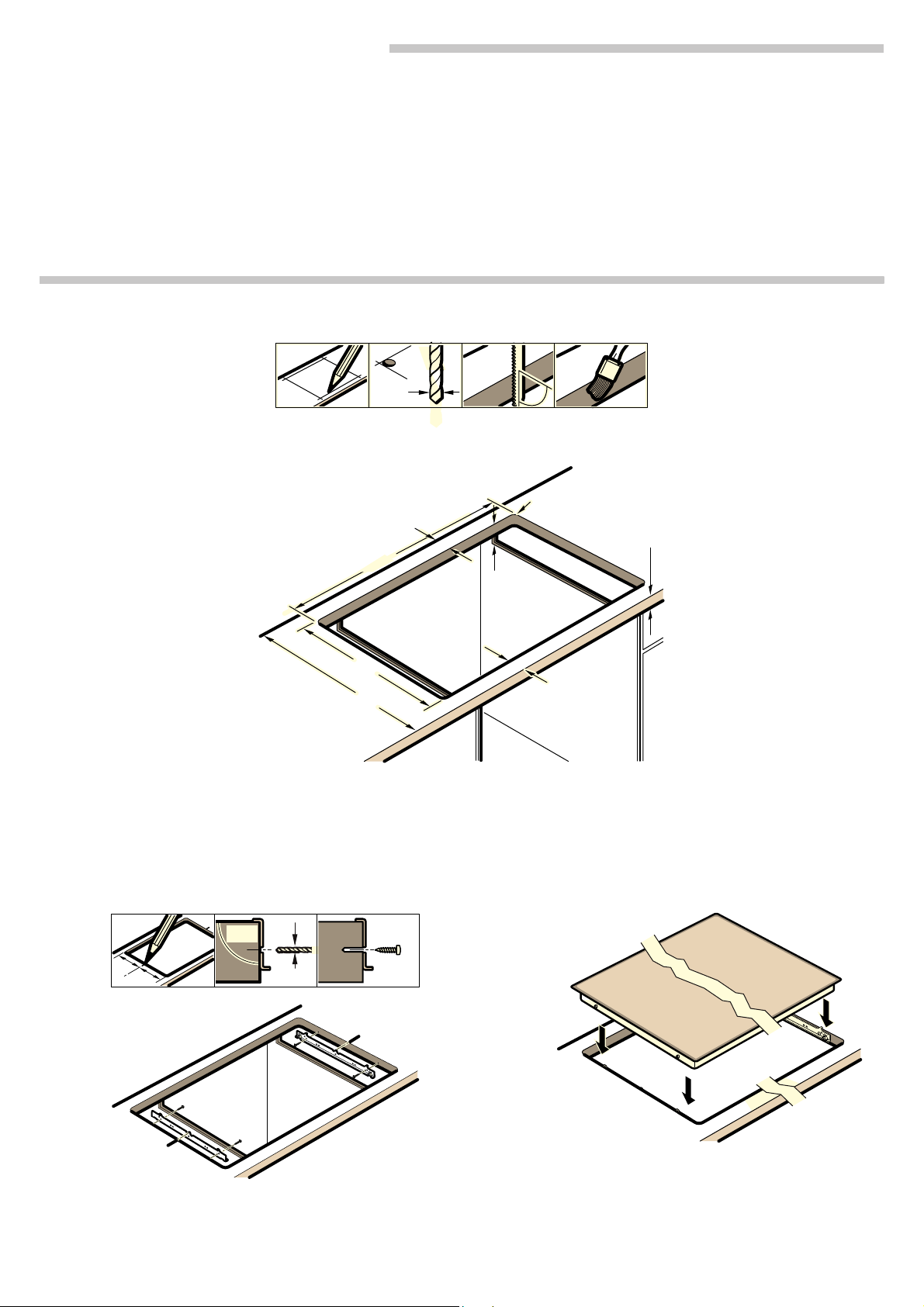
Möbel vorbereiten - Bild 1
Einbaumöbel: mindestens 90°C temperaturbeständig.
Ausschnitt: Mindestabstand zu seitlichen Wänden: 70 mm.
Nach Ausschnittarbeiten Späne entfernen.
Schnittflächen: hitzebeständig versiegeln.
Befestigungsschienen anbringen - Bild 2
Geflieste Arbeitsplatten: untere Schraublöcher verwenden.
Granit oder Marmor Arbeitsplatten: Dübel oder Buchsen für
die Befestigungsschrauben setzen, oder Befestigungsschienen
ankleben.
Kochfeld anschließen und einsetzen - Bild 3
Vor Geräteanschluss Hausinstallation überprüfen.
A: Gerät mit 3-adriger Anschlussleitung: Farbcodierung der
Netzanschlussleitung: grün-gelb = Schutzleiter
Neutral-Leiter, braun = Phase (Aussenleiter).
Auf geeignete Absicherung der Hausinatallation achten. Im
Bedarfsfall durch Leitung für mehrphasigen Anschluss ersetzten. Bei Austausch der Leitung siehe B:
B: Gerät ohne Anschlussleitung: nur nach Anschlussbild
anschließen. Bei Bedarf beiliegende Kupferbrücken montieren.
Netzanschlussleitung: Typ H05 VV-F oder höherwertig. Die gelbgrüne Ader für den Schutzleiter-Anschluss muss geräteseitig
10 mm länger sein, als die anderen Adern.
C: Gerät mit vormontierter5-/6-adriger Anschlussleitung: nur
ein geschulter Kundendienst-Techniker darf die Anschlussleitung austauschen.
Einsetzen: Anschlussleitung nicht einklemmen, nicht über
scharfe Kanten führen. Bei untergebautem Backofen Leitung an
den hinteren Ecken des Backofens zur Anschlussdose führen.
Hinweis: erscheint im Display des Gerätes
angeschlossen. Gerät vom Netz trennen, Anschluss überprüfen.
Geflieste Arbeitsplatten: Fliesenfugen mit Silikonkautschuk
abdichten.
Kochfeld ausbauen: Das Gerät spannungslos machen. Kochfeld von unten herausdrücken.
<, blau = (Null)
—…‹‹ ist es falsch
Preparing the units - Figure 1
Fitting unit: Heat resistant to at least 90°C.
Cut-out: Minimum distance to the side walls: 70 mm.
After the cutting out work is complete, remove the shavings.
Cut surfaces: Seal with heat-resistant material.
Attaching securing rails - Fig. 2
Tiled work surfaces:: Use the lower screw holes.
Granite or marble work surfaces: Insert wall plugs or sockets
for the securing screws or affix securing rails.
Connecting and fitting the hob - Fig. 3
Before connecting the appliance, check the household
installation.
A: Appliance with 3-wire power cable: Colour coding of the
power cord: green-yellow = earth
brown = live (external conductor).
Make sure that the household installation has sufficient fuse or
circuit breaker protection. If necessary, replace with a cable for
a multiphase connection. When replacing the cable, see B:
B: Appliance without power cable: Only connect in accordance
with the connection diagram. If necessary, fit the copper bridge
supplied. Power cord: Type H05 VVF or higher rated. The
yellow/green wire for the PE connection must be 10 mm longer
than the other wires on the appliance side.
C: Appliance with prefitted 5 or 6-wire power cable: The power
cable must only be replaced by a trained after-sales engineer.
Installing: Do not trap the power cable and do not route it over
sharp edges. If the oven is a built-under type, route the cable on
the rear corners of the oven to the socket.
Note: If
been connected correctly. Disconnect the appliance from the
mains and check the connection.
Tiled work surfaces: Seal the tile joints with silicone rubber.
Removing the hob: Disconnect the appliance from the power
supply. Push out the hob from below.
—…‹‹ appears in the display, the appliance has not
<, blue = (zero) neutral,

fr
Þ Notice de montage
Consignes à respecter
Branchement électrique : uniquement par un spécialiste agréé.
Toute erreur de branchement annule la garantie.
Encastrement : uniquement selon les règles de l'art,
l'installateur est responsable en cas de dommages.
Type de raccordement : l'appareil correspond à la classe de
protection I et doit uniquement être utilisé avec un
raccordement à la terre.
Installation : l'installation électrique doit comporter un
interrupteur omnipolaire avec une ouverture de contact d'au
moins 3 mm.
Sous le plan de travail : ne pas installer d'appareil réfrigérant ni
de lave-vaisselle, de four non ventilé ni de lave-linge.
Il est possible d'installer sous le plan de travail un lave-vaisselle
compact/modulaire de la même marque. Épaisseur minimale
du plan de travail 40 mm.
Si un four est encastré sous la table de cuisson, l'épaisseur du
plan de travail peut différer des indications dimensionnelles
contenues dans cette notice. Respectez les consignes de la
notice de montage du four.
Fond de séparation : s'il est possible de toucher le dessous de
la table de cuisson, il est nécessaire de monter un fond de
séparation.
Des fonds de séparation sont en vente dans le commerce
spécialisé comme accessoire.
Si vous utilisez votre propre fond de séparation, la distance
minimale vers le branchement au secteur de l'appareil doit être
de 10 mm.
Plan de travail : plat, horizontal, stable.
Préparation du meuble - fig. 1
Meuble d'encastrement : résistant à une température d'au
moins 90°C.
Découpe : distance minimale vers les parois latérales : 70 mm.
Enlever les copeaux après les travaux de découpe.
Chants de la découpe : les sceller de façon thermostable.
Montage des rails de fixation - fig. 2
Plans de travail carrelés : utiliser les trous de vis inférieurs.
Plan de travail en granit ou en marbre : mettre des chevilles ou
des douilles pour les vis de fixation ou coller les rails de fixation.
Raccordement de la table de cuisson et mise en
place - fig. 3
Avant de raccorder l'appareil, vérifier l'installation domestique.
A : Appareil avec câble de raccordement à 3 fils : code de
couleur du câble de raccordement secteur : vert-jaune = mise à
la terre
extérieur).
Veiller à ce que la protection de l'installation domestique soit
appropriée. En cas de besoin, la remplacer par un câble pour
un raccordement multi-phases. En cas de remplacement du
câble, voir B :
B : Appareil sans câble de raccordement : raccorder
exclusivement selon le schéma de raccordement. En cas de
besoin, monter les ponts en cuivre joints. Câble de
raccordement secteur : type H05 VV-F ou supérieur. Le fil jaunevert pour le raccordement à la terre doit être 10 mm plus long,
côté appareil, que les autres fils.
C : Appareil avec câble de raccordement prémonté à 5/6 fils :
seul un technicien formé du SAV est habilité à remplacer le
câble de raccordement.
Mise en place : Ne pas coincer le câble de raccordement, ne
pas le tirer par-dessus d'arêtes coupantes. En cas de four
installé en-dessous, faire passer le câble aux coins arrière du
four vers la prise de raccordement.
Remarque : Si
celui-ci n'est pas correctement raccordé. Séparer l'appareil du
secteur, vérifier le branchement.
Plans de travail carrelés : Etanchéifier les joints de carrelage
avec un joint en silicone.
Dépose de la table de cuisson : mettre l'appareil hors tension.
Sortir la table de cuisson en la poussant par le bas.
<, bleu = neutre, marron = phase (conducteur
—…‹‹ apparaît dans l'affichage de l'appareil,
it
â Istruzioni per il montaggio
Procedere nel modo seguente
Allacciamento elettrico: solo da parte di un tecnico autorizzato.
In caso di allacciamento scorretto decade la garanzia.
Montaggio: da eseguirsi esclusivamente in modo corretto; in
caso di danni la responsabilità verrà imputata a chi ha eseguito
il montaggio.
Tipo di allacciamento: l'apparecchio rientra nella classe di
protezione I e può essere messo in funzione solo se collegato a
un conduttore di terra.
Installazione: in fase d'installazione è necessario prevedere un
sezionatore universale con un'apertura di contatto di 3 mm.
Sotto l'apparecchio: non è consentito incassare al di sotto
dell'apparecchio frigoriferi, lavastoviglie, forni non ventilati o
lavatrici.
Possono essere montate lavastoviglie modulari/compatte della
stessa marca. Lo spessore del piano di lavoro deve essere di
almeno 40 mm.
Se si installa un forno sotto il piano di cottura, lo spessore del
piano di lavoro può differire dalle dimensioni indicate in questo
manuale. Prestare attenzione alle avvertenze presenti nelle
istruzioni per il montaggio del forno.
Doppiofondo: se è possibile toccare il lato inferiore del piano di
cottura, è necessario montare un doppiofondo.
Richiedere presso un rivenditore specializzato un doppiofondo
come accessorio.
Se si utilizza un proprio doppiofondo, la distanza minima dal
collegamento elettrico dell'apparecchio deve essere di 10 mm.
Piano di lavoro: stabile, in piano e orizzontale.
Preparazione del mobile: figura 1
I mobili da incasso: termostabili almeno fino a 90 °C.
Foro di incasso: distanza minima dalle pareti laterali: 70 mm.
Rimuovere i trucioli dopo i lavori di taglio.
Superfici di taglio: sigillare in modo refrattario.
Applicazione delle guide di fissaggio: figura 2
Piani di lavoro piastrellati: utilizzare il dado inferiore.
Piani di lavoro in granito o marmo: montare tasselli o prese per
le viti di fissaggio oppure applicare delle barre.
Montaggio e allacciamento del piano di cottura:
figura 3
Prima dell'allacciamento dell'apparecchio, controllare l'impianto
domestico.
A: apparecchio con cavo di allacciamento a 3 fili: codificazione
dei colori del cavo di collegamento alla rete elettrica: verde
giallo= conduttore di terra
marrone = fase (conduttore esterno).
Verificare la corretta protezione dell'impianto domestico. In caso
di necessità sostituire con un cavo per allacciamento polifase.
In caso di sostituzione del cavo vedere B:
B: apparecchio senza cavo di allacciamento: attenersi sempre
allo schema di collegamento. Se occorre, montare i ponticelli in
rame forniti in dotazione. Cavo di collegamento alla rete
elettrica: modello H05 VV-F o superiore. Il filo giallo-verde per il
collegamento del conduttore di terra, dal lato dell'apparecchio,
deve essere 10 mm più lungo degli altri.
C: apparecchio con cavo di allacciamento a 5/6 fili
precedentemente montato: le sostituzioni devono essere
effettuate esclusivamente da personale tecnico adeguatamente
istruito dal servizio assistenza tecnica.
Inserimento: fare in modo che il cavo non rimanga incastrato e
non passi su spigoli vivi. In caso di forni sottostanti, portare il
cavo alla presa di collegamento facendolo passare dall'angolo
posteriore del forno.
Avvertenza: se sul display dell'apparecchio compare
significa che non è stato collegato correttamente. Staccare
l'apparecchio dalla rete di alimentazione e controllare
l'allacciamento.
Piani di lavoro piastrellati: chiudere a tenuta le fughe tra le
piastrelle mediante gomma siliconica.
Smontaggio del piano di cottura: scollegare l'apparecchio
dalla rete elettrica. Estrarre il piano di cottura spingendolo dal
basso.
<, blu = (zero) conduttore neutro,
—…‹‹
 Loading...