

Bosch NIN-63013-A3, NIN-63013-A3S, NIN-63023-A3, NIN-63023-A3S, NIN-73013-A10A Operation Manual
...
Camera Browser Interface
DINION / FLEXIDOME IP starlight 6000/7000
en Software manual


Camera Browser
Interface
Table of contents
Table of Contents | en 3
1
1.1 System requirements 11
1.2 Establishing the connection 11
1.2.1 Password protection in camera 12
1.3 Protected network 12
2
2.1 Live page 13
2.2 Playback 13
2.3 Configuration 13
3
3.1 Live page 15
3.1.1 Image selection 15
3.1.2 Intelligent Tracking 15
3.1.3 Digital I/O 15
3.1.4 Recording status 16
3.1.5 Saving snapshots 16
3.1.6 Recording live video 16
3.1.7 Full-screen display 17
3.1.8 Storage, CPU and network status 17
3.1.9 Status icons 17
3.1.10 Audio communication 18
3.2 Playback 20
3.2.1 Selecting the recording stream 20
3.2.2 Searching for recorded video 20
3.2.3 Exporting recorded video 20
3.2.4 Controlling playback 21
4
4.1 Identification 23
4.1.1 Naming 23
4.1.2 ID 23
4.1.3 iSCSI Initiator extension 23
4.2 User management 24
4.3 Date/Time 25
Bosch Security Systems 2016.09 | v1.632 | AM18-Q0718
Browser connection 11
System overview 13
Operation via the browser 15
General settings 23

4 en | Table of Contents
Camera Browser
Interface
4.3.1 Date format 25
4.3.2 Device date / Device time 25
4.3.3 Device time zone 25
4.3.4 Daylight saving time 25
4.3.5 Time server IP address 26
4.3.6 Time server type 26
4.4 Display Stamping 28
4.4.1 Camera name stamping 28
4.4.2 Logo stamping 28
4.4.3 Time stamping 28
4.4.4 Display milliseconds 28
4.4.5 Alarm mode stamping 29
4.4.6 Alarm message 29
4.4.7 Transparent background 29
4.4.8 Video authentication 29
4.5 GB/T 28181 29
5
Web Interface 31
5.1 Appearance 31
5.1.1 Website language 31
5.1.2 Company logo 31
5.1.3 Device logo 31
5.1.4 Show VCA metadata 31
5.1.5 Show VCA trajectories 31
5.1.6 Show overlay icons 32
5.1.7 Latency mode 32
5.1.8 JPEG size, interval and quality 32
5.2 LIVE Functions 33
5.2.1 Transmit audio 33
5.2.2 Lease time [s] 33
5.2.3 Show alarm inputs 33
5.2.4 Show alarm outputs 33
5.2.5 Allow snapshots 33
5.2.6 Allow local recording 34
5.2.7 I-frames-only stream 34
5.2.8 Show pre-positions 34
2016.09 | v1.632 | AM18-Q0718 Bosch Security Systems

Camera Browser
Interface
Table of Contents | en 5
5.2.9 Show Intelligent Tracking 34
5.2.10 Path for JPEG and video files 34
5.2.11 Video file format 34
6
Camera 35
6.1 Installer Menu 35
6.1.1 Application variant 35
6.1.2 Base frame rate 35
6.1.3 Camera LED 35
6.1.4 Rotate image 35
6.1.5 Mirror image 35
6.1.6 Menu button 36
6.1.7 Analog output 36
6.1.8 Reboot device 36
6.1.9 Factory defaults 36
6.1.10 Lens Wizard 36
6.1.11 Positioning 36
6.2 Lens Wizard 37
6.3 Picture settings – Scene mode 38
6.3.1 Current mode 38
6.3.2 Mode ID 38
6.3.3 Copy mode to 38
6.3.4 Restore Mode Defaults 38
6.3.5 Scene mode factory defaults 38
6.4 Picture settings – Color 40
6.4.1 Picture adjustments 40
6.4.2 White balance 40
6.5 Picture settings – ALC 42
6.5.1 ALC mode 42
6.5.2 ALC level 42
6.5.3 Saturation (av-pk) 42
6.5.4 Maximum gain level 42
6.5.5 Exposure/frame rate 42
6.5.6 Day/night 43
6.6 Picture settings – Enhance 44
6.6.1 Sharpness level 44
Bosch Security Systems 2016.09 | v1.632 | AM18-Q0718

6 en | Table of Contents
Camera Browser
Interface
6.6.2 Backlight Compensation 44
6.6.3 Contrast enhancement 44
6.6.4 Intelligent DNR 44
6.6.5 Intelligent defog 45
6.7 Picture settings – Scene mode scheduler 46
6.8 Encoder Settings 47
6.9 Privacy Masks 48
6.10 Audio 49
6.10.1 Select input 49
6.10.2 Adjust level 49
6.10.3 Recording format 49
6.11 Pixel Counter 50
7
Encoder Settings 51
7.1 Introduction to encoder settings 51
7.2 Encoder Profile 52
7.2.1 Pre-defined profiles 52
7.2.2 Changing a profile 52
7.2.3 Profile name 52
7.2.4 Target bit rate 53
7.2.5 Maximum bit rate 53
7.2.6 Encoding interval 53
7.2.7 Standard definition video resolution 53
7.2.8 Expert Settings 54
7.2.9 Default 55
7.3 Encoder Streams 56
7.3.1 H.264 settings 56
7.3.2 JPEG stream 56
7.4 Encoder Regions 57
8
Recording 58
8.1 Introduction to recording 58
8.2 Storage Management 59
8.2.1 Device manager 59
8.2.2 Recording media 59
8.2.3 Activating and configuring storage media 60
8.2.4 Formatting storage media 60
2016.09 | v1.632 | AM18-Q0718 Bosch Security Systems

Camera Browser
Interface
Table of Contents | en 7
8.2.5 Deactivating storage media 61
8.3 Recording Profiles 62
8.3.1 Recording track selection 62
8.3.2 Standard recording 63
8.3.3 Alarm recording 63
8.4 Maximum Retention Time 65
8.5 Recording Scheduler 66
8.5.1 Weekdays 66
8.5.2 Holidays 66
8.5.3 Profile names 67
8.5.4 Activate recording 67
8.5.5 Recording status 67
8.6 Recording Status 67
9
Alarm 68
9.1 Alarm Connections 68
9.1.1 Connect on alarm 68
9.1.2 Number of destination IP address 68
9.1.3 Destination IP address 68
9.1.4 Destination password 68
9.1.5 Video transmission 69
9.1.6 Stream 69
9.1.7 Remote port 69
9.1.8 Video output 69
9.1.9 Decoder 70
9.1.10 SSL encryption 70
9.1.11 Auto-connect 70
9.1.12 Audio 70
9.2 Video Content Analysis (VCA) 71
9.3 Audio Alarm 72
9.3.1 Audio alarm 72
9.3.2 Name 72
9.3.3 Signal Ranges 72
9.3.4 Threshold 72
9.3.5 Sensitivity 72
9.4 Alarm E-Mail 73
Bosch Security Systems 2016.09 | v1.632 | AM18-Q0718

8 en | Table of Contents
Camera Browser
Interface
9.4.1 Send alarm e-mail 73
9.4.2 Mail server IP address 73
9.4.3 SMTP user name 73
9.4.4 SMTP password 73
9.4.5 Format 73
9.4.6 Image size 73
9.4.7 Attach JPEG from camera 74
9.4.8 Destination address 74
9.4.9 Sender name 74
9.4.10 Test e-mail 74
9.5 Alarm Task Editor 75
10
Setting up VCA 76
10.1 VCA - Silent VCA 76
10.2 VCA - Profiles 76
10.2.1 Aggregation time [s] 76
10.2.2 Analysis type 77
10.2.3 Tamper detection 77
10.3 VCA - Scheduled 81
10.3.1 Weekdays 81
10.3.2 Holidays 81
10.4 VCA - Event triggered 83
10.4.1 Trigger 83
10.4.2 Trigger active 83
10.4.3 Trigger inactive 83
10.4.4 Delay [s] 83
11
Interfaces 84
11.1 Alarm input 84
11.1.1 Name 84
11.1.2 Action 84
11.2 Alarm output 85
11.2.1 Idle state 85
11.2.2 Operating mode 85
11.2.3 Output follows 85
11.2.4 Output name 85
11.2.5 Toggle output 85
2016.09 | v1.632 | AM18-Q0718 Bosch Security Systems

Camera Browser
Interface
Table of Contents | en 9
11.3 COM1 86
11.3.1 Serial port function 86
11.3.2 Camera ID 86
11.3.3 Baud rate 86
11.3.4 Data bits 86
11.3.5 Stop bits 86
11.3.6 Parity check 86
11.3.7 Interface mode 86
12
Network 87
12.1 Network Access 87
12.1.1 Automatic IPv4 assignment 87
12.1.2 IP V4 address 87
12.1.3 IP V6 address 88
12.1.4 DNS server address 88
12.1.5 Video transmission 88
12.1.6 HTTP browser port 88
12.1.7 HTTPS browser port 88
12.1.8 HSTS 89
12.1.9 RCP+ port 1756 89
12.1.10 Telnet support 89
12.1.11 Interface mode ETH 89
12.1.12 Network MSS [Byte] 89
12.1.13 iSCSI MSS [Byte] 90
12.1.14 Network MTU [Byte] 90
12.2 DynDNS 91
12.2.1 Enable DynDNS 91
12.2.2 Provider 91
12.2.3 Host name 91
12.2.4 User name 91
12.2.5 Password 91
12.2.6 Force registration now 91
12.2.7 Status 92
12.3 Advanced 93
12.3.1 Cloud-based Services 93
12.3.2 RTSP port 93
Bosch Security Systems 2016.09 | v1.632 | AM18-Q0718

10 en | Table of Contents
Camera Browser
Interface
12.3.3 Authentication (802.1x) 93
12.3.4 TCP metadata input 93
12.4 Network Management 94
12.4.1 SNMP 94
12.4.2 UPnP 94
12.4.3 Quality of Service 95
12.5 Multicast 96
12.5.1 Enable 96
12.5.2 Multicast Address 96
12.5.3 Port 97
12.5.4 Streaming 97
12.5.5 Multicast packet TTL 97
12.6 Image Posting 98
12.6.1 JPEG posting 98
12.6.2 Face Detection 98
12.7 Accounts 100
12.8 IPv4 Filter 101
13
Service 102
13.1 Maintenance 102
13.1.1 Update server 102
13.1.2 Firmware 102
13.1.3 Upload History 103
13.1.4 Configuration 103
13.1.5 Maintenance log 103
13.2 Licenses 104
13.3 Certificates 104
13.3.1 Usage list 104
13.3.2 File list 105
13.4 System Overview 105
14
Appendices 106
14.1 Copyright notices 106
2016.09 | v1.632 | AM18-Q0718 Bosch Security Systems

Camera Browser
Interface
Browser connection | en 11
1
1.1
Browser connection
A computer with Microsoft Internet Explorer is used to receive
live images, control the unit, and replay stored sequences. The
unit is configured over the network using the browser.
System requirements
Our recommendations are:
– Computer with Dual core HyperThreading processor or
better
– Graphic card with performance that matches or is better
than the resolution of the camera
– Windows 7 or later operating system
– Network access
– Internet Explorer version 11 or later
– or –
Application software, for example, Video Security Client,
Bosch Video Client or Bosch Video Management System.
Note:
To see live images in your browser it might be necessary to
download and install the MPEG-ActiveX from the Bosch
download store.
1.2
Bosch Security Systems 2016.09 | v1.632 | AM18-Q0718
Establishing the connection
The unit must have a valid IP address to operate on your
network and a compatible subnet mask.
By default, DHCP is pre-set at the factory to On plus Link-Local
so a DHCP server assigns an IP address or, if no DHCP server is
available, a link-local address (auto-IP) is assigned within the
range 169.254.1.0 to 169.254.254.255.
(You can use IP Helper or Configuration Manager to find the IP
address.)
1. Start the Web browser.
2. Enter the IP address of the unit as the URL.

12 en | Browser connection
3. During initial installation, confirm any security questions
that appear.
Note:
If you cannot connect, the unit may have reached its maximum
number of connections. Depending on the device and network
configuration, each unit can have up to 50 web browser
connections, or up to 100 connections via Bosch Video Client or
Bosch Video Management System.
Camera Browser
Interface
1.2.1
1.3
Password protection in camera
A unit offers the option of limiting access across various
authorization levels. If the unit is password-protected, a
message to enter the password appears.
1. Enter the user name and the associated password in the
appropriate fields.
2. Click OK. If the password is correct, the desired page is
displayed.
Protected network
If a RADIUS server is used for network access control (802.1x
authentication), the unit must be configured first. To configure
the unit, connect it directly to a computer using a network cable
and configure the two parameters, Identity and Password. Only
after these have been configured can communication with the
unit via the network occur.
2016.09 | v1.632 | AM18-Q0718 Bosch Security Systems
Camera Browser
Interface
System overview | en 13
2
System overview
When a connection is established, the Live page is initially
displayed.
The application bar displays the following icons:
Live To view the live video stream, click
this icon.
Playback To play back recorded sequences,
click this icon.
This link is only visible if a storage
medium has been configured for
recording. (With VRM recording this
option is not active.)
Configuration To configure the unit, click this icon.
Links To navigate to the Bosch download
store, click this icon.
To get context sensitive help for a
particular page, click this icon.
2.1
2.2
2.3
Bosch Security Systems 2016.09 | v1.632 | AM18-Q0718
Live page
The Live page is used to display the live video stream and
control the unit.
Playback
The Playback page is used for playing back recorded sequences.
Configuration
The Configuration page is used to configure the unit and the
application interface.

14 en | System overview
Making Changes
Each configuration screen shows the current settings. You can
change the settings by entering new values or by selecting a
predefined value from a list field.
Not every page has a Set button. Changes to pages without a
Set button are set immediately. If a page does show a Set
button, you must click the Set button for a change to take
effect.
Notice!
Save each change with the associated Set button.
Clicking the Set button saves the settings only in the current
field. Changes in any other fields are ignored.
Some changes only take effect after the unit is rebooted. In this
case, the Set button changes to Set and Reboot.
1. Make the desired changes.
2. Click the Set and Reboot button. The camera reboots and
the changed settings are activated.
Camera Browser
Interface
2016.09 | v1.632 | AM18-Q0718 Bosch Security Systems

Camera Browser
Interface
Operation via the browser | en 15
3
3.1
3.1.1
3.1.2
Operation via the browser
Live page
After the connection is established, the Live page is initially
displayed. It shows the live video image on the right of the
browser window. Depending on the configuration, various text
overlays may be visible on the live video image.
Other information may also be shown next to the live video
image. The items shown depend on the settings on the 'Live'
functions page.
Image selection
To view a live stream:
1. On the left side of the browser, expand the Connection
group if necessary.
2. Click the Stream drop-down arrow to see the options.
3. Select the stream you wish to view.
Intelligent Tracking
For cameras with the ability to track movement, options for
tracking objects within the region of interest are displayed in
the Intelligent tracking panel.
When on, the tracking icon
together with the lines that track moving objects.
Select Off, Auto or Click. If Click is selected, use the mouse to
click on an object to track it.
3.1.3
Bosch Security Systems 2016.09 | v1.632 | AM18-Q0718
Digital I/O
(only for cameras with alarm connections)
Depending on the configuration of the unit, the alarm input and
the output are displayed next to the image. Expand the Digital
I/O group if necessary.
is displayed on the image
16 en | Operation via the browser
The alarm symbol is for information and indicates the status of
an alarm input:
– The symbol lights when the input alarm is active.
The alarm output allows the operation of an external device (for
example, a light or a door opener).
– To activate the output, click the checkmark symbol.
– The symbol lights when the output is activated.
Camera Browser
Interface
3.1.4
3.1.5
3.1.6
Recording status
The hard drive icon below the live camera image changes
during an automatic recording. The icon lights up and displays a
moving graphic to indicate a running recording. If no recording
is taking place, a static icon is displayed.
Saving snapshots
Individual images from the displayed live video stream can be
saved locally in JPEG format on the computer's hard drive.
– Click the photo camera icon to save a single image.
– The storage location depends on the configuration of
the camera.
Recording live video
Video sequences from the displayed live video stream can be
saved locally on the computer's hard drive. The sequences are
recorded at the resolution specified in the encoder
configuration. The storage location depends on the
configuration of the camera.
1. Click the recording icon
– Saving begins immediately. The red dot on the icon
indicates that a recording is in progress.
2. Click the recording icon again to stop recording.
2016.09 | v1.632 | AM18-Q0718 Bosch Security Systems
to record video sequences.
Camera Browser
Interface
Operation via the browser | en 17
3.1.7
3.1.8
Full-screen display
Click the full-screen icon
full-screen mode; press Esc on the keyboard to return to the
normal viewing window.
to view the selected stream in
Storage, CPU and network status
When accessing the unit with a browser, the local storage,
processor and network status icons are shown in the upper
right of the window.
When a local storage card is available, the memory card icon
changes color (green, orange or red) to indicate the local
storage activity. If you hover over this icon with the mouse the
storage activity is shown as a percentage.
If you hover over the middle icon, the CPU load is shown.
If you hover over the right-hand icon, the network load is shown.
This information can help with problem solving or when fine
tuning the unit. For example:
– if the storage activity is too high, change the recording
profile,
– if the CPU load is too big, change the VCA settings,
– if the network load is too big, change the encoder profile to
reduce bitrate.
3.1.9
Bosch Security Systems 2016.09 | v1.632 | AM18-Q0718
Status icons
Various overlays in the video image provide important status
information. The overlays provide the following information:
Decoding error
The frame might show artifacts due to decoding errors.
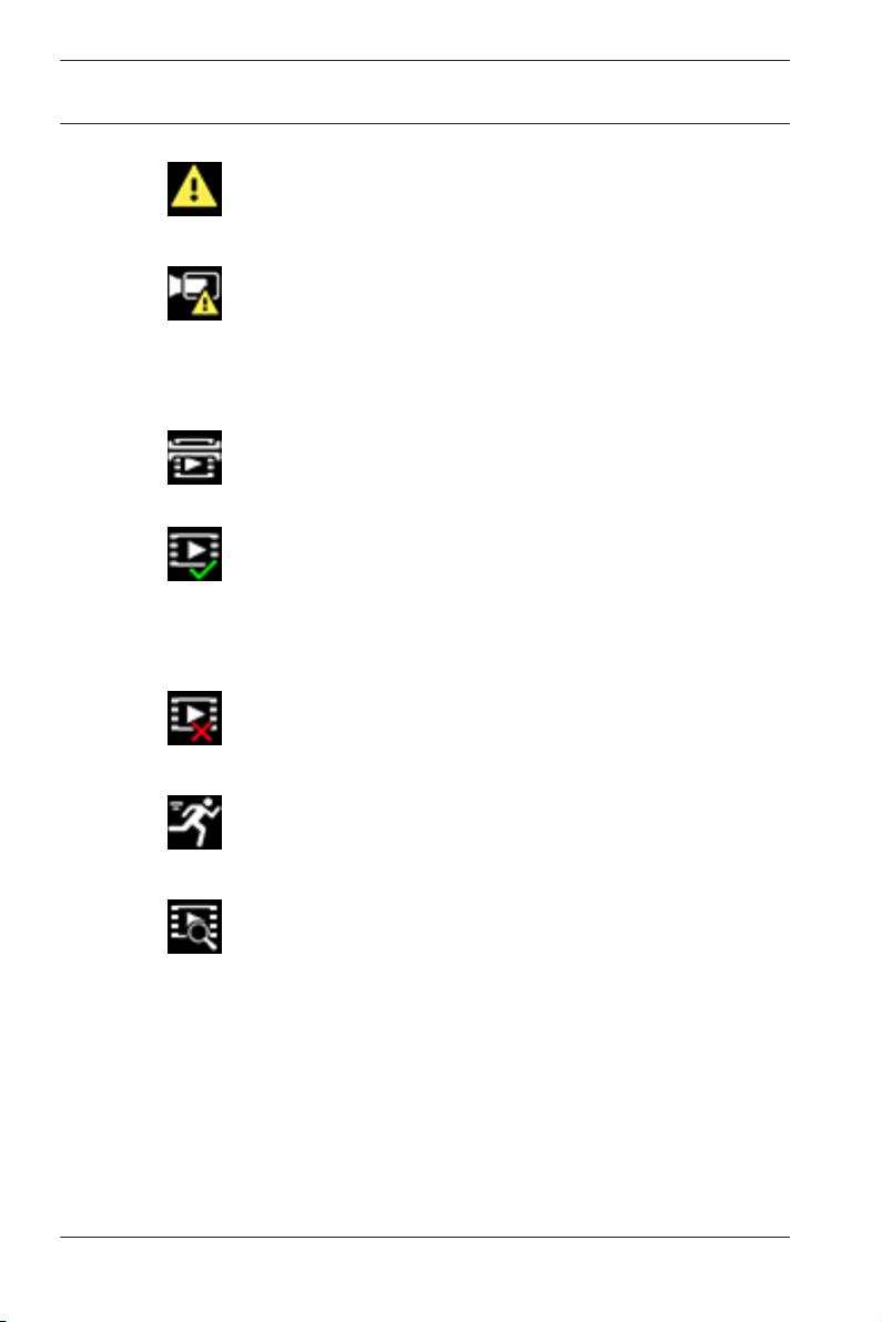
18 en | Operation via the browser
Alarm flag
Indicates that an alarm has occurred.
Communication error
A communication error, such as a connection failure to the
storage medium, a protocol violation or a timeout, is indicated
by this icon.
Gap
Indicates a gap in the recorded video.
Watermark valid
The watermark set on the media item is valid. The color of the
check mark changes according to the video authentication
method that has been selected.
Camera Browser
Interface
Watermark invalid
Indicates that the watermark is not valid.
Motion alarm
Indicates that a motion alarm has occurred.
Storage discovery
Indicates that recorded video is being retrieved.
3.1.10
Audio communication
Audio can be sent and received via the Live page if the unit and
the computer support audio.
1. Press and hold the F12 key on the keyboard to send an
audio signal to the unit.
2. Release the key to stop sending audio.
2016.09 | v1.632 | AM18-Q0718 Bosch Security Systems

Camera Browser
Interface
All connected users receive audio signals sent from the unit but
only the user who first pressed the F12 key can send audio
signals; others must wait for the first user to release the key.
Operation via the browser | en 19
Bosch Security Systems 2016.09 | v1.632 | AM18-Q0718

20 en | Operation via the browser
Camera Browser
Interface
3.2
3.2.1
3.2.2
Playback
Click Playback in the application bar to view, search or
export recordings. This link is only visible if a direct iSCSI or
memory card has been configured for recording. (With VRM
recording this option is not active.)
The panel on the left has four groups:
– Connection
– Search
– Export
– Track list
Selecting the recording stream
On the left side of the browser, expand the Connection group if
necessary.
To view a recording stream:
1. Click the Recording drop-down arrow to see the options.
2. Select recording stream 1 or 2.
Searching for recorded video
On the left side of the browser, expand the Search group if
necessary.
1. To limit the search to a particular time range, enter the date
and times for the start and stop points.
2. Select an option from the drop-down box to define a search
parameter.
3. Click Start Search.
4. The results are shown.
5. Click a result to play it back.
6. Click Back to define a new search.
3.2.3
2016.09 | v1.632 | AM18-Q0718 Bosch Security Systems
Exporting recorded video
On the left side of the browser, expand the Export group if
necessary.

Camera Browser
Interface
1. Select a track in the track list or in the search results (or
2. The start and stop date and time are filled-in for the
3. In the Time lapse drop-down box, select the original or a
4. In the Location drop-down box, select a target.
5. Click Export to save the video track.
Note:
The target server address is set on the Network / Accounts
page.
Operation via the browser | en 21
click on the timeline below the video window and drag the
buttons to mark the sequence you want to export).
selected track. If required, change the times.
condensed speed.
3.2.4
Controlling playback
The time bar below the video image allows quick orientation.
The time interval associated with the sequence is displayed in
the bar in blue. Arrows indicate the position of the image
currently being played back within the sequence. The time code
is displayed on the left below the time bar.
The time bar offers various options for navigation in and
between sequences.
– If required, click in the bar at the point in time at which the
playback should begin.
– Change the time interval displayed by clicking the plus or
minus icons or use the mouse scroll wheel. The display can
span a range from six months to one minute.
– Click the alarm jump buttons to go from one alarm event to
the next or to the previous one. Red bars indicate the
points in time where alarms were triggered.
Controls
Control playback by means of the buttons below the video
image.
The buttons have the following functions:
– Start/Pause playback
Bosch Security Systems 2016.09 | v1.632 | AM18-Q0718

22 en | Operation via the browser
– Select the playback (forward or backward) speed using the
speed regulator
– Step forward or backward frame-by-frame when paused
(small arrows)
Camera Browser
Interface
2016.09 | v1.632 | AM18-Q0718 Bosch Security Systems

Camera Browser
Interface
General settings | en 23
4
4.1
4.1.1
4.1.2
4.1.3
General settings
Identification
Naming
Assign a unique name to assist in identification. This name
simplifies the management of multiple devices in more extensive
systems.
The name is used for remote identification, for example, in the
event of an alarm. Choose a name that makes it as easy as
possible to identify the location unambiguously.
ID
Each device should be assigned a unique identifier that can be
entered here as an additional means of identification.
iSCSI Initiator extension
Add text to an initiator name to make identification easier in
large iSCSI systems. This text is added to the initiator name,
separated from it by a full stop. (You can see the initiator name
in the System Overview page.)
Bosch Security Systems 2016.09 | v1.632 | AM18-Q0718

24 en | General settings
Camera Browser
Interface
4.2
User management
User management prevents unauthorized access to the device
by using different authorization levels to limit access. You can
define and change a password for each authorization level if you
have first logged in and set a password for service.
User management allows free assignment of user names. Each
user can be assigned a user group with a corresponding
authorization level.
Authorization levels
The device has three authorization levels: service, user, and live.
– service is the highest authorization level. Entering the
correct password gives access to all the functions and
allows all configuration settings to be changed.
– user is the middle authorization level. At this level you can
operate the device, play back recordings, and also control
camera, for example, but you cannot change the
configuration.
– live is the lowest authorization level. At this level you can
only view the live video image and switch between the
different live image displays.
Add user to group
To add new user to a group, click Add.
In the text box, enter a name for the new user.
For Group, select the appropriate authorization level.
Enter a password and confirm it by typing the same password
again. The maximum password text length is 19 characters and
no special characters are allowed.
Change password
To change a password, click the pencil icon to the right of the
column Type for the appropriate User name.
Enter a password and confirm it by typing the same password
again. The maximum password text length is 19 characters and
no special characters are allowed.
2016.09 | v1.632 | AM18-Q0718 Bosch Security Systems

Camera Browser
Interface
General settings | en 25
4.3
4.3.1
4.3.2
Date/Time
Date format
Select the required date format.
Device date / Device time
If there are multiple devices operating in your system or
network, it is important to synchronize their internal clocks. For
example, it is only possible to identify and correctly evaluate
simultaneous recordings when all devices are operating on the
same time.
1. Enter the current date. Since the device time is controlled
by the internal clock, it is not necessary to enter the day of
the week – it is added automatically.
2. Enter the current time or click Sync to PC to apply the
system time from your computer to the device.
Note:
It is important that the date/time is correct for recording. An
incorrect date/time setting could prevent correct recording.
4.3.3
4.3.4
Bosch Security Systems 2016.09 | v1.632 | AM18-Q0718
Device time zone
Select the time zone in which the system is located.
Daylight saving time
The internal clock can switch automatically between normal and
daylight saving time (DST). The unit already contains the data
for DST switch-overs for many years in advance. If the date, time
and zone have been set up correctly, a DST table is
automatically created.
If you decide to create alternative daylight saving time dates by
editing the table, note that values occur in linked pairs (DST
start and end dates).

26 en | General settings
First, check the time zone setting. If it is not correct, select the
appropriate time zone and click Set.
1. Click Details to edit the DST table.
2. Select the region or the city which is closest to the
system's location from the list box below the table.
3. Click Generate to fill the table with the preset values from
the unit.
4. Click one of the entries in the table to make changes. The
entry is highlighted.
5. Click Delete to remove the entry from the table.
6. Choose other values from the list boxes under the table, to
change the selected entry. Changes are immediate.
7. If there are empty lines at the bottom of the table, for
example after deletions, add new data by marking the row
and selecting values from the list boxes.
8. When finished, click OK to save and activate the table.
Camera Browser
Interface
4.3.5
4.3.6
2016.09 | v1.632 | AM18-Q0718 Bosch Security Systems
Time server IP address
The unit can receive the time signal from a time server using
various time server protocols and then use it to set the internal
clock. The device polls the time signal automatically once every
minute.
Enter the IP address of a time server.
To use the time signal from the DHCP server, check the
Overwrite by DHCP box.
Time server type
Select the protocol that is supported by the selected time
server:
– It is recommended to select the SNTP protocol protocol.
This protocol provides high accuracy and is required for
special applications and future function extensions.
– Select Time protocol if the server uses the RFC 868
protocol.
– Select TLS protocol if the server uses the RFC 5246
protocol.

Camera Browser
Interface
– Select Off if no time server is used.
General settings | en 27
Bosch Security Systems 2016.09 | v1.632 | AM18-Q0718

28 en | General settings
Camera Browser
Interface
4.4
4.4.1
4.4.2
4.4.3
Display Stamping
Various overlays or stamps in the video image provide important
supplementary information. These overlays can be enabled
individually and arranged on the image in a clear manner.
Camera name stamping
Select the position of the camera name overlay in the dropdown box. It can be displayed at the Top, at the Bottom, or at a
position of choice using the Custom option, or it can be set to
Off for no overlay information.
If the Custom option is selected, enter values in the X and Y
position fields.
Logo stamping
To place a logo on the image, select and upload an
uncompressed .bmp file with a maximum size of 128x128 pixels
and 256 colors to the camera. Its position on the image can then
be selected.
Time stamping
Select the position of the time and date overlay in the dropdown box. It can be displayed at the Top, at the Bottom, or at a
position of choice using the Custom option, or it can be set to
Off for no overlay information.
If the Custom option is selected, enter values in the X and Y
position fields.
4.4.4
2016.09 | v1.632 | AM18-Q0718 Bosch Security Systems
Display milliseconds
If necessary, display milliseconds for Time stamping. This
information can be useful for recorded video images; however, it
does increase the processor's computing time. Select Off if
displaying milliseconds is not needed.

Camera Browser
Interface
General settings | en 29
4.4.5
4.4.6
4.4.7
4.4.8
Alarm mode stamping
Select On in the drop-down box for a text message to be
displayed in the event of an alarm. It can be displayed at a
position of choice using the Custom option, or it can be set to
Off for no overlay information.
If the Custom option is selected, enter values in the X and Y
position fields.
Alarm message
Enter the message to be displayed on the image in the event of
an alarm. The maximum text length is 31 characters.
Transparent background
Check this box to make the stamp on the image transparent.
Video authentication
Select a method for verifying the integrity of the video in the
Video authentication drop-down box.
If you select Watermarking all images are marked with an icon.
The icon indicates if the sequence (live or saved) has been
manipulated.
If you want to add a digital signature to the transmitted video
images to ensure their integrity, select one of the cryptographic
algorithms for this signature.
Enter the interval (in seconds) between insertions of the digital
signature.
4.5
Bosch Security Systems 2016.09 | v1.632 | AM18-Q0718
GB/T 28181
This page allows you to set the parameters for conformance to
the GB/T 28181 national standard “Security and protection
video monitoring network system for information transport,
switch and control”. This standard is specifically for China.

en | General settings
30
Camera Browser
Interface
Enable
Select this checkbox to enable the system to use the other
parameters on this page in accordance with the GB/T 28181
national standard.
H.264 elementary stream
Select this checkbox to select or to enable the H.264 elementary
stream.
Registration timeout
Enter a value (in milliseconds) for the registration timeout. The
default is 3600.
Heartbeat timeout
Enter the value (in seconds) for the heartbeat timeout. The
default is 15.
Server ID
Enter the ID of the server.
Server IP address
Enter the server IP address.
Device ID
Enter the ID of the device.
Device port
Enter the number of the device port. The default is 5060.
Password
Enter the appropriate password.
Alarm device ID
Enter the ID of the alarm device.
2016.09 | v1.632 | AM18-Q0718 Bosch Security Systems
 Loading...