

Page 1
Gas Cooktop
Installation Manual
NGM5056UC, NGM5656UC, NGM8056UC, NGM8656UC,
NGMP056UC, NGMP656UC
Page 2
Table of Contents
Use and care manual
Safety Definitions .......................................................... 2
IMPORTANT SAFETY INSTRUCTIONS ........................ 3
Gas Appliance Safety .......................................................... 3
Propane Gas Installation ..................................................... 4
Equipment and Usage Safety Requirements .................. 4
Appliance Handling Safety ................................................. 5
Safety Codes and Standards ............................................. 5
State of California Proposition 65 Warning: .................... 5
Electric Safety ....................................................................... 5
High Altitude Installation ..................................................... 5
Before You Begin .......................................................... 6
Tools and Parts Needed ..................................................... 6
Parts Included ....................................................................... 6
General Information ............................................................. 6
7KLV%RVFK$SSOLDQFHLVPDGHE\
%6++RPH$SSOLDQFHV&RUSRUDWLRQ
0DLQ6WUHHW6XLWH
,UYLQH&$
4XHVWLRQV"
Preparation ............................................................................ 6
Installation Procedure .................................................. 8
Prepare the Countertop ...................................................... 8
Seal the Cooktop with Foam Tape ................................... 8
Install the Cooktop ............................................................... 9
Connect Gas Supply ........................................................... 9
Connect Electrical Supply ............................................... 10
Burner Cap and Burner Base Placement ..................... 10
Install Burner Grates ......................................................... 12
Check the Installation ....................................................... 12
Service ......................................................................... 13
Before Calling Service ..................................................... 13
ZZZERVFKKRPHFRPXV
:HORRNIRUZDUGWRKHDULQJIURP\RX
Safety Definitions
9 WARNING
This indicates that death or serious injuries may
occur as a result of non-observance of this warning.
9 CAUTION
This indicates that minor or moderate injuries may
occur as a result of non-observance of this warning.
NOTICE: This indicates that damage to the appliance or property may occur as a result of non-compliance with this advisory.
Note: This alerts you to important information and/or tips.
2
Page 3
9 IMPORTANT SAFETY INSTRUCTIONS
READ AND SAVE THESE INSTRUCTIONS
IMPORTANT SAFETY I NST RUCT I ONSREAD AND SAVE THESE INSTRUCTIONS
Gas Appliance Safety
:$51,1*,IWKHLQIRUPDWLRQLQWKHVHLQVWUXFWLRQV
LVQRWIROORZHGH[DFWO\DILUHRUH[SORVLRQPD\
UHVXOWFDXVLQJSURSHUW\GDPDJHSHUVRQDOLQMXU\
RUGHDWK
²
'RQRWVWRUHRUXVHJDVROLQHRURWKHUIODPPDEOH
YDSRUVDQGOLTXLGVLQWKHYLFLQLW\RIWKLVRUDQ\
RWKHUDSSOLDQFH
²
:+$772'2,)<2860(//*$6
'RQRWWU\WROLJKWDQ\DSSOLDQFH
'RQRWWRXFKDQ\HOHFWULFDOVZLWFK
'RQRWXVHDQ\SKRQHLQ\RXUEXLOGLQJ
,PPHGLDWHO\FDOO\RXUJDVVXSSOLHUIURPD
QHLJKERU·VSKRQH)ROORZWKHJDVVXSSOLHU·V
LQVWUXFWLRQV
,I\RXFDQQRWUHDFK\RXUJDVVXSSOLHUFDOO
WKHILUHGHSDUWPHQW
,QVWDOODWLRQDQGVHUYLFHPXVWEHSHUIRUPHG
²
E\DTXDOLILHGLQVWDOOHUVHUYLFHDJHQF\RUWKH
JDVVXSSOLHU
3
Page 4

9 IMPORTANT SAFETY INSTRUCTIONS
READ AND SAVE THESE INSTRUCTIONS
IMPORTANT: SAVE THESE INSTRUCTIONS FOR THE LOCAL ELECTRICAL INSPECTOR’S USE.
INSTALLER: LEAVE THESE INSTRUCTIONS WITH THE UNIT FOR THE OWNER.
OWNER: PLEASE RETAIN THESE INSTRUCTIONS FOR FUTURE REFERENCE.
WARNING
When properly cared for, your new appliance has been
designed to be safe and reliable. Read all instructions
carefully before use. These precautions will reduce the
risk of burns, electric shock, fire and injury to persons.
When using kitchen appliances, basic safety precautions
must be followed including those in the following pages.
WARNING
Do not repair, replace or remove any part of the
appliance unless specifically recommended in the
manuals. Improper installation, service or maintenance
can cause injury or property damage. Refer to this
manual for guidance. All other servicing must be done by
an authorized service agency.
▯ Install a gas shutoff valve near the appliance. It must
be easily accessible in an emergency.
▯ Leak testing must be conducted by the installer
according to the instructions in this manual.
▯ The appliance and its individual shutoff valve must be
disconnected from the gas supply piping system
during any pressure testing at pressures in excess of
1/2 psi (3.5 kPa).
▯ The appliance must be isolated from the gas supply
piping system by closing its individual manual shutoff
valve during any pressure testing of the gas supply
piping system at test pressures equal to or less than
1/2 psi (3.5 kPa).
▯ The minimum supply pressure must be 1” water
column above the manifold pressure printed on the
data plate.
▯ The maximum supply pressure must not exceed 14.0
inches water column (34.9 Millibars).
▯ For Massachusetts installations:
▯ Installation must be performed by a qualified or
licensed contractor, plumber or gas fitter qualified
or licensed by the state, province or region where
this appliance is being installed.
▯ Shut-off valve must be a “T” handle gas cock.
▯ Flexible gas connector must be new and not longer
than 36 inches.
▯ Installer-show the owner where the gas shut-off valve
is located.
Propane Gas Installation
▯ The propane gas tank must be equipped with its own
high pressure regulator. In addition, the regulator
supplied with this unit must also be used.
▯ The appliance is shipped from the factory for use with
natural gas. It must be converted for use with propane.
A qualified technician or installer must do the
conversion.
Equipment and Usage Safety Requirements
▯ The cooktop must be used in conjunction with a
suitable ventilation system.
▯ Remove all tape and packaging before using the
appliance. Destroy the packaging after unpacking the
appliance. Never allow children to play with packaging
material.
▯ Never modify or alter the construction of the
appliance. For example, do not remove panels, wire
covers or screws.
▯ To eliminate the risk of burns or fire while reaching
over heated surface units, cabinet storage space
located above the surface units should be avoided. If
cabinet storage is to be provided, the risk can be
reduced by installing a hood that projects horizontally
a minimum of 5 inches beyond the bottom of the
cabinet.
▯ Verify that cabinets above the cooktop are a maximum
of 13 inches (330mm) deep.
4
Page 5

9 IMPORTANT SAFETY INSTRUCTIONS
READ AND SAVE THESE INSTRUCTIONS
Appliance Handling Safety
CAUTION
▯ Unit is heavy and requires at least two people
or proper equipment to move.
▯ Hidden surfaces may have sharp edges. Use
caution when reaching behind or under
appliance.
Safety Codes and Standards
▯ This appliance complies with one or more of the
following standards:
ANSI Z21.1, Household Cooking Gas Appliances
▯ It is the responsibility of the owner and the installer to
determine if additional requirements and/or standards
apply to specific installations.
▯ Installation must conform with local codes or, in the
absence of local codes, with the National Fuel Gas
Code, ANSI Z223.1/NFPA 54 or, in Canada, the
Natural Gas and Propane Installation Code, CSA
B149.1.
▯ The appliance must be electrically grounded in
accordance with local codes or, in the absence of
local codes, with the National Electrical Code ANSI/
NFPA 70 or the Canadian Electric Code, CSA C22.1-
02.
State of California Proposition 65 Warning:
WARNING
This product can expose you to chemicals including vinyl
chloride, which is known to the State of California to
cause cancer and birth defects or other reproductive
harm. For more information go to
www.P65Warnings.ca.gov.
Note: IMPORTANT SAFETY NOTICE: The California Safe
Drinking and Toxic Enforcement Act requires the
Governor of California to publish a list of substances
known to the state to cause cancer, birth defect or other
reproductive harm, and requires businesses to warn
customers of potential exposure to such substances. The
burning of gas cooking fuel and the elimination of soil
during self-cleaning can generate small amounts of
carbon monoxide. The fiberglass insulation in Self Clean
ovens gives off very small amounts of formaldehyde
during the first several cleaning cycles. California lists
formaldehyde as a potential cause of cancer. Carbon
monoxide is a potential cause of reproductive toxicity.
Exposure to these substances can be minimized by:
1.
Providing good ventilation when cooking with gas.
2.
Operating the unit according to the instructions in this manual.
Electric Safety
▯ Before you plug in an electrical cord, be sure all
controls are in the OFF position.
▯ For appliances equipped with a cord and plug, do not
cut or remove the ground prong. It must be plugged
into a matching grounding type receptacle to avoid
electrical shock. If there is any doubt as to whether the
wall receptacle is properly grounded, the customer
should have it checked by a certified electrician.
▯ This appliance should be installed in accordance with
the National Electric Code or Canadian Electrical
Code. It is required that the cooktop be installed on a
grounded, non-GFCI branch circuit.
▯ Installer-show the owner the location of the circuit
breaker or fuse. Mark it for easy reference.
▯ Before installing, turn power OFF at the service panel.
Lock service panel to prevent power from being turned
ON accidentally.
▯ Be sure your appliance is properly installed and
grounded by a certified technician. Installation,
electrical connections and grounding must comply
with all applicable codes.
High Altitude Installation
Contact customer service for use at altitudes above
2,000 feet (610 meters).
5
Page 6
Before You Begin
( )
Tools and Parts Needed
▯ Phillips Head Screwdriver
▯ Precision Flathead Screwdriver
▯ Tape Measure
▯ Teflon Tape (Gas Rated)
▯ Adjustable Wrench or Channel Lock Pliers
Parts Included
▯ Foam Tape
▯ Mounting Brackets (4)
▯ Screws, #10-32 x 2 1/2” (63.8 mm) (4)
▯ Sheet Metal Screws, #8 x 3/8” (9.5 mm) (4)
▯ Washers (4)
▯ Burner Grates (3)
▯ Burners
▯ 30” models: (4) or (5)
▯ 36” models: (5)
▯ Burner Caps
▯ 30” models: (4) or (5)
▯ 36” models: (5)
▯ Pressure Regulator
▯ LP Gas Conversion Kit
Note: If parts are missing or damaged, call the number or write to the address listed on the inside back cover.
Preparation
Electrical Requirements
9 CAUTION
Do not use an extension cord with the gas cooktop.
This appliance requires a 60 Hz, 15 Amp, 120 VAC
connection. Plan the installation so that the power
connection is accessible from the front of the cabinet.
Gas Requirements
Supply Pressure:
▯ Natural Gas: 7 inches water column (14.9 Millibars)
▯ Propane Gas: 11 inches water column (27.4 Millibars)
The propane gas tank must be equipped with its own
high pressure regulator in addition to the pressure
regulator supplied with this unit. The cooktop is shipped
from the factory for use with natural gas. For use with LP
conversion, a certified technician or installer must do the
conversion.
Cabinet Requirements
General Information
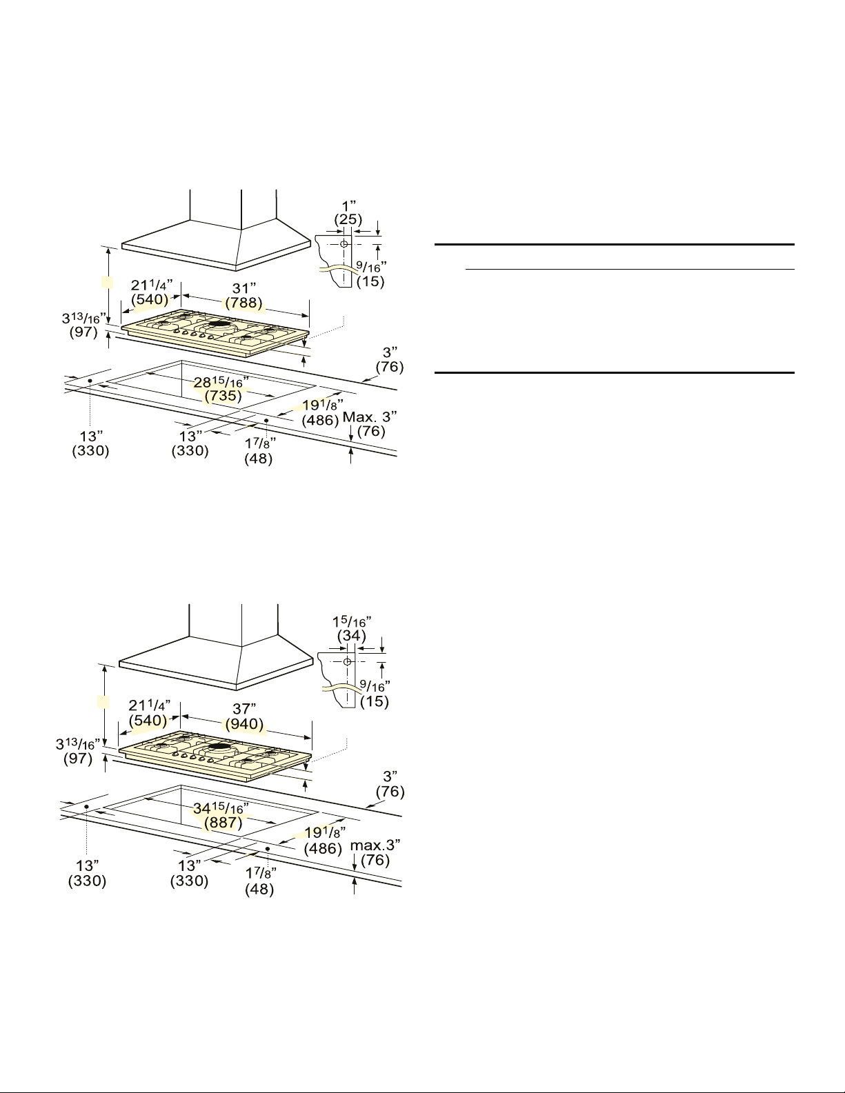
Overall Dimensions
30” Models 36” Models
Width (Side to Side) 31”
(788 mm)
Depth (Front to Back) 21 1/4”
(540 mm)
Height (Top to Bottom) 3 13/16”
(97 mm)
Note: These are overall dimensions NOT cutout dimensions.
37”
(940 mm)
21 1/4”
(540 mm)
3 13/16”
(97 mm)
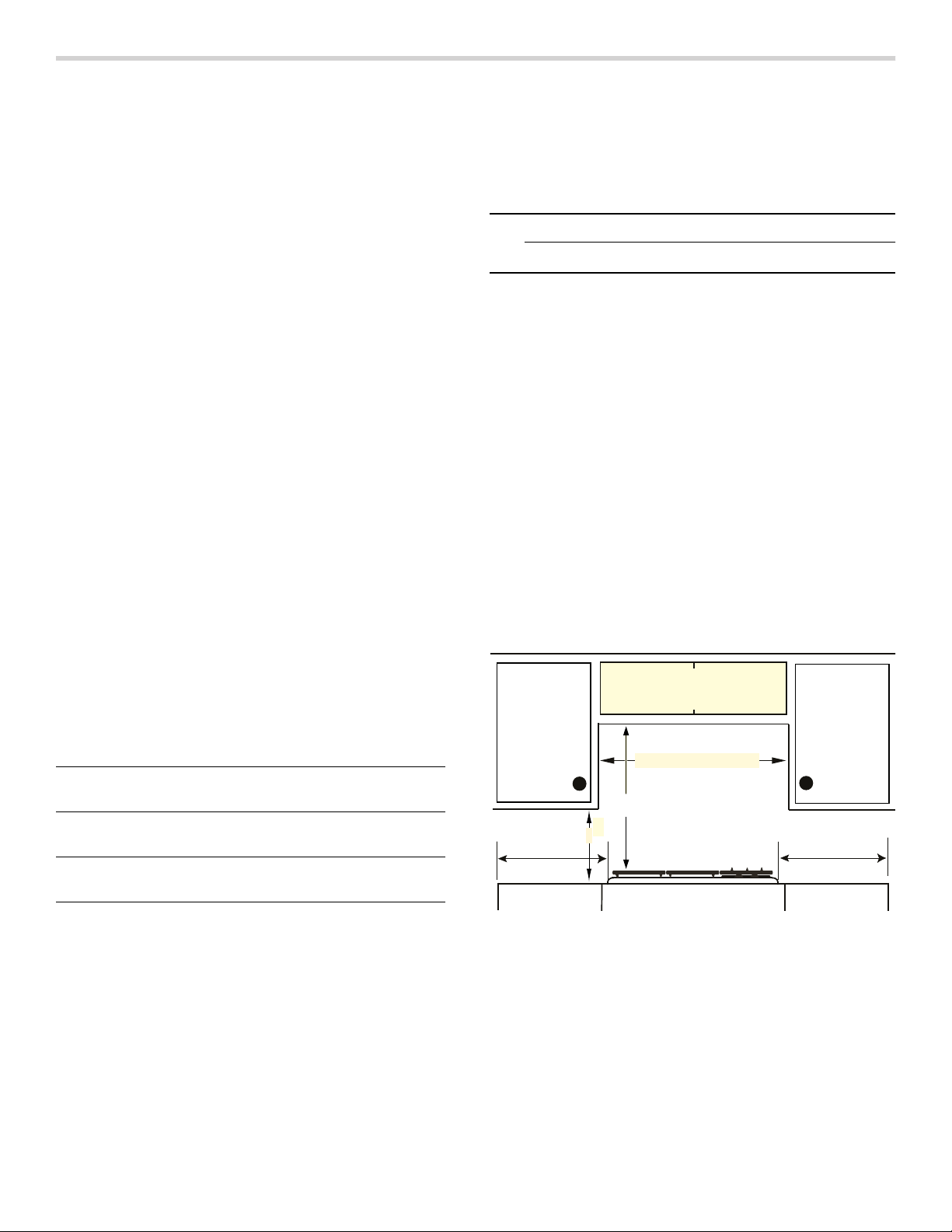
Depth from Back Wall
Cabinet 13" (330) max.
Centered over cooktop
NGM30 - min. 30" (762)
NGM36 - min. 36" (914)
Above counter - min. 30" (762)
min. 18" (458)
Left Side
min. 12" (305)
to combustible surface
Rear wall - 2" (51mm)
Right Side
min. 12" (305)
=mm
▯ Instructions are based on standard American cabinets
36” high (91cm) x 24” deep (61cm) with a 25”
(63cm) countertop.
▯ The maximum depth of a cabinet installed above the
cooktop is 13” (33cm).
Note: All measurements given must be precisely followed. If nonstandard cabinets are used, make sure they are installed with minimum dimensions shown.
Plan the installation of the unit so that the power cord,
gas shut-off valve and gas pressure regulator are
accessible from the front of the cabinet.
6
Page 7
Countertop Requirements
Mounting Requirements
Note: All measurements given must be precisely
followed. If nonstandard cabinets are used, make sure
they are installed with minimum dimensions shown in
image below.
gas
connection
*
1ʎ/ʓʘ”
(37)
*Dimension from countertop to top of grates
**When installed in combination with a hood,
refer to hood manufacturer
’s requirements for installation.
( )=mm
Use the hold down brackets supplied. See “Install the
Cooktop” section for further details.
Ventilation Requirements
We strongly recommend the installation of ventilation with the appliance. The appliance must be installed according to the furnished instructions.
9 CAUTION
The appliance should not be installed with a
ventilation system that blows air downward toward
the burners. This type of ventilation system may
cause ignition and combustion problems with the
gas cooking appliance resulting in personal injury or
unintended operation.
30” Models
*Dimension from countertop to top of grates
**When installed in combination with a hood,
refer to hood manufacturer
’s requirements for installation.
gas
connection
*
1ʎ/ʓʘ”
(37)
( )=mm
36” Models
7
Page 8
Installation Procedure
Prepare the Countertop
9 WARNING
To avoid electrical shock hazard, before installing
the cooktop, switch power off at the service panel to
prevent the power from being switched on
accidentally.
Cut out the countertop per the dimensions shown in the section “Cabinet Requirements”.
Some solid surface materials require different cutting
methods. Consult with the solid surface manufacturer for
the correct cutting method needed. Apply heat reflective
tape such as Scotch Aluminum Foil Tape #425 or #427
(not included) around the cutout so that it folds over the
top and sides. Do not wrap the tape underneath the
cooktop. Be sure the tape extends beyond the outermost
flange of the cooktop. All corners should be covered with
tape.
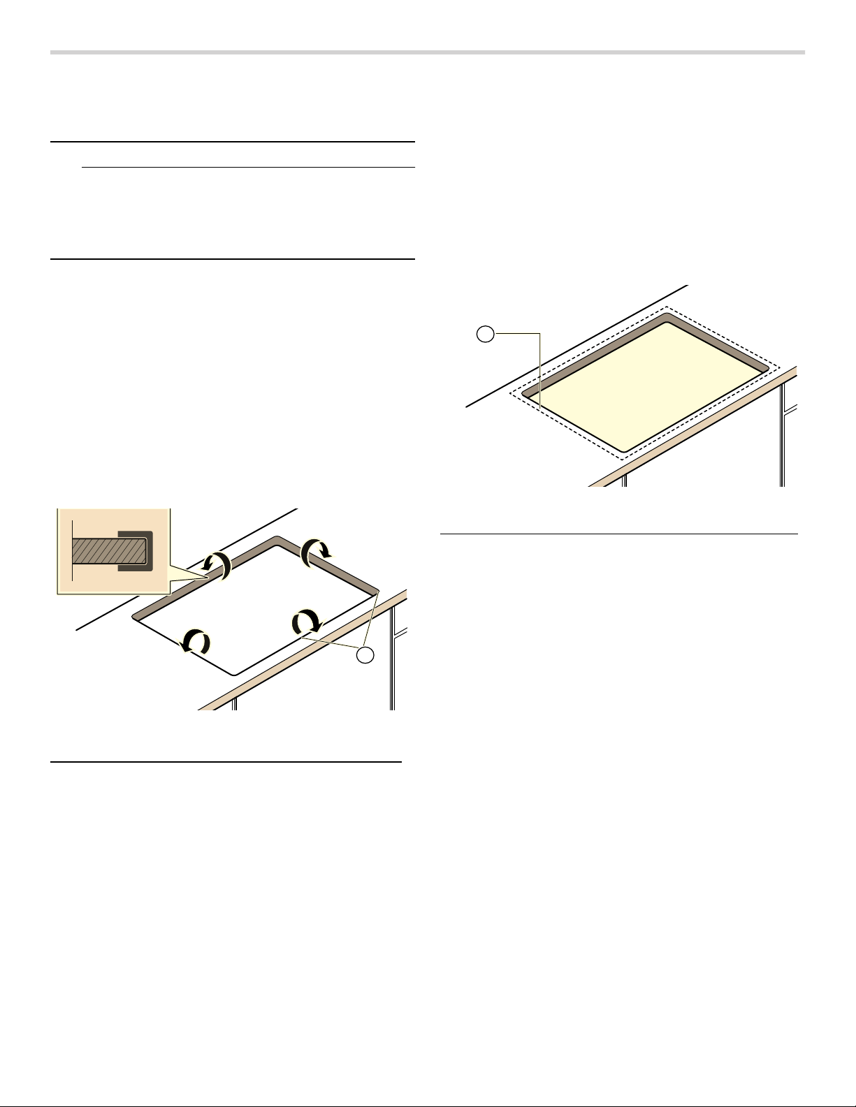
Seal the Cooktop with Foam Tape
Note: Failure to install the foam tape may affect burner
performance.
Apply the self adhesive foam tape in one continuous rectangle directly to the counter around the perimeter of the cutout as shown by the dotted line in the image below. The foam tape should be flush with the edge of the cutout.
$
Foam Tape Placement-Counter Cutout
A Foam Tape Placement
Solid Surface Countertops-Counter Cutout
A Heat Reflective Tape
$
8
Page 9
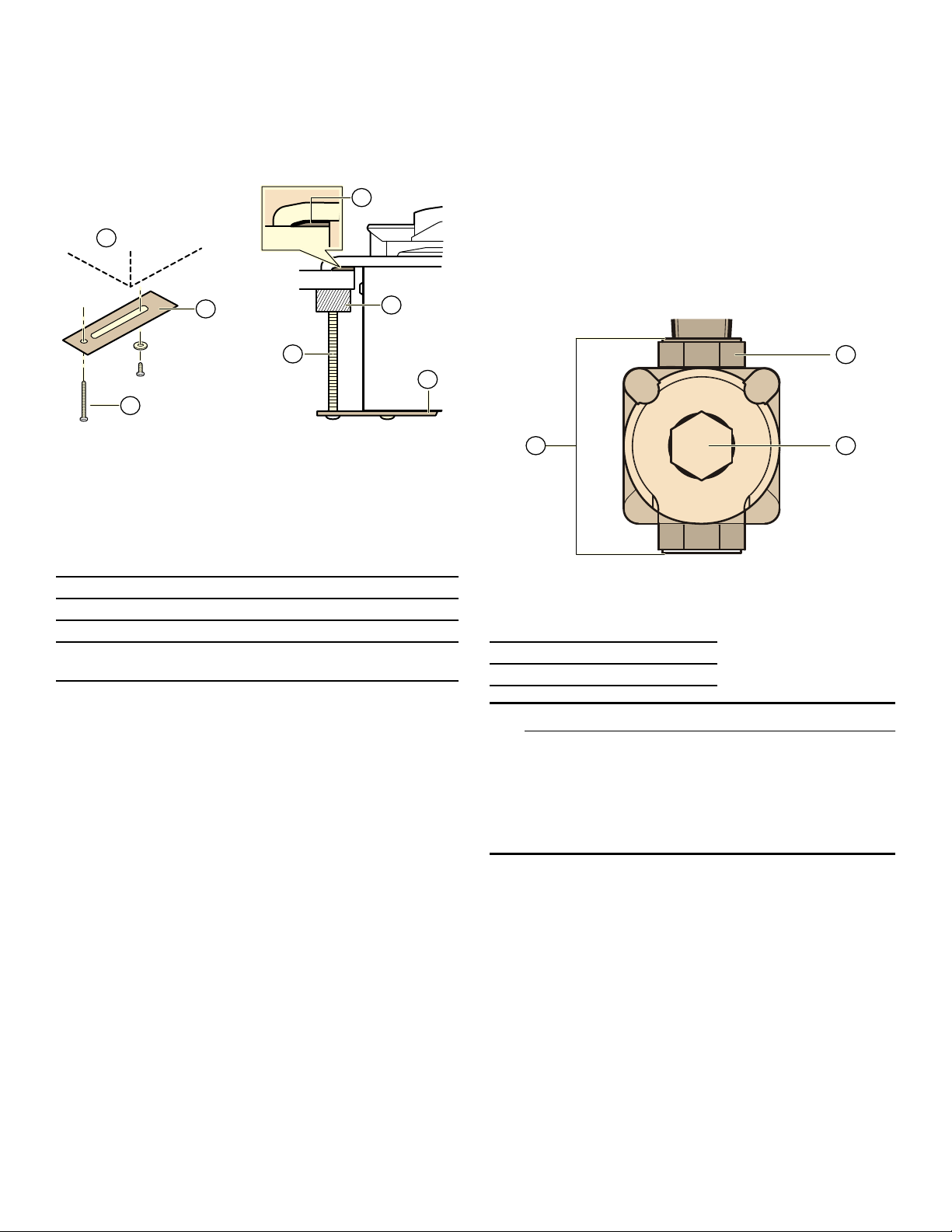
Install the Cooktop
Insert the cooktop into the cutout. Attach the clamps of the mounting brackets packaged with the cooktop. Use the washer and screws provided.
'
$
Connect Gas Supply
The gas inlet to the unit is located at the right rear of the cooktop.
Install the pressure regulator (supplied with unit) to
manifold pipe using Teflon tape on threads of manifold
pipe. Turn to hand tighten plus 1/4 turn, not exceeding 1
turn for alignment. To prevent possible damage to the
gas pressure regulator, install it after the cooktop is in its
permanent position. When the regulator is securely
installed on the manifold pipe, the conversion nut will be
easily accessible.
%
*
(
+
&
Adjust the mounting brackets to desired position and tighten screws to cooktop. Insert adjusting screw into clamp and secure cooktop to countertop.
Attaching Mounting Brackets
A Cooktop
B/H Hold Down Bracket
C/E Adjusting Screw
D Foam Tape (Seal)
G Wooden Block (to be used with solid surfacing
material)
Note: For solid surface material installations:
▯ Insert a wooden block between the end of the screw
and the bottom of the countertop.
▯ Do not overtighten adjusting screw.
▯ Trim excess aluminum tape around cooktop flange.
Tip: Install hold down bracket without the adjusting screw installed. Turn hold down brackets flush with the sides of the cutout. This will help with inserting cooktop in hard-to-reach spaces.
$
%&
Pressure Regulator
A Manifold Pipe
B Conversion Nut
C Pressure Regulator
9 WARNING
Do not attempt any adjustment of the pressure
regulator, except when converting to propane.
Adjustments could lead to leaks or cause incorrect
gas pressure to the appliance.
9
Page 10
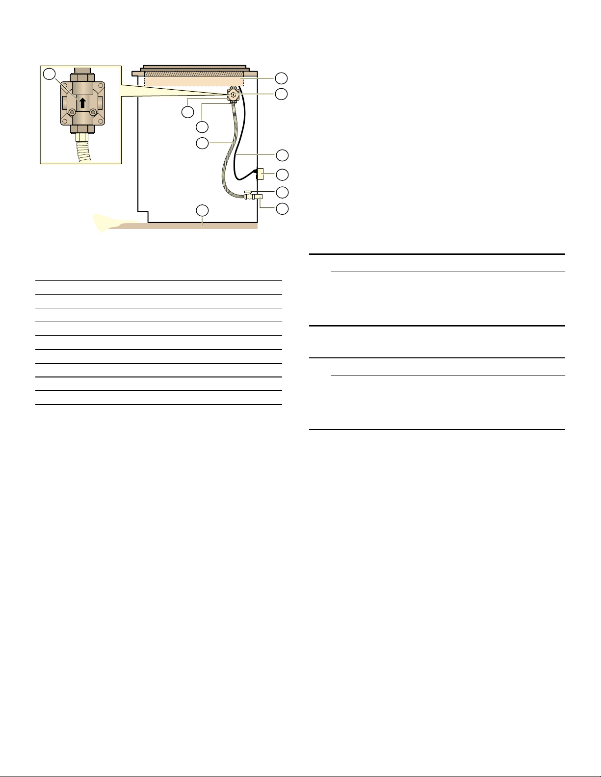
Side View Gas Cooktop Installation
Important Notes for Gas Connection:
%
$
%
&
'
(
*
Arrow on the back of
the pressure regulator
shows the direction of
gas flow.
/
+
-
.
Gas and Electrical Location
A Rough-in Cooktop Box
B Arrow on Pressure Regulator
C Pressure Regulator
D 1/2” Female Pipe Threads
E Flexible Gas Line
G Power Cord (60 inches/1,524mm)
H 120 Volt Receptacle
J Gas Cut-off Valve
K Gas Supply Line Stub-out
L Floor
Connect the gas supply line to the unit pressure regulator using a 1/2” flex gas line connector between manual shut-off valve and pressure regulator. Always use a new flex line.
Check supply line connections for leaks using a soap solution or non-corrosive leak detection fluid. Do not use a flame of any sort.
1.
Turn on gas.
2.
Apply a soap solution or non-corrosive leak detection
fluid to all joints and fittings in the gas connection
between the shut-off valve and the cooktop. Include
gas fittings and joints in the cooktop if connections
may have been disturbed during installation. Bubbles
appearing around fittings and connections indicate a
leak.
3.
If a leak appears, turn off supply line gas shut-off valve and tighten connections.
4.
Retest for leaks by turning on the supply line gas shutoff valve. When leak check is complete (no bubbles
appear), test is complete.
5.
Wipe off all soap solution or detection fluid residue.
▯ The appliance and its individual gas shutoff valve must
be disconnected from the gas supply piping system
during any pressure testing of that system at test
pressures in excess of 1/2 psi (3.5kPa).
▯ The appliance must be isolated from the gas supply
piping system by closing its individual manual shut-off
valve during any pressure testing of the gas supply
piping system at test pressures equal to or less than
1/2 psi (3.5kPa).
Connect Electrical Supply
Before connecting the 5-foot (1.5m) supply cord to a wall receptacle, make certain that gas shut-off valve and all burner controls are in OFF position.
Burner Cap and Burner Base Placement
9 WARNING
To prevent flare-ups, do not use the cooktop without
all burner caps and all burner grates properly
positioned.
9 WARNING
To prevent burns, do not touch burner caps or
grates while hot. Turn the cooktop off and allow the
burners to cool.
The burner caps must be properly placed for the cooktop to function properly. If the burner cap is not properly placed, one or more of the following problems may occur:
▯ Burner flames are too high.
▯ Flames shoot out of burners.
▯ Stainless steel discolors.
▯ Burners do not ignite.
▯ Burner flames light unevenly.
▯ Burner emits gas odor.
10
Page 11
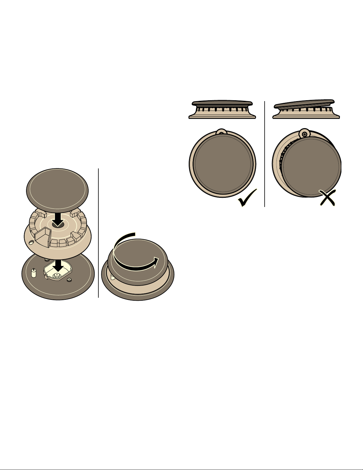
Burner Cap and Burner Base Placement
Checking Burner Cap Placement
▯ After electrical connection is complete, place each
burner base on the corresponding location on the
cooktop. One of the three bars on the burner base
should line up with the notch and prevent the base
from rotating. The small hole or cutout near the edge
should also line up with the igniter. Pay special
attention to avoid damaging the igniter during
installation of the base. See Illustration below.
▯ Once each base is located and resting evenly, place
each burner cap on its correct burner base. See
Illustration.
▯ Place burner cap gently on top of base so that the
prongs of the burner base fit snugly into the groove of
the burner cap.
▯ If the maintop is removed by a certified installer (for
example to check electrical or piping connection) the
panhead screws that were removed must be reinstalled to ensure proper functionality of burners.
1
2
▯ Check to make sure that there is no gap between the
burner cap and burner base. See illustration below for
correct and incorrect placements of the burner cap.
▯ You may gently try to move the burner cap from side
to side to check if it is properly placed. If properly
placed, the cap will click from side to side as the
prongs hit the groove ridge.
Placing Burner Caps and Bases
Checking Burner Cap Placement
11
Page 12
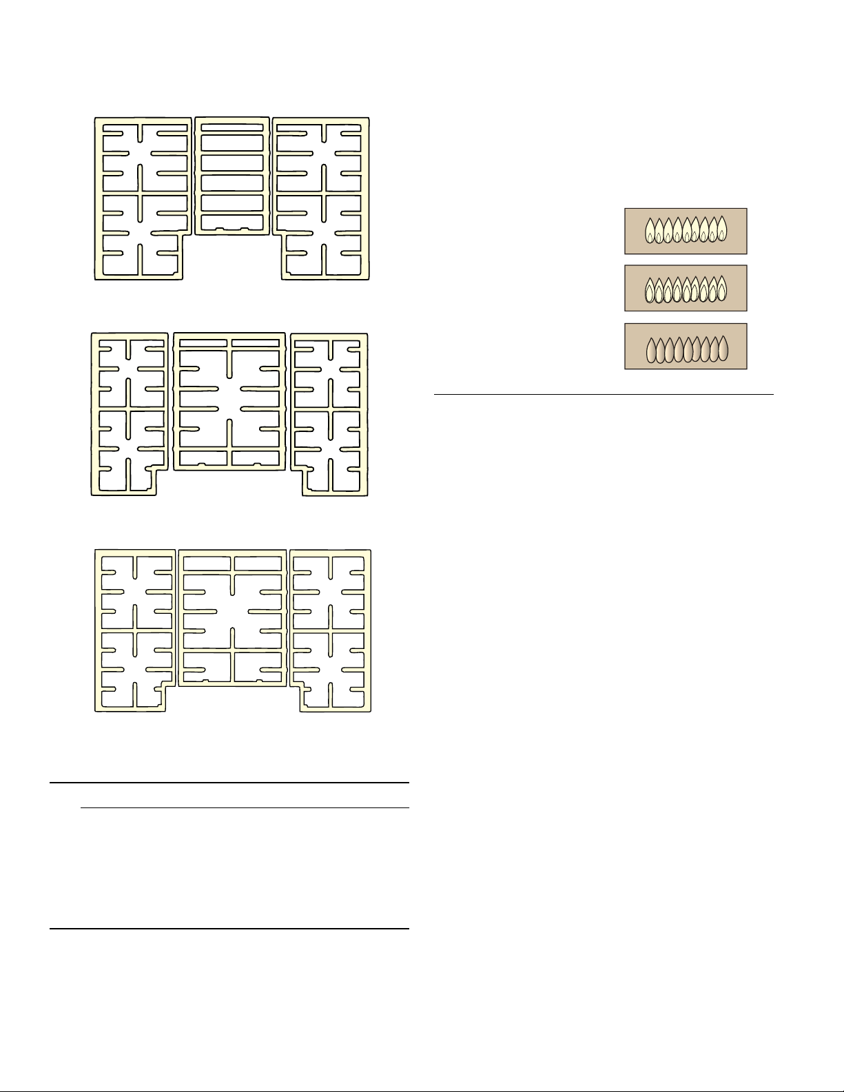
Install Burner Grates
Properly position and install each burner grate as shown in the illustration below.
30” 4 Burner
Check the Installation
Place each correct sized burner cap in its seated, notched position and check the operation of the electric igniters. Check flame characteristics. Flame should be blue with a minimal yellow tip on the outer cone of the flames.
Checking Flame Characteristics
Yellow Flames:
Further adjustment is
required.
Yellow Tips on Outer
Cones:
Normal for LP Gas
Soft Blue Flames:
Normal for Natural Gas
Note: If the flame is completely or mostly yellow, verify that the regulator is set for the correct fuel. After adjustment, retest.
30” 5 Burner
36” 5 Burner
9 WARNING
To prevent flare-ups, properly support pots and
avoid spills, all grates must be properly positioned
on the cooktop whenever the cooktop is in use.
Each of the four feet must be placed into the
corresponding dimples in the cooktop. Do not use a
grate if the rubber feet are missing or damaged.
Some yellow streaking is normal during the initial startup. Allow unit to operate 4-5 minutes and re-evaluate
before making adjustments.
For replacement of rubber feet: Call Customer Support at 1-800-944-2904.
12
Page 13

Service
Before Calling Service
If the igniters do not spark or the “on” indicator lights (available in some models) do not glow, check the power source to see if a fuse has blown or if the circuit breaker has tripped.
Refer to the Statement of Limited Warranty in the Use
and Care Manual. See the Use and Care Manual for
troubleshooting information.
Product Rating Label
The rating label shows the model number and the FD number (production number/product’s unique identifier) of your cooktop. It is located on the underside of the cooktop.
$
Rating Label Location
A Rating Label
Model number and FD Number
The model number and the FD number of your appliance are found on the rating label. Make a note of these numbers in the space below to save time in the event your appliance requires service.
Model # FD #
Bosch Customer Support 800-944-2904
Keep your invoice or escrow papers for warranty
validation if service is needed.
13
Page 14

Table des Matières
Notice d’utilisation
Définitions de sécurité ................................................ 14
IMPORTANTES CONSIGNES DE SÉCURITÉ ............. 15
Utilisation sécuritaire de l'électroménager
alimenté au gaz : ............................................................... 15
Installation au gaz propane ............................................. 16
Exigences en matière de sécurité pour l'utilisation et
l'équipement ....................................................................... 16
Sécurité de manutention des appareils ........................ 17
Codes et normes de sécurité ......................................... 17
Avertissement issue de la proposition 65
de l’État de la Californie : ................................................ 17
Sécurité électrique ............................................................ 17
Installation à altitude élevée ............................................ 17
Avant de commencer .................................................. 18
Outils et pièces nécessaires ........................................... 18
Pièces incluses .................................................................. 18
Informations générales ..................................................... 18
&HWDSSDUHLOpOHFWURPpQDJHU%RVFKHVWIDEULTXpSDU
%6++RPH$SSOLDQFHV&RUSRUDWLRQ
0DLQ6WUHHW6XLWH
,UYLQH&$
Préparatifs .......................................................................... 18
Procédure d'installation ............................................. 20
Préparation du plan de travail ........................................ 20
Sceller la table de cuisson avec le ruban de
mousse ............................................................................... 20
Installation de la table de cuisson ................................. 21
Branchement du gaz ........................................................ 21
Brancher l'alimentation électrique .................................. 22
Positionnement du chapeau et de la base
du brûleur ........................................................................... 22
Installation des grilles du brûleur ................................... 24
Vérification de l'installation .............................................. 24
Dépannage ................................................................... 25
Avant d'appeler le service de dépannage ................... 25
9RXVDYH]GHVTXHVWLRQV"
ZZZERVFKKRPHFRPXV
1RXVQRXVIHURQVXQSODLVLUGHYRXVVHUYLU
Définitions de sécurité
9 AVERTISSEMENT
Ceci indique que le non-respect de cet
avertissement peut entraîner des blessures graves,
voire la mort.
9 ATTENTION
Ceci indique que le non-respect de cet
avertissement peut entraîner des blessures légères
ou de gravité moyenne.
ââ
AVIS : Ceci indique que la non-conformité à cet avis de sécurité peut entraîner des dégâts matériels ou endommager l'appareil.
Remarque : Ceci vous signale des informations et/ou indications importantes.
14
Page 15

9 IMPORTANTES CONSIGNES DE SÉCURITÉ
LIRE ET CONSERVER CES INSTRUCTIONS
IMPORTANTES CONSI GNES DE SÉCURI TÉLI RE ET CONS ER VE R CES INSTRUCTIONS
Utilisation sécuritaire de l'électroménager alimenté au gaz :
$9(57,66(0(176LOHVGLUHFWLYHVQHVRQWSDV
VXLYLHVjODOHWWUHLO\DXQULVTXHGLQFHQGLHRX
GH[SORVLRQSRXYDQWHQWUDvQHUGHVGRPPDJHV
PDWpULDX[GHVEOHVVXUHVRXXQGpFqV
²
1HSDVFRQVHUYHURXXWLOLVHUGHOHVVHQFHRX
GDXWUHVOLTXLGHVRXYDSHXUVLQIODPPDEOHVj
SUR[LPLWpGHFHWDSSDUHLORXGHWRXWDXWUHDSSDUHLO
²
48()$,5(6,92863(5&(9(=81(2'(85'(*$=
1HSDVHVVD\HUGHPHWWUHXQDSSDUHLOVRXVWHQVLRQ
1HSDVWRXFKHUGLQWHUUXSWHXUGHFRXUDQWpOHFWULTXH
1HSDVXWLOLVHUGHWpOpSKRQHVGDQVOpGLILFH
&RPPXQLTXHULPPpGLDWHPHQWDYHFOHIRXUQLVVHXU
GHJD]GHSXLVODSSDUHLOWpOpSKRQLTXHGXQYRLVLQ
5HVSHFWHUOHVGLUHFWLYHVGXIRXUQLVVHXUGHJD]
6LOVDYqUHLPSRVVLEOHGHMRLQGUHOHIRXUQLVVHXUGH
JD]FRPPXQLTXHUDYHFOHVSRPSLHUV
8WLOLVHUOHVVHUYLFHVGXQLQVWDOODWHXURXGXQHDJHQFH
²
GHVHUYLFHVTXDOLILpVRXOHIRXUQLVVHXUGHJD]SRXU
SURFpGHUjOLQVWDOODWLRQHWDX[UpSDUDWLRQV
15
Page 16

9 IMPORTANTES CONSIGNES DE SÉCURITÉ
LIRE ET CONSERVER CES INSTRUCTIONS
IMPORTANT : CONSERVEZ CES CONSIGNES À L'INTENTION DE L'INSPECTEUR EN ÉLECTRICITÉ.
INSTALLATEUR : PRIÈRE DE LAISSER CES CONSIGNES AVEC CET APPAREIL À L'INTENTION DU PROPRIÉTAIRE.
PROPRIÉTAIRE : PRIÈRE DE CONSERVER CES CONSIGNES POUR RÉFÉRENCE ULTÉRIEURE.
AVERTISSEMENT
Correctement entretenu, votre électroménager neuf a été
conçu pour être sécuritaire et fiable. Lisez attentivement
toutes les instructions avant l’utilisation. Ces précautions
réduiront le risque de brûlure, d'électrocution, d’incendie
et de blessures corporelles. Lorsque vous utilisez des
appareils électroménagers de cuisine, il importe de
suivre des précautions de sécurité de base, y compris
celles indiquées dans les pages suivantes.
AVERTISSEMENT
Ne pas réparer, remplacer ni retirer toute pièce de
l’électroménager à moins que cela ne soit
spécifiquement recommandé par les manuels.
L'installation, l'entretien ou une réparation inadéquat
pourrait causer des blessures ou des dégâts matériels.
Consulter ce manuel pour les directives d'utilisation.
Toute autre réparation doit être effectuée par une agence
de service d'entretien autorisé.
▯ Installer un robinet d'arrêt près de l'électroménager. Il
doit être facilement accessible en cas d'urgence.
▯ L'installateur doit procéder au test de fuites selon les
consignes fournies dans le présent manuel.
▯ L'appareil et son propre robinet d'arrêt doivent être
déconnectés de la canalisation du système
d'alimentation en gaz au cours de test aux pressions
qui dépassent 1/2 PSI (3,5 kPa).
▯ L’électroménager doit être isolé de la canalisation du
système d'alimentation en gaz en fermant son propre
robinet d'arrêt manuel pour tout test de pression à des
pressions égales ou inférieures à 1/2 PSI (3,5 kPa).
▯ La pression d'admission minimum doit être de 1 po de
colonne d'eau au-dessus de la pression d'admission
imprimée sur la plaque signalétique.
▯ La pression d'admission maximum ne doit pas
excéder 14 po de colonne d'eau (34,5 millibars).
▯ Pour les installations au Massachusetts :
▯ L'installation doit être exécutée par un entrepreneur,
un plombier ou un ajusteur d'appareils à gaz
qualifié ou autorisé par l'État, la province ou la
région d'installation de cet électroménager.
▯ Le robinet d'arrêt doit être robinet à gaz avec
poignée en T.
▯ Le connecteur à gaz souple doit être neuf et ne doit
pas dépasser 36 pouces.
▯ Installateur : prière d'indiquer au propriétaire,
l'emplacement du robinet d'arrêt.
Installation au gaz propane
▯ Le réservoir de gaz propane doit être doté de son
propre régulateur de pression élevée. De plus, le
régulateur de pression livré avec cet appareil doit
aussi être utilisé.
▯ L'électroménager est livré de l'usine prêt à utiliser avec
du gaz naturel. Il doit être converti pour usage avec
gaz propane. Un technicien ou un installateur qualifié
doit procéder à la conversion.
Exigences en matière de sécurité pour l'utilisation et l'équipement
▯ Utiliser un système de ventilation convenable avec la
table de cuisson.
▯ Retirer tout le ruban adhésif et l'emballage avant
d'utiliser l'électroménager. Jeter l'emballage après
avoir déballé l'électroménager. Ne jamais laisser les
enfants jouer avec le matériel d'emballage.
▯ Ne jamais altérer ni modifier la configuration de
l'électroménager. Par exemple, ne pas retirer les
panneaux, les couvre-fils ou les vis.
▯ Pour éliminer le risque de brûlure ou d'incendie
lorsque vous vous étirez au-dessus des surfaces
chauffantes de l'électroménager, il faut éviter d'installer
des armoires de rangement au-dessus de la surface
de l'électroménager. Si une armoire de rangement est
installé, il est possible de réduire le risque en installant
une hotte qui dépasse (horizontalement) d'au moins
5 po le bord du fond de l'armoire.
▯ Vérifier que la profondeur des armoires au-dessus de
la table de cuisson est au maximum de 13 po
(330 m).
16
Page 17

9 IMPORTANTES CONSIGNES DE SÉCURITÉ
LIRE ET CONSERVER CES INSTRUCTIONS
Sécurité de manutention des appareils
ATTENTION
▯ L’appareil est lourd et son déplacement exige
au moins deux personnes ou encore un
équipement approprié.
▯ Les surfaces cachées peuvent comporter des
arêtes vives. Redoubler de vigilance quand
vous passez la main derrière ou sous l'appareil
électroménager.
Codes et normes de sécurité
▯ Cet appareil est conforme à une ou plusieurs des
normes suivantes :
ANSI Z21.1, Appareils électroménagers pour la
cuisson à gaz
▯ Il incombe au propriétaire et à l'installateur de
déterminer si des exigences et/ou normes
additionnelles s'appliquent pour des installations
spécifiques.
▯ L’installation doit être conforme aux codes locaux ou,
en l’absence de tels codes, au National Fuel Gas
Code ANSI Z223.1/NFPA 54 ou, au Canada, au code
national CSA B149.1 d’installation du gaz naturel et
du propane.
▯ L'électroménager doit être mis à la terre en conformité
aux codes locaux, ou en l’absence de tels codes, au
National Electric Code ANSI/NFPA 70 ou, au Canada,
au code canadien de l’électricité CSA C22.1-02.
Avertissement issue de la proposition 65 de l’État de la Californie :
AVERTISSEMENT
Ce produit peut vous exposer à des produits chimiques,
comme du chlorure de vinyle, reconnus par l’État de la
Californie comme causant le cancer, des malformations
congénitales ou d’autres effets nocifs sur la
reproduction. Pour de plus amples renseignements,
consultez www.P65Warnings.ca.gov.
Remarque : AVIS DE SÉCURITÉ IMPORTANT : En application de la loi californienne concernant la salubrité de l’eau et la protection contre les substances chimiques (« California Safe Drinking Water and Toxic Enforcement Act »), le gouverneur de Californie est tenu de publier une liste reconnue par l’État de Californie comme étant cancérigènes ou pouvant causer des malformations ou présenter un danger pour la reproduction, et les entreprises sont tenues d’avertir les consommateurs des risques potentiels d’exposition à de telles substances. La combustion de gaz combustible pour la cuisson et l'élimination de résidus pendant l'autonettoyage peuvent générer de faibles quantités de monoxyde de carbone. Dans les fours équipés du Nettoyage Auto, de faibles quantités de formaldéhyde peuvent se dégager lors de l'élimination des salissures pendant les quelques premiers cycles autonettoyants. La Californie classe le formaldéhyde parmi les produits potentiellement cancérigènes. Le monoxyde de carbone est une cause possible de toxicité pour la reproduction. Il est possible de réduire l'exposition à ces substances en :
1.
assurant une bonne ventilation lors de la cuisson au gaz; et
2.
utilisant l'appareil selon les instructions de ce manuel.
Sécurité électrique
▯ Avant de brancher le cordon électrique, vérifier que
toutes les commandes sont à la position OFF (Arrêt).
▯ Pour les électroménagers dotés d'un cordon
d'alimentation avec fiche, ne pas couper ni enlever la
broche de mise à la terre. Pour éviter toute
électrocution, brancher le cordon dans une prise de
courant correspondante avec mise à la terre. En cas
de doute concernant la mise à la terre appropriée de
la prise murale, le client doit faire vérifier celle-ci par
un électricien qualifié.
▯ Cet électroménager doit être installé conformément au
Code national de l'électricité ou au Code canadien de
l'électricité. L'installation de la table de cuisson doit
être sur un circuit mis à la terre sans disjoncteur
différentiel de fuite à la terre (non-DDFT).
▯ Installateur : Indiquez au propriétaire l'emplacement
du disjoncteur ou du fusible. Identifiez sa position pour
pouvoir le retrouver facilement.
▯ Avant l'installation, couper l'alimentation au panneau
de service. Verrouiller le panneau de service pour
empêcher que l'alimentation ne soit rétablie par
accident.
▯ S'assurer que l’électroménager est correctement
installé et mis à la terre par un technicien qualifié.
L’installation, les raccordements électriques et la mise
à la terre doivent être conformes avec tous les codes
applicables.
Installation à altitude élevée
Communiquer avec le service après-vente pour une
utilisation au-dessus de 2 000 pi (610 mètres).
17
Page 18

Avant de commencer
Outils et pièces nécessaires
▯ Tournevis à tête Phillips
▯ Tournevis à lame plate de précision
▯ Ruban à mesurer
▯ Ruban de teflon (de classe Gaz)
▯ Clé réglage ou pince multiprise
Pièces incluses
▯ Ruban de mousse
▯ Supports de fixation (4)
▯ Vis, no 10-32 x 2 1/2 po (63,8 mm) (4)
▯ Vis à tôle, No 8 x 3/8 po (9,5 mm) (4)
▯ Rondelles (4)
▯ Grilles de brûleur (3)
▯ Brûleurs
▯ Modèles de 30 po : (4) ou (5)
▯ Modèles de 36 po : (5)
▯ Chapeaux de brûleur
▯ Modèles de 30 po : (4) ou (5)
▯ Modèles de 36 po : (5)
▯ Régulateur de pression
▯ Trousse de conversion au gaz de PL
Remarque : Si des pièces sont manquantes ou endommagées, composer le numéro indiqué ou écrire à l'adresse indiquée à la troisième de couverture.
Préparatifs
Exigences électriques
9 ATTENTION
Ne pas utiliser une rallonge avec la table de
cuisson.
Cet électroménager a besoin d'un raccord de 60 Hz,
15 A, 120 volts c.a. Planifier l'installation de sorte que le
raccord électrique est accessible de l'avant de l'armoire.
Exigences en matière de gaz
Pression d'admission :
▯ Gaz naturel : 7 po de colonne d'eau (14,9 millibars)
▯ Gaz propane : 11 po de colonne d'eau
(27,4 millibars)
Le réservoir de gaz propane doit être doté de son propre
régulateur de pression élevée en plus du régulateur de
pression fourni avec cet appareil. Cette table de cuisson
est livrée de l'usine prête à utiliser avec du gaz naturel.
Pour une conversion au gaz de PL, un technicien ou un
installateur qualifié doit y procéder.
Informations générales
Dimension hors tout
Modèles de
30 po
Largeur (d'un côté à
l'autre)
Profondeur (de l'avant
vers l'arrière)
Hauteur (du haut au
bas)
31 po
(788 mm)
21 1/4 po
(540 mm)
3 13/16 po
(97 mm)
Remarque : Ce sont les dimensions hors tout et NON les dimensions pour la découpe.
Modèles de
36 po
37 po
(940 mm)
21 1/4 po
(540 mm)
3 13/16 po
(97 mm)
18
Page 19

Exigences concernant les armoires
Profondeur depuis la paroi arrière
Armoire 13 po (330) max.
Centrée au-dessus
de la table de cuisson
NGM30 : min. 30 po (762)
NGM36 : min. 36 po (914)
Au-dessus du comptoir :
min. 30 po (762)
min. 18 po (458)
Côté gauche
min. 12 po (305)
de la surface inflammable
Paroi arrière : 2 po (51 mm)
Côté droit
min. 12 po (305)
( )=mm
▯ Les consignes sont fondées sur des armoires
normales (aux États-Unis) de 36 po (91 cm) de
hauteur et de 24 po (61 cm) de profondeur avec un
plan de travail à 25 po (63 cm).
▯ La profondeur maximale de l'armoire installée au-
dessus de la table de cuisson est de 13 po (33 cm).
Remarque : Il faut respecter précisément toutes les mesures fournies. Dans le cas d'armoires hors normes, s'assurer qu'elles ont les dimensions minimales d'installation indiquées.
* Distance du plan de travail à la face supérieur des grilles
** Lors d'une installation en combinaison avec une hotte, consulter
les exigences d'installation du fabricant de la hotte.
Modèles de 30 po
connexion
au gaz
*
1ʎ/ʓʘ
(37)
( )=mm
Planifier l'installation de l'appareil de sorte que le cordon
d'alimentation, le robinet d'arrêt et le régulateur de
pression du gaz sont accessibles de l'avant de l'armoire.
Exigences concernant le plan de travail
Remarque : Il faut respecter précisément toutes les
mesures fournies. Dans le cas d'armoires hors normes,
s'assurer qu'elles ont les dimensions minimales
d'installation indiquées sur l'image ci-dessous.
*
1ʎ/ʓʘ
(37)
* Distance du plan de travail à la face supérieur des grilles
** Lors d'une installation en combinaison avec une hotte, consulter
les exigences d'installation du fabricant de la hotte.
Modèles de 36 po
connexion
au gaz
( )=mm
19
Page 20

Exigences pour la fixation
Utiliser les supports de fixation fournis. Consulter la
section « Installation de la table de cuisson » pour de
plus amples renseignements.
Exigences concernant la ventilation
Nous recommandons fortement l'installation d'un système de ventilation avec l'électroménager. Il doit être installé conformément aux consignes d'installation fournies.
Procédure d'installation
Préparation du plan de travail
9 AVERTISSEMENT
Pour éviter tout danger d'électrocution avant
d'installer la table de cuisson, couper l'alimentation
au panneau de service pour éviter que l'alimentation
soit rétablie accidentellement.
Découper le plan de travail aux dimensions indiquées dans la section « Exigences concernant les armoires ».
9 ATTENTION
L'électroménager ne doit pas être installé avec un
système de ventilation qui souffle l'air vers le bas en
direction des brûleurs. Ce type de système de
ventilation peut entraîner des problèmes d'allumage
et de combustion avec l'appareil de cuisson au gaz
pouvant causer des blessures corporelles ou un
fonctionnement indésirable.
Sceller la table de cuisson avec le ruban de mousse
Remarque : Ne pas installer le ruban de mousse peut
influencer le rendement du brûleur.
Appliquer le ruban autocollant de mousse en un
rectangle ininterrompu sur le rebord de la découpe dans
le plan de travail (sur le périmètre) comme illustré par la
ligne pointillée sur l'image ci-dessous. Le ruban de
mousse doit être de niveau avec le rebord de la
découpe.
Certains matériaux demandent des méthodes de
découpe différentes. Consulter le fabricant de la surface
solide pour connaître la bonne méthode de découpe.
Appliquer du ruban réflecteur de chaleur comme du
ruban d'aluminium Scotch no 425 ou no 427 (non
compris) autour de la découpe pour qu'il se plie par
dessus la surface et les côtés. Ne pas plier le ruban sous
la table de cuisson. S'assurer que le ruban dépasse audelà du rebord externe de la collerette de la table de
cuisson. Tous les coins doivent être couverts de ruban.
$
Découpe de la surface solide du plan de travail
A Ruban réflecteur de chaleur
$
Placement du ruban de mousse sur le périmètre de la
découpe dans le plan de travail
A Placement du ruban de mousse
20
Page 21

Installation de la table de cuisson
Insérer la table de cuisson dans la découpe. Fixer les pinces du support de fixation livré avec la table de cuisson. Utiliser la rondelle et les vis fournis.
'
$
%
(
&
Régler le support de fixation à la hauteur désirée, et serrer les vis à la table de cuisson. Insérer les vis de réglage dans la pince et fixer solidement la table de cuisson au plan de travail.
*
+
Branchement du gaz
L'admission de gaz de l'appareil est située à droite, à l'arrière de la table de cuisson.
Installer le régulateur de pression (fourni avec cet
appareil) au tuyau collecteur avec du ruban teflon sur les
filets du tuyau collecteur. Serrer à la main puis tourner 1/
4 de tour de plus sans excéder 1 tour, pour l'alignement.
Pour éviter d'endommager le régulateur de pression de
gaz, l'installer après avoir mis la table de cuisson dans
sa position permanente. Une fois le régulateur
solidement installé sur le tuyau collecteur, il sera facile
d'accéder à l'écrou de conversion.
$
%&
Fixation des supports
A Table de cuisson
B/H Support de retenue
C/E Vis de réglage
D Ruban de mousse (scellé)
G Bloc de bois (à utiliser avec le matériau de la
surface solide)
Remarque : Installation sur une surface solide :
▯ Insérer un bloc de bois entre l'extrémité de la vis et le
dessous du plan de travail.
▯ Ne pas trop serrer la vis de réglage.
▯ Couper l'excès de ruban d'aluminium autour de la
collerette de la table de cuisson.
Conseil : Installer le support de retenue sans la vis de réglage. Tourner le support de retenue pour qu'il soit de niveau avec les côtés de la découpe. Cela aidera à la pose de la table des cuisson dans des espaces difficiles à atteindre.
Régulateur de pression
A Tuyau collecteur
B Écrou de conversion
C Régulateur de pression
9 AVERTISSEMENT
Ne pas essayer d'ajuster le régulateur de pression à
moins de convertir l'appareil électroménager au
propane. Les réglages peuvent entraîner des fuites
ou une mauvaise pression en direction de l'appareil
électroménager.
21
Page 22

Vue latérale de l'installation de la table de cuisson au gaz
%
$
%
&
'
(
*
La flèche au dos du
régulateur de pression
pointe dans la direction
du débit de gaz.
/
+
-
.
Emplacement du gaz et de l'électricité
A Boîtier de la robinetterie brute de la table de
cuisson
B Flèche sur le régulateur de pression
C Régulateur de pression
D Tuyau de 1/2 po à filets femelles
E Conduite de gaz souple
G Cordon d'alimentation (60 po/1 524 mm)
H Prise de 120 volts
J Robinet d'arrêt du gaz
K Embout pour la conduite d'alimentation en gaz
L Plancher
Raccorder la conduite d'alimentation en gaz au régulateur de pression de l'appareil avec un connecteur souple de gaz de 1/2 po entre le robinet d'arrêt manuel et le régulateur de pression. Toujours utiliser une conduite souple neuve.
Vérifier la présence de fuites des conduites d'alimentation au moyen d'une solution savonneuse ou d’un liquide de détection de fuites non corrosif. Ne jamais utiliser une flamme sans égard au type de flamme.
4.
Tester de nouveau la présence de fuites en ouvrant le robinet d'arrêt de l'alimentation de gaz. Quand aucune bulle n'apparaît, le test de fuite est terminé.
5.
Essuyer tout résidu de la solution savonneuse ou du liquide de détection de fuite.
Remarques importantes pour les raccords de gaz :
▯ L'appareil et son propre robinet d'arrêt doivent être
déconnectés de la canalisation du système
d'alimentation en gaz au cours de tests de pression de
ce système aux pressions qui dépassent 1/2 PSI
(3,5 kPa).
▯ L’appareil électroménager doit être isolé de la
canalisation du système d'alimentation en gaz en
fermant son propre robinet d'arrêt manuel pour tout
test de pression de la canalisation du système
d'alimentation en gaz à des pressions égales ou
inférieures à 1/2 PSI (3,5 kPa).
Brancher l'alimentation électrique
Avant de raccorder le cordon d'alimentation de 5 pi (1,5 m) à une prise murale, s'assurer que le robinet d'arrêt et toutes les commandes de brûleur sont en position fermée.
Positionnement du chapeau et de la base du brûleur
9 AVERTISSEMENT
Pour éviter des flambées, ne pas utiliser la table de
cuisson sans tous les chapeaux de brûleurs en
place et toutes les grilles de brûleur bien
positionnées.
9 AVERTISSEMENT
Pour éviter les brûlures, ne pas retirer les chapeaux
de brûleur ni les grilles quand ils sont chauds.
Éteindre la table de cuisson et laisser les brûleurs
refroidir.
1.
Ouvrir le gaz.
2.
Appliquer une solution savonneuse ou un liquide de
détection de fuites non corrosif à toutes les jonctions
et tous les raccords des conduites de gaz entre le
robinet d'arrêt et la table de cuisson. Inclure les
raccords et les jonctions de gaz de la table de cuisson
si les raccords auraient pu être déréglés au cours de
l'installation. Une bulle qui apparaît autour d'un
raccordement indique une fuite.
3.
En présence d'une fuite, couper l'alimentation en gaz en fermant le robinet d'arrêt et serrer le ou les raccords qui fuient.
22
Il faut que les chapeaux de brûleurs soient correctement positionnés pour le bon fonctionnement de la table de cuisson. Un ou plusieurs problèmes peuvent survenir si un chapeau de brûleur n’est pas bien positionné :
▯ La flamme du brûleur est trop élevée.
▯ Des flammes jaillissent des brûleurs.
▯ L’acier inoxydable se décolore.
▯ Les brûleurs ne s’allument pas.
▯ La flamme du brûleur n’est pas uniforme.
▯ Une odeur de gaz se dégage du brûleur.
Page 23

Positionnement du chapeau et de la base du brûleur
Vérification du positionnement du chapeau du brûleur
▯ Après avoir terminé le raccordement électrique,
déposer chaque base de brûleur à l’endroit
correspondant sur la table de cuisson. Une des trois
rainures sur la base du brûleur doit être alignée avec
l'encoche pour empêcher son pivotement. Le petit trou
ou la petite découpe près du rebord doit aussi être
aligné(e) avec l’allumeur. Faire très attention de ne
pas endommager l’allumeur lors de l’installation de la
base. Voir l’illustration ci-dessous.
▯ Une fois toutes les bases installées et bien appuyées,
placer les chapeaux de brûleur sur la bonne base.
Voir l’illustration.
▯ Déposer délicatement le chapeau de brûleur sur le
dessus de la base de sorte que les pattes de la base
soient bien ajustées dans la goulotte du chapeau du
brûleur.
▯ Si un installateur certifié retire la table de travail (par
exemple pour vérifier le raccordement électriques ou
des conduites), il faut réinstaller les vis à tête
cylindrique pour assurer le bon fonctionnement des
brûleurs.
1
2
▯ S’assurer qu’il n’y a aucun espace entre le chapeau et
la base du brûleur. Consulter l’illustration ci-dessous
pour voir un positionnement correct et incorrect du
chapeau du brûleur.
▯ Vous pouvez essayer délicatement de bouger le
chapeau du brûleur pour vérifier s’il est correctement
positionné. Si tel est le cas, un clic se fera entendre
lorsque les pattes du chapeau frapperont la saillie de
la goulotte.
Positionnement des chapeaux et des bases de brûleur
Vérification du positionnement du chapeau du brûleur
23
Page 24

Installation des grilles du brûleur
Positionner et installer correctement la grille de chaque brûleur comme illustré ci-dessous.
Modèle de 30 po à 4 brûleurs
Vérification de l'installation
Insérer chaque chapeau de brûleur du bon diamètre en
place sur la rainure et vérifier le fonctionnement des
allumeurs électriques. Vérifier les caractéristiques de la
flamme. La flamme doit être bleue avec une toute petite
extrémité jaune sur le cône extérieur des flammes.
Vérification des caractéristiques de la flamme
Flammes jaunes :
Réglages supplémentaires requis.
Extrémités des cônes
externes jaunes :
Normales pour un gaz de
pétrole liquéfié
Flammes bleues
douces :
Normales pour le gaz
naturel
Remarque : Si la flamme est entièrement ou presque toute jaune, vérifier si le régulateur est réglé au bon combustible. Après le réglage, procéder à un nouveau test.
Modèle de 30 po à 5 brûleurs
Modèle de 36 po à 5 brûleurs
9 AVERTISSEMENT
Pour éviter des flambées, toutes les grilles doivent
être bien positionnées sur la table de cuisson à
chaque utilisation pour bien soutenir les casseroles
et éviter les éclaboussures. Chacun des quatre
pieds doit s’appuyer dans les petites dépressions
correspondantes de la table de cuisson. Ne pas
utiliser une grille si les pieds de caoutchouc sont
manquants ou endommagés.
Au cours du démarrage initial, il est normal que la
flamme soit bigarrée de jaune. Laisser l'appareil
fonctionner de quatre à cinq minutes puis réévaluer
avant de procéder aux réglages.
Pour remplacer les pieds de caoutchouc :
Communiquer avec le Service après-vente au 1-800-944-
2904.
24
Page 25

Dépannage
Avant d'appeler le service de dépannage
Si les allumeurs ne produisent pas d'étincelles ou que les témoins ne s'allument pas (offerts sur certains modèles), vérifier la source d'alimentation électrique à la recherche d'un fusible grillé ou d'un disjoncteur actionné.
Consultez l'énoncé de garantie limitée dans le Manuel
d'utilisation et d'entretien. Consultez le Manuel
d'utilisation et d'entretien pour les renseignements de
dépannage.
Plaque signalétique du produit
La plaque signalétique comporte le numéro de modèle et le numéro FD (numéro de production/code unique d'identification) de la table de cuisson. Elle est située sur le dessous de la table de cuisson.
$
Emplacement de la plaque signalétique
A Plaque signalétique
Numéro de modèle et numéro FD
Le numéro de modèle et le numéro FD de l'électroménager figurent sur la plaque signalétique. Prendre ces numéros en note dans l'espace ci-dessous pour sauver du temps, au cas où l'électroménager aurait besoin d'être réparé.
No de modèle No FD
Service après-vente de
Bosch
Conservez votre facture ou votre contrat aux fins de
validation de garantie si jamais vous avez besoin d'une
réparation.
800-944-2904
25
Page 26

Contenido
Manual de instrucciones
Definiciones de seguridad .......................................... 26
INSTRUCCIONES DE SEGURIDAD IMPORTANTES . 27
Seguridad para aparatos de gas ................................... 27
Instalación con gas propano .......................................... 28
Requisitos de seguridad del equipo y el uso .............. 28
Seguridad de manejo del electrodoméstico ................ 29
Códigos y normas de seguridad ................................... 29
Advertencia en virtud de la Proposición 65
del estado de California: .................................................. 29
Seguridad con la electricidad ......................................... 29
Instalación a gran altitud .................................................. 29
Antes de empezar ........................................................ 30
Herramientas y piezas necesarias ................................. 30
Piezas incluidas ................................................................. 30
Información general .......................................................... 30
(VWHHOHFWURGRPpVWLFRGH%RVFKHVKHFKRSRU
%6++RPH$SSOLDQFHV&RUSRUDWLRQ
0DLQ6WUHHW6XLWH
,UYLQH&$
¢3UHJXQWDV"
Preparación ........................................................................ 30
Procedimiento de instalación .................................... 32
Preparar la cubierta .......................................................... 32
Sellar la placa de cocción con cinta de espuma ....... 32
Instalar la placa de cocción ............................................ 33
Conectar el suministro de gas ....................................... 33
Conexión de la alimentación eléctrica .......................... 34
Colocación de las tapas y las bases de
los quemadores ................................................................ 34
Colocar las rejillas de los quemadores ........................ 36
Pruebe la instalación ........................................................ 36
Servicio técnico ........................................................... 37
Antes de llamar al servicio técnico ............................... 37
ZZZERVFKKRPHFRPXV
£(VSHUDPRVRLUGHXVWHG
Definiciones de seguridad
9 ADVERTENCIA
Esto indica que pueden producirse heridas graves
o incluso la muerte si no se cumple con esta
advertencia.
9 ATENCION
Esto indica que pueden producirse heridas leves o
moderadas si no se cumple con esta advertencia.
AVISO: Esto indica que pueden producirse daños en el aparato o en los bienes si no se cumple con este aviso.
Nota: Esto alerta sobre información o sugerencias importantes.
26
Page 27

9 INSTRUCCIONES DE SEGURIDAD IMPORTANTES
LEA Y CONSERVE ESTAS INSTRUCCIONES
I NSTRUCCI ONES DE SEGURI DAD IMPORTANTESLEA Y CONSERVE ESTAS INSTRUCCIONES
Seguridad para aparatos de gas
$'9(57(1&,$6LODLQIRUPDFLyQHQHVWDV
LQVWUXFFLRQHVQRVHVLJXHFRQSUHFLVLyQVH
SXHGHSURGXFLUXQLQFHQGLRRXQDH[SORVLyQ
RFDVLRQDQGRGDxRVDODSURSLHGDGOHVLRQHV
DODVSHUVRQDVRLQFOXVRODPXHUWH
²
1RDOPDFHQHQLXVHJDVROLQDXRWURVYDSRUHV\
OtTXLGRVLQIODPDEOHVHQODSUR[LPLGDGGHHVWH
DSDUDWRRFXDOTXLHURWUR
²
48e+$&(56,'(7(&7$2/25$*$6
1RWUDWHGHHQFHQGHUQLQJ~QDSDUDWR
1RWRTXHQLQJ~QLQWHUUXSWRUHOpFWULFR
1RXWLOLFHQLQJ~QWHOpIRQRHQVXHGLILFLR
/ODPHLQPHGLDWDPHQWHDVXSURYHHGRUGHJDV
GHVGHXQWHOpIRQRYHFLQR6LJDODVLQVWUXFFLRQHV
GHOSURYHHGRUGHJDV
6LQRSXHGHFRQWDFWDUDVXSURYHHGRUGHJDV
FRPXQtTXHVHFRQHOGHSDUWDPHQWRGHERPEHURV
²
/DLQVWDODFLyQ\HOVHUYLFLRGHEHQVHUOOHYDGRVD
FDERSRUXQLQVWDODGRUFDOLILFDGRDJHQFLDGH
VHUYLFLRRHOSURYHHGRUGHJDV
27
Page 28

9 INSTRUCCIONES DE SEGURIDAD IMPORTANTES
LEA Y CONSERVE ESTAS INSTRUCCIONES
IMPORTANTE: CONSERVAR ESTAS INSTRUCCIONES PARA QUE LAS USE EL INSPECTOR DE ELECTRICIDAD LOCAL.
INSTALADOR: DEJAR ESTAS INSTRUCCIONES JUNTO A LA UNIDAD PARA EL PROPIETARIO.
PROPIETARIO: CONSERVAR ESTAS INSTRUCCIONES PARA REFERENCIA FUTURA.
ADVERTENCIA
Su nuevo electrodoméstico ha sido diseñado para ser
seguro y confiable si recibe el cuidado adecuado. Leer
atentamente todas las instrucciones antes de usarlo.
Estas precauciones reducirán el riesgo de quemaduras,
descarga eléctrica, incendio y heridas a personas. A la
hora de utilizar electrodomésticos de cocina se deben
tomar precauciones de seguridad básicas, incluidas las
que se encuentran en las páginas siguientes.
ADVERTENCIA
No reparar, reemplazar ni retirar ninguna pieza del
aparato a menos que se recomiende específicamente en
los manuales.La instalación, el servicio técnico o el
mantenimiento incorrectos pueden causar lesiones o
daños materiales. Consultar este manual como guía.
Cualquier otra labor de mantenimiento debe de ser
efectuada por una agencia de mantenimiento autorizada.
▯ Instalar una llave de cierre de gas cerca del
electrodoméstico. Tiene que de ser de fácil acceso a
ella en caso de emergencia.
▯ El instalador debe realizar una prueba de fugas de
forma de acuerdo con las instrucciones de este
manual.
▯ El electrodoméstico y su llave de cierre individual
deben estar desconectados del sistema de tuberías
de suministro de gas durante cualquier prueba de
presión con presiones superiores a 1/2 psi (3.5 kPa).
▯ El electrodoméstico debe aislarse del sistema de
tuberías de suministro de gas cerrando su llave de
cierre individual manual durante cualquier prueba de
presión del sistema de tuberías de suministro de gas
con presiones iguales o inferiores a 1/2 psi (3.5 kPa).
▯ La presión de suministro mínima debe ser 1” de
columna de agua superior a la presión del colector,
impresa en la placa de características.
▯ La presión de suministro máxima no debe ser superior
a 14.0 pulgadas de columna de agua (34.9 milibares).
▯ Para instalaciones en Massachusetts:
▯ La instalación debe hacerla un contratista, plomero
o instalador de gas calificado o con licencia del
estado, provincia o región donde se vaya a instalar
este electrodoméstico.
▯ La llave de cierre tiene que ser una llave de gas en
T.
▯ El conector de gas flexible debe de ser nuevo y de
una longitud no superior a 36 pulgadas.
▯ Instalador: mostrar al propietario dónde está situada la
llave de cierre del gas.
Instalación con gas propano
▯ El tanque de gas propano debe estar equipado con
su propio regulador de alta presión.Además, también
se debe utilizar el regulador suministrado con esta
unidad.
▯ El electrodoméstico se envía desde la fábrica para su
uso con gas natural. Tiene que adaptarse para poder
utilizarse con gas propano. Esta adaptación tiene que
realizarla un técnico o instalador calificado.
Requisitos de seguridad del equipo y el uso
▯ La placa de cocción debe de utilizarse junto con un
sistema de ventilación adecuado.
▯ Retirar toda la cinta y el embalaje antes de usar el
electrodoméstico. Destruir el embalaje después de
desembalar el electrodoméstico. No dejar nunca que
los niños jueguen con el material de embalaje.
▯ No modificar ni alterar la estructura del
electrodoméstico. Por ejemplo, no retirar los paneles,
las cubiertas para cables ni los tornillos.
▯ Para eliminar el riesgo de sufrir quemaduras o que se
produzca un incendio al alcanzar las unidades cuya
superficie esté caliente, se deberá evitar colocar
gabinetes de almacenamiento encima de las unidades
de la superficie. Si va a haber gabinetes de
almacenamiento, el riesgo puede reducirse colocando
una campana que se proyecte horizontalmente como
mínimo 5 pulgadas más allá de la base del gabinete.
▯ Verificar que los gabinetes que se encuentren arriba
de la placa de cocción tengan, como máximo,
13 pulgadas (330 mm) de profundidad.
28
Page 29

9 INSTRUCCIONES DE SEGURIDAD IMPORTANTES
LEA Y CONSERVE ESTAS INSTRUCCIONES
Seguridad de manejo del electrodoméstico
ATENCION
▯ La unidad es pesada y se requieren al menos
dos personas o un equipo adecuado para
trasladarla.
▯ Las superficies ocultas pueden tener bordes
filosos. Proceder con cuidado al intentar
sujetar el electrodoméstico por la parte trasera
o desde abajo.
Códigos y normas de seguridad
▯ Este aparato cumple con una o varias de las
siguientes normas:
ANSI Z21.1, para electrodomésticos de cocción con
gas
▯ Es responsabilidad del propietario y del instalador
determinar si se aplican otros requisitos o normas en
instalaciones específicas.
▯ La instalación debe realizarse cumpliendo las normas
locales o, en ausencia de estas, conforme al Código
Nacional de Combustibles Gaseosos (ANSI Z223.1/
NFPA 54) o, si se lleva a cabo en Canadá, al Código
de Instalación de Gas Natural y Propano (L.P.) (CSA
B149.1).
▯ El electrodoméstico debe conectarse a tierra
conforme a la normativa local o, en ausencia de esta,
conforme al Código Eléctrico Nacional (ANSI/NFPA
70) o al Código Eléctrico de Canadá (CSA C22.1-02).
Advertencia en virtud de la Proposición 65 del estado de California:
ADVERTENCIA
Este producto puede exponerlo a sustancias químicas,
incluyendo cloruro de vinilo, que el estado de California
sabe que provocan cáncer, defectos congénitos u otro
daño reproductivo. Para obtener más información, ir a la
página web: www.P65Warnings.ca.gov.
Nota: INFORMACIÓN IMPORTANTE DE SEGURIDAD: la Ley de aplicación de líquidos potables y tóxicos exige que el gobernador de California publique una lista de sustancias conocidas que se sabe que provocan cáncer, defectos congénitos u otros daños reproductivos y exige a las empresas que adviertan a sus clientes de la exposición potencial a dichas sustancias. El proceso de quemado del combustible para cocción a gas y la eliminación de los restos durante la autolimpieza puede generar pequeñas cantidades de monóxido de carbono. El aislamiento de fibra de vidrio en los hornos de autolimpieza desprende pequeñas cantidades de formaldehído durante los primeros ciclos de limpieza. California incluye el formaldehído como una potencial causa de cáncer. El monóxido de carbono es una causa potencial de toxicidad reproductiva. Se puede reducir la exposición a estas sustancias de las siguientes formas:
1.
Garantizando una buena ventilación cuando se cocina con gas.
2.
Utilizando la unidad de forma acorde con las instrucciones de este manual.
Seguridad con la electricidad
▯ Antes de enchufar un cable eléctrico, asegurarse de
que todos los controles se encuentren en la posición
OFF (apagado).
▯ Para los electrodomésticos provistos de cable y
enchufe, no cortar ni retirar la pata de conexión a
tierra.Esta debe estar enchufada en un receptáculo
adecuado con conexión a tierra para evitar descargas
eléctricas. Si se tienen dudas acerca de si el enchufe
de la pared tiene una conexión a tierra adecuada, el
cliente debería pedirle a un electricista certificado que
lo compruebe.
▯ El electrodoméstico debe instalarse conforme al
Código Eléctrico Nacional o al Código Eléctrico de
Canadá. Es necesario que la placa de cocción se
instale con un circuito de derivación sin protección
GFCI con conexión a tierra.
▯ Instalador: mostrar al propietario la ubicación del
interruptor del circuito o del fusible. Marcarlo para
recordar más fácilmente.
▯ Antes de realizar la instalación, desconectar la
alimentación eléctrica en el panel de servicio.
Bloquear el panel de servicio para impedir que se
conecte accidentalmente la alimentación eléctrica.
▯ Asegurarse de que el aparato está correctamente
instalado y conectado a tierra por un técnico
certificado.La instalación, las conexiones eléctricas y
la conexión a tierra deben cumplir con todas las
normas correspondientes.
Instalación a gran altitud
Contactar con el Servicio de Asistencia Técnica cuando
el electrodoméstico se vaya a utilizar a una altitud
superior a 2,000 pies (610 metros).
29
Page 30

Antes de empezar
Herramientas y piezas necesarias
▯ Desarmador de cabeza Phillips
▯ Desarmador de punta plana de precisión
▯ Medida de cinta
▯ Cinta de teflón (marcada para gas)
▯ Llave ajustable o pinzas ajustables
Piezas incluidas
▯ Cinta de espuma
▯ Soportes de montaje (4)
▯ Tornillos, #10-32 x 2 1/2” (63.8 mm) (4)
▯ Tornillos para placa, #8 x 3/8” (9.5 mm) (4)
▯ Rondanas (4)
▯ Rejillas de los quemadores (3)
▯ Quemadores
▯ Modelos de 30": (4) o (5)
▯ Modelos de 36": (5)
▯ Tapas de los quemadores
▯ Modelos de 30": (4) o (5)
▯ Modelos de 36": (5)
▯ Regulador de presión
▯ Kit de conversión de Gas LP
Nota: Si faltan piezas o alguna de ellas está dañada, llamar al número o escribir a la dirección que figuran en la parte interior de la contraportada.
Preparación
Requisitos eléctricos
9 ATENCION
No utilizar un cable de extensión con la placa de
cocción de gas.
Este electrodoméstico requiere de una conexión de 120
V CA, 60 Hz, 15 A.Planificar la instalación de tal manera
que la conexión a la toma de corriente sea accesible
desde la parte frontal del gabinete.
Requisitos de gas
Presión de suministro:
▯ Gas natural: 7 pulgadas de columna de agua (14.9
milibares)
▯ Gas propano: 11 pulgadas de columna de agua (27.4
milibares)
El tanque de gas propano debe estar equipado con su
propio regulador de alta presión, además del regulador
de presión incluido con esta unidad. La placa de cocción
se envía desde la fábrica para su uso con gas natural.
Para utilizarla con gas LP, la conversión tiene que
realizarla un técnico o instalador calificado.
Información general
Medidas totales
Modelos de
30"
Ancho (lado a lado) 31”
(788 mm)
Profundidad (parte frontal-posterior)
21 1/4”
(540 mm)
Altura (de arriba abajo) 3 13/16”
(97 mm)
Nota: Estas son las medidas totales, NO las del recorte.
Modelos de
36"
37”
(940 mm)
21 1/4”
(540 mm)
3 13/16”
(97 mm)
30
Page 31

Requisitos del gabinete
Profundidad máx. del gabinete
de la pared trasera de 13" (330)
Centrado con la pared trasera
NGM30: mín. 30" (762)
NGM36: mín. 36" (914)
Encima de la placa de cocción:
mín. 30" (762) de la superficie
mín. 18" (458)
Lado izquierdo
mín. 12" (305)
combustible
de la placa de cocción:
2" (51 mm)
Lado derecho
mín. 12" (305)
( )=mm
▯ Las instrucciones se basan en gabinetes estándares
americanos de 36” (91 cm) de altura y 24” (61 cm)
de profundidad, con una cubierta de 25” (63 cm).
▯ La profundidad máxima de un gabinete instalado
encima de la placa de cocción es de 13” (33 cm).
Nota: Todas las medidas dadas deben respetarse con precisión.Si se utilizan gabinetes no estándares, asegurarse de que se instalan con las medidas mínimas mostradas.
* Medidas desde la cubierta hasta la parte superior de las rejillas
** Si el aparato se instala combinado con una campana, consultar
los requisitos de instalación del fabricante de la campana.
Modelos de 30"
*
1ʎ/ʓʘ”
(37)
conexión
de gas
( )=mm
Planificar la instalación de la unidad de tal manera que el
cable de alimentación, la llave de cierre de gas y el
regulador de presión sean accesibles desde la parte
frontal del gabinete.
Requisitos de la cubierta
Nota: Todas las medidas dadas deben respetarse con
precisión.Si se utilizan gabinetes no estándares,
asegurarse de que se instalan con las medidas mínimas
mostradas en la imagen siguiente.
*
1ʎ/ʓʘ”
(37)
* Medidas desde la cubierta hasta la parte superior de las rejillas
** Si el aparato se instala combinado con una campana, consultar
los requisitos de instalación del fabricante de la campana.
Modelos de 36"
conexión
de gas
( )=mm
31
Page 32

Requisitos de instalación
Usar las placas de sujeción suministradas. Consultar la
sección «Instalar la placa de cocción» para obtener más
información.
Requisitos para la ventilación
Recomendamos encarecidamente instalar un sistema de ventilación con el electrodoméstico. El electrodoméstico debe instalarse de acuerdo con las instrucciones facilitadas.
Procedimiento de instalación
Preparar la cubierta
9 ADVERTENCIA
Para evitar el peligro de descarga eléctrica, antes
de instalar la placa de cocción, desconectar el
suministro eléctrico en el panel de servicio para
impedir que se conecte accidentalmente.
9 ATENCION
El electrodoméstico no debe instalarse con un
sistema de ventilación que expulse aire hacia abajo,
en dirección a los quemadores.Este tipo de
ventilación podría causar problemas de ignición y
combustión en el electrodoméstico de cocción de
gas, con lo que se podrían producir lesiones o
manejo involuntario.
Sellar la placa de cocción con cinta de espuma
Nota: Si no se pone cinta de espuma, el rendimiento del
quemador podría verse afectado.
Aplicar la cinta adhesiva de espuma en un rectángulo
continuo directamente en la cubierta alrededor del
perímetro del recorte, tal y como muestra la línea
discontinua en la imagen de abajo. La cinta de espuma
debería quedar al ras del borde del recorte.
Cortar la cubierta de acuerdo a las medidas indicadas en la sección «Requisitos del gabinete».
Algunos materiales de superficies sólidas requieren
distintos métodos de corte. Consultar al fabricante de la
superficie sólida sobre el método de corte correcto.
Poner cinta termorreflectante como cinta de aluminio
Scotch #425 o #427 (no incluida) alrededor del recorte
de modo que se doble sobre la parte superior y los
laterales. No envolver la cinta por debajo de la placa de
cocción. Asegurarse de que la cinta se extienda más allá
del lateral que más sobresalga de la placa de cocción.
Todas las esquinas deberían estar cubiertas con cinta.
$
$
Colocación de la cinta de espuma: recorte de la
cubierta
A Colocación de la cinta de espuma
Corte en cubiertas de superficie sólida
A Cinta termorreflectante
32
Page 33

Instalar la placa de cocción
Insertar la placa de cocción en el recorte. Fijar las sujeciones de las placas de sujeción que vienen con la placa de cocción. Utilizar la rondana y los tornillos provistos.
'
$
Conectar el suministro de gas
La entrada de gas de la unidad está situada en la parte posterior derecha de la placa de cocción.
Instalar el regulador de presión (suministrado junto con
la unidad) en el tubo colector. Para ello, colocar cinta de
teflón en la rosca del tubo.Girar 1/4 de vuelta para
apretarlo, sin superar 1 vuelta para la alineación.Para
evitar posibles daños en el regulador de presión del gas,
instalarlo después de haber colocado la placa de
cocción en su posición final. Cuando el regulador esté
instalado firmemente en el tubo colector, será fácil
acceder a la tuerca de conversión.
%
*
(
+
&
Ajustar las placas de fijación en la posición deseada y apretar los tornillos a la placa de cocción. Insertar el tornillo de ajuste en la sujeción y fijar la placa de cocción a la cubierta.
Acoplar las placas de fijación
A Placa de cocción
B/H Placa de sujeción
C/E Tornillo de ajuste
D Cinta de espuma (sellante)
G Bloque de madera (que se usará con materiales
de superficies sólidas)
Nota: Para instalaciones en material de superficies sólidas:
▯ Insertar un bloque de madera entre el extremo del
tornillo y la parte inferior de la cubierta.
▯ No apretar demasiado el tornillo de ajuste.
▯ Recortar el exceso de cinta de aluminio en torno al
borde de la placa de cocción.
Consejo: Instalar la placa de fijación sin el tornillo de ajuste encajado.Girar las placas de sujeción para que queden enrasadas con los lados del recorte. De este modo, será más fácil insertar la placa de cocción en espacios de difícil acceso.
$
%&
Regulador de presión
A Tubo colector
B Tuerca de conversión
C Regulador de presión
9 ADVERTENCIA
No intentar realizar ningún ajuste en el regulador de
presión, excepto al realizar la conversión para
propano. Los ajustes podrían causar fugas o
presión del gas incorrecta en el electrodoméstico.
33
Page 34

Vista lateral de la instalación de la placa de cocción de gas
%
$
%
&
'
(
*
La flecha en la parte
trasera del regulador
de presión muestra
la dirección del flujo
de gas.
/
+
-
.
4.
Volver a comprobar si hay fugas abriendo la llave. Cuando se finaliza la comprobación de fugas (no aparecen burbujas), la prueba ha terminado.
5.
Limpiar con un trapo todos los restos de fluido de detección o solución jabonosa.
Notas importantes acerca del suministro de gas:
▯ El electrodoméstico y su llave de cierre de gas
individual deben de estar desconectados del sistema
de tuberías de suministro de gas durante cualquier
prueba de presión en ese sistema con presiones
superiores a 1/2 psi (3.5 kPa).
▯ El electrodoméstico debe aislarse del sistema de
tuberías de suministro de gas cerrando su llave de
cierre individual manual durante cualquier prueba de
presión del sistema de tuberías de suministro de gas
con presiones iguales o inferiores a 1/2 psi (3.5 kPa).
Ubicación de los componentes eléctricos y de gas
A Caja oculta de la placa de cocción
B Flecha del regulador de presión
C Regulador de presión
D Roscas hembra de 1/2 pulgada
E Tubo flexible de gas
G Cable de alimentación (60 pulg./1,524 mm)
H Tomacorriente de 120 V
J Llave de cierre de gas
K Fracción del conducto de suministro de gas
L Piso
Conectar el tubo de suministro de gas con el regulador de presión mediante un conector de tubo de gas flexible de 1/2 pulgada entre la válvula de cierre manual y el regulador de presión. Siempre utilizar un tubo flexible nuevo.
Comprobar que no haya fugas en las conexiones de los tubos de suministro mediante una solución jabonosa o un fluido de detección de fugas que no sea corrosivo. No utilizar ningún tipo de llama.
1.
Abrir el gas.
2.
Aplicar una solución jabonosa o un fluido de
detección de fugas que no sea corrosivo en todas las
juntas y acoplamientos en el suministro de gas entre
la llave de cierre y la placa de cocción.Incluir también
los acoplamientos y juntas de gas de la placa de
cocción si existe la posibilidad de que las conexiones
se hayan visto alteradas en el montaje. Si aparecen
burbujas en los acoplamientos y conexiones, hay una
fuga.
3.
Si se detecta una fuga, cerrar la llave de cierre del suministro de gas y apretar las conexiones.
Conexión de la alimentación eléctrica
Antes de conectar el cable de alimentación de 5 pies (1.5 m) a un enchufe de pared, asegurarse de que la llave de cierre del gas y todos los controles los quemadores estén en posición OFF (apagado).
Colocación de las tapas y las bases de los quemadores
9 ADVERTENCIA
Para evitar que se produzcan llamaradas, no utilizar
la placa de cocción hasta que todas las tapas de
los quemadores y las rejillas estén correctamente
colocadas.
9 ADVERTENCIA
Para evitar quemaduras, no tocar las tapas de los
quemadores o las rejillas cuando estén calientes.
Apagar la placa de cocción y dejar enfriar los
quemadores.
Las tapas de los quemadores deben estar colocadas correctamente para que la placa de cocción funcione bien. Si la tapa del quemador no está bien colocada, podrían darse uno o varios de los siguientes problemas:
▯ Las llamas de los quemadores son demasiado altas.
▯ Las llamas salen disparadas de los quemadores.
▯ El acero inoxidable se decolora.
▯ Los quemadores no se prenden.
▯ Las llamas del quemador no son uniformes.
▯ El quemador desprende olor a gas.
34
Page 35

Colocación de las tapas y las bases de los quemadores
Comprobar la colocación de las tapas de los quemadores
▯ Después de realizar la conexión eléctrica, colocar
cada base de quemador en su lugar correspondiente
de la placa de cocción.Una de las tres barras de la
base del quemador debe estar alineada con la
hendidura para evitar que la base gire. El pequeño
orificio o corte cerca del borde también debería estar
alineado con el dispositivo de ignición. Tener especial
cuidado para evitar dañar el dispositivo de ignición al
montar la base. Consultar la ilustración de abajo.
▯ Una vez que todas las bases estén colocadas y bien
apoyadas, poner cada tapa de quemador en su base
correspondiente. Consultar la ilustración.
▯ Colocar las tapas de los quemadores suavemente
sobre las bases de modo que los dientes de estas
encajen cómodamente en las ranuras de las tapas.
▯ Si un instalador certificado retira la cubierta principal
(por ejemplo, para comprobar las conexiones
eléctricas o las tuberías), los tornillos de cabeza plana
que se han extraído deben volver a atornillarse para
garantizar el correcto funcionamiento de los
quemadores.
1
2
▯ Comprobar que no haya ninguna separación entre la
tapa y la base del quemador. Consultar la ilustración
de abajo para ver el posicionamiento correcto e
incorrecto de la tapa del quemador.
▯ Puede probarse a mover con suavidad la tapa del
quemador hacia los lados para comprobar que esté
colocado correctamente. Si lo está, la tapa emitirá un
«clic» en cada lado cuando los dientes toquen el
borde del hueco.
Colocar las tapas y las bases de los quemadores
Comprobar la colocación de las tapas de los quemadores
35
Page 36

Colocar las rejillas de los quemadores
Posicionar y colocar cada rejilla de quemador como se muestra en la ilustración de abajo.
30”, 4 quemadores
Pruebe la instalación
Colocar cada tapa de quemador de tamaño
correspondiente en su posición asentada y encajada, y
comprobar el funcionamiento de los dispositivos de
ignición eléctricos. Comprobar las características de la
llama.La llama debe ser azul con una mínima punta
amarilla en la parte exterior de la llama.
Comprobar las características de la llama
Llamas amarillas:
Se necesita un mayor
ajuste.
Punta amarilla en la parte
exterior:
Normal en Gas LP
Llamas azul claro:
Normal en gas natural
Nota: Si la llama es total o principalmente amarilla, comprobar que el regulador esté configurado para el combustible adecuado. Tras el ajuste, volver a comprobar.
30”, 5 quemadores
36”, 5 quemadores
9 ADVERTENCIA
Para evitar que se produzcan llamaradas, apoyar
bien los recipientes y evitar derramar alimentos,
todas las rejillas deben estar correctamente
colocadas en la placa de cocción siempre que esta
se utilice. Las cuatro patas deben estar colocadas
en las marcas correspondientes de la placa de
cocción. No utilizar una rejilla si no tiene las patas
de hule o están dañadas.
Es normal que haya algunas vetas amarillas al inicio.
Dejar funcionar durante 4-5 minutos a la unidad y volver
a evaluar antes de hacer los ajustes.
Para patas de hule de repuesto: llamar al Servicio de Asistencia Técnica en el número 1-800-944-2904.
36
Page 37

Servicio técnico
Antes de llamar al servicio técnico
Si los dispositivos de ignición no producen chispas o las
lámparas indicadoras de encendido (disponibles en
algunos modelos) no se iluminan, revisar la fuente de
energía para comprobar si se ha fundido un fusible o se
ha activado el breaker del circuito.
Consultar la declaración de garantía limitada en el
Manual de uso y cuidado. Para obtener información
sobre solución de problemas consultar el Manual de uso
y cuidado.
Etiqueta de clasificación del producto
La etiqueta de clasificación muestra el número de modelo y el número FD (número de producción/ identificador único del producto) de la placa de cocción. Está ubicada en el lado inferior de la placa de cocción.
$
Ubicación de la etiqueta de clasificación
A Etiqueta de clasificación
Número de modelo y número FD
El número de modelo y el número FD del electrodoméstico se pueden ver en la etiqueta de clasificación. Apuntar esos números en el espacio para ahorrar tiempo en caso de que el electrodoméstico necesite servicio técnico.
Modelo # FD #
Servicio de Asistencia Téc-
nica de Bosch
800-944-2904
Conservar la factura o los documentos de compra que
confirmen la validación de la garantía, en caso de que el
aparato necesite ser reparado.
37
Page 38

Page 39

Page 40

*9001256292*
9001256292
970519
1901 Main Street, Suite 600 • Irvine, CA 92614 • 800-944-2904
www.bosch-home.com • © 2017 BSH Home Appliances
 Loading...