

Bosch NER-L2R1-1, NER-L2R1-2, NER-L2R2-1, NER-L2R2-2, NER-L2R3-1 Installation Manual
...
DINION capture 5000 IP
NER Series
en Installation Manual


DINION capture 5000 IP Table of Contents | en 3
Bosch Security Systems, Inc. Installation Manual | 1.0 | 2012.01
Table of Contents
1Safety 7
1.1 Safety precautions 7
1.2 Important safety instructions 8
1.3 Important notices 11
1.4 FCC & ICES compliance 15
1.5 Bosch notices 17
2 Description 18
2.1 Parts List 18
3 Installing the DINION capture 19
3.1 Determining the Range 19
3.2 Determining the Angle 20
3.3 Mounting the DINION capture 21
3.4 Preparing the Wiring 24
3.4.1 Power Input Connections 25
3.4.2 Ethernet and Power Connections 25
3.4.3 Video Connection for Installation 25
3.5 Making the Connections 26
3.6 Connecting to a Coax Cable 27
3.7 Using a microSD Card 28
3.8 Resetting the DINION capture 5000 IP 29
3.9 Automatic Mode Switching 30
4 Configuration 33
4.1 Menu Navigation Keys 33
4.2 Install Menu 33
4.2.1 Pre-Defined Modes 34
4.2.2 Lens Wizard submenu 35
4.2.3 Network submenu 36
4.2.4 Default submenu 36
5 Browser connection 37
5.1 System requirements 37
5.2 Establishing the connection 38

4 en | Table of Contents DINION capture 5000 IP
| 1.0 | 2012.01 Installation Manual Bosch Security Systems, Inc.
5.2.1 Password protection in camera 38
5.3 Protected network 38
5.4 Connecting to a hardware decoder 39
5.4.1 Alarm connection 39
5.5 Connection established 40
5.5.1 LIVEPAGE 40
5.5.2 RECORDINGS 40
5.5.3 SETTINGS 41
6 Operation via the browser 42
6.1 Livepage 42
6.1.1 Processor load 42
6.1.2 Image selection 43
6.1.3 Digital I/O 44
6.1.4 System Log / Event Log 44
6.1.5 Saving snapshots 45
6.1.6 Recording video sequences 45
6.1.7 Running recording program 45
6.1.8 Audio communication 46
6.2 Recordings page 47
6.2.1 Controlling playback 47
7 Basic Mode 49
7.1 Basic Mode menu tree 49
7.2 Device Access 50
7.2.1 Camera name 50
7.2.2 Password 50
7.3 Date/Time 51
7.4 Network 52
7.5 Encoder 53
7.6 Recording 53
7.6.1 Storage medium 53
7.7 System Overview 53
8 Advanced Mode 54
8.1 Advanced Mode menu tree 54
8.2 General 56

DINION capture 5000 IP Table of Contents | en 5
Bosch Security Systems, Inc. Installation Manual | 1.0 | 2012.01
8.2.1 Identification 56
8.2.2 Password 56
8.2.3 Date/Time 58
8.2.4 Display Stamping 59
8.3 Web Interface 61
8.3.1 Appearance 61
8.3.2 LIVEPAGE Functions 62
8.3.3 Logging 63
8.4 Camera 64
8.4.1 Mode 64
8.4.2 ALC 66
8.4.3 Shutter/AGC 67
8.4.4 Enhance 68
8.4.5 Encoder Profile 70
8.4.6 Encoder Streams 74
8.4.7 Privacy Masks 75
8.4.8 Audio 75
8.4.9 Installer Menu 77
8.5 Recording 78
8.5.1 Storage Management 79
8.5.2 Recording Profiles 82
8.5.3 Retention Time 83
8.5.4 Recording Scheduler 84
8.5.5 Recording Status 85
8.6 Alarm 86
8.6.1 Alarm Connections 86
8.6.2 Video Content Analyses (VCA) 89
8.6.3 VCA configuration- Profiles 90
8.6.4 VCA configuration - Scheduled 96
8.6.5 VCA configuration - Event triggered 98
8.6.6 Audio Alarm 99
8.6.7 Alarm E-Mail 100
8.6.8 Alarm Task Editor 102
8.7 Interfaces 103
8.7.1 Alarm input 103
8.7.2 Relay 103
8.8 Network 105

6 en | Table of Contents DINION capture 5000 IP
| 1.0 | 2012.01 Installation Manual Bosch Security Systems, Inc.
8.8.1 Network Access 105
8.8.2 Advanced 109
8.8.3 Multicast 110
8.8.4 FTP Posting 112
8.8.5 Encryption 113
8.9 Service 113
8.9.1 Maintenance 113
8.9.2 Licenses 115
8.9.3 System Overview 115
A Dimensional Drawings 116
DINION capture 5000 IP Safety | en 7
Bosch Security Systems, Inc. Installation Manual | 1.0 | 2012.01
1Safety
1.1 Safety precautions
DANGER!
High risk: This symbol indicates an imminently hazardous
situation such as "Dangerous Voltage" inside the product.
If not avoided, this will result in an electrical shock, serious
bodily injury, or death.
WARNING!
Medium risk: Indicates a potentially hazardous situation.
If not avoided, this could result in minor or moderate bodily
injury.
CAUTION!
Low risk: Indicates a potentially hazardous situation.
If not avoided, this could result in property damage or risk of
damage to the unit.
NOTICE!
This symbol indicates information or a company policy that
relates directly or indirectly to the safety of personnel or
protection of property.

8 en | Safety DINION capture 5000 IP
| 1.0 | 2012.01 Installation Manual Bosch Security Systems, Inc.
1.2 Important safety instructions
Read, follow, and retain for future reference all of the following
safety instructions. Heed all warnings on the unit and in the
operating instructions before operating the unit.
1. Cleaning - Unplug the unit from the outlet before cleaning.
Follow any instructions provided with the unit. Generally,
using a dry cloth for cleaning is sufficient but a moist, flufffree cloth or leather shammy may also be used. Do not use
aerosol cleaners.
2. Heat Sources - Do not install the unit near any heat
sources such as radiators, heaters, stoves, or other
equipment (including amplifiers) that produce heat.
3. Object and liquid entry - Never push objects of any kind
into this unit through openings as they may touch
dangerous voltage points or short-out parts that could
result in a fire or electrical shock. Never spill liquid of any
kind in the unit.
4. Lightning - For added protection during a lightning storm,
or when leaving this unit unattended and unused for long
periods, unplug the power source and disconnect the
cable system. This will prevent damage to the unit from
lightning and power line surges.
5. Controls adjustment - Adjust only those controls specified
in the operating instructions. Improper adjustment of
other controls may cause damage to the unit. Use of
controls or adjustments, or performance of procedures
other than those specified, may result in hazardous
radiation exposure.
6. Overloading - Do not overload circuits. This can cause fire
or electrical shock.
7. Power cable protection - Protect the power cable from
foot traffic, from being pinched by items placed upon it,
and at cable's exit from the unit.

DINION capture 5000 IP Safety | en 9
Bosch Security Systems, Inc. Installation Manual | 1.0 | 2012.01
8. Power disconnect - Units have power supplied to the unit
whenever the power cord is inserted into the power
source. The power cord plug is the main power disconnect
device for switching off the voltage for all units.
9. Power sources - Operate the unit only from the type of
power source indicated on the label. Before proceeding,
be sure to disconnect the power from the cable to be
installed into the unit.
– For external power supplied units, use only the
recommended or approved power supplies.
– For limited power source units, this power source
must comply with EN60950. Substitutions may
damage the unit or cause fire or shock.
– For 24 VAC units, voltage applied to the unit's power
input should not exceed ±10%, or 26.4 VAC. Usersupplied wiring must comply with local electrical
codes (Class 2 power levels). Do not ground the
supply at the terminals or at the unit's power supply
terminals.
– If unsure of the type of power supply to use, contact
your dealer or local power company.
10. Servicing - Do not attempt to service this unit yourself.
11. Damage requiring service - Unplug the unit from the main
AC power source and refer servicing to qualified service
personnel when any damage to the equipment has
occurred, such as:
– the power supply cord or plug is damaged;
– internal exposure to moisture, water, and/or
inclement weather (rain, snow, etc.);
– liquid has been spilled in the equipment;
– an object has fallen into the unit;
– unit has been dropped;
– unit exhibits a distinct change in performance;
– unit does not operate normally when the user
correctly follows the operating instructions.

10 en | Safety DINION capture 5000 IP
| 1.0 | 2012.01 Installation Manual Bosch Security Systems, Inc.
12. Replacement parts - Be sure the service technician uses
replacement parts specified by the manufacturer, or that
have the same characteristics as the original parts.
Unauthorized substitutions may cause fire, electrical
shock, or other hazards.
13. Safety check - Safety checks should be performed upon
completion of service or repairs to the unit to ensure
proper operating condition.
14. Installation - Install in accordance with the manufacturer's
instructions and in accordance with applicable local codes.
15. Attachments, changes or modifications - Only use
attachments/accessories specified by the manufacturer.
Any change or modification of the equipment, not
expressly approved by Bosch, could void the warranty or,
in the case of an authorization agreement, authority to
operate the equipment.
DINION capture 5000 IP Safety | en 11
Bosch Security Systems, Inc. Installation Manual | 1.0 | 2012.01
1.3 Important notices
All-pole power switch - Incorporate an all-pole power switch,
with a contact separation of at least 3 mm in each pole, into the
electrical installation of the building. If it is needed to open the
housing for servicing and/or other activities, use this all-pole
switch as the main disconnect device for switching off the
voltage to the unit.
Camera signal - Protect the cable with a primary protector if
the camera signal is beyond 140 feet, in accordance with
NEC800 (CEC Section 60).
This product has been tested according to standard CIE/IEC
62471:2006 “Photobiological safety of lamps and lamp
systems” and found to meet Risk Group 1 for exposure limit
4.3.7 “Infrared radiation hazard exposure limits for the eye.”
For other hazard exposure limits, the product was found to be
exempt. Risk Group 1 is characterized in the standard as
“products are safe for most use applications, except for very
prolonged exposures where direct ocular exposures may be
expected.” Risk Group 1 sources do not pose an infrared
radiation hazard for the eye for times less than 100 s at
distances beyond 200 mm or 8 inches.
Accessories - Do not place this unit on an unstable stand,
tripod, bracket, or mount. The unit may fall and cause serious
injury and/or serious damage to the unit. Use only with the
cart, stand, tripod, bracket, or table specified by the
manufacturer. When a cart is used, use caution and care when
moving the cart/apparatus combination to avoid injury from
tip-over. Quick stops, excessive force, or uneven surfaces may
cause the cart/unit combination to overturn. Mount the unit
per the manufacturer's instructions.
NOTICE!
RISK GROUP 1
IR emitted from this product.

12 en | Safety DINION capture 5000 IP
| 1.0 | 2012.01 Installation Manual Bosch Security Systems, Inc.
The Exposure Hazard Value for the product (ratio of the
Exposure level to the Exposure limit) is up to 1.8 at a test
distance of 200 mm or 8 inches. The Hazard Distance (distance
beyond which the product falls into the exempt/safe group) is
at most 350 mm or 14 inches. Note that typical operating
distances for license plate capture (3.8 m or 12.5 feet and
greater) are much greater than the Hazard Distance.
When servicing the unit, physically disconnect the power supply
to avoid possible IR exposure to the eyes. If physical
disconnection is not possible, use appropriate shielding to
block the LED panel or use eye protection with a transmission
of 50% or less at a wavelength of 850 nm.
Coax grounding:
– Ground the cable system if connecting an outside cable
system to the unit.
– Follow proper safety precautions such as grounding for
any outdoor device connected to this unit.
U.S.A. models only - Section 810 of the National Electrical Code,
ANSI/NFPA No.70, provides information regarding proper
grounding of the mount and supporting structure, grounding of
the coax to a discharge unit, size of grounding conductors,
location of discharge unit, connection to grounding electrodes,
and requirements for the grounding electrode.
Electronic Surveillance - This device is intended for use in
public areas only. U.S. federal law strictly prohibits
surreptitious recording of oral communications.
Disposal - Your Bosch product was developed and
manufactured with high-quality material and components that
can be recycled and reused. This symbol means that electronic
and electrical appliances, which have reached the end of their
working life, must be collected and disposed of separately
from household waste material. Separate collecting systems
are usually in place for disused electronic and electrical
products. Please dispose of these units at an environmentally
compatible recycling facility, per European Directive 2002/96/
EC

DINION capture 5000 IP Safety | en 13
Bosch Security Systems, Inc. Installation Manual | 1.0 | 2012.01
Environmental statement - Bosch has a strong commitment
towards the environment. This unit has been designed to
respect the environment as much as possible.
Electrostatic-sensitive device - Use proper CMOS/MOS-FET
handling precautions to avoid electrostatic discharge.
NOTE: Wear required grounded wrist straps and observe proper
ESD safety precautions when handling the electrostaticsensitive printed circuit boards.
Fuse rating - For protection of the device, the branch circuit
protection must be secured with a maximum fuse rating of 16A.
This must be in accordance with NEC800 (CEC Section 60).
Moving - Disconnect the power before moving the unit. Move
the unit with care. Excessive force or shock may damage the
unit.
Outdoor signals - The installation for outdoor signals, especially
regarding clearance from power and lightning conductors and
transient protection, must be in accordance with NEC725 and
NEC800 (CEC Rule 16-224 and CEC Section 60).
Permanently connected equipment - Incorporate a readily
accessible disconnect device external to the equipment.
Pluggable equipment - Install the socket outlet near the
equipment so it is easily accessible.
PoE Plus - Use only approved PoE Plus devices.
By default, power is supplied to the camera via the standard
(11-30 VDC or 24 VAC) power connection. If connection is
made via the Ethernet cable, compliant with the Power-overEthernet (IEEE 802.3at Type 2) standard at the same time as
the standard connection, the standard connection will prevail
without damage to the device. To use PoE Plus, standard power
must be turned off.

14 en | Safety DINION capture 5000 IP
| 1.0 | 2012.01 Installation Manual Bosch Security Systems, Inc.
Power lines: An outdoor system should not be located in the
vicinity of overhead power lines, electrical lights, or power
circuits, or where it may contact such power lines or circuits.
When installing an outdoor system, extreme care should be
taken to keep from touching power lines or circuits, as this
contact may be fatal.
U.S.A. models only - refer to the National Electrical Code Article
820 regarding installation of CATV systems.
11-30 VDC / 24 VAC power source: This device is intended to
operate with a limited power source; this power source must
comply with EN60950. The device is designed to operate at
either 11-30 VDC or 24 VAC (if PoE is not available). User
supplied wiring must be in compliance with electrical codes
(Class 2 power levels). If 24 VAC is used, do not ground the
24 VAC supply at the terminals or at the device's power supply
terminals.
Connections: The unit has connection terminals on flying leads.
In wet or outdoor installations use a field wiring box with NEMA
3 or IP55 protection level or better. Make the connections
inside the water tight compartment. After connections are
made ensure that the watertight compartment is tightly closed
and cables and conduits are properly sealed to prevent ingress
of water.
SELV - All the input/output ports are Safety Extra Low Voltage
(SELV) circuits. SELV circuits should only be connected to
other SELV circuits.
Because ISDN circuits are treated like telephone-network
voltage, avoid connecting the SELV circuit to the Telephone
Network Voltage (TNV) circuits.

DINION capture 5000 IP Safety | en 15
Bosch Security Systems, Inc. Installation Manual | 1.0 | 2012.01
1.4 FCC & ICES compliance
FCC & ICES Information
(U.S.A. and Canadian Models Only)
This device complies with part 15 of the FCC Rules. Operation is
subject to the following conditions:
– this device may not cause harmful interference, and
– this device must accept any interference received,
including interference that may cause undesired operation.
NOTE: This equipment has been tested and found to comply
with the limits for a Class A digital device, pursuant to Part 15
of the FCC Rules and ICES-003 of Industry Canada. These limits
are designed to provide reasonable protection against harmful
interference when the equipment is operated in a commercial
environment. This equipment generates, uses, and radiates
radio frequency energy and, if not installed and used in
accordance with the instruction manual, may cause harmful
interference to radio communications. Operation of this
equipment in a residential area is likely to cause harmful
interference, in which case the user will be required to correct
the interference at his expense.
Intentional or unintentional modifications, not expressly
approved by the party responsible for compliance, shall not be
made. Any such modifications could void the user's authority to
operate the equipment. If necessary, the user should consult
the dealer or an experienced radio/television technician for
corrective action.
The user may find the following booklet, prepared by the
Federal Communications Commission, helpful: How to Identify
and Resolve Radio-TV Interference Problems. This booklet is
available from the U.S. Government Printing Office,
Washington, DC 20402, Stock No. 004-000-00345-4.
Informations FCC et ICES
(modèles utilisés aux États-Unis et au Canada uniquement)
Ce produit est conforme aux normes FCC partie 15. la mise en
service est soumises aux deux conditions suivantes :

16 en | Safety DINION capture 5000 IP
| 1.0 | 2012.01 Installation Manual Bosch Security Systems, Inc.
– cet appareil ne peut pas provoquer d'interférence nuisible
et
– cet appareil doit pouvoir tolérer toutes les interférences
auxquelles il est soumit, y compris les interférences qui
pourraient influer sur son bon fonctionnement.
AVERTISSEMENT: Suite à différents tests, cet appareil s’est
révélé conforme aux exigences imposées aux appareils
numériques de Classe A en vertu de la section 15 du règlement
de la Commission fédérale des communications des États-Unis
(FCC). Ces contraintes sont destinées à fournir une protection
raisonnable contre les interférences nuisibles quand l'appareil
est utilisé dans une installation commerciale. Cette appareil
génère, utilise et émet de l'energie de fréquence radio, et peut,
en cas d'installation ou d'utilisation non conforme aux
instructions, générer des interférences nuisibles aux
communications radio. L’utilisation de ce produit dans une
zone résidentielle peut provoquer des interférences nuisibles.
Le cas échéant, l’utilisateur devra remédier à ces interférences
à ses propres frais.
Au besoin, l’utilisateur consultera son revendeur ou un
technicien qualifié en radio/télévision, qui procédera à une
opération corrective. La brochure suivante, publiée par la
Commission fédérale des communications (FCC), peut s’avérer
utile : How to Identify and Resolve Radio-TV Interference Problems
(Comment identifier et résoudre les problèmes d’interférences
de radio et de télévision). Cette brochure est disponible auprès
du U.S. Government Printing Office, Washington, DC 20402,
États-Unis, sous la référence n° 004-000-00345-4.
NOTICE!
This is a class A product. In a domestic environment this
product may cause radio interference, in which case the user
may be required to take adequate measures.

DINION capture 5000 IP Safety | en 17
Bosch Security Systems, Inc. Installation Manual | 1.0 | 2012.01
1.5 Bosch notices
Video loss
Video loss is inherent to digital video recording; therefore,
Bosch Security Systems cannot be held liable for any damage
that results from missing video information. To minimize the
risk of lost digital information, Bosch Security Systems
recommends multiple, redundant recording systems, and a
procedure to back up all analog and digital information.
Copyright
This manual is the intellectual property of Bosch Security
Systems and is protected by copyright. All rights reserved.
Trademarks
All hardware and software product names used in this
document are likely to be registered trademarks and must be
treated accordingly.
Note:
This manual has been compiled with great care and the
information it contains has been thoroughly verified. The text
was complete and correct at the time of printing. The ongoing
development of the products may mean that the content of the
user guide can change without notice. Bosch Security Systems
accepts no liability for damage resulting directly or indirectly
from faults, incompleteness, or discrepancies between the user
guide and the product described.
More information
For more information please contact the nearest Bosch Security
Systems location or visit www.boschsecurity.com

18 en | Description DINION capture 5000 IP
| 1.0 | 2012.01 Installation Manual Bosch Security Systems, Inc.
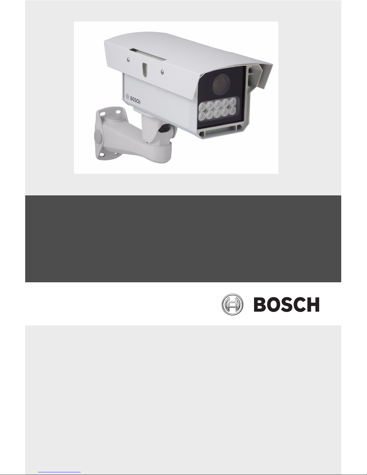
2 Description
The DINION capture is a specialty camera designed to capture
consistent, high-quality images of vehicle license plates.
Available in IP and analog versions, it is ideal for monitoring
parking lots, public areas, and for controlling vehicle access.
The DINION capture overcomes the problems encountered
when using conventional surveillance cameras in vehicle
identification and automatic license plate recognition
applications. The Night Capture Imaging System delivers a
burst of infrared illumination and simultaneously filters out
visible light to ensure clear license plate images in complete
darkness while eliminating the negative effects of headlight
glare.
Advanced Ambient Compensation minimizes plate
overexposure from sunlight for more accurate automatic license
plate recognition. Finally, adjustable imaging modes allow for
fine-tuning the imager for specific regions or license plate
recognition algorithms.
2.1 Parts List
Quantity Description
1 DINION capture 5000 IP
1 3 mm Hex Key
1 5 mm Hex Key
1 Mounting Template
1 CD, containing product documentation and
support files
DINION capture 5000 IP Installing the DINION capture | en 19
Bosch Security Systems, Inc. Installation Manual | 1.0 | 2012.01
3 Installing the DINION capture
This section provides instructions for mounting and wiring the
DINION capture.
3.1 Determining the Range
The DINION capture has a recommended operation range with
specified optimal capture distance for each model as shown
below. Installation should aim to control the traffic through one
lane.
Ranges based on capturing:
520 x 115 mm (approximate) license plates on PAL units
(xER-L2Ry-1)
12 x 6 in. (approximate) license plates on NTSC units
(xER-L2Ry-2)
Field of View at Optimal Capture Distance:
2.8 x 2.1 m (PAL units)
6 ft 6 in. x 4 ft 11 in. (NTSC units)
CAUTION!
The selected mounting location should not place the camera in
a situation where its environmental specifications could be
exceeded.
Ensure the selected location is protected from falling objects,
accidental contact with moving objects, and unintentional
interference from personnel. Follow all applicable building
codes.

20 en | Installing the DINION capture DINION capture 5000 IP
| 1.0 | 2012.01 Installation Manual Bosch Security Systems, Inc.
Table 3.1 Ranges for DINION capture 5000 IP Imagers
3.2 Determining the Angle
The maximum mounting angle of the license plate camera to the
car is 40° for speeds up to 160 km/h (100 mph), both
horizontally and vertically. This angle limits the amount of skew
of the letters on the number plate. If the letters are skewed too
much they will start to become unrecognizable and will reduce
automatic software recognition rates.
For maximum performance ensure the mounting angle is as
narrow as possible. To capture vehicle speeds up to 225 km/h
(140 mph) the horizontal and vertical mounting angle should be
less than 30°.
Model Capture
Range
Optimal
Distance
HFOV VFOV
NER-L2R1-1 3.8–6.4 m
(12.5–21.0 ft)
4.9 m
(16.0 ft)
31.9° 24.2°
NER-L2R1-2 23.0° 17.3°
NER-L2R2-1 5.5–9.1 m
(18–30 ft)
7.1 m
(23.1 ft)
22.3° 16.8°
NER-L2R2-2 16.0° 12.0°
NER-L2R3-1 7.9–13.7 m
(26–45 ft)
10.2 m
(33.5 ft)
15.6° 11.8°
NER-L2R3-2 11.1° 8.3°
NER-L2R4-1 11.3–19.5 m
(37–64 ft)
14.8 m
(48.4 ft)
10.8° 8.1°
NER-L2R4-2 7.7° 5.8°
NER-L2R5-1 16.5–28.0 m
(54–92 ft)
21.3 m
(70.0 ft)
7.5° 5.6°
NER-L2R5-2 5.3° 4.0°
DINION capture 5000 IP Installing the DINION capture | en 21
Bosch Security Systems, Inc. Installation Manual | 1.0 | 2012.01
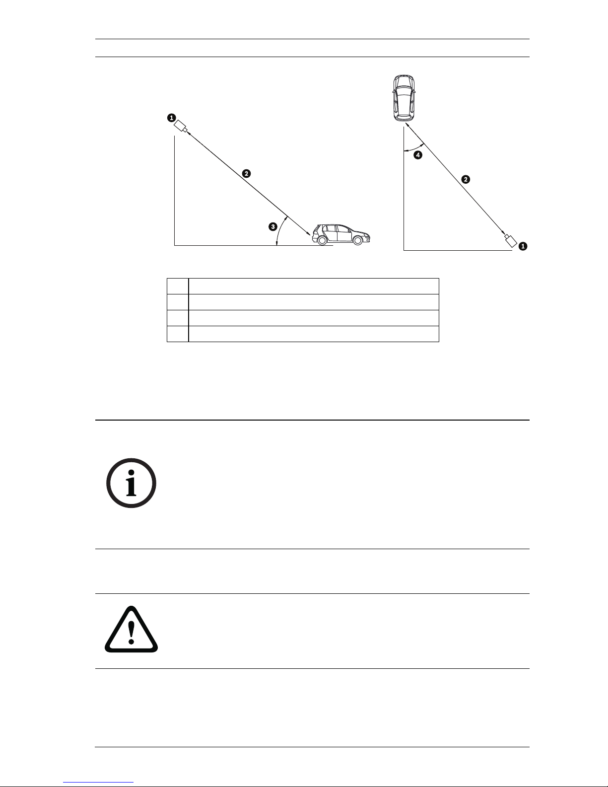
Figure 3.1 Recommended Vertical and Horizontal Mounting Angle
If the maximum range is exceeded, then the letters become
smaller and more difficult to read. At the maximum range and
angle the width of the number plate covers approximately 12%
of the width of the screen.
3.3 Mounting the DINION capture
For a secure mounting installation, bolts should extend through
the mounting surface and be secured with nuts, washers, and
lock washers on the opposite side. If studs are used, they
1 DINION capture
2 Capture Range
3 Vertical Mounting Angle
4 Horizontal Mounting Angle
NOTICE!
The Capture Range is the distance from the license plate
camera to the license plate. Working below the optimal capture
distance allows a larger area for number plates and more
accurate recognition but less lane area can be covered. If the
imager is too close to the license plate, the plate could
disappear from the field of view before it is captured.
CAUTION!
Installation should only be performed by a qualified service
professional in accordance with the National Electrical Code or
applicable local codes.
22 en | Installing the DINION capture DINION capture 5000 IP
| 1.0 | 2012.01 Installation Manual Bosch Security Systems, Inc.
should be anchored in concrete or welded to a steel backer
plate.
Refer to the MBE Mounts and Adapters Installation Guide for
more details about attaching the bracket to an MBE-15 Pole
Mount Adapter or to the MBE-17 Wall Mount Adapter.
1. Use the wall mount template supplied in the packaging box
to locate the four mounting holes for the camera bracket.
2. Drill four (4) holes for the mounting bolts. If installing
outdoors, apply a weatherproof sealant around each hole
at the mounting surface.
3. Route the cable. If routing the cable through the wall, drill
a 25.4 mm (1 in.) hole following the wall mount template
and use a weatherproof sealant to seal around the cable to
ensure a weather tight seal between indoors and outdoors,
otherwise route the cable through one of the side holes in
the mounting bracket by removing the plug and routing the
cable through.
4. Secure the mounting bracket to the mounting surface. Use
four (4) corrosion-resistant, stainless steel studs or bolts,
nuts, washers, and lock washers (not supplied).
5. Adjust the license plate camera angle using the range and
angle recommendations in Section 3.1 Determining the
Range, page 19.
– Connect the imager to a local monitor to assist
adjusting the license plate camera. For DINION
capture 5000 IP cameras, refer to Section 3.4.3 Video
Connection for Installation, page 25.
WARNING!
A stud/bolt diameter of 6.0 mm (or 1/4 inch) able to withstand
a 300 kg (660 lb) pull-out force is recommended. The mounting
material must be able to withstand this pull out force.
DINION capture 5000 IP Installing the DINION capture | en 23
Bosch Security Systems, Inc. Installation Manual | 1.0 | 2012.01
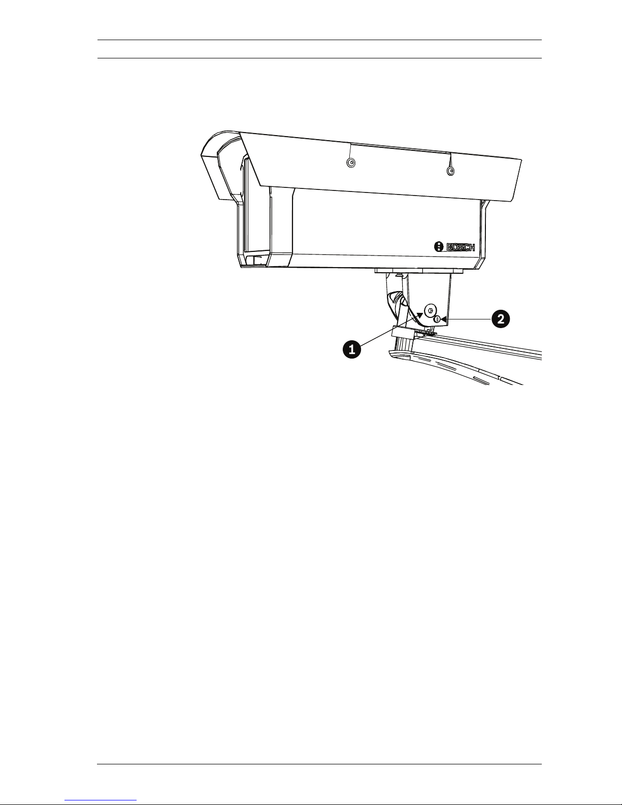
6. Adjust the tilt angle of the camera by loosening the tilt bolt
(item 1, below) with the 5 mm hex key and the set screw
(item 2) with a flat head screwdriver.
7. Place the license plate camera at the desired tilt angle and
tighten the tilt bolt and the set screw.
8. Adjust the pan angle of the camera by loosening the pan
bolt, located beneath the bracket mounting head, by
loosening the pan bolt using the 5 mm hex key. Place the
license plate camera at the desired pan angle and tighten
the bolt.
24 en | Installing the DINION capture DINION capture 5000 IP
| 1.0 | 2012.01 Installation Manual Bosch Security Systems, Inc.
3.4 Preparing the Wiring
The DINION capture 5000 IP is pre-wired with a 2-m long power
input lead and 10/100 Ethernet cable with a male RJ45
connection. The DINION capture 5000 IP can accept power via
the Ethernet cable compliant with the Power-over-Ethernet+
(PoE+ IEEE 802.3at) standard or from a Class 2 power supply.
NOTICE!
For purposes of evaluation and testing of the mounting
bracket's integrity under static loading at CSA, the unit was
mounted to a drywall surface as per the procedures below:
– Locate a stud in the wall and mark the outside edges of the
stud.
– Using the wall mount bracket as a template, align the
mounting hole with the center of the stud.
– Mark the point on the wall in the center of the hole where
the mounting bolt will be positioned.
– Remove the wall mount bracket and drill a pilot hole at the
marked point.
– Align the wall mount bracket mounting hole with the hole
drilled in the wall.
– Using a screwdriver, secure the wall mount bracket by
screwing a 2.5 in. screw with washer securely into the
stud.
– Follow this procedure to attach the three remaining
screws.
NOTICE!
The camera has not been evaluated for safety requirements
using other mounting kits.
CAUTION!
Before proceeding, disconnect the power from the power
supply cable. Ensure that the voltage of the unit matches the
voltage and type of the power supply being used.

DINION capture 5000 IP Installing the DINION capture | en 25
Bosch Security Systems, Inc. Installation Manual | 1.0 | 2012.01
3.4.1 Power Input Connections
A voltage regulator circuit allows for DC or AC operation
between 11-30 VDC and 24 VAC. It also provides protection
from voltage surges, transient spikes, and reversed voltage.
Connect power from a 24 VAC or 11–30 VDC Class 2 power
supply to the ferrule tipped power leads (red, black) from the
camera. Use minimum AWG18 stranded wire.
Note:
For a Class 2 AC/DC supply the polarity does not matter.
3.4.2 Ethernet and Power Connections
– Connect the camera to a 10/100 Base-T network.
– Use screened UTP Category 5e cable with RJ45 connectors
(the camera network socket is Auto MDIX compliant).
– Power can be supplied to the camera via the Ethernet
cable compliant with the Power-over-Ethernet Plus
(IEEE 802.3at) standard.
Three power options, PoE+, 24 VAC, and 11–30 VDC are
available. Using PoE+ makes installation easier and more costeffective, as cameras do not require a local power source. To
increase system reliability, the camera can be simultaneously
connected to both PoE+ and 11-30 VDC/24 VAC supplies.
By default, power is supplied to the camera via the 11–30 VDC
or 24 VAC power input leads.
3.4.3 Video Connection for Installation
To assist in setting up the camera, the DINION capture 5000 IP
provides a BNC connect on the back panel. Use this BNC
connector to temporarily connect a monitor to the IP camera,
refer to Section 3.6 Connecting to a Coax Cable, page 27.

26 en | Installing the DINION capture DINION capture 5000 IP
| 1.0 | 2012.01 Installation Manual Bosch Security Systems, Inc.
3.5 Making the Connections
The easiest way to connect the cables is as follows:
1. Bring the building connections through the surface cable
hole so that they hang clear.
2. Connect the Ethernet cable with connector to RJ-45 jack
coming from the DINION capture 5000 IP.
3. Connect the ferrule tipped power wires (red, black;
polarity independent) to the power supply connection if
power is not supplied via PoE+ over the Ethernet cable.
Note: You can connect the imager to a PoE+ and to an 1130 VDC / 24 VAC supply simultaneously.
4. In damp environments ensure that the connections are
sealed inside a junction box or a field wiring box with
NEMA 3 or IP55 protection level or better. Make the
connections inside the water tight compartment. After
connections are made ensure that the watertight
compartment is tightly closed and cables and conduits are
properly sealed to prevent ingress of water.
WARNING!
Before proceeding, disconnect the power from the power
supply cable. Ensure that the voltage of the unit matches the
voltage and type of the power supply being used.
DINION capture 5000 IP Installing the DINION capture | en 27
Bosch Security Systems, Inc. Installation Manual | 1.0 | 2012.01
3.6 Connecting to a Coax Cable
You can temporarily connect the DINION capture 5000 IP to a
monitor via a coax cable to view the transmitted image for
setup and testing purposes.
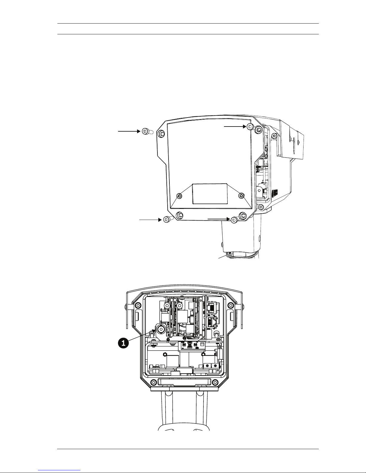
1. Remove the four (4) hex socket screws from the back
panel using the supplied 3 mm hex key.
2. Locate the BNC connector (item 1, below) inside the
imager and connect a coax cable.
28 en | Installing the DINION capture DINION capture 5000 IP
| 1.0 | 2012.01 Installation Manual Bosch Security Systems, Inc.
3. Connect the other end of the coax cable to a monitor.
4. Ensure that power is restored to the imager.
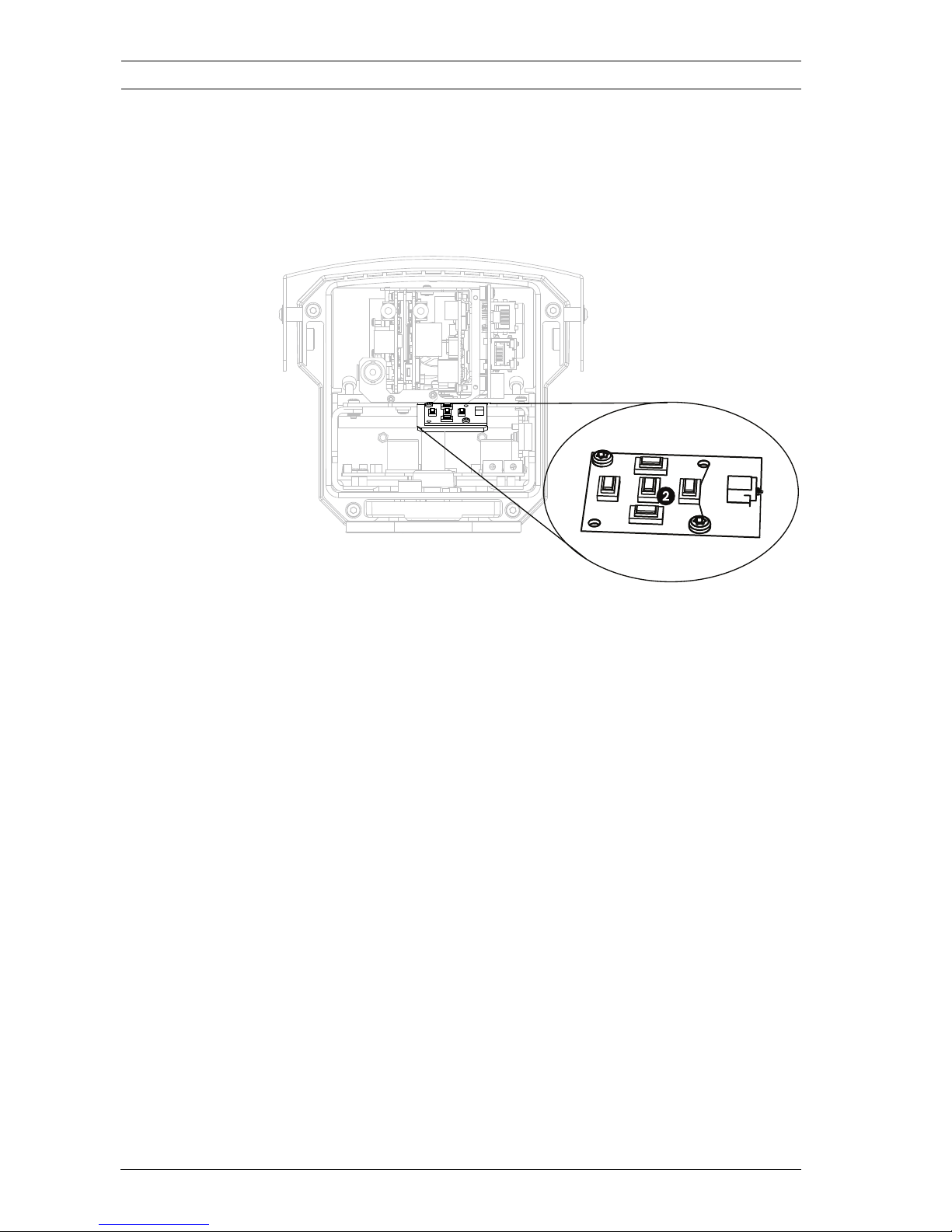
5. Press and hold the center key (item 2) for approximately
two seconds. The BNC video output is activated and the
Install menu appears on the monitor.
6. Adjust settings and setup camera positioning as required.
7. Press and hold the center key a second time to return the
video signal back to the Ethernet connection. Release the
button once the BNC connection loses the video signal.
8. Replace the back panel using the four hex socket screws
and the supplied 3 mm hex key.
3.7 Using a microSD Card
The DINION capture 5000 IP supports most microSD cards
(SDHC). For a list of recommended cards (not supplied by
Bosch), please visit www.boschsecurity.com.
To insert a microSD card:
DINION capture 5000 IP Installing the DINION capture | en 29
Bosch Security Systems, Inc. Installation Manual | 1.0 | 2012.01
1. Remove the back panel of the DINION capture 5000 IP.
Refer to Section 3.6 Connecting to a Coax Cable, page 27 for
instructions.
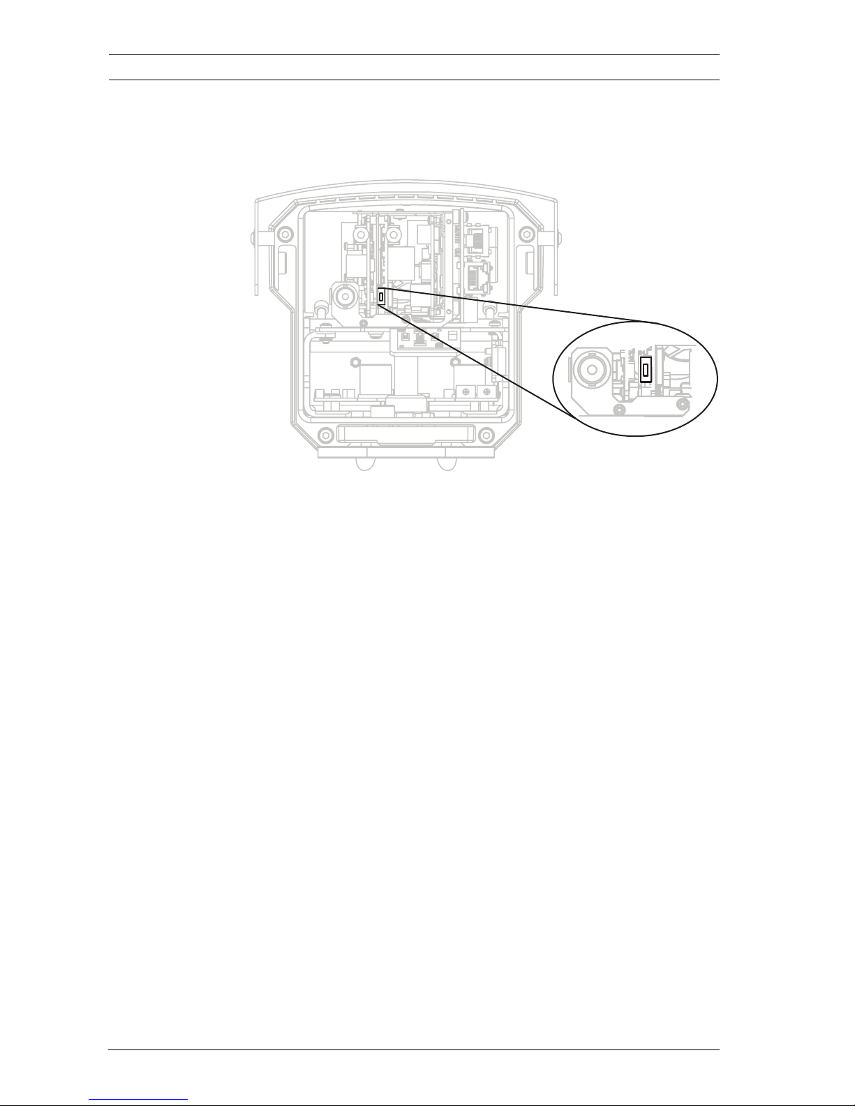
2. Slide the SD card into the slot, located near the center of
the imager.
3. Replace the rear panel.
4. Refer to Section 8.5 Recording, page 78, for more
information on using the microSD card.
3.8 Resetting the DINION capture 5000 IP
You may need to restore the default IP address or restore a
previous version of the Bosch Video over IP (BVIP) firmware on
the DINION capture 5000 IP.
To reset the imager:
30 en | Installing the DINION capture DINION capture 5000 IP
| 1.0 | 2012.01 Installation Manual Bosch Security Systems, Inc.
1. Remove the back panel. Refer to Section 3.6 Connecting to
a Coax Cable, page 27 for instructions.
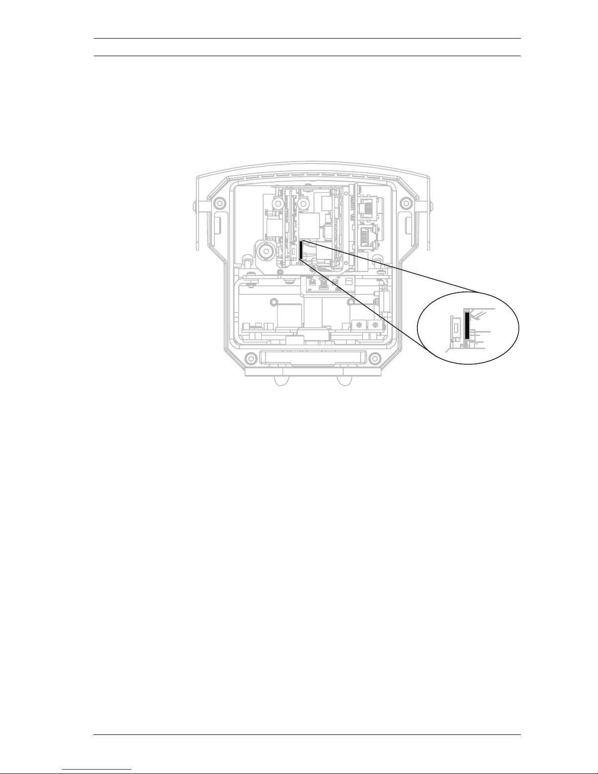
2. Locate the reset button, towards the center of the imager.
3. With the power on, press and hold the reset button for
more than ten (10) seconds to restore the factory defaults.
4. Replace the rear panel.
3.9 Automatic Mode Switching
Automatic Mode Switching is a feature on the license plate
camera that automatically compensates for bright conditions.
Automatic Mode Switching, by default, operates by switching
from Mode 1 (Normal) to Mode 2 (FullSun) when the ambient
light levels rise above normal conditions (for example, bright
sunlight on the scene). Automatic Mode Switching is inactive by
default and requires setup to operate as desired.
In most conditions, Automatic Mode Switching may not be
necessary. Activate the switch only if the license plate camera
operates as desired during darker conditions but overexposes
the image during sunny conditions.
IMPORTANT: Only setup Automatic Mode Switching if the
target license plate is in the sun and the captured image is
overexposed, never setup if the license plate is in the shade.
 Loading...