

Bosch NBC-455-28V User Manual
Dinion IP Camera
NBC-455
en Installation and Operation Manual


Dinion IP Camera Table of Contents | en 3
Table of Contents
1Safety 8
1.1 Safety precautions 8
1.2 Important safety instructions 9
1.3 Connection in applications 10
1.4 FCC & ICES compliance 11
1.5 UL certification 13
1.6 Bosch notices 14
1.7 Copyrights 15
2 Introduction 16
2.1 Features 16
3 System Information 18
3.1 Overview of functions 18
3.1.1 Progressive scan 18
3.1.2 Tri-streaming 18
3.1.3 ONVIF (Open Network Video Interface Forum) 18
3.1.4 Audio 18
3.1.5 Alarm I/O 18
3.1.6 Tamper detection and motion detectors 19
3.1.7 Video encoding 19
3.1.8 Multicast 19
3.1.9 Power-over-Ethernet 19
3.1.10 Data interface 19
3.1.11 Encryption 19
3.1.12 Receiver 20
3.1.13 Recording 20
3.1.14 Snapshots 20
3.1.15 Backup 20
3.1.16 Configuration 20
3.2 Operation with external systems 21
Bosch Security Systems Installation and Operation Manual AR18-10-B006 | v1.1 | 2010.06

4 en | Table of Contents Dinion IP Camera
4 Planning 23
4.1 Unpacking 23
4.2 System requirements 24
4.3 Install players 25
5 Installation 26
5.1 Network (and power) connector 26
5.2 Power connector 27
5.3 Alarm and relay connector 28
5.4 Audio connectors 29
5.5 Video service monitor connector 30
5.6 Data connector 31
5.7 Lens mounting 32
5.8 Mounting the camera 33
5.9 Using the camera install menu 34
5.10 Back focus adjustment 34
5.11 Lens adjustment 35
5.11.1 DC-iris lens 35
5.11.2 Manual-iris lens 35
5.11.3 Video-iris lens 36
5.12 Reset button 36
6 Camera set-up 37
6.1 Camera menu navigation 37
6.2 Install menu 38
6.2.1 Lens Wizard submenu 38
6.2.2 Network submenu 40
6.2.3 Defaults submenu 40
7 Browser connection 41
7.1 System requirements 41
7.2 Establishing the connection 42
7.2.1 Password protection in camera 42
7.3 Protected network 42
7.4 Connecting to a hardware decoder 43
AR18-10-B006 | v1.1 | 2010.06 Installation and Operation Manual Bosch Security Systems

Dinion IP Camera Table of Contents | en 5
7.4.1 Alarm connection 43
7.5 Connection established 44
7.5.1 LIVEPAGE 44
7.5.2 RECORDINGS 44
7.5.3 SETTINGS 44
8 Basic Mode 46
8.1 Basic Mode menu tree 46
8.2 Device Access 47
8.2.1 Camera name 47
8.2.2 Password 47
8.3 Date/Time 48
8.4 Network 49
8.5 Encoder Profile 50
8.6 Audio 50
8.7 Recording 50
8.7.1 Storage medium 50
8.8 System Overview 50
9 Advanced Mode 51
9.1 Advanced Mode menu tree 51
9.2 General 53
9.2.1 Identification 53
9.2.2 Password 53
9.2.3 Date/Time 54
9.2.4 Display Stamping 56
9.3 Web Interface 58
9.3.1 Appearance 58
9.3.2 LIVEPAGE Functions 59
9.3.3 Logging 60
9.4 Encoder 61
9.4.1 Privacy Masks 61
9.4.2 Encoder Profile 61
9.4.3 Encoder Streams 65
9.5 Audio 66
9.6 Camera 67
Bosch Security Systems Installation and Operation Manual AR18-10-B006 | v1.1 | 2010.06

6 en | Table of Contents Dinion IP Camera
9.6.1 ALC 67
9.6.2 Enhance 68
9.6.3 Color 68
9.6.4 Installer Options 69
9.7 Recording 70
9.7.1 Storage Management 70
9.7.2 Recording Profiles 73
9.7.3 Retention Time 74
9.7.4 Recording Scheduler 75
9.7.5 Recording Status 76
9.8 Alarm 77
9.8.1 Alarm Connections 77
9.8.2 Video Content Analyses (VCA) 80
9.8.3 VCA configuration- Profiles 81
9.8.4 VCA configuration - Scheduled 87
9.8.5 VCA configuration - Event triggered 89
9.8.6 Audio Alarm 90
9.8.7 Alarm E-Mail 91
9.8.8 Alarm Task Editor 93
9.9 Interfaces 94
9.9.1 Alarm input 94
9.9.2 Relay 94
9.9.3 COM1 95
9.10 Network 96
9.10.1 Network 96
9.10.2 Advanced 100
9.10.3 Multicasting 101
9.10.4 JPEG Posting 102
9.10.5 Encryption 103
9.11 Service 104
9.11.1 Maintenance 104
9.11.2 Licenses 106
9.11.3 System Overview 106
10 Operation via the browser 107
10.1 Livepage 107
AR18-10-B006 | v1.1 | 2010.06 Installation and Operation Manual Bosch Security Systems

Dinion IP Camera Table of Contents | en 7
10.1.1 Processor load 107
10.1.2 Image selection 108
10.1.3 View Control 108
10.1.4 Digital I/O 108
10.1.5 System Log / Event Log 108
10.1.6 Saving snapshots 108
10.1.7 Recording video sequences 109
10.1.8 Running recording program 109
10.1.9 Audio communication 109
10.2 Recordings page 110
10.2.1 Controlling playback 110
11 Troubleshooting 112
11.1 Function test 112
11.2 Resolving problems 113
11.3 Customer service 115
12 Maintenance 116
12.1 Testing the network connection 116
12.2 Communication with Terminal Program 116
12.3 Repairs 118
12.3.1 Transfer and disposal 118
13 Technical Data 119
13.1 Specifications 119
13.1.1 Dimensions 122
13.1.2 Accessories 123
Glossary 124
Bosch Security Systems Installation and Operation Manual AR18-10-B006 | v1.1 | 2010.06
8 en | Safety Dinion IP Camera
1Safety
1.1 Safety precautions
DANGER!
High risk: This symbol indicates an imminently hazardous
situation such as "Dangerous Voltage" inside the product.
If not avoided, this will result in an electrical shock, serious
bodily injury, or death.
WARNING!
Medium risk: Indicates a potentially hazardous situation.
If not avoided, this could result in minor or moderate bodily
injury.
CAUTION!
Low risk: Indicates a potentially hazardous situation.
If not avoided, this could result in property damage or risk of
damage to the unit.
AR18-10-B006 | v1.1 | 2010.06 Installation and Operation Manual Bosch Security Systems

Dinion IP Camera Safety | en 9
1.2 Important safety instructions
Read, follow, and retain for future reference all of the following
safety instructions. Follow all warnings on the unit and in the
operating instructions before operating the unit.
1. Clean only with a dry cloth. Do not use liquid cleaners or
aerosol cleaners.
2. Do not install unit near any heat sources such as radiators,
heaters, stoves, or other equipment (including amplifiers)
that produce heat.
3. Never spill liquid of any kind on the unit.
4. Take precautions to protect the unit from power and
lightning surges.
5. Adust only those controls specified in the operating
instructions.
6. Operate the unit only from the type of power source
indicated on the label.
7. Unless qualified, do not attempt to service a damaged unit
yourself. Refer all servicing to qualified service personnel.
8. Install in accordance with the manufacturer's instructions
in accordance with applicable local codes. Use only
attachments/accessories specified by the manufacturer.
Equipment change or modification could void the user's
guarantee or authorization agreement.
Bosch Security Systems Installation and Operation Manual AR18-10-B006 | v1.1 | 2010.06
10 en | Safety Dinion IP Camera
1.3 Connection in applications
Power lines: An outdoor system should not be located in the
vicinity of overhead power lines, electrical lights, or power
circuits, or where it may contact such power lines or circuits.
When installing an outdoor system, extreme care should be
taken to keep from touching power lines or circuits, as this
contact may be fatal.
U.S.A. models only - refer to the National Electrical Code Article
820 regarding installation of CATV systems.
12 VDC / 24 VAC power source: This unit is intended to
operate with a limited power source. The unit is intended to
operate at either 12 VDC or 24 VAC (if PoE is not available).
User supplied wiring must be in compliance with electrical
codes (Class 2 power levels). If 24 VAC is used, do not ground
the 24 VAC supply at the terminals or at the unit's power supply
terminals.
PoE: Use only approved PoE devices. Power-over-Ethernet can
be connected at the same time as a 12 VDC or 24 VAC power
supply.
CAUTION!
The Low Voltage power supply unit must comply with EN/UL
60950. The power supply must be a SELV-LPS unit or a SELV Class 2 unit (Safety Extra Low Voltage - Limited Power Source).
AR18-10-B006 | v1.1 | 2010.06 Installation and Operation Manual Bosch Security Systems

Dinion IP Camera Safety | en 11
1.4 FCC & ICES compliance
FCC & ICES Information
(U.S.A. and Canadian Models Only)
This equipment has been tested and found to comply with the
limits for a Class B digital device, pursuant to part 15 of the
FCC Rules. These limits are designed to provide reasonable
protection against harmful interference in a residential
installation. This equipment generates, uses, and can radiate
radio frequency energy and, if not installed and used in
accordance with the instructions, may cause harmful
interference to radio communications. However, there is no
guarantee that interference will not occur in a particular
installation. If this equipment does cause harmful interference
to radio or television reception, which can be determined by
turning the equipment off and on, the user is encouraged to try
to correct the interference by one or more of the following
measures:
– reorient or relocate the receiving antenna;
– increase the separation between the equipment and
receiver;
– connect the equipment into an outlet on a circuit different
from that to which the receiver is connected;
– consult the dealer or an experienced radio/TV technician
for help.
Intentional or unintentional modifications, not expressly
approved by the party responsible for compliance, shall not be
made. Any such modifications could void the user's authority to
operate the equipment. If necessary, the user should consult
the dealer or an experienced radio/television technician for
corrective action.
The user may find the following booklet, prepared by the
Federal Communications Commission, helpful: How to Identify
and Resolve Radio-TV Interference Problems. This booklet is
available from the U.S. Government Printing Office,
Washington, DC 20402, Stock No. 004-000-00345-4.
Bosch Security Systems Installation and Operation Manual AR18-10-B006 | v1.1 | 2010.06

12 en | Safety Dinion IP Camera
Informations FCC et ICES
(modèles utilisés aux États-Unis et au Canada uniquement)
Suite à différents tests, cet appareil s'est révélé conforme aux
exigences imposées aux appareils numériques de classe B, en
vertu de la section 15 du règlement de la Commission fédérale
des communications des États-Unis (FCC), et en vertu de la
norme ICES-003 d'Industrie Canada. Ces exigences visent à
fournir une protection raisonnable contre les interférences
nuisibles lorsque l'appareil est utilisé dans le cadre d'une
installation résidentielle. Cet appareil génère, utilise et émet
de l'énergie de radiofréquences et peut, en cas d'installation ou
d'utilisation non conforme aux instructions, engendrer des
interférences nuisibles au niveau des radiocommunications.
Toutefois, rien ne garantit l'absence d'interférences dans une
installation particulière. Il est possible de déterminer la
production d'interférences en mettant l'appareil
successivement hors et sous tension, tout en contrôlant la
réception radio ou télévision. L'utilisateur peut parvenir à
éliminer les interférences éventuelles en prenant une ou
plusieurs des mesures suivantes:
– Modifier l'orientation ou l'emplacement de l'antenne
réceptrice;
– Éloigner l'appareil du récepteur;
– Brancher l'appareil sur une prise située sur un circuit
différent de celui du récepteur;
– Consulter le revendeur ou un technicien qualifié en radio/
télévision pour obtenir de l'aide.
Toute modification apportée au produit, non expressément
approuvée par la partie responsable de l'appareil, est
strictement interdite. Une telle modification est susceptible
d'entraîner la révocation du droit d'utilisation de l'appareil.
La brochure suivante, publiée par la Commission fédérale des
communications (FCC), peut s'avérer utile : Comment identifier
et résoudre les problèmes d’interférences de radio et de télévision.
Cette brochure est disponible auprès du U.S. Government
Printing Office, Washington, DC 20402, États-Unis, sous la
référence n° 004-000-00345-4.
AR18-10-B006 | v1.1 | 2010.06 Installation and Operation Manual Bosch Security Systems
Dinion IP Camera Safety | en 13
1.5 UL certification
Disclaimer
Underwriter Laboratories Inc. ("UL") has not tested the
performance or reliability of the security or signaling aspects of
this product. UL has only tested fire, shock and/or casualty
hazards as outlined in UL's Standard(s) for Safety for Information
Technology Equipment, UL 60950-1. UL Certification does not
cover the performance or reliability of the security or signaling
aspects of this product.
UL MAKES NO REPRESENTATIONS, WARRANTIES, OR
CERTIFICATIONS WHATSOEVER REGARDING THE
PERFORMANCE OR RELIABILITY OF ANY SECURITY OR
SIGNALING RELATED FUNCTIONS OF THIS PRODUCT.
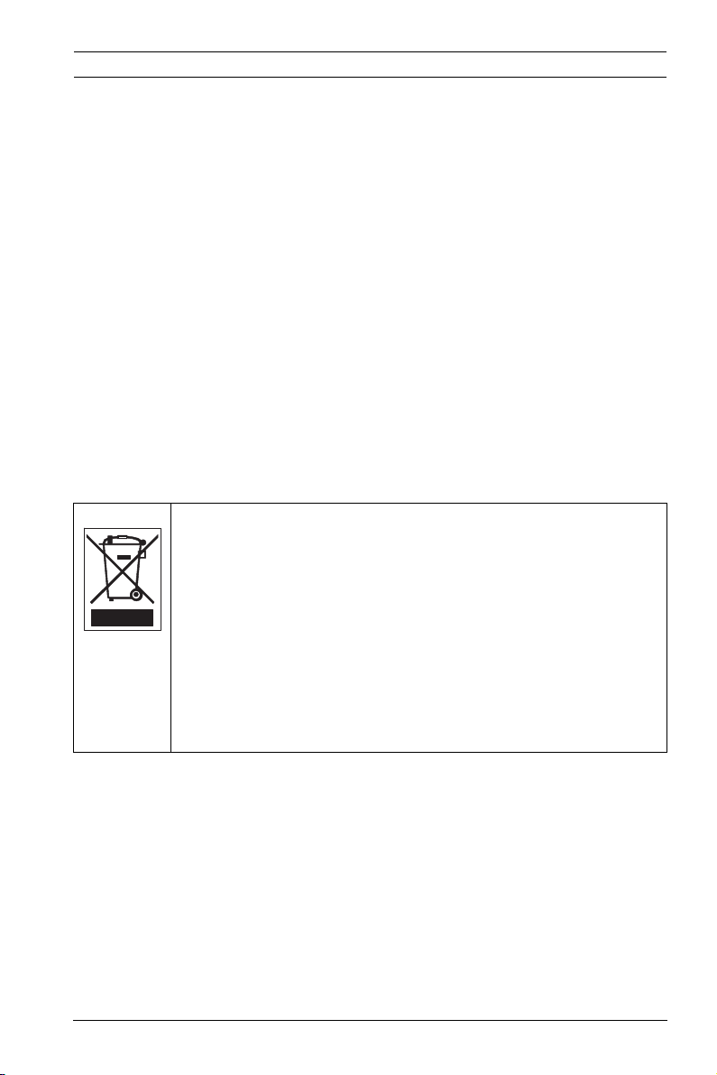
Disposal - Your Bosch product was developed and
manufactured with high-quality material and components that
can be recycled and reused. This symbol means that
electronic and electrical appliances, which have reached the
end of their working life, must be collected and disposed of
separately from household waste material. Separate collecting
systems are usually in place for disused electronic and
electrical products. Please dispose of these units at an
environmentally compatible recycling facility, per European
Directive 2002/96/EC
Bosch Security Systems Installation and Operation Manual AR18-10-B006 | v1.1 | 2010.06

14 en | Safety Dinion IP Camera
1.6 Bosch notices
Video loss
Video loss is inherent to digital video recording; therefore,
Bosch Security Systems cannot be held liable for any damage
that results from missing video information. To minimize the
risk of lost digital information, Bosch Security Systems
recommends multiple, redundant recording systems, and a
procedure to back up all analog and digital information.
Copyright
This manual is the intellectual property of Bosch Security
Systems and is protected by copyright.
All rights reserved.
Trademarks
All hardware and software product names used in this
document are likely to be registered trademarks and must be
treated accordingly.
Note
This manual has been compiled with great care and the
information it contains has been thoroughly verified. The text
was complete and correct at the time of printing. The ongoing
development of the products may mean that the content of the
user guide can change without notice. Bosch Security Systems
accepts no liability for damage resulting directly or indirectly
from faults, incompleteness or discrepancies between the user
guide and the product described.
More information
For more information please contact the nearest Bosch Security
Systems location or visit www.boschsecurity.com
AR18-10-B006 | v1.1 | 2010.06 Installation and Operation Manual Bosch Security Systems

Dinion IP Camera Safety | en 15
1.7 Copyrights
The firmware 4.1 uses the fonts "Adobe-Helvetica-Bold-RNormal--24-240-75-75-P-138-ISO10646-1" and "AdobeHelvetica-Bold-R-Normal--12-120-75-75-P-70-ISO10646-1" under
the following copyright:
Copyright 1984-1989, 1994 Adobe Systems Incorporated.
Copyright 1988, 1994 Digital Equipment Corporation.
Permission to use, copy, modify, distribute and sell this
software and its documentation for any purpose and without
fee is hereby granted, provided that the above copyright
notices appear in all copies and that both those copyright
notices and this permission notice appear in supporting
documentation, and that the names of Adobe Systems and
Digital Equipment Corporation not be used in advertising or
publicity pertaining to distribution of the software without
specific, written prior permission.
This software is based in part on the work of the Independent
JPEG Group.
Bosch Security Systems Installation and Operation Manual AR18-10-B006 | v1.1 | 2010.06

16 en | Introduction Dinion IP Camera
2 Introduction
2.1 Features
The Dinion IP camera is a professional color camera. The
camera incorporates 10-bit digital signal processing for
professional picture performance in natural or artificial lighting
conditons.
The camera uses H.264 compression technology to give clear
images while reducing bandwidth and storage requirements. It
is also ONVIF compliant to improve compatibility during system
integration.
The camera operates as a network video server and transmits
video and control signals over data networks, such as Ethernet
LANs and the Internet.
The camera is easy to install and ready to use.
Features include:
– Progressive scan
– Color performance with NightSense
– 1/3-inch CCD sensor
– Tri-streaming (two H.264 streams and one M-JPEG stream)
– Complies with the ONVIF standard for wide compatibility
– Two-way audio and audio alarm
– Alarm input and alarm output to external devices
– Enhanced video motion detection
– Video and data transmission over IP data networks
– Multicast function for simultaneous picture transmission to
multiple receivers
– Integrated Ethernet interface (10/100 Base-T)
– Power-over-Ethernet (PoE)
– Remote control of all built-in functions via TCP/IP
– Data interface RS485/RS422/RS232 for control of pan or
tilt heads or motorized zoom lenses (PTZ control)
– Password protection to prevent unauthorized connection
or configuration changes
– Event-driven, automatic connection (for example, at
switch-on and for alarms)
AR18-10-B006 | v1.1 | 2010.06 Installation and Operation Manual Bosch Security Systems

Dinion IP Camera Introduction | en 17
– Fast, convenient configuration using the integrated Web
server and a browser
– Firmware update through flash memory
– Convenient upload and download of configuration data
Bosch Security Systems Installation and Operation Manual AR18-10-B006 | v1.1 | 2010.06

18 en | System Information Dinion IP Camera
3 System Information
3.1 Overview of functions
The camera incorporates a network video server. Its primary
function is to encode video and control data for transmission
over an IP network. With its H.264 encoding, it is ideally suited
for IP communication and for remote access to digital video
recorders and IP systems. The use of existing networks means
that integration with CCTV systems or local networks can be
achieved quickly and easily. Video images from a single camera
can be simultaneously received on several receivers.
3.1.1 Progressive scan
The camera captures and processes progressively scanned
images. When there is fast motion in a scene, progressively
scanned images are generally sharper than interlaced images.
3.1.2 Tri-streaming
Tri-streaming allows the data stream to be encoded
simultaneously according to three different, individually
customized profiles. This creates two full H.264 streams that
can serve different purposes and an additional M-JPEG stream.
3.1.3 ONVIF (Open Network Video Interface Forum)
The camera complies to the ONVIF standard which means that
it is easier to install and integrate into larger systems. The
ONVIF standard is a global standard for the interface of network
video products.
3.1.4 Audio
Two-way duplex audio is available in the unit for live voice
communications or audio recording.
3.1.5 Alarm I/O
The alarm input can be used to control the functionality of the
unit. An alarm output can control external devices.
AR18-10-B006 | v1.1 | 2010.06 Installation and Operation Manual Bosch Security Systems

Dinion IP Camera System Information | en 19
3.1.6 Tamper detection and motion detectors
The camera offers a wide range of configuration options for
alarm signaling in the event of tampering with the camera. An
algorithm for detecting movement in the video image is also
part of the scope of delivery and can optionally be extended to
include special video analysis algorithms.
3.1.7 Video encoding
The camera uses the H.264 compression standards. Thanks to
efficient encoding, the data rate remains low even with high
image quality and can also be adapted to local conditions
within wide limits.
3.1.8 Multicast
In suitably configured networks, the multicast function enables
simultaneous, real time transmission to multiple receivers. The
prerequisite for this is that the UDP and IGMP V2 protocols are
implemented on the network.
3.1.9 Power-over-Ethernet
Power for the camera can be supplied via a Power-overEthernet compliant network cable connection. With this
configuration, only a single cable connection is required to
view, power, and control the camera.
3.1.10 Data interface
An external communications port with RS485/RS422/RS232 is
available to provide data to external devices, such as pan and
tilt heads, for full PTZ control via the Ethernet interface.
3.1.11 Encryption
The unit offers a variety of options for protection against
unauthorized reading. Web browser connections can be
protected using HTTPS. Protect the control channels via the
SSL encryption protocol. With an additional license, the user
data itself can be encrypted.
Bosch Security Systems Installation and Operation Manual AR18-10-B006 | v1.1 | 2010.06

20 en | System Information Dinion IP Camera
3.1.12 Receiver
H.264 compatible hardware decoders can be used as a
receiver. Computers with decoding software such as VIDOS, or
computers with the Microsoft Internet Explorer web browser
installed, can also be used as receivers.
3.1.13 Recording
The camera can be used with an iSCSI server connected via the
network to store long-term recordings.
3.1.14 Snapshots
Individual video frames (snapshots) can be called up as JPEG
images, stored on the hard drive, or displayed in a separate
browser window.
3.1.15 Backup
The browser application has an icon for saving the video images
provided by the unit as a file on your computer's hard drive.
Clicking this icon stores the video sequences and they can be
replayed with the Player from Bosch Security Systems included
with the package.
3.1.16 Configuration
The camera can be configured using a browser on the local
network (Intranet) or from the Internet. Similarly, firmware
updates and rapid loading of device configurations are also
possible. Configuration settings can be stored as files on a
computer and copied from one camera to another.
AR18-10-B006 | v1.1 | 2010.06 Installation and Operation Manual Bosch Security Systems

Dinion IP Camera System Information | en 21
3.2 Operation with external systems
The camera can be used with a variety of Bosch software and
hardware systems:
– Bosch Video Management System
– VIDOS video management software
– DiBos 900 Series digital video recorder
– Divar 700 Series digital video recorder
Note:
When connected to any of these systems, many of the camera
configuration parameters are controlled by the system and not
by the settings made via a web browser connected to the
camera.
Bosch Video Management System
The Bosch Video Management System is a unique enterprise IP
video surveillance solution that provides seamless management
of digital video, audio, and data across any IP network. It is
designed to work with Bosch CCTV products as part of a total
video surveillance management system. Integrate your existing
components into one easy-to-manage system, or use Bosch’s
full-line capabilities and benefit from a complete surveillance
solution based on cutting-edge technology and years of
experience.
VIDOS
The camera video server and VIDOS software combine to
provide a high-performance system solution. VIDOS is software
for operating, controlling, and administering CCTV installations
(such as surveillance systems) at remote locations. It runs
under Microsoft Windows operating systems. Its main job is
decoding video, audio, and control data from a remote
transmitter. There are many options available for operation and
configuration when using a camera with VIDOS.
DiBos 900 Series
The camera is also designed for use with DiBos 900 Series
Video Recorders. DiBos can record up to 32 video and audio
Bosch Security Systems Installation and Operation Manual AR18-10-B006 | v1.1 | 2010.06

22 en | System Information Dinion IP Camera
streams, and is available as software or as a hybrid DVR with
additional analog camera and audio inputs. DiBos supports
various functions of the camera, such as controlling relays,
remote control of peripheral devices, and remote configuration.
DiBos can use alarm inputs to trigger actions and, when motion
detection Motion+ is active, can record the relevant cells,
making intelligent motion detection possible.
Divar 700 Series
The Divar 700 Series of digital video recorders can view and
record images from the camera via a network connection. The
Divar 700 Series controls the camera so that the correct
settings are used.
AR18-10-B006 | v1.1 | 2010.06 Installation and Operation Manual Bosch Security Systems

Dinion IP Camera Planning | en 23
4 Planning
4.1 Unpacking
Unpack carefully and handle the equipment with care. The
packaging contains:
– Dinion IP camera
– CCD protection cap (mounted on camera)
– Power connector
– Alarm I/O connector
– Data connector
– DVD ROM (mini)
–Manual
– System requirements
– Configuration Manager
–BVIP Lite Suite
–MPEG ActiveX control
–DirectX control
– Microsoft Internet Explorer
– Sun JVM
– Player and Archive Player
– Adobe Acrobat Reader
– Quick install instructions
– Safety instructions
If equipment has been damaged during shipment, repack it in
the original packaging and notify the shipping agent or supplier.
Bosch Security Systems Installation and Operation Manual AR18-10-B006 | v1.1 | 2010.06

24 en | Planning Dinion IP Camera
4.2 System requirements
– Computer with Windows XP/Vista operating system,
network access, and Microsoft Internet Explorer web
browser version 7.0 or later
or
– Computer with Windows XP/Vista operating system,
network access and reception software, for example
VIDOS, Bosch VMS, or DIBOS 900 Series
or
– H.264 compatible hardware decoder from
Bosch Security Systems (such as VIP XD) as a receiver and
a connected video monitor
or
– Divar 700 Series Digital Video Recorder
The minimum PC requirements are:
– Operating platform: A PC running Windows XP or
Windows Vista with IE 7.0
– Processor: Dual core, 3.0 GHz
– RAM memory: 256 MB
– Monitor resolution: 1024 x 768
– Network interface: 100-BaseT
– DirectX: 9.0c
Make sure the graphics card is set to 16-bit or 32-bit color
depth and that Sun JVM is installed on your PC. To play back
live video images, an appropriate ActiveX must be installed on
the computer. If necessary, install the required software and
controls from the product DVD provided. For further assistance,
contact your PC system administrator.
AR18-10-B006 | v1.1 | 2010.06 Installation and Operation Manual Bosch Security Systems

Dinion IP Camera Planning | en 25
4.3 Install players
Play back saved-video sequences using the Player from
Bosch Security Systems. This can be found on the DVD-ROM
supplied.
to play back saved sequences using the Player, suitable ActiveX
software must be installed on the computer.
1. Insert the DVD into the DVD-ROM drive of the computer. If
the DVD does not start automatically, open the DVD in
Windows Explorer and double-click the index.html file to
start the installation.
2. Select a language from the list box at the top.
3. Click Tools in the menu.
4. Click Archive Player; the installation starts.
5. Follow the instructions in the installation program. The
Archive Player is installed together with the Player.
6. After a successful installation, two new icons for the Player
and the Archive Player appear on the desktop.
7. Double-click the Player icon to start the Player.
Bosch Security Systems Installation and Operation Manual AR18-10-B006 | v1.1 | 2010.06
26 en | Installation Dinion IP Camera
5 Installation
CAUTION!
Installation should only be performed by qualified service
personnel in accordance with the National Electrical Code or
applicable local codes.
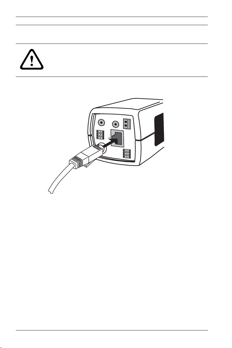
5.1 Network (and power) connector
AUDIO IN
ALARM
1
2
3
VIDEO
UTP Cat 5 RJ45
AUDIO OUT
E
4
T
5
H
6
P
o
E
–
+
12 VDC
24 VAC
DATA
1
4
2
5
3
6
Figure 5.1 Network connection
– Connect the camera to a 10/100 Base-T network.
– Use screened UTP Category 5e cable with RJ45 connectors
(the camera network socket is Auto MDIX compliant).
– Power can be supplied to the camera via the Ethernet
cable compliant with the Power-over-Ethernet
(IEEE 802.3af) standard.
The multicolored LED beside the Ethernet connection indicates
Power (red), IP connection (green) and IP traffic (green
flashing). It can be disabled in the Settings/Camera Settings/
Install options menu.
By default, power is supplied to the camera via the Ethernet
cable, compliant with the Power-over-Ethernet standard.
AR18-10-B006 | v1.1 | 2010.06 Installation and Operation Manual Bosch Security Systems
Dinion IP Camera Installation | en 27
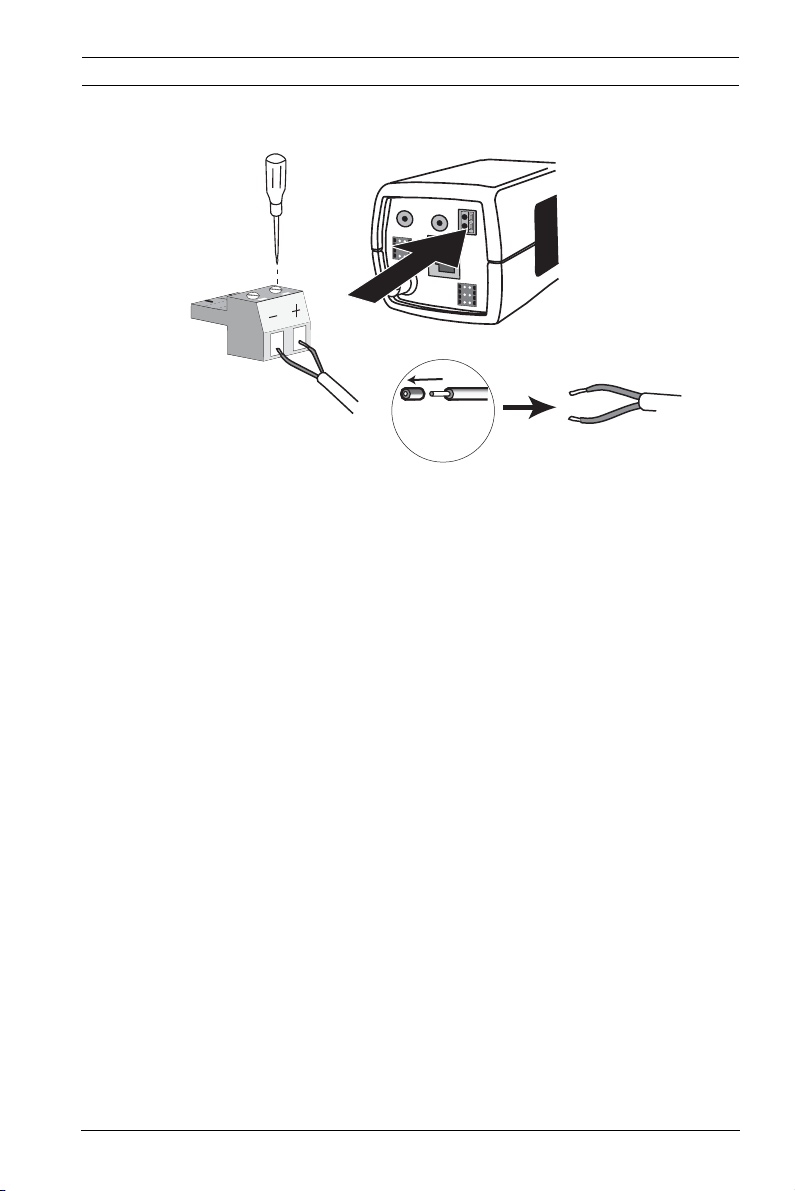
5.2 Power connector
AUDIO IN
AUDIO OUT
–
ALARM
1
4
2
5
3
6
VIDEO
5 mm
0.2 in
Figure 5.2 Power connection
Connect power from a 24 VAC or 12 VDC class 2 power supply
as follows:
– Use AWG16 to 22 stranded wire or AWG16 to 26 solid
wire; cut back 5 mm (0.2 in) of insulation.
– Loosen the screws of the supplied 2-pole connector and
insert the wires.
– Tighten the screws and insert the 2-pole connector into
the power socket of the camera.
+
E
12 VDC
T
24 VAC
H
P
o
E
DATA
1
4
2
5
3
6
Note:
For a DC supply the polarity is important. Incorrect polarity
does not damage the camera but it will not switch on.
Bosch Security Systems Installation and Operation Manual AR18-10-B006 | v1.1 | 2010.06
28 en | Installation Dinion IP Camera
Alarm
1
2
3
4
5
6
5 mm
(0.2 in)
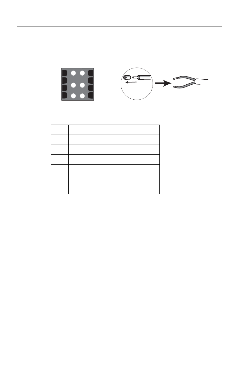
5.3 Alarm and relay connector
Figure 5.3 Alarm and relay connector pins
Pin Alarm socket
1 Alarm in 1
2 Alarm in 2
3 Relay out contact 1
4Ground
5Ground
6 Relay out contact 2
– Max. wire diameter AWG 22-28 for both stranded and
solid; cut back 5 mm (0.2 in) of insulation.
– Alarm output relay switching capability: Max voltage 30VAC
or +40 VDC. Max 0.5 A continuous, 10 VA.
– Alarm in: TTL logic, +5V nominal, +40 VDC max, DC coupled
with 22 kOhm pull-up to +3.3 V.
– Alarm in: configurable as active low or active high.
– Max. 42 V allowed between camera ground and each of the
relay pins.
Use the alarm input to connect external alarm devices such as
door contacts or sensors. A zero potential make-contact or
switch can be used as the actuator (use a bounce-free contact
system).
Use the alarm relay output for switching external devices such
as lamps or sirens.
AR18-10-B006 | v1.1 | 2010.06 Installation and Operation Manual Bosch Security Systems
Dinion IP Camera Installation | en 29
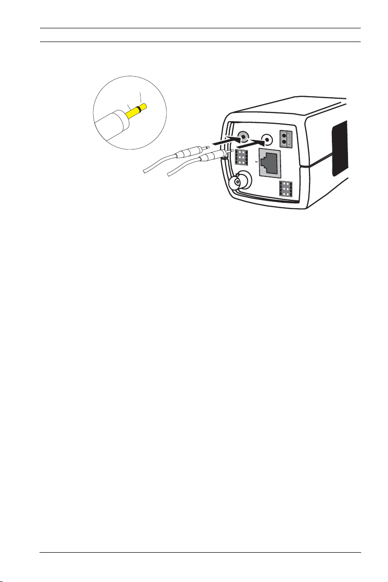
5.4 Audio connectors
Line
GND
AUDIO IN
AUDIO OUT
ALARM
E
1
4
T
2
5
H
3
6
P
VIDEO
o
E
Figure 5.4 Audio connectors
Connect audio devices to the Audio In and Audio Out
connectors.
The unit has full-duplex mono audio. The two-way
communication can be used to connect a speaker or door
intercom system. The audio input signal is transmitted in sync.
with the video signal.
–
+
12 VDC
24 VAC
DATA
1
4
2
5
3
6
Audio input: Line input level (not suitable for direct
microphone signal); impedance 9 kOhm typical; 5.5 Vpp
maximum input voltage.
Audio output: Line output level (not suitable for direct speaker
connection); impedance 16 Ohm minimum; 3 Vpp maximum
output voltage.
Wiring: Shielded audio connection cable is advised. Observe
maximum cable lengths for audio line input and output levels.
Bosch Security Systems Installation and Operation Manual AR18-10-B006 | v1.1 | 2010.06
30 en | Installation Dinion IP Camera
1
2
3
4
5
6
E
T
H
P
o
E
ALARM
AUDIO IN
AUDIO OUT
VIDEO
DATA
1
2
3
4
5
6
–
+
12 VDC
24 VAC
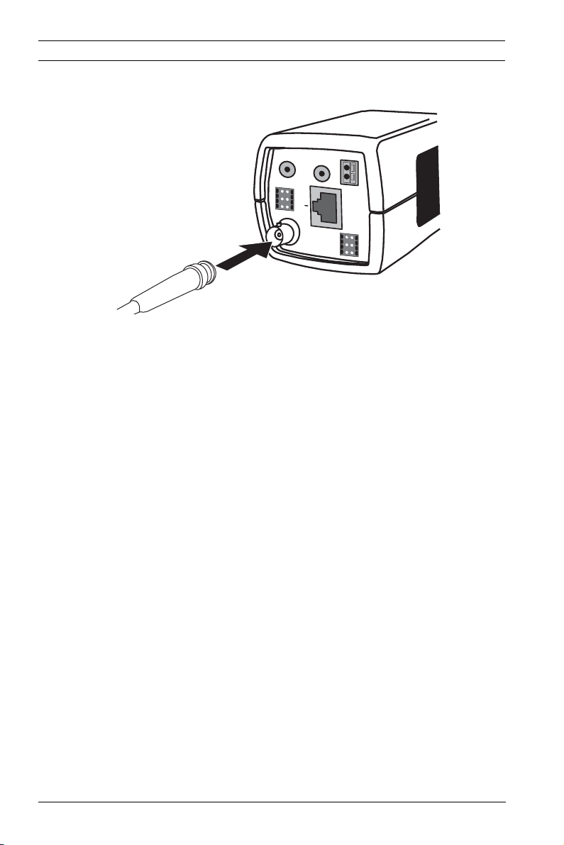
5.5 Video service monitor connector
Figure 5.5 Video BNC connector
1. Connect a service monitor to the composite video BNC
connector to aid installation.
2. Open the side panel on the camera and press the center
button for longer than 2 seconds. This stops the IP video
stream and enables the video analog output.
AR18-10-B006 | v1.1 | 2010.06 Installation and Operation Manual Bosch Security Systems
 Loading...