

Bosch MBE-28B, MBE-27B, MBE-27W, MBE-17W, MBE-17B Installation Manual
...
MBE Mounts and Adapters
MBE Series
en Installation Guide

MBE Mounts and Adapters Table of Contents | en 3
Bosch Security Systems, Inc. Installation Guide | 3.0 | 2011.10
Table of Contents
1 Important safety instructions 4
2 MBE Series Mounts and Adapters 6
2.1 Unpacking 6
2.2 Parts Lists 7
3 MBE-27/28 Wall Mount Applications 8
3.1 Mounting the MBE-27/28 to a Wall 8
3.2 Mounting the MBE-27/28 with the MBE-17 Wall Adapter 9
4 MBE-27/28 Pole Mount Applications 12
5 Attaching Cameras to the Brackets 15
5.1 Attaching an EX27 to the MBE-27 15
5.2 Attaching a REG-D1/L1 to an MBE-28 17
6 Dimensional Outlines 20
4 en | Important safety instructions MBE Mounts and Adapters
| 3.0 | 2011.10 Installation Guide Bosch Security Systems, Inc.
1 Important safety instructions
Type numbers:
DANGER!
High risk: This symbol indicates an imminently hazardous
situation such as “Dangerous Voltage” inside the product.
If not avoided, this will result in an electrical shock, serious
bodily injury, or death.
WARNING!
Medium risk: Indicates a potentially hazardous situation.
If not avoided, this could result in minor or moderate bodily
injury.
CAUTION!
Low risk: Indicates a potentially hazardous situation.
if not avoided, this could result in property damage or risk of
damage to the unit.

MBE Mounts and Adapters Important safety instructions | en 5
Bosch Security Systems, Inc. Installation Guide | 3.0 | 2011.10
Read, follow, and retain all of the following safety instructions.
Heed all warnings on the unit and in the operating instructions
before operation.
1. Clean only with a dry cloth. Do not use liquid cleaners or
aerosol cleaners.
2. Do not install unit near any heat sources such as radiators,
heaters, stoves, or other equipment (including amplifiers)
that produce heat.
3. Adjust only those controls specified in the operating
instructions.
4. Unless qualified, do not attempt to service a damaged unit
yourself. Refer all servicing to qualified service personnel.
5. Use only replacement parts specified by the manufacturer.
6. Install in accordance with the manufacturer's instructions
in accordance with applicable local codes.
7. Use only attachments/accessories specified by the
manufacturer. Equipment change or modification could
void the user's guarantee or authorization agreement.
You can view and print the full version of this Installation
Manual with Adobe Acrobat Reader, available online. This user
guide is the intellectual property of Bosch Security Systems;
protected by copyright. Contact: www.boschsecurity.com

6 en | MBE Series Mounts and Adapters MBE Mounts and Adapters
| 3.0 | 2011.10 Installation Guide Bosch Security Systems, Inc.
2 MBE Series Mounts and Adapters
This manual describes the following MBE series mounting
brackets and adapters:
MBE-27B / MBE-27W: a black or white mounting bracket for
use with an EX27 Series All-Weather Camera.
MBE-28B: a black mounting bracket for use with the REG-D1 or
the REG-L1 License Plate Camera.
MBE-15B / MBE-15W: a black or white adapter used to attach
an MBE-27 or MBE-28, along with an EXMB.020B Heavy Duty L
Bracket, to a pole.
This adapter can also accommodate the EXMB.028 Cable
Managed Wall Bracket or the EXMB.023 Wall Bracket.
MBE-17B / MBE-17W: a black or white adapter used to attach
an MBE-27 or an MBE-28, along with an EXMB.020B Heavy Duty
L-Bracket, to a wall.
This adapter can also accommodate the EXMB.028 Cable
Managed Wall Bracket or the EXMB.023 Wall Bracket.
Refer to Section 6 Dimensional Outlines, page 20, for
dimensional drawings of each mount and adapter.
2.1 Unpacking
This equipment should be unpacked and handled with care. If
an item appears to have been damaged in shipment, notify the
shipper immediately.
Verify that all the parts listed in the product's Parts List below
are included. If any items are missing, notify your Bosch
Security Systems Sales or Customer Service Representative.
The original packing carton is the safest container in which to
transport the unit and must be used if returning the unit for
service. Save it for possible future use.
MBE Mounts and Adapters MBE Series Mounts and Adapters | en 7
Bosch Security Systems, Inc. Installation Guide | 3.0 | 2011.10
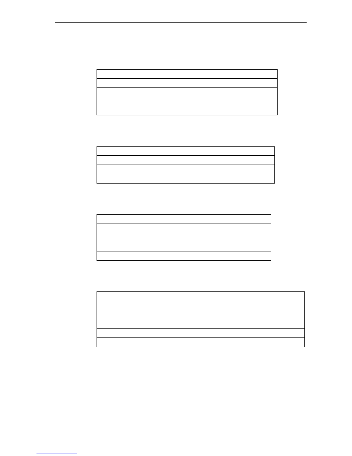
2.2 Parts Lists
MBE-15B / MBE-15W Pole Mount Adapter
MBE-17B / MBE-17W Wall Mount Adapter
MBE-27B / MBE-27W Wall Mount Bracket
MBE-28B Wall Mount Bracket
Quantity Description
1 Pole mount adapter plate, black or white
2 Metal bands with gear clamps
4 M6 x 20 mm bolts
4 M6 flat washers
Quantity Description
1 Wall mount adapter plate, black or white
4 M6 x 20 mm bolts
4 M6 flat washers
Quantity Description
1 Bracket arm for EX27, black or white
1 #6 Hex Key
1 EX27 interface plate
1 M8 x 45 mm bolt
Quantity Description
1 Bracket arm for REG-D1/REG-L1, black
1 #4 hex key
1 #5 hex key
6 M5 x 10 mm bolts (attached to bracket)
6 M5 plastic captive washers (attached to bracket)
8 en | MBE-27/28 Wall Mount Applications MBE Mounts and Adapters
| 3.0 | 2011.10 Installation Guide Bosch Security Systems, Inc.
3 MBE-27/28 Wall Mount Applications
The MBE-27B, MBE-27W, and the MBE-28B Brackets can be
mounted directly to a wall or to the MBE-17 Wall-Mount
Adapter. The MBE-17 Wall-Mount Adapter provides extra
support and can withstand heavier loads.
The MBE-28 Bracket also allows cables to run through the arm
and up the mount head at the end of the arm to connect to the
camera.
For a secure mounting installation, bolts should extend through
the mounting surface and be secured with nuts, washers, and
lock washers on the opposite side.
If studs are used, they should either be anchored in concrete or
welded to a steel backer plate.
3.1 Mounting the MBE-27/28 to a Wall
The MBE-27/28 can be mounted directly to a wall surface and
can support up to 25 kg (55 lbs). Use the MBE-17 wall-mount
adapter if your application requires extra support. Refer to
Section 3.2 Mounting the MBE-27/28 with the MBE-17 Wall
Adapter, page 9.
1. Determine a secure mounting location for the wall
installation.
2. Use the four (4) holes on the flanges of the MBE-27/28
wall-mount bracket as a template to mark the position
where the holes should be drilled to secure the mount.
MBE-28: If routing cables through the wall, drill a 25 mm
(1 in.) hole placed exactly in the middle of the four (4)
marked holes.
CAUTION!
Ensure that the mounting fasteners have a minimum pull-out
strength of 300 kg (661.4 lbs) per screw.
 Loading...