

Page 1
Instruction Manual
EN Pole Mount Adaptors
LTC 9213/01, LTC 9225/00
Page 2

LLTTCC 99221133//0011,, LLTTCC 99222255//0000 ||
Instruction Manual
||
Important Safeguards
EENN
|
2
Bosch Security Systems, Inc. | December 23, 2008
Important Safeguards
1. Read, Follow, and Retain Instructions - All safety
and operating instructions should be read and
followed before operating the unit. Retain instructions
for future reference.
2. Heed Warnings - Adhere to all warnings on the unit
and in the operating instructions.
3. Attachments - Attachments not recommended by
the product manufacturer should not be used, as they
may cause hazards.
4. Installation Cautions - Do not place this unit on an
unstable stand, tripod, bracket, or mount. The unit
may fall, causing serious injury to a person and
serious damage to the unit. Use only manufacturerrecommended accessories, or those sold with the
product. Mount the unit per the manufacturer’s
instructions. Appliance and cart combination should
be moved with care. Quick stops, excessive force, or
uneven surfaces may cause the appliance and cart
combination to overturn.
5. Cleaning - Unplug the unit from the outlet before
cleaning. Follow any instructions provided with the
unit. Generally, using a damp cloth for cleaning is
sufficient. Do not use liquid cleaners or aerosol
cleaners.
6. Servicing - Do not attempt to service this unit
yourself. Opening or removing covers may expose
you to dangerous voltage or other hazards. Refer all
servicing to qualified service personnel.
7. Damage Requiring Service - Unplug the unit from
the main AC power source and refer servicing to
qualified service personnel under the following
conditions:
When the power supply cord or plug is damaged.
If liquid has been spilled or an object has fallen
into the unit.
If the unit has been exposed to water and/or
inclement weather (rain, snow, etc.).
If the unit does not operate normally, when
following the operating instructions. Adjust only
those controls specified in the operating
instructions. Improper adjustment of other controls
may result in damage, and require extensive work
by a qualified technician to restore the unit to
normal operation.
If the unit has been dropped or the cabinet
damaged.
If the unit exhibits a distinct change in
performance, this indicates that service is needed.
8. Replacement Parts - When replacement parts are
required, the service technician should use
replacement parts specified by the manufacturer or
that have the same characteristics as the original part.
Unauthorized substitutions may result in fire,
electrical shock or other hazards.
9. Safety Check - Upon completion of servicing or
repairs to the unit, ask the service technician to
perform safety checks to ensure proper operating
condition.
10. Power Sources - Operate the unit only from the type
of power source indicated on the label. If unsure of
the type of power supply to use, contact your dealer
or local power company.
For units intended to operate from battery power,
refer to the operating instructions.
For units intended to operate with External
Power Supplies, use only the recommended
approved power supplies.
For units intended to operate with a limited power
source, this power source must comply with
EN60950. Substitutions may damage the unit or
cause fire or shock.
For units intended to operate at 24VAC, normal
input voltage is 24VAC. Voltage applied to the
unit’s power input should not exceed 30VAC.
User-supplied wiring, from the 24VAC supply to
unit, must be in compliance with electrical codes
(Class 2 power levels). Do not ground the 24VAC
supply at the terminals or at the unit’s power
supply terminals.
11. Coax Grounding - If an outside cable system is
connected to the unit, ensure that the cable system is
grounded. U.S.A. models only - Section 810 of the
National Electrical Code, ANSI/NFPA No.70,
provides information regarding proper grounding of
the mount and supporting structure, grounding of the
coax to a discharge unit, size of grounding
conductors, location of discharge unit, connection to
grounding electrodes, and requirements for the
grounding electrode.
12 . Grounding - This unit may be equipped with a 3-
wire grounding plug (a plug with a third pin, for
grounding). This safety feature allows the plug to fit
into a grounding power outlet only. If unable to
insert the plug into the outlet, contact an electrician
to arrange replacement of the obsolete outlet. Do not
defeat the safety purpose of the grounding plug.
Outdoor equipment should only be connected to
the unit’s inputs after this unit has had its
grounding plug connected to a grounded outlet or
its ground terminal properly connected to a ground
source.
The unit’s input connectors must be disconnected
from outdoor equipment before disconnecting the
grounding plug or grounding terminal.
Proper safety precautions such as grounding should
be followed for any outdoor device connected to
this unit.
13. Lightning - For added protection during a lightning
storm, or when this unit is left unattended and
unused for long periods of time, unplug the unit from
the wall outlet and disconnect the cable system. This
will prevent damage to the unit due to lightning and
power line surges.
Page 3
LLTTCC 99221133//0011,, LLTTCC 99222255//0000 ||
Instruction Manual
||
Safety Precautions
EENN
|
3
Bosch Security Systems, Inc. | December 23, 2008
Safety Precautions
Installation should be performed by qualified
service personnel only in accordance with the
National Electrical Code or applicable local
codes.
Power Disconnect. Units with or without
ON-OFF switches have power supplied to the
unit whenever the power cord is inserted into the
power source; however, the unit is operational
only when the ON-OFF switch is in the ON
position. The power cord is the main power
disconnect for all units.
CCAAUUTTIIOONN:: TTOO RREEDDUUCCEE TTHHEE RRIISSKK OOFF
EELLEECCTTRRIICC SSHHOOCCKK,, DDOO NNOOTT RREEMMOOVVEE CCOOVVEERR
((OORR BBAACCKK)).. NNOO UUSSEERR SSEERRVVIICCEEAABBLLEE PPAARRTTSS
IINNSSIIDDEE.. RREEFFEERR SSEERRVVIICCIINNGG TTOO QQUUAALLIIFFIIEEDD
SSEERRVVIICCEE PPEERRSSOONNNNEELL..
This symbol indicates the presence of
uninsulated dangerous voltage within the
product s enclosure that can cause an electric
shock.
This symbol indicates the presence of
important operating and maintenance
(servicing) instructions in the literature
accompanying the appliance.
For Indoor Product
1. Water and Moisture - Do not use this unit near
water - for example, in a wet basement, in an
unprotected outdoor installation or in any area
classified as a wet location.
2. Object and Liquid Entry - Never push objects of
any kind into this unit through openings, as they
might touch dangerous voltage points or create
short circuits, resulting in a fire or electrical
shock. Never spill liquid of any kind on the unit.
3. Power Cord and Power Cord Protection - For
units intended to operate with 230VAC, 50Hz,
the input and output power cord must comply
with the latest versions of IEC Publication 227 or
IEC Publication 245.
Power supply cords should be routed so they are
not likely to be walked on or pinched. Pay
particular attention to location of cords and plugs,
convenience receptacles, and the point of exit
from the appliance.
4. Overloading - Do not overload outlets and
extension cords; this can result in a risk of fire or
electrical shock.
For Outdoor Product
Power Lines - An outdoor system should not be
located in the vicinity of overhead power lines,
electric lights or power circuits, or where it may
contact such power lines or circuits. When
installing an outdoor system, extreme care should
be taken to keep from touching power lines or
circuits, as this contact might be fatal. U.S.A.
models only - refer to the National Electrical
Code Article 820 regarding installation of CATV
systems.
For Rack-mount Product
1. Ventilation - Do not place this equipment in a
built-in installation or rack, unless proper
ventilation is provided, or the manufacturer’s
instructions were followed. The equipment must
not exceed its maximum operating temperature
requirements.
2. Mechanical Loading - When rack-mounting the
equipment, ensure that a hazardous condition is
not created by uneven mechanical loading.
Page 4

LLTTCC 99221133//0011,, LLTTCC 99222255//0000 ||
Instruction Manual
||
Safety Precautions
EENN
|
4
Securite
Attention : l’installation doit exclusivement Œtre rØalisØe par du
AATTTTEENNTTIIOONN :: PPOOUURR ÉVVIITTEERR TTOOUUTT RRIISSQQUUEE DD’’ÉLLEECCTTRROOCCUUTTIIOONN,,
NN’’EESSSSAAYYEEZZ PPAASS DDEE RREETTIIRREERR LLEE CCAAPPOOTT ((OOUU LLEE PPAANNNNEEAAUU
AARRRRII¨¨RREE)).. CCEETT AAPPPPAARREEIILL NNEE CCOONNTTIIEENNTT AAUUCCUUNN CCOOMMPPOOSSAANNTT
SSUUSSCCEEPPTTIIBBLLEE DD’’ÊTTRREE RRÉPPAARRÉ PPAARR LL’’UUTTIILLIISSAATTEEUURR.. CCOONNFFIIEEZZ
LLAA RRÉPPAARRAATTIIOONN DDEE LL’’AAPPPPAARREEIILL À DDUU PPEERRSSOONNNNEELL QQUUAALLIIFFIIÉ..
Ce symbole signale que le produit renferme une « tension
potentiellement dangereuse » non isolØe susceptible de
provoquer une Ølectrocution.
Ce symbole invite l’utilisateur consulter les instructions
d’utilisation et d’entretien (dØpannage) reprises dans la
documentation qui accompagne l’appareil.
personnel qualifiØ, conformØment au code national d’ØlectricitØ
amØricain (NEC) ou au code d’ØlectricitØ local en vigueur.
Coupure de l’alimentation. Qu’ils soient pourvus ou non d’un
commutateur ON/OFF, tous les appareils re oivent de l’Ønergie une
fois le cordon branchØ sur la source d’alimentation. Toutefois,
l’appareil ne fonctionne rØellement que lorsque
le commutateur est rØglØ sur ON. Le dØbranchement du cordon
d’alimentation permet de couper l’alimentation des appareils.
Precauciones de Seguridad
PPRREECCAAUUCCIIÓNN:: PPAARRAA DDIISSMMIINNUUIIRR EELL RRIIEESSGGOO DDEE DDEESSCCAARRGGAA
EELLÉCCTTRRIICCAA,, NNOO RREETTIIRREE LLAA CCUUBBIIEERRTTAA ((NNII LLAA PPAARRTTEE
PPOOSSTTEERRIIOORR)).. NNOO EEXXIISSTTEENN PPIIEEZZAASS DDEE RREECCAAMMBBIIOO EENN EELL
IINNTTEERRIIOORR DDEELL EEQQUUIIPPOO.. EELL PPEERRSSOONNAALL DDEE SSEERRVVIICCIIOO
CCUUAALLIIFFIICCAADDOO SSEE EENNCCAARRGGAA DDEE RREEAALLIIZZAARR LLAASS
RREEPPAARRAACCIIOONNEESS..
Este s mbolo indica que existen puntos de tensi n peligrosos
sin aislamiento dentro de la cubierta de la unidad. Estos
puntos pueden constituir un riesgo de descarga elØctrica.
El usuario debe consultar las instrucciones de funcionamiento y
mantenimiento (reparaci n) en la documentaci n que se
suministra con el aparato.
Atenci n: la instalaci n la debe realizar œnicamente personal
cualificado de conformidad con el National Electric Code o las
normas aplicables en su pa s.
Desconexi n de la alimentaci n. Las unidades con o sin
interruptores de encendido/apagado reciben alimentaci n
elØctrica siempre que el cable de alimentaci n estØ conectado a
la fuente de alimentaci n. Sin embargo, la unidad s lo funciona
cuando el interruptor estÆ en la posici n de encendido. El cable
de alimentaci n es la principal fuente de desconexi n de todas
las unidades.
Sicherheitshinweise
VVOORRSSIICCHHTT:: UUMM EEIINNEENN EELLEEKKTTRRIISSCCHHEENN SSCCHHLLAAGG ZZUU
VVEERRMMEEIIDDEENN,, IISSTT DDIIEE AABBDDEECCKKUUNNGG ((OODDEERR RRÜCCKKSSEEIITTEE)) NNIICCHHTT
ZZUU EENNTTFFEERRNNEENN.. EESS BBEEFFIINNDDEENN SSIICCHH KKEEIINNEE TTEEIILLEE IINN DDIIEESSEEMM
BBEERREEIICCHH,, DDIIEE VVOOMM BBEENNUUTTZZEERR GGEEWWAARRTTEETT WWEERRDDEENN KKÖNNNNEENN..
LLAASSSSEENN SSIIEE WWAARRTTUUNNGGSSAARRBBEEIITTEENN NNUURR VVOONN QQUUAALLIIFFIIZZIIEERRTTEEMM
WWAARRTTUUNNGGSSPPEERRSSOONNAALL AAUUSSFFÜHHRREENN..
Das Symbol macht auf nicht isolierte gef hrliche Spannung"
im Geh use aufmerksam. Dies kann zu einem elektrischen
Schlag f hren.
Der Benutzer sollte sich ausf hrlich ber Anweisungen f r
die Bedienung und Instandhaltung (Wartung) in den
begleitenden Unterlagen informieren.
Achtung! Die Installation sollte nur von qualifiziertem
Kundendienstpersonal gem jeweils zutreffender
Elektrovorschriften ausgef hrt werden.
Unterbrechung des Netzanschlusses. Ger te mit oder ohne
Netzschalter haben Spannung am Ger t anliegen, sobald der
Netzstecker in die Steckdose gesteckt wird. Das Ger t ist jedoch
nur betriebsbereit, wenn der Netzschalter (EIN/AUS) auf EIN
steht. Wenn das Netzkabel aus der Steckdose gezogen wird, ist
die Spannungszuf hrung zum Ger t vollkommen unterbrochen.
Veiligheidsmaatregelen
VVOOOORRZZIICCHHTTIIGG:: OOPPEENN DDEE BBEEHHUUIIZZIINNGG OOFF DDEE AACCHHTTEERRKKAANNTT
VVAANN HHEETT AAPPPPAARRAAAATT NNIIEETT.. ZZOO VVEERRMMIINNDDEERRTT UU HHEETT RRIISSIICCOO
OOPP EELLEEKKTTRRIISSCCHHEE SSCCHHOOKKKKEENN.. IINN HHEETT AAPPPPAARRAAAATT
BBEEVVIINNDDEENN ZZIICCHH GGEEEENN OONNDDEERRDDEELLEENN DDIIEE UU ZZEELLFF KKUUNNTT
RREEPPAARREERREENN.. LLAAAATT SSEERRVVIICCEE EENN OONNDDEERRHHOOUUDD UUIITTVVOOEERREENN
DDOOOORR GGEEKKWWAALLIIFFIICCEEEERRDD PPEERRSSOONNEEEELL..
Dit symbool geeft aan dat er binnen in het apparaat
onge soleerde, gevaarlijke spanning aanwezig is die mogelijk
elektrische schokken kan veroorzaken.
De gebruiker dient de bedienings- en onderhoudsvoorschriften
te raadplegen in de documentatie die werd meegeleverd met
het apparaat.
Attentie: het apparaat mag alleen door gekwalificeerd personeel
worden ge nstalleerd. De installatie dient in overeenstemming
met de nationale elektrische richtlijnen of de van toepassing
zijnde lokale richtlijnen te worden uitgevoerd.
Spanning uitschakelen. Apparatuur met of zonder
aan-uitschakelaar staat onder spanning zolang de stekker is
aangesloten op de wandcontactdoos. De apparatuur is uitsluitend
in werking als de aan-uitschakelaar aan staat. Het netsnoer is de
"hoofdschakelaar" voor alle apparatuur.
Bosch Security Systems, Inc. | December 23, 2008
Page 5

EENN
|
5
LLTTCC 99221133//0011,, LLTTCC 99222255//0000 ||
Instruction Manual
Sicurezza
AATTTTEENNZZIIOONNEE:: PPEERR RRIIDDUURRRREE IILL RRIISSCCHHIIOO DDII SSCCOOSSSSEE
EELLEETTTTRRIICCHHEE NNOONN RRIIMMUUOOVVEERREE LLAA CCOOPPEERRTTUURRAA ((OO IILL
PPAANNNNEELLLLOO PPOOSSTTEERRIIOORREE)).. LL’’UUNNIITTÀ NNOONN CCOONNTTIIEENNEE
CCOOMMPPOONNEENNTTII IINNTTEERRNNII RRIIPPAARRAABBIILLII DDAALLLL’’UUTTEENNTTEE.. PPEERR
QQUUAALLSSIIAASSII IINNTTEERRVVEENNTTOO,, RRIIVVOOLLGGEERRSSII AA PPEERRSSOONNAALLEE
TTEECCNNIICCOO QQUUAALLIIFFIICCAATTOO..
Questo simbolo indica la presenza di "tensione pericolosa" non
isolata all’interno del contenitore del prodotto. Ci comporta un
potenziale rischio di scosse elettriche.
Si consiglia di consultare le istruzioni operative e di
manutenzione (interventi tecnici) contenute nella
documentazione fornita con il dispositivo.
Attenzione: l’installazione deve essere effettuata esclusivamente
da personale tecnico qualificato in conformit con il National
Electrical Code o con le normative locali vigenti.
Scollegamento dell’alimentazione. Le unit dotate o sprovviste di
interruttori ON-OFF vengono alimentate quando si inserisce il
cavo nella presa dell’alimentazione. L’unit tuttavia in funzione
solo quando l’interruttore ON-OFF si trova nella posizione ON. Il
cavo di alimentazione costituisce il dispositivo di scollegamento
dell’alimentazione principale per tutte le unit .
||
Safety Precautions
Medidas de Seguranc a
CCUUIIDDAADDOO:: PPAARRAA RREEDDUUZZIIRR OO RRIISSCCOO DDEE CCHHOOQQUUEE
EELLÉCCTTRRIICCOO,, NNˆˆOO RREETTIIRREE AA TTAAMMPPAA ((OOUU AA PPAARRTTEE
PPOOSSTTEERRIIOORR)).. NNOO IINNTTEERRIIOORR,, NNˆˆOO EEXXIISSTTEEMM PPEEÇAASS QQUUEE
PPOOSSSSAAMM SSEERR RREEPPAARRAADDAASS PPEELLOO UUTTIILLIIZZAADDOORR.. RREEMMEETTAA AA
AASSSSIISSTTÊNNCCIIAA PPAARRAA OOSS TTÉCCNNIICCOOSS QQUUAALLIIFFIICCAADDOOSS..
Este s mbolo indica a presen a de "tens o perigosa" n o isolada
dentro da estrutura do produto, o que pode constituir risco de
choque elØctrico.
O utilizador deve consultar as instru ıes de funcionamento
e manuten o (assistŒncia) nos documentos que
acompanham o aparelho.
Aten o: a instala o deve ser executada apenas por tØcnicos
qualificados da assistŒncia, de acordo com o c digo elØctrico
nacional ou os c digos locais aplicÆveis.
Corte de corrente. As unidades com ou sem interruptores
ON-OFF (ligar/desligar) recebem corrente sempre que o fio de
alimenta o estÆ introduzido na fonte de alimenta o; contudo, a
unidade apenas estÆ operacional quando o interruptor ON-OFF
estÆ na posi o ON. O fio de alimenta o destina-se a desligar a
corrente em todas as unidades.
Bosch Security Systems, Inc. | December 23, 2008
Page 6

EENN
|
6
LLTTCC 99221133//0011,, LLTTCC 99222255//0000 ||
Instruction Manual
||
Unpacking
Bosch Security Systems, Inc. | December 23, 2008
1.0 UNPACKING
This equipment should be unpacked and handled with
care. If an item appears to have been damaged in
shipment, notify the shipper.
Verify that all parts shown in the Parts List have been
included. If any items are missing, notify your Bosch
Security Systems Sales or Customer Service
Representative.
The original packing carton is the safest container in
which to transport the unit. Save it for possible future use.
1.1 Parts List
2.0 SERVICE
If the unit needs servicing, contact the nearest Bosch
Security Systems Service Center for authorization to
return and shipping instructions.
Service Centers
USA
Phone: 800-366-2283 or 717-735-6638
Fax: 800-366-1329 or 717-735-6639
CCTV Spare Parts
Phone: 800-894-5215 or 408-956-3853 or 3854
Fax: 408-957-3198
E-mail: BoschCCTVparts@ca.slr.com
Canada
Phone: 514-738-2434
Europe, Middle East & Asia Pacific Region
Phone: 32-1-440-0711
For additional information, see
www.boschsecurity.com
.
3.0 DESCRIPTION
The LTC 9213/00 and LTC 9225/00 Pole Mount
Adapters are designed to permit the installation of
indoor/outdoor wall mounts to a pole capable of
supporting the total weight of equipment installed. The
pole can range from 76 mm (3 in.) to 381 mm (15 in.)
in diameter.
4.0 INSTALLATION
4.1 Mount Compatibility
Pole Mount Suggested Maximum
Adapter Wall Mounts Rated Load
LTC 9213/01 LTC 9212/00 9 kg (20 lb)
LTC 9215/00 9 kg (20 lb)
LTC 9215/00S 9 kg (20 lb)
LTC 9225/00 LTC 9216/00 45 kg (100 lb)
LTC 9222/00 90 kg (200 lb)
4.2 Tools Required
4.2.1 LTC 9213/01 Pole Mount Adapter
8 mm Hex wrench
Banding tool (TC9311PM3T is recommended)
4.2.2 LTC 9225/00 Pole Mount Adapter
12 mm Hex wrench
Banding tool (TC9311PM3T is recommended)
4.3 Mounting
1. Cut the structural band strap into two (2) 1.5 m
(5 ft) straps.
2. Attach the bracket to the pole at the band
desired height using the two (2) straps and the
two (2) buckles provided.
3. Tension the straps according to the instructions
for the banding tool used. Banding tool,
TC9311PM3T, is recommended and may be
purchased separately. A BAND-IT
fi
Tool
instruction chart is provided with each pole
mount. The ends of the bands are bent around
the buckle (see Figure 1).
Figure 1: Bending Method
QQttyy IItteemm
1 Unit (verify model number)
1 This installation manual
1 BAND-ITfi Tool instruction chart
1 Mounting bracket
LTC 9213/01 Hardware kit
1 Structural band strap, 3 m (10 ft)
4 Screw, hex head, M8 x 25
4 Washer, spiral lock, M8
4 Screw, oval head, # 6-32
LTC 9225/00 Hardware kit
1 Structural band strap, 3 m (10 ft), that must be cut into
two (2) 1.5 m (5 ft) lengths
2 Band buckle
6 Screw, hex head, M12 x 35
6 Nut, hex, M12
6 Washer, spiral lock, M2
6 Washer, plain, M12
WARNING: This installation should be made
by a qualified service person and conform to
all local codes.
Tension and
Bend Back Bands
Bend Buckle
Tab Over Bands
Page 7
EENN
|
7
LLTTCC 99221133//0011,, LLTTCC 99222255//0000 ||
Instruction Manual
||
Installation
Bosch Security Systems, Inc. | December 23, 2008
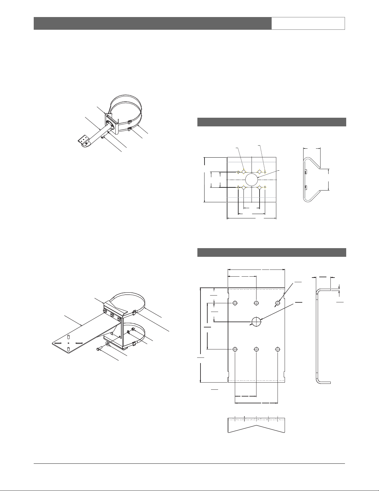
4. For model LTC 9213/01 with an LTC 9212/00,
LTC 9215/00, or an LTC 9215/00S, secure the
wall mount to the pole mount using the four (4)
8 mm screws and lock washers provided. Use
the four larger holes that are in a square pattern
around the center (see Figure 2).
Figure 2: Securing the LTC 9213/01 with an
LTC 9212/00, LTC 9215/00 or an
LTC 9215/00S
5. For model LTC 9213/01 with an LTC 1348/00,
secure the wall mount to the pole mount using
the four (4) No. 6 screws provided. Use the four
(4) smaller holes that are in a rectangular
pattern.
6. For model LTC 9225/00 with an LTC 9216/00
or an LTC 9222/00, secure the wall mount to
the pole mount using the six (6) 12 mm screws,
plain washers, lock washers and nuts provided
(see Figure 3).
Figure 3: Securing the LTC 9225/00 with an
LTC 9216/00 or an LTC 9222/00
5.0 SPECIFICATIONS
5.1 LTC 9213/01, LTC 9225/00
Pole Mount Adapters
Construction: Formed aluminum plate
Finish: Light gray
Weight:
LTC 9213/01: 0.5 kg (1 lb)
LTC 9225/00: 1.4 kg (3 lb)
Band
Buckle
Lock Washer
Screw
Pole Mount
Wall Mount
ÿ
M8 Thread
Typ 4 Places
6-32 Thread
Typ 4 Places
139.1
(5.48)
53.3
(2.10)
66.5
(2.62)
(1.81)
49.4
(1.9 5)
49.4
45.8
(1.9 5)
(6.00)
82.9
(3.27)
152.4
38.4
(1.51)
Hole
mm
(in.)
LTC 9213/01 Pole Mount Adaptor
LTC 9225/00 Pole Mount Adaptor
Pole Mount
Wall Mount
Plain Washer
Screw
Band
Nut
Lock Washer
Buckle
203
8.00
152
6.00
337
13.25
165
6.50
2.13
54
2.64
67
mm
102
4.00
in
3.00
76
0.56
1.25
52
14
32
2.04
0.25
6
Page 8

' 2008 Bosch Security Systems GmbH
F01U122758 | Updated December 23, 2008 | Data subject to change without notice.
BAND-ITfi is a registered trademark of Idex Corporation.
AAmmeerriiccaass
Bosch Security Systems
130 Perinton Parkway
Fairport, New York, 14450, USA
Phone: +1 (585) 223 4060
+1 800 289 0096
security.sales@us.bosch.com
http://www.boschsecurity.us
EEuurrooppee,, MMiiddddllee EEaasstt,, AAffrriiccaa
Bosch Security Systems B.V.
P.O. Box 80002
5600 JB Eindhoven, The Netherlands
Phone: +31 (0) 40 27 83955
Fax: +31 (0) 40 27 86668
emea.securitysystems@bosch.com
http://www.boschsecurity.com
AAssiiaa--PPaacciiffiicc
Bosch Security Systems Pte Ltd
38C Jalan Pemimpin
Singapore 577180
Phone: +65 6319 3450
Fax: +65 6319 3499
apr.securitysystems@bosch.com
http://www.boschsecurity.com
 Loading...