

Bosch LTC 8850 Instruction Manual
Instruction Manual
EN Security Systems
Graphical Users
Interface (GUI) with
Allegiant
®
Server
LTC 8850 Series

LTC 8850 | Instruction Manual | Table of Contents
EN
|
2
Bosch Security Systems | 02 April 2004
Table of Contents
1INTRODUCTION . . . . . . . . . . . . . . . . . . . . . . . . . . . . . . . . . . . . . . . . . . . . . . . . . . . . . . . . . . .3
1.1 Introduction . . . . . . . . . . . . . . . . . . . . . . . . . . . . . . . . . . . . . . . . . . . . . . . . . . . . . . . . . . . . . . . . .3
1.2Overview . . . . . . . . . . . . . . . . . . . . . . . . . . . . . . . . . . . . . . . . . . . . . . . . . . . . . . . . . . . . . . . . . . .3
1.3Getting Started . . . . . . . . . . . . . . . . . . . . . . . . . . . . . . . . . . . . . . . . . . . . . . . . . . . . . . . . . . . . . . .3
1.4 Installation Instructions . . . . . . . . . . . . . . . . . . . . . . . . . . . . . . . . . . . . . . . . . . . . . . . . . . . . . . . .4
1.5 Updating LTC 8902 Series and LTC 8903 Series Firmware . . . . . . . . . . . . . . . . . . . . . . . . . . . .7
1.6 LTC 8850 README File . . . . . . . . . . . . . . . . . . . . . . . . . . . . . . . . . . . . . . . . . . . . . . . . . . . . . .8
2 GUI MAP APPLICATION . . . . . . . . . . . . . . . . . . . . . . . . . . . . . . . . . . . . . . . . . . . . . . . . . . . . .8
2.1 General Information . . . . . . . . . . . . . . . . . . . . . . . . . . . . . . . . . . . . . . . . . . . . . . . . . . . . . . . . . . .8
2.2 Starting the GUI Map Application . . . . . . . . . . . . . . . . . . . . . . . . . . . . . . . . . . . . . . . . . . . . . . .8
2.3 Modifying a User Profile . . . . . . . . . . . . . . . . . . . . . . . . . . . . . . . . . . . . . . . . . . . . . . . . . . . . . . .9
2.4 Starting a New Site Configuration File (Map Page) . . . . . . . . . . . . . . . . . . . . . . . . . . . . . . . . . .10
2.5 Editing and Adding Map Pages . . . . . . . . . . . . . . . . . . . . . . . . . . . . . . . . . . . . . . . . . . . . . . . . .10
2.6 Moving from One Map Page to Another . . . . . . . . . . . . . . . . . . . . . . . . . . . . . . . . . . . . . . . . . .11
2.7 General Map Page Commands . . . . . . . . . . . . . . . . . . . . . . . . . . . . . . . . . . . . . . . . . . . . . . . . . .13
2.8 Adding Server Devices to a Map Page . . . . . . . . . . . . . . . . . . . . . . . . . . . . . . . . . . . . . . . . . . . .14
2.9 Seeding Icons . . . . . . . . . . . . . . . . . . . . . . . . . . . . . . . . . . . . . . . . . . . . . . . . . . . . . . . . . . . . . . .15
2.10 Device Icon Properties . . . . . . . . . . . . . . . . . . . . . . . . . . . . . . . . . . . . . . . . . . . . . . . . . . . . . . . .15
2.11 Window Options . . . . . . . . . . . . . . . . . . . . . . . . . . . . . . . . . . . . . . . . . . . . . . . . . . . . . . . . . . . . .16
2.12 Saving Configuration Files . . . . . . . . . . . . . . . . . . . . . . . . . . . . . . . . . . . . . . . . . . . . . . . . . . . . .17
2.13 Event Handler . . . . . . . . . . . . . . . . . . . . . . . . . . . . . . . . . . . . . . . . . . . . . . . . . . . . . . . . . . . . . . .17
2.14 Help . . . . . . . . . . . . . . . . . . . . . . . . . . . . . . . . . . . . . . . . . . . . . . . . . . . . . . . . . . . . . . . . . . . . . .18
2.15 The Toolbar . . . . . . . . . . . . . . . . . . . . . . . . . . . . . . . . . . . . . . . . . . . . . . . . . . . . . . . . . . . . . . . .19
2.16 Running Server Configuration Programs . . . . . . . . . . . . . . . . . . . . . . . . . . . . . . . . . . . . . . . . . .20
3 ALLEGIANT SERVER . . . . . . . . . . . . . . . . . . . . . . . . . . . . . . . . . . . . . . . . . . . . . . . . . . . . . . .21
3.1 Allegiant Server Icons . . . . . . . . . . . . . . . . . . . . . . . . . . . . . . . . . . . . . . . . . . . . . . . . . . . . . . . . .21
3.2 Allegiant Server Application . . . . . . . . . . . . . . . . . . . . . . . . . . . . . . . . . . . . . . . . . . . . . . . . . . . .27
3.3 Allegiant System Status Application . . . . . . . . . . . . . . . . . . . . . . . . . . . . . . . . . . . . . . . . . . . . . .55
3.4 InWinPTZ Server . . . . . . . . . . . . . . . . . . . . . . . . . . . . . . . . . . . . . . . . . . . . . . . . . . . . . . . . . . . .59
4VCR SERVER . . . . . . . . . . . . . . . . . . . . . . . . . . . . . . . . . . . . . . . . . . . . . . . . . . . . . . . . . . . . . .63
4.1 Introduction . . . . . . . . . . . . . . . . . . . . . . . . . . . . . . . . . . . . . . . . . . . . . . . . . . . . . . . . . . . . . . . .63
4.2 Icon Properties Dialog Box . . . . . . . . . . . . . . . . . . . . . . . . . . . . . . . . . . . . . . . . . . . . . . . . . . . .63
4.3 Communication Setup Dialog Box . . . . . . . . . . . . . . . . . . . . . . . . . . . . . . . . . . . . . . . . . . . . . . .64
4.4 VCR Support . . . . . . . . . . . . . . . . . . . . . . . . . . . . . . . . . . . . . . . . . . . . . . . . . . . . . . . . . . . . . . .64
4.5 Custom VCR Support . . . . . . . . . . . . . . . . . . . . . . . . . . . . . . . . . . . . . . . . . . . . . . . . . . . . . . . .69

EN|3
Bosch Security Systems | 02 April 2004
LTC 8850 | Instruction Manual | Introduction
1INTRODUCTION
1.1 INTRODUCTION
The LTC 8850 GUI, Security Systems Graphical User
Interface with Allegiant Server, brings the familiarity of
the personal computer to those who supervise closed
circuit television systems. Running on a Microsoft
®
Windows based computer, the GUI is the human
interface that makes it quick and easy to configure,
monitor, and control the intricacies of an entire
Allegiant system. This version of the LTC 8850 also
supports control of compatible VCRs (SECTION 4)
and optional control of pan/tilt cameras directly from a
video window on your PC (SECTION 3.4). Additional
server modules can be added for products such as
multiplexers.
Surveillance site maps are stored as pages in a site
configuration. On top of the pages, one can arrange
control icons in any way desired. Pages can be linked
together by placing link icons and configuring those
icons to link to other pages.
With the integrated Allegiant Server, users can set and
change an Allegiant’s system parameters; program
camera sequences; lock cameras, monitors, remotes,
and keyboards from certain users; and perform many
other system control features. Users can also view
system activity with real time monitoring of the system
status. The Allegiant Server communicates with the
Allegiant system through an RS-232 interface.
NOTE: This manual may use LTC 8x00 as a generic
designation for any Allegiant system. In practice, the x
should be replaced with the appropriate digit, for
example, LTC 8300, LTC 8500, or LTC 8800.
1.2 OVERVIEW
The GUI is made up of several integrated
components. Understanding these components, what
they do, and how they work together will make the
installation easier.
Each security system installation is represented in the
GUI as a site configuration. The site configurations
contain one or more maps or layout diagrams of the
site being secured. Multiple site maps are linked
together with link icons that allow traversing between
the maps by clicking on icons.
Also, the maps contain icons that represent actual
security devices, such as cameras and alarm points.
These icons can be used to control the devices. For
example, a camera icon can be used to pan or tilt a
camera.
The maps' pages and link icons are provided by the
main GUI program. The security device icons are
provided by product servers. Although the product
servers provide the underlying functionality, they are
accessed directly through the GUI.
The GUI program can interface with multiple product
servers, simultaneously providing control of multiple
security system products through a single user
interface. This LTC 8850 includes the Allegiant server,
which allows complete configuration and control of the
Allegiant systems through the GUI. Camera, monitor,
alarm, and function icons from the Allegiant server are
placed on the map pages of the site configuration to
provide control.
The GUI provides three access levels that are
determined by a log-in procedure. These levels are
Installer, Administrator, and Operator. Installers are
responsible for setting up the site configurations:
importing maps, adding links between maps, and
placing security device icons. Installers or
Administrators are responsible for configuring the
tables that control the Allegiant. Operators can only
manipulate the system through icons in the site
configuration map.
1.3GETTING STARTED
Before using the Graphical User Interface (GUI),
review the following steps to ensure that the program
will run properly on the host computer. Users should
be familiar with the Allegiant CCTV control system
and Windows-based software as well as their personal
computer and operating system software.
1.3.1 Checking for Completeness
The GUI package contains several components. Use
the following checklist to make sure the package has
been assembled correctly:
• LTC 8850 GUI User Manual (this book)
• CD-ROM
• Software security key
• PC to system interface cable

EN|4
Bosch Security Systems | 02 April 2004
LTC 8850 | Instruction Manual | Introduction
1.3.2 Minimum System Requirements
Before using the GUI, make sure that the host
computer meets the following minimum system
requirements:
• Microsoft Windows compatible PC, Intel
®
Pentium
®
120 MHz or greater
• Windows NT 4.0 (Service Pack 6 or later);
Windows 2000, Windows XP, Windows 95/98/ME
(Note
1
)
• CD-ROM drive
• 32 MB of RAM
• One serial port
• One parallel port configured for bidirectional
operation (Examine BIOS settings if necessary)
• Super VGA display or compatible
• For LTC 8850 Network Configurations:
Windows NT, 2000, or, XP is required on all
workstations. Windows Server is required on PC
attached to Allegiant if number of workstations
exceeds 10.
NOTE
1
: Because of resource limitations imposed by
Windows 95/98/ME, complex site installations (those
having approximately 10 site maps or more) should be
configured only on PCs running Windows NT 4.0,
Windows 2000 or Windows XP.
1.3.3 The Security Key
Before the program will run on the host computer, the
hardware security key must be connected to a parallel
port of the computer. Locate this port (possibly labeled
LPT) with the help of the hardware manual that comes
with the host computer. Make sure the computer is
turned off. Push the security key into place and secure
it with the screws on the key. Be careful not to
overtighten the screws.
A printer or other device can be connected onto the
security key, but the key might not function properly
unless the device is turned on.
In the event the security manager does not wish other
people to gain access to the GUI, the key may be
removed and locked for safekeeping. The GUI will
run in Demo mode without the software key attached.
1.3.4 The Console Interface Cable
For functions that require communication between the
GUI and the main Allegiant system, the supplied
LTC 8506/00 interface cable must connect the host
computer to the Allegiant main bay. Attach the 9-pin
connector on the supplied cable to the port labeled
CONSOLE on the rear of the Allegiant main bay.
Plug the 9-pin connector on the other end of the cable
into an available serial port on the host computer
(PC). This port might be labeled COM1 or COM2. In
order for serial communications to operate properly,
the PC and the Allegiant system must use the same
communication parameters. For reference, the cable
pinouts are as follows:
9-pin Male Allegiant 9-pin Female
(Allegiant Side)
Designation (PC Side)
1 Chassis GND None
2Receive Data 3
3Transmit Data 2
4CTS 1
5RTS 8
6No Connection None
7 Data GND 5
8No Connection None
9No Connection None
(jumper pins 4 & 6)
(jumper pins 1 & 7)
LTC 8506/00 Cable Pinouts
1.4 IN STALLAT ION INSTRUCTIONS
This section provides instructions for installing the
Graphical User Interface (GUI) and the Allegiant
Server. The Allegiant Server requires an Allegiant
System CPU firmware revision that is the same or
higher than listed in the README files. These
instructions explain how to determine the Allegiant
System CPU firmware revision and how to update
older CPU firmware.

EN|5
Bosch Security Systems | 02 April 2004
LTC 8850 | Instruction Manual | Introduction
The installation procedure of the following sections
can be summarized as follows:
1. Install the LTC 8850 Software.
2. Determine your Allegiant CPU Firmware Revision.
3. Update the Allegiant CPU Firmware (if necessary).
4. Run the GUI and establish communications with
the Allegiant System.
5. Download Saved Configuration Data (if necessary).
6. Complete your GUI and Allegiant System setup.
7. N otes on Uploading and Downloading.
1.4.1 Step 1. Install the LTC 8850 Software.
The LTC 8850 software is shipped on CD-ROM.Insert
the CD and wait for the installation dialog box to
automatically appear. If the installation dialog box
does not appear, you can manually browse the CD
and run Setup.exe. It would be wise to exit all other
applications before running the setup program.
If an updated version is to be installed over and older
version, the old version should be uninstalled first.
This is easily done by using the Uninstall LTC 8859
utility found in the existing Allegiant software folder
under the Windows Start menu. After the new version
has been installed, it may also be desirable to
manually move your Allegiant configuration files from
the old \Alleg default directory location to the new
C:\Program Files\Bosch Security
Systems\LTC_8850\Alleg default directory location
using Windows Explorer.
The setup program will create an LTC 8850 program
group with the following items: the GUI, Allegiant
Server, Allegiant Network Host (Windows NT,
Windows 2000,or Windows XP only), MCS Translator
and other programs you need to completely configure
an Allegiant system.
1.4.2 Step 2. Determine your Allegiant CPU
Firmware Revision
There are several ways to determine the revision of
your Allegiant CPU firmware.
Method 1: From an operational Allegiant IntuiKey
Series Keyboard, select the Display CPU Version.
If using a LTC 8555 series keyboard, press
USER 23 ENTER. This displays the revision number
on the monitor currently controlled by the keyboard in
the following format: x.xx
where x.xx specifies the Allegiant firmware revision.
The LTC 8850 README file specifies the minimum
Allegiant CPU firmware that is compatible with the
installed LTC 8850 version. If the Allegiant firmware
revision is less than this, the firmware must be
updated. If the displayed number is a number less then
6.00, or if ERR 15 is displayed instead of a revision
number, the CPU is not a current revision board. In
this case, the CPU board must be replaced with a
current version to work with the GUI.
Method 2: If your system is not yet installed, the
revision can be determined by examining the CPU
board if using LTC 8500, LTC 8600, or LTC 8800
systems. If the CPU board has two 8-position DIP
switches, it is a current board. If not, the CPU board
must be replaced with a current version to work with
the GUI.
If the CPU board is current, examine the socketed ICs
with copyright labels near the batteries. The labels on
these ICs should contain the numbers 303 1029 yxx,
where y will be a number between 0 and 9 or a letter
A-F, and xx will designate the firmware revision. (The
revision number may be followed by -L or -H). If the
firmware revision number is less than required, the
firmware must be updated (see Step 3).
1.4.3 Step 3. Update the Allegiant CPU Firmware
If Step 2 indicated that the Allegiant CPU Firmware
must be updated, then proceed with this step.
Otherwise, move on to Step 4.
The firmware update consists of two steps:
A. Upload and save your existing configuration data.
B. Update the Allegiant CPU Firmware.
1.4.3.1 Step 3-A. Upload And Save Your Existing
Configuration
When Allegiant CPU firmware is updated, the
configuration data in the Allegiant system is cleared. If
you do not wish to save your configuration data, go on
to Step 3-B.
If your Allegiant System was programmed with the
Allegiant Server, double-click the Allegiant Server
icon from the LTC 8850 program group to start the
program. Go online, then upload all tables you want to
preserve. Next, save the Allegiant Server file on your
PC (see later sections in this manual for directions on
uploading and saving).
NOTE: If your Allegiant System was programmed
using DOS-based Master Control Software, your
existing copy of Master Control Software should be
used for uploading and saving your configuration data
(Allegiant Server is not compatible with old CPU
firmware revisions). If you do not have Master Control
Software compatible with your existing firmware, you
should write down any programming information that
will need to be reentered later, then go on to Step 3 B.

EN|6
Bosch Security Systems | 02 April 2004
LTC 8850 | Instruction Manual | Introduction
The LTC 8850 security key cannot be used for DOSbased Master Control Software access. The black key
supplied with the customer's original Master Control
Software should be used.
1.4.3.2 Step 3-B. Update the Allegiant CPU Firmware
The Allegiant CPU firmware is upgraded by running a
program that downloads new operating firmware into
the Allegiant through a PC serial port. Follow the steps
below to perform this procedure:
•Connect the supplied console cable (or a usersupplied cable with the correct pin-out) from your
PC serial port 1 or serial port 2 to the Allegiant
console port (if you already have a console cable
connected, you can skip this step).
•From the Windows START menu, select Programs |
LTC 8850 | MCS Directory. A DOS window will
open.
•Type "download tc####.mot <com port>."
"####" is one of the following {8100, 8200, 8300,
8500, 8600, 8800, 8900}, as appropriate for your
system, and <com port> is the PC com port. Do
not include the quotation marks, and press ENTER
at the end of the line. Follow the directions
provided by the program. The download procedure
may take up to 30 minutes. Make sure that no
errors occur during the download - retry if errors
do occur.
• In rare cases, a download error can put the
Allegiant system into a state where the download
program won't successfully re-establish
communications when it is retried. If this happens,
cycle the power on the Allegiant bay, and try the
download again. If a failure still occurs, locate DIP
switch S1001, S100, or S0201 on the Allegiant
CPU. Turn on DIP switch 5, and retry the
download program. After the download is
successful, turn switch 5 back off and cycle the
Allegiant System power.
1.4.4 Step 4. Run the GUI and Establish
Communications with the Allegiant System
If not already connected, connect the supplied console
cable (or a user-supplied cable with the appropriate
pin-out) from an appropriate PC serial port to the
Allegiant console port.
If not already connected, connect the supplied security
key to the parallel port of your computer. This device
can be connected in series with other security keys. If
multiple security keys are used, they can be inserted in
any order. A printer or other device can then be
connected to the security key. If a printer or other
device is attached, the security key may not function
properly unless the device is turned on. (NOTE: The
latest version of the GUI Allegiant Server version
requires keys later than those distributed with version
numbers 1.0X. Keys that will permit the latest version
to operate have the part numbers 303 1874 020 001
and 303 1874 021 000).
Method 1: Access the Allegiant Server Directly
•Start the Allegiant Server program.
• Log on with User Name Installer, password 1 OR
Administrator password 2.
•Select File | New from the Allegiant Server menu.
•Go to Method 1 and Method 2 Common Steps.
Method 2: Access the Allegiant Server through the
GUI
• Start the GUI program.
• Log on with User Name Installer, Password 1.
•Begin a new site configuration by selecting File |
New from the GUI Menus.
•Start the Allegiant Server by selecting Server |
Allegiant from the GUI Menus.
• The Allegiant Server will then prompt for a
filename for the new Allegiant Configuration. Enter
a filename and press OK. After a short pause, the
GUI will display the Allegiant seedbar.
• Once again, select Server from the GUI menu.
This time, there will be a new selection under this
menu that corresponds to the Allegiant
Configuration file specified above. Select this entry.
The Allegiant Server window will then be
displayed.
Method 1 and Method 2 Common Steps
•From the Allegiant Server menu, select Transfer |
Communication Setup. Change the com port
entry to the Com Port that is connected to the
Allegiant System, and change the baud rate to
match that of your Allegiant System (the default
Allegiant System baud rate is 19,200), then click on
the Go Online button.

LTC 8850 | Instruction Manual | Introduction
EN
|
7
Bosch Security Systems | 02 April 2004
• If the online attempt fails, verify that the cable is
connected to the correct ports and that the
communication parameters are set correctly (the
PC parameters set in the Transfer | Communication
Setup menu must exactly match the parameters of
the Allegiant system). Correct any problems, and
retry going Online.
• If the Console baud rate is below 19,200, it is
recommended that this be changed to a higher
baud rate. Rates of 19,200 or 57,600 are
recommended - higher rates should be used for
shorter cable lengths. If the supplied 3 meter
(10ft) cable is used, a rate of 57,600 should work
reliably. At these high rates, handshaking should
always be enabled. Select the Parameters table by
clicking on the Parameters tab. If not already
selected, click on the Com Port subtab. Change the
Console baud as desired, and download this table
by clicking on the Download button underneath
the table. You will then be prompted to reset the
system. Reset the system by clicking on the
appropriate button. Then select Transfer |
Communication Setup from the Allegiant Server
menus and change the baud rate to match the new
Allegiant baud rate. Click on the Go Online
button.
• Once Online, initial setup is complete. Select File |
Save from the menus or click the disk icon on the
toolbar to save your Allegiant Configuration tables.
If you accessed the Allegiant Server directly (using
Method 1 above), you will be prompted for a
filename for this configuration. This file can later
be selected from the GUI when the Allegiant
Server is started and it prompts for an Allegiant
Configuration filename.
1.4.5 Step 5. Download Saved Configuration Data
This step is only necessary if you saved your tables as
described in Step 3-A above. Otherwise, skip to Step 6.
• Open the Allegiant Server file that was saved
during Step 3-A (select File | Open from the
menus).
•Go online (select Transfer | Communication
Setup from the menus, then click Go Online).
•Download the tables into the Allegiant system (see
later sections of manual for directions on
downloading).
IMPORTANT NOTE: The Allegiant Server cannot
directly read the files created by DOS-based Master
Control Software. For this reason, a program is supplied
to translate these files into the appropriate format. From
the LTC 8850 program group, double-click the MCS
Translator icon to start the program. Select the file that
you wish to translate, select the name of the output file,
and click the Translate button. The translator will
translate everything except for Sequences. Sequences
must be entered manually in the Master Control
Software for Windows Sequence table.
1.4.6 Step 6. Complete your GUI and Allegiant
System Setup
At this point, you are ready to configure your maps,
insert device icons, and program your Allegiant
System tables.
1.4.7 Step 7. Notes on Uploading and Downloading
To reduce the time required to Upload and Download
Allegiant tables to the Allegiant hardware, make sure
Online | System Status | Auto Start Display and
Online | System Status | Auto Start Log To File are
NOT selected before going online with the Allegiant,
and don't activate either of those functions before
Uploading or Downloading. If either of those functions
are running (visibly or invisibly), Uploading and
Downloading will take considerably longer.
1.5UPDATING LTC 8902 SERIES AND
LTC 8903 SERIES FIRMWARE
(For LTC 8900 Models only)
The LTC 8902 Series and LTC 8903 Series upgrade
procedure is similar to the procedure described above,
but simplified because there is no need to save or
restore configuration data. The firmware is upgraded
by running a program that downloads new operating
firmware into the LTC 8902 or LTC 8903 through a
PC serial port. Follow the steps on the next page to
perform this procedure:
EN|8
Bosch Security Systems | 02 April 2004
LTC 8850 | Instruction Manual | GUI Map Application
•Connect the supplied console cable (or a usersupplied cable with the correct pin-out) from your
PC serial port 1 or serial port 2 to the console port
of the LTC 8902 or LTC 8903.
•From the Windows START menu, select Programs |
LTC 8850 | MCS Directory. A DOS window will
open.
•Type download tc####.mot <com port> where
#### is one of the following {8902, 8903} (as
appropriate for your system and <com port> is the
PC com port; and press ENTER. Follow the
directions provided by the program. The download
procedure will take up to 10 minutes. Make sure
that no errors occur during the download - retry if
errors do occur.
In rare cases, a download error can put the Allegiant
system being upgraded into a state where the
download program won't successfully reestablish
communications when it is retried. If this happens,
cycle the power on the Allegiant system bay, and try
the download again. If a failure still occurs, locate DIP
switch S100 on the data receiver module in the
Allegiant system bay. Turn on DIP switch 5, and retry
the download program. After the download is
successful, turn switch 5 back off and cycle the
Allegiant system bay main power.
1.6LTC 8850 README FILE
Occasionally, changes or variations are made to the
LTC 8850 software that are not reflected in this
manual. These changes are described in the LTC 8850
README file. This file should be read whenever a
new version of the LTC 8850 is installed. There is an
icon for the README file in the LTC 8850 program
group.
2GUI MAP APPLICATION
2.1 GENERAL INFORMATION
Through the User Profile dialog box (file | user profile),
administrators and installers can add, delete, or edit
user names and privilege levels. The Graphical User
Interface (GUI) utilizes three privilege levels:
Installer: Has access to all system features.
Administrator: Has the same privileges as the
installer, except for map navigation system
configuration (i.e. An administrator cannot add or
delete maps, place device icons, or change device icon
positions within the Map).
Operator: Cannot make changes to the system
configuration. Operators can only interface with the
system through the Map.
Default passwords for each privilege level have been
entered at the factory and are as follows:
Privilege Level Password
Installer 1
Administrator 2
Operator 3
NOTES:
1. Many of the functions described within this manual
can only be performed at the Installer privilege
level. Other users may not be able to access certain
functions or will have restricted capabilities within
those areas described.
2. All windows and dialog boxes should appear similar
to those depicted; however, due to software
upgrades and enhancements since this manual was
produced, your system may have slight functional
variations from those described within this manual.
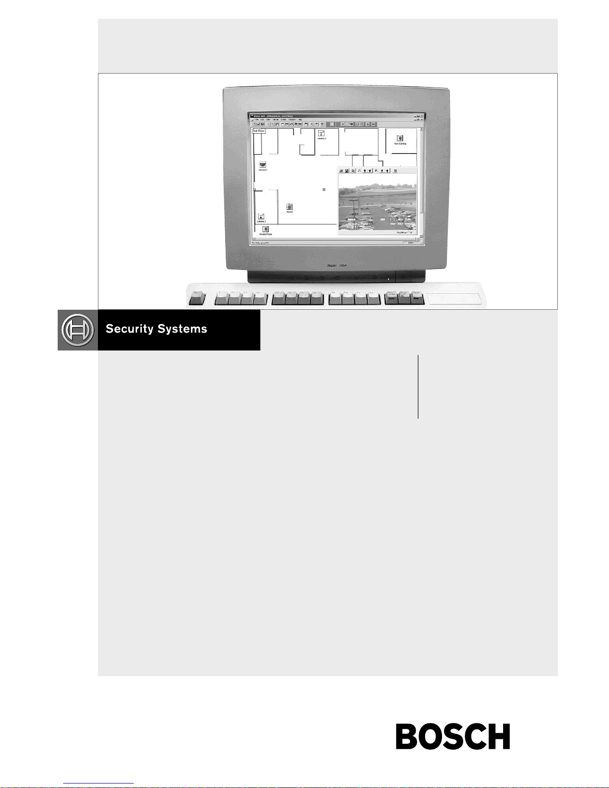
2.2 STARTING THE GUI MAP
APPLICATION
Open the appropriate GUI Map program group by
selecting the Applicable GUI Group icon (located in
the Start menu). The program group will open and
should appear similar to one of the groups in the
illustration shown below, depending on the server
software purchased.
Figure 1
Select the GUI program item from the Applicable
GUI group by double clicking on the GUI icon with
the left mouse button. Alternately, a shortcut for the
GUI can be created and used to start the application.
The shortcut can be set to automatically load a site
configuration file when the GUI is started. To do this,
first create a GUI shortcut using normal windows
techniques. Then right click on the shortcut icon, select
the Properties menu item and the shortcut tab. After the
map.exe executable filename in the target edit box,
add a space, then the name of the site configuration
file. Add the full path of the site configuration file in
the Start in edit box, then click OK. When the GUI

EN|9
Bosch Security Systems | 02 April 2004
LTC 8850 | Instruction Manual | GUI Map Application
is started, a Log-in dialog box will appear. See the
following illustration.
Figure 2 Log-in Dialog Box
When initially opening the GUI program, the
Installer User Name will appear. Enter the correct
password for the appropriate selection (see SECTION
2.1). A specific User Name is found by clicking on the
down arrow if one has been previously entered. If this
is the first time that the program is being run, the
Installer option should be selected. Highlight the user
name (privilege level) and click OK.
A window similar to the following screen (depending
on user profile entered) will appear when a log-in has
been confirmed. A toolbar is provided that contains
icons to simplify the menu utility functions such as
New Page, Open File, Save, etc. Resting the cursor
over these icons will cause a small information box to
automatically appear, describing the icon function. A
descriptive statement will also appear in the status line
at the bottom of the window.
The toolbar can be repositioned within the window.
Move the cursor over the toolbar on a gray area (but
not over an icon), click and hold down the left mouse
button, and drag the toolbar to the desired location. If
the toolbar is placed within the map page area, a
window border will surround it.
Figure 3 Empty GUI Main Window
2.3 MODIFYING A USER PROFILE
An installer can add, delete, or modify user names
from within the active users list; however, the last
installer’s name can NOT be deleted. Administrators
can alter all entries except those of an installer. The
user profile editing dialog box can be entered by
selecting the User Profile option from the File menu.
See the following illustration. This dialog box allows
Installers and Administrators to add, edit, and delete
Operators’ and other Administrators’ names. If an
illegal operation is attempted, a message box will
appear. To delete a user, highlight the line and select
the Delete User button.
Figure 4 User Profile Dialog Box
Figure 5 Message Box Specifying an Illegal Operation
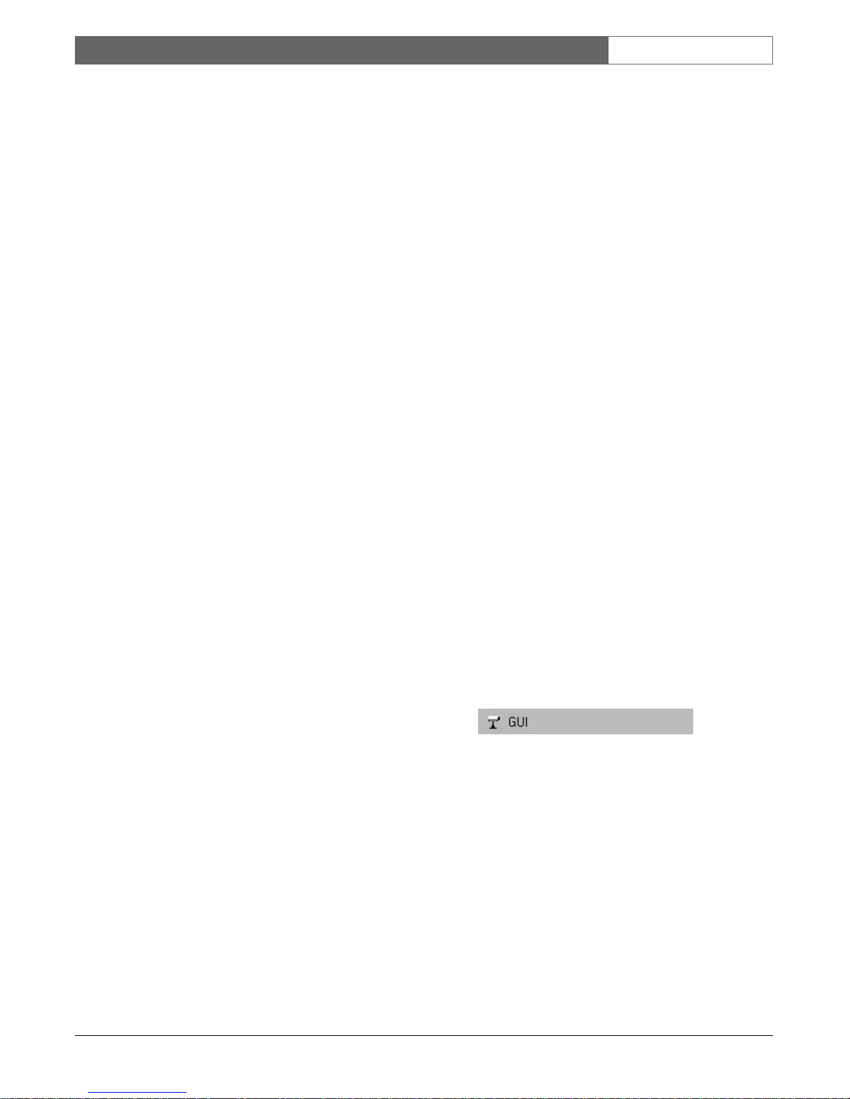
The following dialog box, User Properties, appears
when the Add User or Modify User button is selected
in the User Profile Window. This box is used to enter
the User Name, User Password, and the User’s Group
(Privilege level). In the following example, New User
is an Operator. An option to prohibit the Operator
from exiting the GUI is enabled by clicking the
checkbox. If the User is either an Installer or
Administrator, this checkbox will not be available.
EN|10
Bosch Security Systems | 02 April 2004
LTC 8850 | Instruction Manual | GUI Map Application
Figure 6 User Properties Dialog Box
To c hange a user’s password, select the Change
Password option from the File menu. The following
dialog box will appear. Enter the User’s Name, the
Old Password, the New Password, and a
confirmation password (Confirm New Password box).
Figure 7 Change Password Dialog Box
Installers and Administrators can add additional user
names to the log-in list, assigning a privilege level of
administrator or operator to each name. Installers can
also assign the privilege of Installer to other users.
2.4 STARTING A NEW SITE
CONFIGURATION FILE (MAP PAGE)
From the main window, installers can select either an
existing site configuration file or start a new one. If this
is the first time that the configuration program is being
run, the installer will need access to the CAD drawings
or architectural drawings representing the site being
monitored. Acceptable drawing formats which can be
imported into the GUI Map application are Bitmap
(.BMP), AutoCAD (.DXF), and HPGL (.HGL or .PLT)
formats. If there is a need for an additional drawing
format, consult your nearest Bosch Security Systems,
factory representative.
Select the File menu and choose the New option. A
blank map page will appear with the default name of
Page name 0001 (see the following illustration).
Figure 8 New Map Page Window
The window can be maximized by clicking on the
middle window control button at the top right of the
page window . Add the first site map by selecting
Import Map from within the Edit menu. The page
name may be changed by clicking on the page title
box, highlighting the text within, and typing in the
new name. The map page title box may also be
moved by clicking within the box until handles appear
(see the following illustration). Place the cursor on the
surrounding box until it becomes a cross. At this point,
click with the left mouse button and drag the box and
text to the desired location within the window.
Figure 9
2.5 EDITING AND ADDING MAP PAGES
NOTE: These activities can only be performed by an
installer and are not available to administrators or
operators.
Map pages can be added, modified, and/or deleted by
using the following commands located under the Edit
menu (see illustration following).
Figure 10 Edit Menu Selections
EN|11
Bosch Security Systems | 02 April 2004
LTC 8850 | Instruction Manual | GUI Map Application
2.5.1 Command Descriptions
Cut, Copy, Paste, and Select All: Commands all
perform in the same manner as most familiar
Windows‚ programs.
New Blank Page: Creates a new blank map page
within a new window of the map page area.
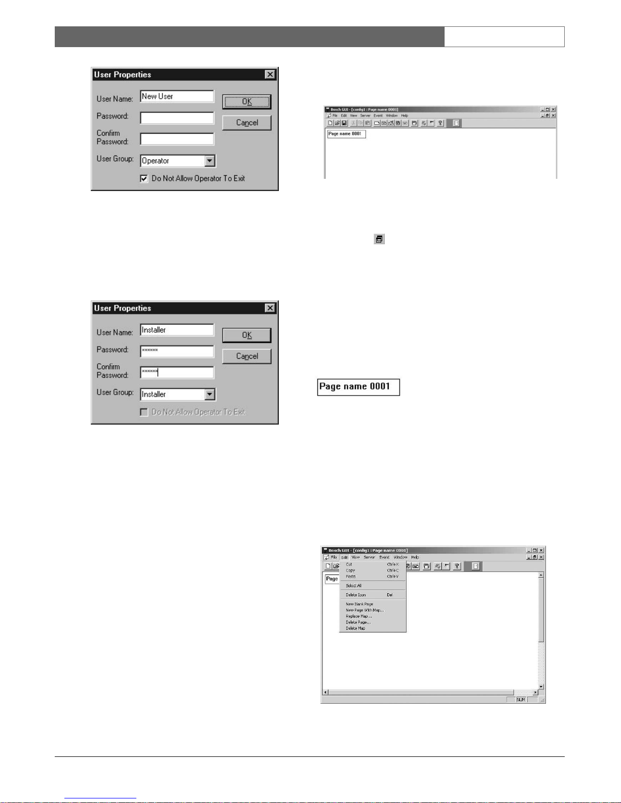
New Page with Map: This command invokes the
Import Map dialog box from which you can easily
browse through directories to find your map files.
When a map file of the correct format has been
chosen, the GUI will automatically load it into a new
page and display it in the new active window. Drawing
file formats which are supported are .BMP, .HGL,
.DXF, and .PLT.
Figure 11 Import Map Dialog Box
Import Map: Use this menu command to insert a map
into the current active window. This option is ONLY
available when the current active page does NOT
already contain a map. When the current page already
has an associated map, this command will be replaced
with the Replace Map option.
Replace Map: Use this command to replace a map
already associated with the active page. This command
is only available when the current active page already
contains a map. Upon selecting this option, the Import
Map dialog box will appear. If the current active page
does not contain a map, this option will be replaced by
the Import Map option.
Delete Page: Invokes a dialog box which allows the
user to select and delete any existing page in the active
configuration file. Note that all associated maps and
links to other pages will now become void. Linker
icons on other pages will have to be reconfigured.
Figure 12 Page Deletion Dialog Box
Delete Map: This option deletes the map from the
currently active page.
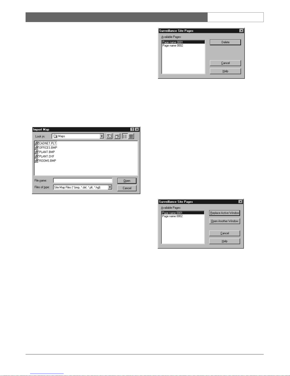
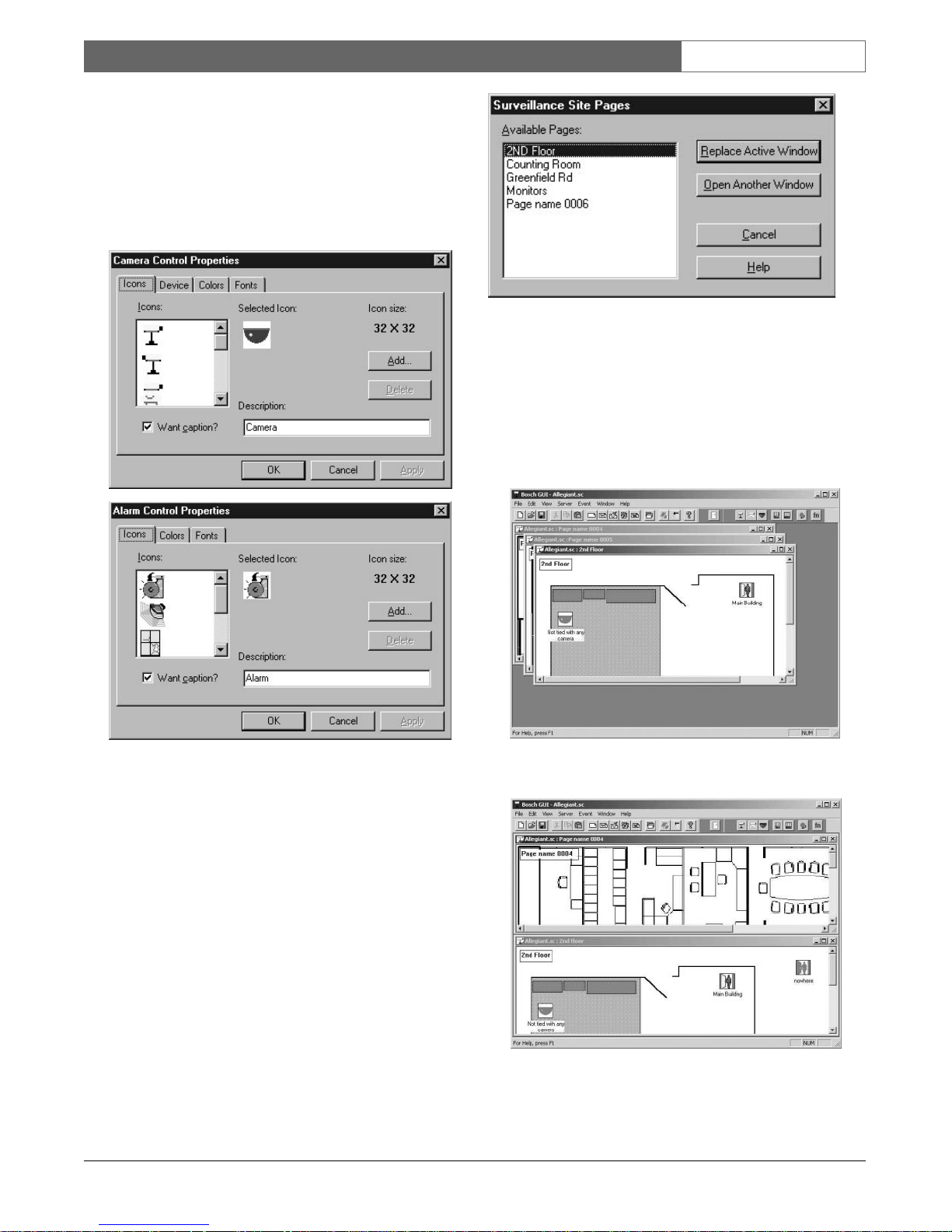
2.6 MOVING FROM ONE MAP PAGE
TO ANOTHER
To view additional map pages within the same
configuration file, select Page from the View menu or
click on the View Page icon in the toolbar. Highlight
the desired page from the dialog box and select
Replace Active Window. If you want to display the
page in its own window, select Open Another
Window. See illustration below. If the page is already
displayed in its own window and Open Another
Window is selected, the existing window will become
the topmost window (a new window will not be
created).
Figure 13 Replace Active/Open Another Window
Dialog Box
When this function is performed, the new page
replaces the existing page (there is only one map page
open within the map page area.
2.6.1 Linking Map Pages
The preferred method to maneuver from one map
page to another is to set up Linker Icons (represented
in the toolbar by a picture of a door) within each page
establishing a link to associated pages. See illustration.
To add a Linker Icon to the current active page/map,
perform the following:
EN|12
Bosch Security Systems | 02 April 2004
LTC 8850 | Instruction Manual | GUI Map Application
• Click on the linker icon with the left mouse button
and drag it into the map page The icon can be
placed in any location within the map page.
Initially, the linker icon will be labeled nowhere,
signifying that no link has been established to
another map page.
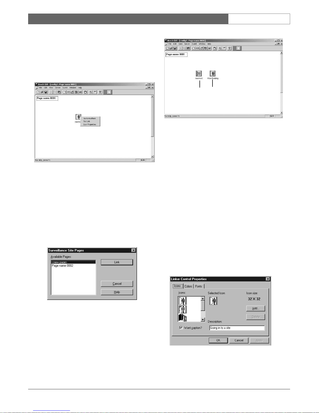
Figure 14 Linker Icon and Associated Menu
•To establish a link, right click with the mouse on
the placed Linker Icon; a Linker Icon menu box
will appear. See illustration.
•Select Set Link from the resulting menu. The list of
existing pages from within the present configuration
file will appear as in the dialog box shown below.
Select (highlight) the page with which you wish to
establish a link and click on the Link button.
Figure 15 Establish Link Dialog Box
The following illustration shows a page with two linker
icons, one without an established link and the other
with a link already established. There is no restriction
to the number of linking icons which you can establish
on a given page. The recommended method is to
establish a link from each page to all other pages to
which one wishes to maneuver.
Figure 16 Linked Page as viewed on screen
Double-clicking on the linker icon will bring the linked
page into view as the currently active page.
NOTE: The linker Icon will display the map page title
which you have established on the linked page.
Therefore, you can change the icon label to a title such
as Warehouse 1, Mezzanine Floor etc. by changing
the title box on the linked page.
2.6.2 Changing Linker Icon Properties
Clicking on the linker icon with the right mouse
button also displays the Properties option in the context
menu. Selecting Properties invokes the Linker Control
Properties dialog box, allowing for icon customization
(see illustration). After completing any changes, click
OK or press ENTER to put those changes into effect,
or click CANCE L to discard the changes. Clicking on
APPLY allows viewing changes without exiting the
Linker Control Properties dialog box.
Figure 17 Linker Control Properties Dialog Box
Linker Icon
Before Link
Has Been
Connected
Linker Icon
After Link
Has Been
Connected
EN|13
Bosch Security Systems | 02 April 2004
LTC 8850 | Instruction Manual | GUI Map Application
From within the Icon Control Properties dialog box,
you can remove the caption from the linker icon.
Additional information about the link which may be
useful to the installer may be entered into the
Description field. You can also change the linker icon
to one of the icons shown in the list or to one of your
choice by importing a bitmap (*.bmp) or a deviceindependent bitmap (*.dib) from available
drives/directories by selecting the Add option.
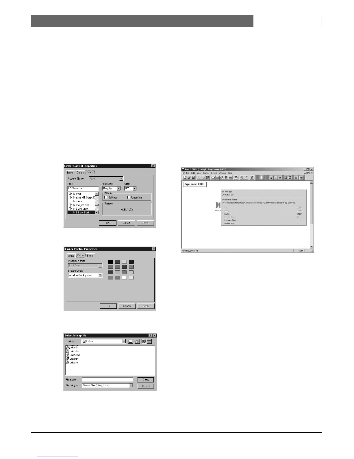
NOTE: Upgrading or reinstalling the GUI software
may remove custom icons from the icon list. Always
keep a copy of each .bmp or .dib file added so they
can be added again after a software upgrade or
reinstallation. The icon background color can also be
changed by using the Color tab and the title font can
be changed by selecting the Font tab (see illustrations).
Figure 18 Linker Icon Properties–Font Properties
Figure 19 Linker Icon Properties–Color Properties
Figure 20 Linker Icon Properties –Add Icon Selection
After the site configuration map pages and links have
been established, the next step is to add the icons
representing the cameras, monitors, and alarms of your
system. The following sections will discuss these
operations in more detail.
2.7 GENERAL MAP PAGE COMMANDS
Clicking anywhere in a map page other than on an
icon with the right mouse button will invoke a context
menu. Installers will receive a menu similar to the
following, providing them with direct access to Tool
Button area controls and many of the Edit menu
functions. Administrators and operators will receive a
context menu with only the Toolbar and Status Bar
functions available. See Functional Description of
Context Menu Commands.
Figure 21 Installer’s Page Context Menu
2.7.1 Functional Description of Map
Page Context Menu Commands
Tool Bar: Inserts or removes the Tool Bar from
the Tool Button area.
Status Bar: Inserts or removes the Status Bar from
the bottom of the current window.
Linker Control: Inserts or removes the Linker
Icon from the Tool Button area.
C:\Program Files\*\*.* Controls: Displays or
hides the applicable server seedbar from the Tool
button area. Allows the installer to turn off all but
the seedbar for the server from which he is seeding
icons. This makes it easier to seed icons when
multiple servers are loaded.
Cut: Cuts the applicable object from the page/map
and places it in Clipboard. Only available when an
object is highlighted.
EN|14
Bosch Security Systems | 02 April 2004
LTC 8850 | Instruction Manual | GUI Map Application
Copy: Copies the applicable object from the
page/map and places it in Clipboard. Only
available when an object is highlighted.
Paste: Pastes the contents of the clipboard to the
map page (location is arbitrarily chosen, after which
you can move the item to the desired location by
using the standard drag and drop technique).
Delete Icon: Deletes the highlighted icon.
Import Map: Displays the Import Map dialog box
for importing a map into the current active page.
Changes to the Replace Map option if a map is
already associated with the active page.
Replace Map: Displays the Import Map dialog
box for replacing the current map with a new user
selected map and inserting it into the currently
active page. When OK is chosen after a selection,
the old map is automatically replaced with the new
one. Only available when a map is associated with
the current active page.
Delete Map: Deletes the map associated with the
current active page.
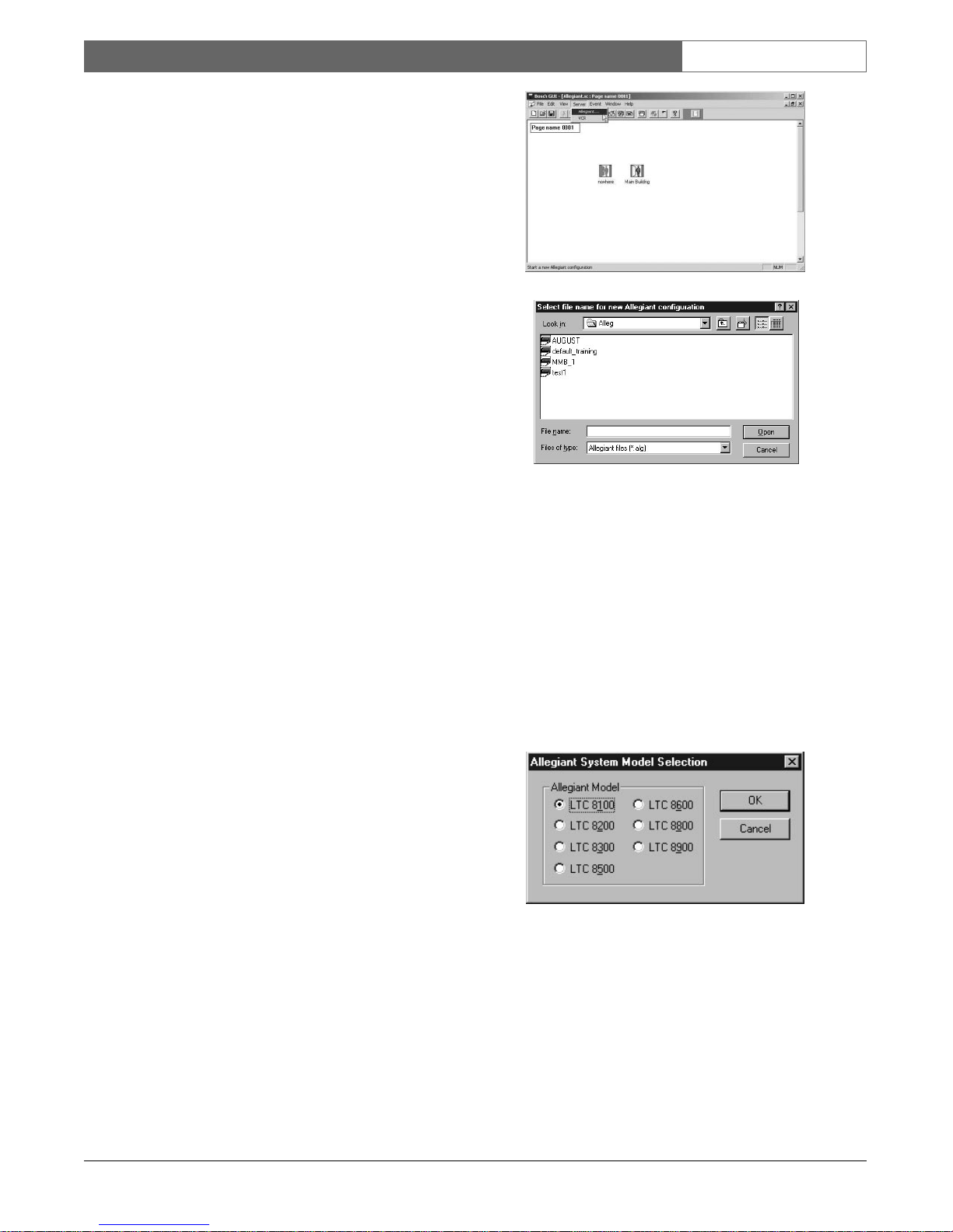
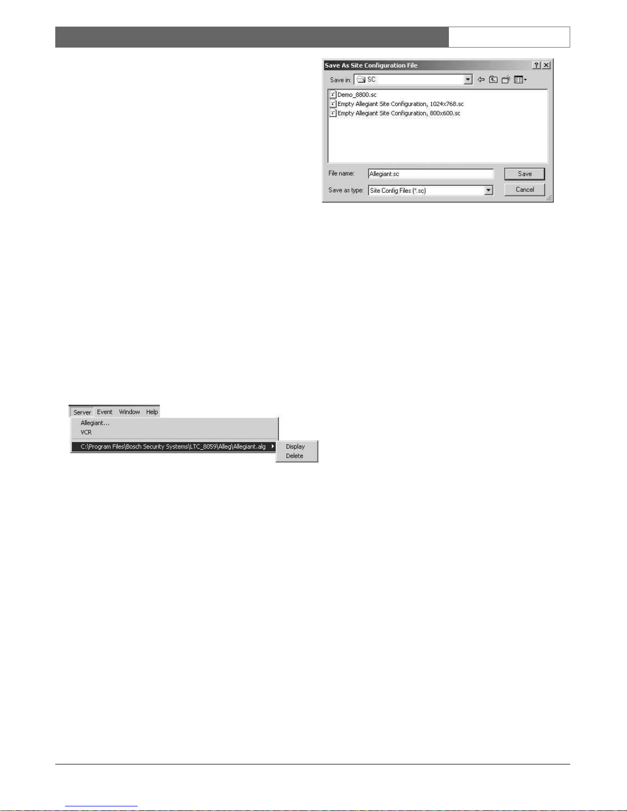
2.8 ADDING SERVER DEVICES
TO A MAP PAGE
To open server application, perform the following:
•From the Server menu, select the applicable server
application title. If configuring a new page, only the
Server applications will be available in this menu.
The list of available servers displayed in this menu
depends on the Bosch Security modules or product
servers installed on your system. If reconfiguring an
existing page, the configuration file titles will also
be available for the applications previously seeded.
See the following illustration (upper two menu
items are servers, lower two menu items are
existing configuration files). For some servers, when
you select the applicable server application title, a
new Configuration File dialog box will appear (see
illustration).
Figure 22 Server Menu
FIgure 23 Configuration File Dialog Box
• Enter the name for the new configuration file. The
file will be used to store the applicable server’s
configuration data. Existing configuration files can
be opened by selecting them from the file list. The
subdirectory used to store the configuration files
will depend upon the server and the directory
chosen during installation. The file extension for
the configuration file depends upon the server.
• The following dialog box will appear. Choose the
appropriate system model. Click OK or press
ENTER.
Figure 24 System Type Dialog Selection Box
EN|15
Bosch Security Systems | 02 April 2004
LTC 8850 | Instruction Manual | GUI Map Application
The system configuration filename entered will be
saved as part of the site configuration file. When a
previously configured site file is loaded into the GUI,
any other configuration files that were associated with
it will be automatically loaded. The icon seedbar for
the applicable server will be automatically loaded into
the GUI window toolbar area.
The Icon Seedbar facilitates the seeding of server
icons into the configuration file map pages. The
seedbar can be moved to any area of the window
including the page area. To move the icon seedbar,
click anywhere in the darker shaded gray area
surrounding the icon buttons while holding down the
left mouse button and dragging the seedbar until the
desired location for placement is reached.
The seeded icons will represent the actual field devices
to be connected to the server and hardware system.
Depending on the server applications which you have
available, you will now be able to seed configuration
icons such as cameras, monitors, or alarms into the site
configuration map pages.
Additional Servers can be added in the future if
multiple Allegiant Systems are connected. As other
servers are added, their corresponding seedbars will be
available for icon seeding.
When multiple servers of the same type are in your
system, the seedbar will contain a list of server
document names. Newly seeded icons will be
connected to the selected document in the list
Figure 25 Multiple Server Seedbar
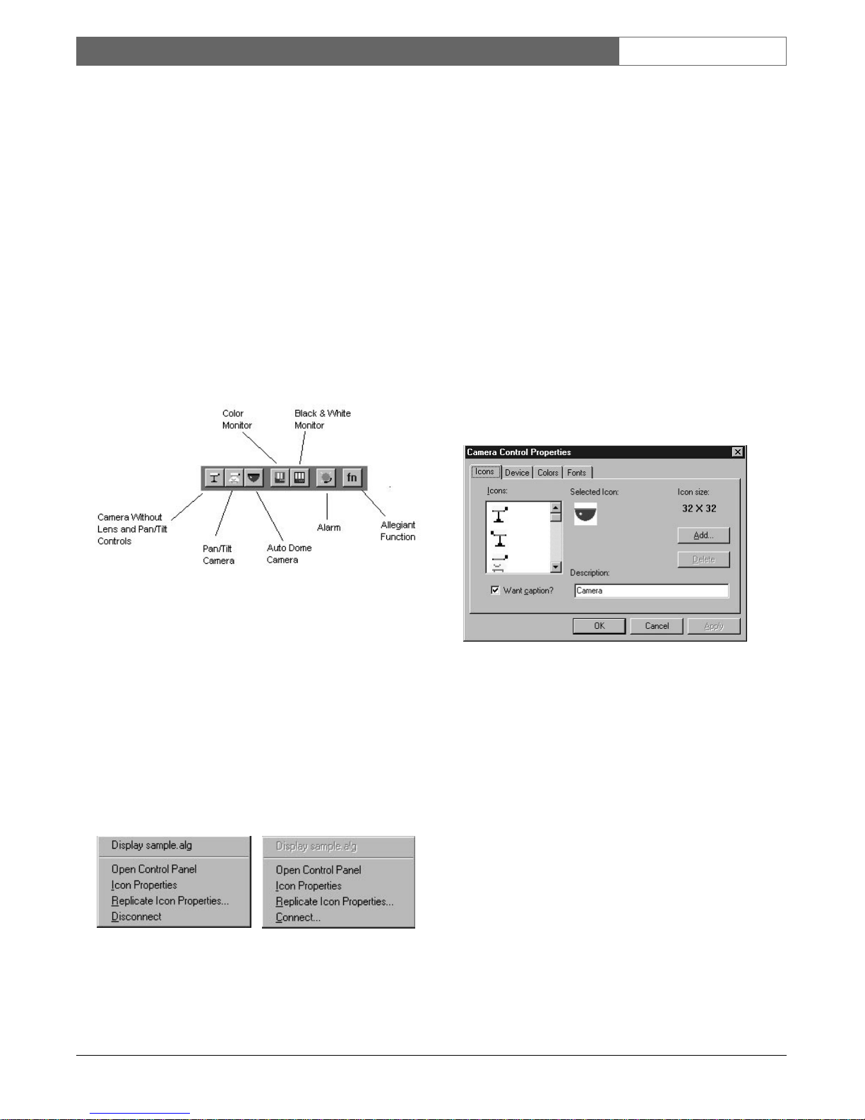
2.9 SEEDING ICONS
To place icons representing actual security devices into
a map page of the site configuration file, click and drag
the representative icon from the seedbar into the map
page (installer only). Device icons can then be
arranged within the map page to reflect actual physical
positioning of the field devices in a surveillance site.
Icons representing standard cameras, camera with a
pan/tilt, and AutoDome
®
cameras are available for
installers to seed into the system map pages. Note that
icons available on the seedbar vary depending on
server purchased. These icons can later be customized
with the use of an icon editor program (not included)
allowing the user to match the icons to their system’s
exact configuration. Icons representing all physical
devices installed in a system should be seeded into the
map, regardless of whether or not the devices (for
example an auxiliary alarm) are currently enabled.
2.10 DEVICE ICON PROPERTIES
NOTE: Icon Property menus vary depending upon the
type of server which you have installed, the type of
icon you are working with, and whether the icon has
been linked (connected).
Icon properties such as the background color and font
style can be changed by an installer. See the following
illustrations depicting an AutoDome camera context menu
on the Allegiant server package.
•To access the icon context menu, click on the icon
with the right mouse button.
Figure 26 Device Control Configuration Menu
•Select the Icon Properties option. Individual icon
properties will vary depending on the server
relating to the icon Seedbar; however, the color
(icon background) and font (icon title) options are
integral to all icon property menus. These two tab
options, once selected, allow the variation of these
individual functions. See the following illustrations.
EN|16
Bosch Security Systems | 02 April 2004
LTC 8850 | Instruction Manual | GUI Map Application
• When the device’s Control Properties dialog box
first appears, the initial tab will be labeled Icons.
This tab allows an installer to select from a variety
of predefined icons available with the particular
server application or to import an icon from
another source (also see Icon Properties under
Linker Icons).
Figure 27 Device Icon Properties
The Pan/Tilt function for a camera can be specified
from the Device tab of a Camera Control Properties
box, while the background color of the icon can be
changed from the Colors tab and the title font can be
changed from the Fonts tab.
2.11 WINDOW OPTIONS
Within the map page area, there are various methods
to manipulate map window configurations. Multiple
map windows may be displayed and placed in
different patterns within the map area.
To open multiple windows, go to View | Page | Open
Another Window.
Figure 28 Opening Multiple Windows
Methods for automatically arranging the Site
Configuration windows are included as options from
within the Window menu. Available options include
Cascade, Tile Horizontally, and Tile Vertically.
Following are example illustrations for these
configurations:
Figure 29 Cascading Map Window
Figure 30 Horizontally Tiled Map Windows
EN|17
Bosch Security Systems | 02 April 2004
LTC 8850 | Instruction Manual | GUI Map Application
Figure 31 Vertically Tiled Map Windows
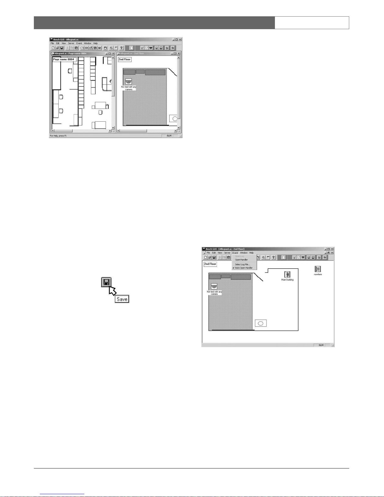
2.12 SAVING CONFIGURATION FILES
To save the site configuration from the GUI, select
either the Save or Save As option from the File menu.
If the file has not been saved previously, a file name
dialog box will appear. Any valid file name can be
used; however, the extension .sc (for Site
Configuration) is recommended. If an extension is not
provided, the default extension of .sc will be appended
automatically. You can also save the file by using the
toolbar Save button which has the picture of a disk on
front. Placing the cursor over any toolbar button will
momentarily give you a short description of the
button’s function (shown below).
Figure 32 Save Button
NOTE: The files saved include the map pages for
your site configuration (file extension designation *.sc)
and the name references of server configuration files
(e.g. *.Alg or *.vts).
2.13 EVENT HANDLER
The operator learns about alarm conditions through
various methods. If an alarm condition occurs from a
device which is in the current active map page, the
associated device icon will begin flashing and an
audible alarm will sound.
The Event Handler provides a method of informing
the operator when alarms occur in areas of the system
other than the map page which is presently open. It
also informs the operator what type of alarms are
occurring. The individual product servers determine
which events are handled by the Event Handler. If
multiple servers have icons loaded into the same
configuration file, alarms can be received from any of
the server configurations in the same Event Handler
window.
The Event Handler also provides a central point for
handling multiple simultaneous events from the
various system map pages without having to call up
every individual map page. The Event Handler
window may be accessed by selecting the Open
Handler option from the Event menu (see illustration
below). It may also be configured to open
automatically in the event of an alarm by selecting the
Auto Open Handler option (a check mark will appear
next to this option when the Event menu is selected). If
the window is already open but partially or fully
obscured, it will move to the top of the window order.
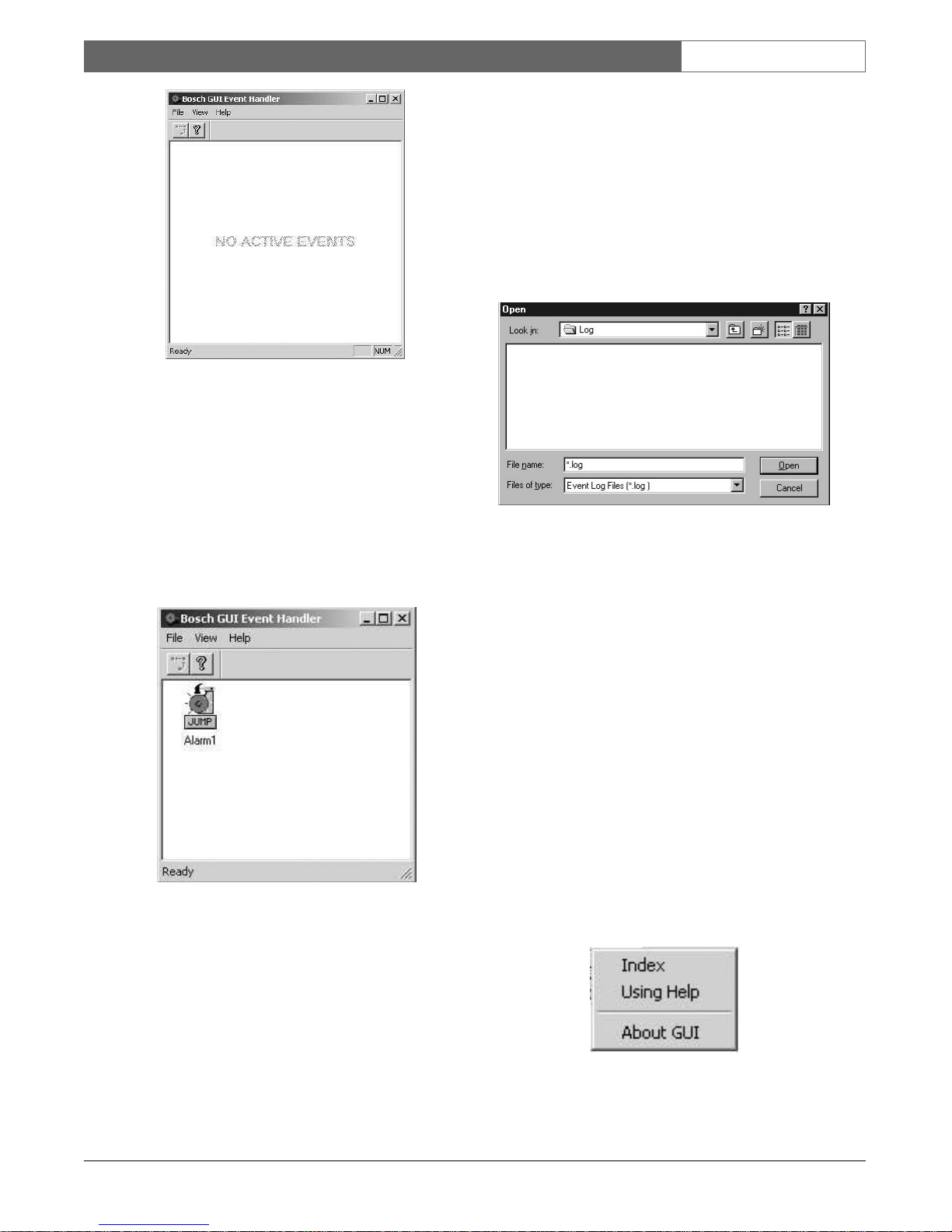
When all events are deactivated, the Event Handler
window will automatically close if Auto Open is
enabled, or it will stay open and display the message
NO ACTIVE EVENTS if the Auto Open function is
not enabled.
Figure 33 Event Menu with Auto Handler Open
Option Selected
When the Event Handler has no alarms present and it
is opened, a message will be seen in the Event Handler
window stating NO ACTIVE EVENTS. See the
following illustration.
EN|18
Bosch Security Systems | 02 April 2004
LTC 8850 | Instruction Manual | GUI Map Application
Figure 34 Event Handler with No Alarms Present
When an event occurs, an icon representing the event
is placed into the Event Handler window. The icon is
labeled with the title of the affected camera or alarm.
An audible alarm also goes off, informing the operator
of an alarm condition. The audible alarm can be shut
off by clicking on the Event Handler tool button. The
audible alarm will only shut off when the operator has
acknowledged ALL alarms which are present. See the
following illustrations.
Figure 35 Event Handler with Alarm Present
A hot button entitled Jump is also assigned to the icon
(see illustration). By clicking on the hot button beneath
the icon, the operator can automatically jump to the
map page which holds the alarming device icon. This
feature allows the operator to quickly identify the
location(s) in alarm. Any number of icons will be
simultaneously placed in the Event Handler if
multiple alarms occur simultaneously.
When the map page appears for the icon selected in
the Event Handler, the alarming device(s) icon(s) will
be flashing. By double clicking on an alarming icon,
you will open an alarm interface window which varies
depending on the server associated with the particular
icon.
NOTE: Jump icons will vary in appearance depending
upon the particular server from which the alarm is
initiated and the type of alarm received.
Figure 36 File selection box
Event activation and deactivation can be logged to disk
by selecting a file using the Select Log File option
from the Event menu. This will bring up a file selection
dialog box. If an existing filename is selected, the
options of appending to or overwriting the file will be
given. Selecting Append will cause new event entries
to be appended to the end of the file without
modifying existing data in the file. Selecting
Overwrite will cause the file to be emptied.
If an event log file has been specified, the file can be
opened for examination by selecting the Event | Open
Log File menu item or toolbar button. This will cause
the Windows‚ Notepad to open with the log file
loaded.
2.14 HELP
The Help menu provides three menu options (see
illustration).
Figure 37 Help menu
EN|19
Bosch Security Systems | 02 April 2004
LTC 8850 | Instruction Manual | GUI Map Application
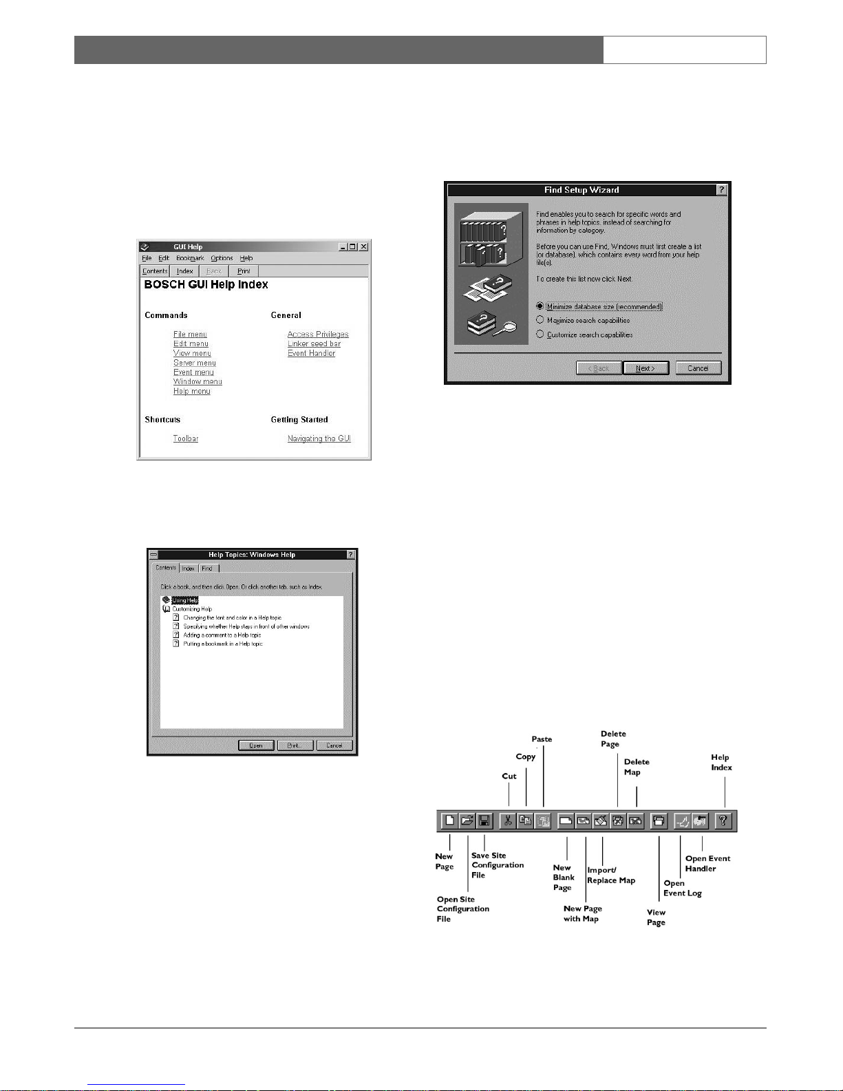
The Index option displays a listing of predetermined
GUI help topics. Clicking on any of the topics
displayed will provide help for that topic. Within any
of the topics, an underlined word or phrase (also
denoted by color scheme) indicates that further help is
available on the topic. Clicking on the underlined
word or phrase will cause the help for the selected
topic to be displayed.
Figure 38 Index Help Topics
The Using Help option displays the Help Topics
Windows Help Dialog Box.
Figure 39 Using Help Dialog Box
•Within the Using Help dialog box, you will find
specific file tabs pertaining to a Contents option, an
Index option, and a Find option.
• The Contents tab option displays a list of
predetermined GUI help topics.
• The Index tab option provides you with a search
engine to find predefined topics from within the
entire Contents help listing. Also available is a
scroll feature allowing you to scroll through the list
of available topics until you find the topic of
interest.
• The Find tab option allows you to search for help
on any topic
Figure 40 Using Help Option Find File Tab
The Help menu option About Help displays the GUI
copyright information (and version number).
2.15 THE TOOLBAR
The GUI Toolbar allows the user easy access to
several of the most used features available through
regular menu command options. These features
function in the same manner as the menu commands
previously discussed in this manual (for detailed
information on any item, see the appropriate section of
this manual). Following is an illustration of the GUI
Toolbar with available functions labeled (your screen
should appear similar). Anytime you place the cursor
over any of the tool buttons, a brief description of the
tool buttons function will momentarily appear on the
screen.
Figure 41 GUI Toolbar Functional Description
EN|20
Bosch Security Systems | 02 April 2004
LTC 8850 | Instruction Manual | GUI Map Application
2.16 RUNNING SERVER
CONFIGURATION PROGRAMS
It is recommended that you start the server programs
from the GUI map to maintain synchronization
between the two software systems. The Server menu
can be used to start new server configurations or jump
to open configurations. Prior to opening any server
configurations, this menu will provide selections for all
of the installed GUI product servers. The LTC 8850
GUI comes with the Allegiant Server and VCR Server
programs. Nomenclature designating the appropriate
server program will be displayed within the Server
menu, as well as any configuration files which have
been previously saved. If other Product Servers are
purchased in the future, entries for those servers will
also appear in the Server menu.
From the Server menu, select the appropriate server
name to open the server configuration of your choice.
Selecting a specific server will cause the appropriate
server window to appear with the specified filename in
focus. This allows the viewing or editing of the server
configuration tables (see configuring your system for
more detailed server information).
Figure 42 Server Menu Options
After selecting the appropriate server option, you may
be prompted to select a filename. To choose an
existing server configuration file, click on an existing
filename displayed, then click on the OK button or
press ENTER. If starting a new configuration file, it is
recommended that you use the filename extension
already depicted for the server you have selected. To
do this, press the Home key, placing the cursor at the
beginning of the File Name entry field. Now, press
Delete once to delete the asterisk (*). Type in the
appropriate filename and click on OK or press
ENTER.
Figure 43 Server Filename Selection Dialog Boxes
EN|21
Bosch Security Systems | 02 April 2004
LTC 8850 | Instruction Manual | Allegiant Server
3ALLEGIANT SERVER
3.1 ALLEGIANT SERVER ICONS
3.1.1 Introduction
The Allegiant server is used to configure and control
Allegiant systems. The server provides a seedbar to
installer level users when it is started by the GUI. The
seedbar is used to place icons into the map pages
which represent actual devices in the Allegiant system.
The majority of the functions discussed in the
following descriptions are only available to users with
installer or administrator level privileges.
3.1.2 Allegiant Server Seedbar
Figure 44 Allegiant Server Seedbar
Click and drag the representative icon from the
seedbar into the map page (installer only). Device
icons can then be assigned within the map to reflect
actual physical positioning of the field devices in a
surveillance site.
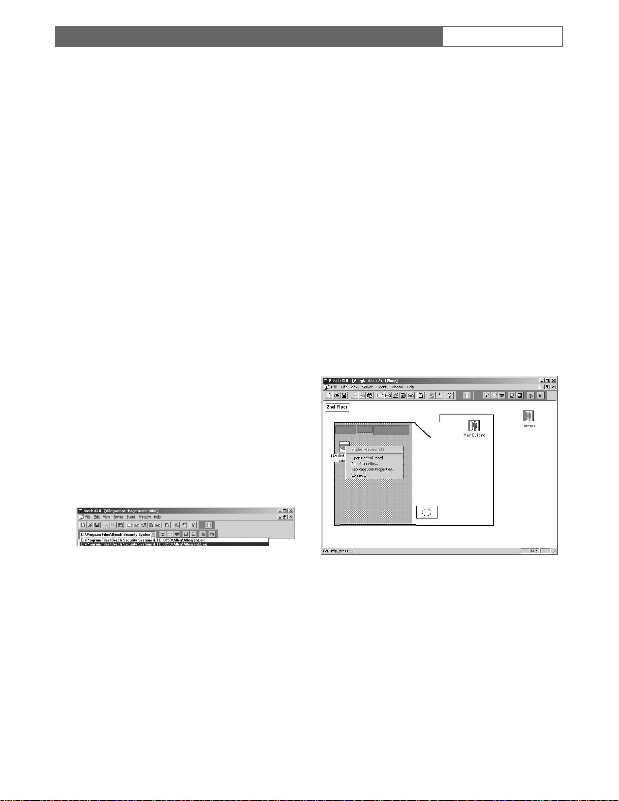
3.1.3 Allegiant Icon Right-click Menu
By clicking once on a camera, monitor, or alarm
icon with the right mouse button, the following rightclick menu appears (the Allegiant Function icon has a
different menu and will be discussed in a later section).
Figure 45 Camera, Monitor, Alarm Menu
3.1.3.1 Display Allegiant Server File Name
The top item in the right-click menu displays the name
of the Allegiant server file associated with the icon.
The command is enabled for selection when the icon
is connected to an Allegiant device. When this
command is selected, the Allegiant Server program
will appear displaying the associated device table. This
allows the user to easily verify or change device
configurations.
3.1.3.2 Open (Close) Control Panel
The icon’s control panel will open (close) when this
command is selected. This command changes to Close
Control Panel when the control panel is open.
3.1.3.3 Icon Properties
The Icon Properties dialog box will appear when this
command is selected.
Figure 46 Camera Icon Properties Dialog Box
This dialog box allows the user to change the icon, the
icon background color, some device characteristics,
and the font or font size used for the icon title
description. To change to a different functional tab,
simply click once on the appropriate tab with the left
mouse button.
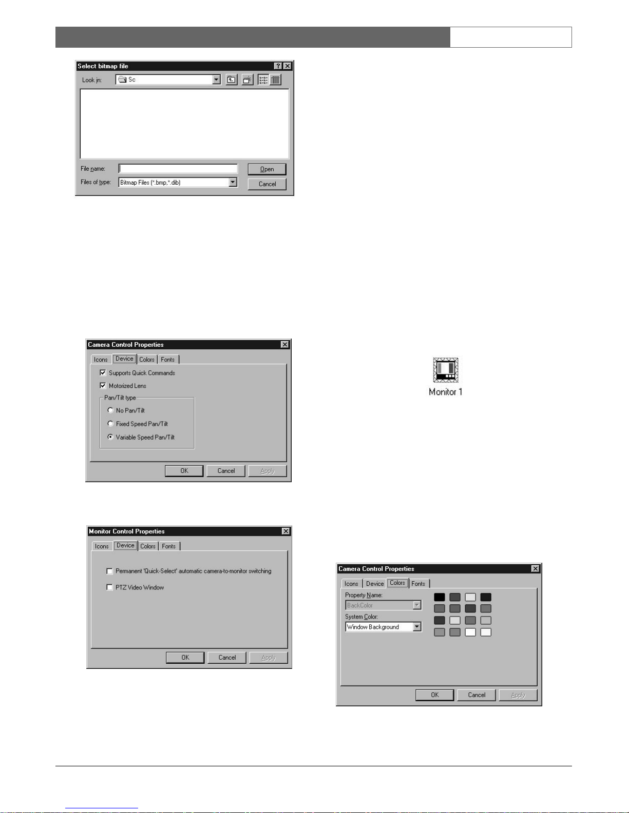
To c hange the device’s representative icon, select the
Icons tab. Select one of the icons provided with your
server by clicking on the icon of your choice and
clicking OK. You can also click Add, which allows you
to import a custom bitmap graphic. Clicking Add will
display the Select Bitmap File dialog box (see
illustration). From there you can browse available
directories for bitmaps. Single click on the bitmap file
name and then click Open to choose the bitmap.
EN|22
Bosch Security Systems | 02 April 2004
LTC 8850 | Instruction Manual | Allegiant Server
Figure 47 Select Bitmap File Dialog Box
NOTE: Upgrading or reinstalling the GUI software
may remove custom icons from the icon list. Always
keep a copy of each .bmp or .dib file added so they
can be added again after a software upgrade or
reinstallation.
Camera and Monitor icons have a Device that is used
to configure device specific information.
Figure 48 Camera Icon Device Tab
Figure 49 Monitor Icon Device Tab
For camera icons, select the available features which
match the characteristics of your device. Checking
Supports Quick Commands will make a button
appear in the camera’s expanded control panel called
Commands... . Clicking Commands... will display a
dialog box for entering Camera commands.
The Device Properties tab of a monitor icon has two
options that can be checked.
Permanent ‘Quick-Select’ automatic camera-tomonitor switching - Select this check box to make
this monitor always automatically switch to the next
camera selected in the map. For example if Monitor 1
is a ‘Quick-Select’ monitor and the user clicks on the
Camera 2 icon, Monitor 1 will switch to Camera 2.
Then, if the user clicks on the Camera 3 icon,
Monitor 1 will switch to Camera 3. Permanent ‘QuickSelect’ monitors will be outlined with blue cross hatch
to visually stand out from other monitor icons. There
can be any number of permanent Quick-Select
monitors at a time.
Figure 50 Permanent Quick-Select Monitor
PTZ Video Window - Select this check box to
associate the PTZ video window with this monitor. At
most, two monitor controls can have this selection
checked. A video board is required to use the PTZ
Video board (see the In Window PTZ SECTION).
To c hange the icon background color, click the Colors
tab. Click on a new color block from within the color
palette provided. The color selected will become
silhouetted, designating that is the active color.
Figure 51 Color Selection Tab
 Loading...