

Page 1
Video | LTC 8800 Series Allegiant Matrix/Control Systems - Modular
LTC 8800 Series Allegiant Matrix/Control
Systems - Modular
www.boschsecurity.com
u 256 Camera by 64 monitor switching
u Expandable to larger matrix sizes
The LTC 8800 Series Allegiant Video Switcher/Control
Systems combine both switching and computer
technology to provide powerful performance and
unique system features for the security user. Offering
full matrix switching capability, these systems can be
programmed to display the video from any camera on
any monitor, either manually or via independent
automatic switching sequences.
Functions
General Construction
The LTC 8800 Series provide versatile modular
construction, accommodating up to 256 camera
inputs, 64 monitor outputs, 32 keyboards, 1024 alarm
points, a computer interface port, and a logging
printer port.
Sequencing Capabilities
These systems can be programmed with up to 60
sequences which can be run independently of each
other in either a forward or reverse direction. Any of
the sequences can utilize the SalvoSwitching
capability, where any number of system monitors may
be selected to switch as a group. Using the optional
LTC 8059/00 master control software package,
u Modular construction
u Powerful alarm handling capabilities
u SalvoSwitching and SatelliteSwitch capability
sequences can be made to activate and deactivate
automatically based upon the time of day and the day
of the week.
Camera Control
The LTC 8800 Series support variable speed operation
and full programming access for AutoDome and
AutoDome Easy II Series cameras. In addition, on-site
receiver/drivers are available to provide operator
control of pan, tilt, zoom, pre-positions, auxiliaries,
auto-pan, and random scan functions when used with
conventional pan/tilt devices. An integral local test
function is also a standard feature.
The LTC 8800 Series include an impressive user-based
priority system and a series of programmable lockout
tables to limit operator access of remotely controlled
devices. Operators can restrict control from lower
priority operators either manually or automatically.
When enabled to operate automatically, a built-in timeout period is user programmable.
Bilinx® Capability
When combined with an LTC 8016 Allegiant Bilinx Data
Interface unit, these switcher/controllers support
operations using Bilinx communication. With Bilinx,
PTZ control is accomplished using a bidirectional
Page 2

2 | LTC 8800 Series Allegiant Matrix/Control Systems - Modular
communication protocol embedded in the video signal
of Bosch Dinion, AutoDome, and AutoDome Easy II
CCTV cameras. In addition, Bilinx uses the standard
video cable to transmit alarm and status messages
from the cameras, providing superior performance
without the need for separate data transmission
cables.
Alarm Capabilities
With the addition of the LTC 8540/00 Series alarm
interface accessory unit, an external contact closure or
logic level can be used to automatically activate any
camera to be displayed. Any monitor or group of
monitors can be set to display cameras under alarm
conditions. The base system contains three built-in
alarm response modes: basic, auto-build, and
sequence and display. In addition to these three
modes, the PC-based software packages now include
the ability to combine any or all the three standard
modes within the same system. Alarm video may be
selected to reset either manually or automatically. In
addition, a 16-character alarm title can be selected to
appear instead of the camera title during alarm
conditions.
System operation and programming is accomplished
using a full-function, ergonomically designed keyboard.
Up to 32 keyboards may be used in the system. Built-in
operator priority levels and the ability to restrict
certain operators from controlling designated
functions provide maximum flexibility.
Programming/Software Capabilities
The LTC 8800 Series include a black outlined 48
character on-screen display for time/date, camera
number, camera ID (16 characters), an icon to identify
controllable cameras, and monitor (12 characters) or
status information. A user selectable option provides
the ability to display a third line of on-screen text. This
third line can be configured to display up to 24
additional camera title characters (40 characters total)
or a 12-character monitor title.
The on-screen display is also user selectable to
operate in "6-digit Camera ID" mode. When enabled, 2digit "site numbers" are displayed in addition to the 4digit camera number. The 2-digit site number feature
is especially useful when groups of cameras are
located in separate buildings, floors, or other common
areas. Over 1000 characters are available when
programming camera ID and monitor titles.
Utilizing a standard Windows-based PC and the
optional LTC 8059/00 Master Control Software
package, enhanced programming and switching
features can be obtained. A user friendly spreadsheet
format provides the ability to enter camera titles,
operator names, or 64 timed events; change system
parameters; program camera sequences; install
lockouts; and access the advanced alarm handling
screens with speed and efficiency. The programmed
information may then be transferred into the Allegiant
system, stored on disk, or printed out directly from a
printer connected to the PC.
The LTC 8800 Series contain a logging printer output
port. This RS-232 serial interface can be connected to
the serial port of a PC to provide a permanent record
of system status showing the time and date of changes
such as incoming alarms, acknowledgment of alarms,
loading of sequences, user log-on to keyboard,
transfer of system tables and sequences, video loss
messages, and a power up reset message. In addition,
lists of the system's configuration tables and
sequences can be sent to the printer port.
The LTC 8800 system provides powerful macro
capabilities. The macros can be activated using
Allegiant Series system keyboards, system time event
functions, and alarm activations.
Expansion Capabilities
The LTC 8800 Series can serve as the master switcher
in a SatelliteSwitch configuration. This innovative
SatelliteSwitch feature enables a single LTC 8800
system to communicate with remotely located
“Satellite” systems. Any Allegiant system model can
serve as a remote Satellite switcher. This powerful
feature permits the design of a large distributed type
system with control at one central location and
individual control at the local sites. The main control
site can view/control local cameras plus cameras
located at any of the remotely distributed Satellite
sites. The Satellite sites can view/control only cameras
associated with their own site. When used in this type
of configuration, the main LTC 8800 system can
access up to 2048 cameras located anywhere in the
system.
Certifications and approvals
Electromagnetic
Compatibility (EMC)
Product Safety Complies with CE regulations, UL, CSA, EN,
Region Certification
Europe CE LTC 8601, LTC 8801, LTC 8802)
Complies with FCC Part 15, ICES-003, and
CE regulations. This product also complies
with EN 50121-4 railway application
standards. Refer to www.boschsecurity.com
website for link to applicable documents.
and IEC Standards
Page 3
5
10
1
1
2
3
7
4
5
8
9
6
1
2
3
4 5
6
7 8 9
0
Shot
MonProd
Clr
BOSCH
1
2
3
4 5
6
7 8 9
0
Shot
MonProd
Clr
BOSCH
1
2
3
4 5
6
7 8 9
0
Shot
MonProd
Clr
BOSCH
1
2
3
4 5
6
7 8 9
0
Shot
MonProd
Clr
BOSCH
1
2
3
4 5
6
7 8 9
0
Shot
MonProd
Clr
BOSCH
11
10
1
2
9
10
11
6
8
65
3
4
7
3
4
12
3 | LTC 8800 Series Allegiant Matrix/Control Systems - Modular
Installation/configuration notes
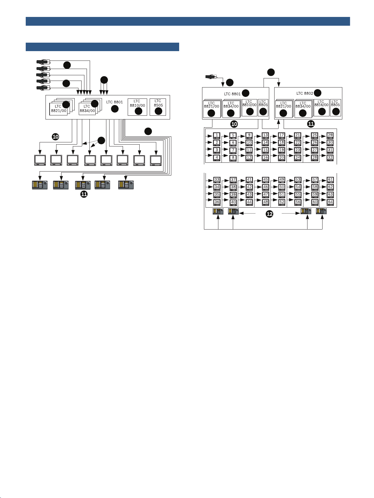
LTC 8800 Series Configuration Diagram
(256 Cameras by 32 Monitors)
1 Video Coax
2 256 Camera Inputs Maximum
3 Additional System Cameras
4 Input Cards (max. 8)
5 Output Cards (max. 8)
6 CPU Module
7 Power Supply Module
8 Series Main CPU Bay
9 3 m (10 ft) Interconnect Cable Supplied with Keyboard
1032 Monitor Output Capacity
1132 Full Matrix Monitor Outputs Maximum, 32 Full Function
Keyboards Maximum
LTC 8800 Series Dual-bay System (256 Cameras by 64
Monitors)
1 Coax Ribbon Jumper Cables (Supplied)
2 Up to 256 Cameras Total
3 8 x 32 Channel Input Cards (max. 8, each bay)
4 8 x 4 Channel Output Card (max. 8, each bay)
5 CPU Module
6 Power Supply Module
7 Data Receiver Module
8 Main CPU Bay
9 Monitor Expansion Bay
10Monitor Outputs 1 to 32
11Monitor Outputs 33 to 64
12Maximum of 32 Full-function Keyboards up to 1.5 km (5000 ft)
away Using Optional Remote Hookup Kit
Page 4

4
2
1
13
14
18
27
22
23
25
19
20
17
10
9
8
12
6
7
5
3
1 2
3
4 5
6
7 8
9
0
Shot
Mon
Prod
Clr
BOSCH
1 2
3
4 5
6
7 8
9
0
Shot
Mon
Prod
Clr
BOSCH
24
26
21
10
16
15
4 | LTC 8800 Series Allegiant Matrix/Control Systems - Modular
21Data Converter Units
22To any Local PTZ Camera Sites
23Code Merger Unit
24Alarm Interface Unit
25Local PTZ Control Data Line
26Alarm Interface Unit only Local Video on Local Monitors
27Keyboard Controls any of the Local Cameras on any of the Local
Monitors (Video and PTZ)
Allegiant Satellite Switching System
1 Monitor Outputs
2 Alarm Interface Unit
3 Pan/Tilt/Zoom and Satellite Control Data
4 Allegiant Main CPU Bay
5 Alarm Inputs May Activate Either Local or Satellite Video Main
Control Center's Monitor
6 Inputs Used for both Local and Trunk Lines
7 Local Camera Video
8 Signal Distribution Unit
9 To any Local PTZ Camera Sites
10Up to 1.5 km (5000 ft) using 1 mm2 (18 AWG) Shielded Twisted
Pair (Belden 8760 or Equivalent)
11Allegiant Keyboard Controls any Local or Remote Camera on any
Local Monitor (Video and PTZ)
12Multiple Video Trunk Lines from each Remote Satellite Location
13One Line to Each Remote Satellite System Location
14Pan/Tilt/Zoom and Satellite Control Data
Technical specifications
LTC 8800 Series System Specifications
Capacities
Video Inputs Standard: 256
Satellite configuration: 2048
Video Outputs 64
Keyboards 32
Alarm Inputs 1024
Receiver Drivers Standard: 256
Satellite configuration: 2048
Electrical
Input Voltage Level 0.5 Vp-p to 2 Vp-p
(composite negative sync)
Gain Unity ± 4% (75 Ohm terminated)
Pulse/Bar Ratios
1
Min. Nom. Max.
94% 98% 106%
2T Pulse K Factor
1
Min. Nom. Max.
0.2% 2.5%
Bar Amplitude (IRE)
1
Min. Nom. Max.
15Monitor Outputs Used as Video Trunk Lines to Main Control Site
Sync Amplitude (% Bar)
16Video Trunk Lines from other Satellite Locations
17Any Model Allegiant Main Bay
18Local Monitor
19Console Port Input
20Satellite Data Line
Field Time Waveform
Distortion
Line Time Waveform
Distortion
Short Time Waveform
Distortion
Long Time Waveform
Distortion
1
1
1
1
96 98 104
1
Min. Nom. Max.
36% 39% 44%
2% maximum
1% maximum
2% maximum
0.8% maximum
Page 5

5 | LTC 8800 Series Allegiant Matrix/Control Systems - Modular
Video Bandwidth (-3 dB)
Frequency Response
(± 0.5 dB)
2
Signal-to-Noise-Ratio
2
15 MHz
12 MHz
1
70 dB at 3.58 MHz
unified, unweighted minimum
Crosstalk (at 3.58 MHz) Input to input: -60 dB
Adjacent channel: -50 dB (typical)
Hum 60 dB below the composite
1 Vp-p video signal from 60 Hz to
6 MHz
Differential Gain
1
Min. Nom. Max.
--- 0.6% 2%
Differential Phase
1
Min. Nom. Max.
--- 0.6° 1.3°
Chrominance Luminance
1
Gain
Chrominance Luminance
1
Delay
Luminance Nonlinearity
Min. Nom. Max.
96% 100% 104%
Min. Nom. Max.
-33 ns +3 ns +33 ns
1
Min. Nom. Max.
--- 0.3% 4%
Switching Crosspoint matrix
DC Output 0.34 V
Transient Protection
(VIM Cards)
1 Meets EIA/TIA - 250C Medium Haul Standard for 256 cameras x 32 monitors.
2 One camera to one monitor.
350 W Peak Pulse Power
(tp = 8/20 µs
Environmental
Temperature
Operating 4°C to 50°C (40°F to 122°F)
Storage –40°C to 60°C (–40°F to 140°F)
Altitude 4500 m (15,000 ft)
Humidity 0% to 95% relative, non-condensing
Vibration 3 g swept sine wave, 15 Hz to 2000 Hz
Shock 50 g, 11 m/s, ½ sine wave
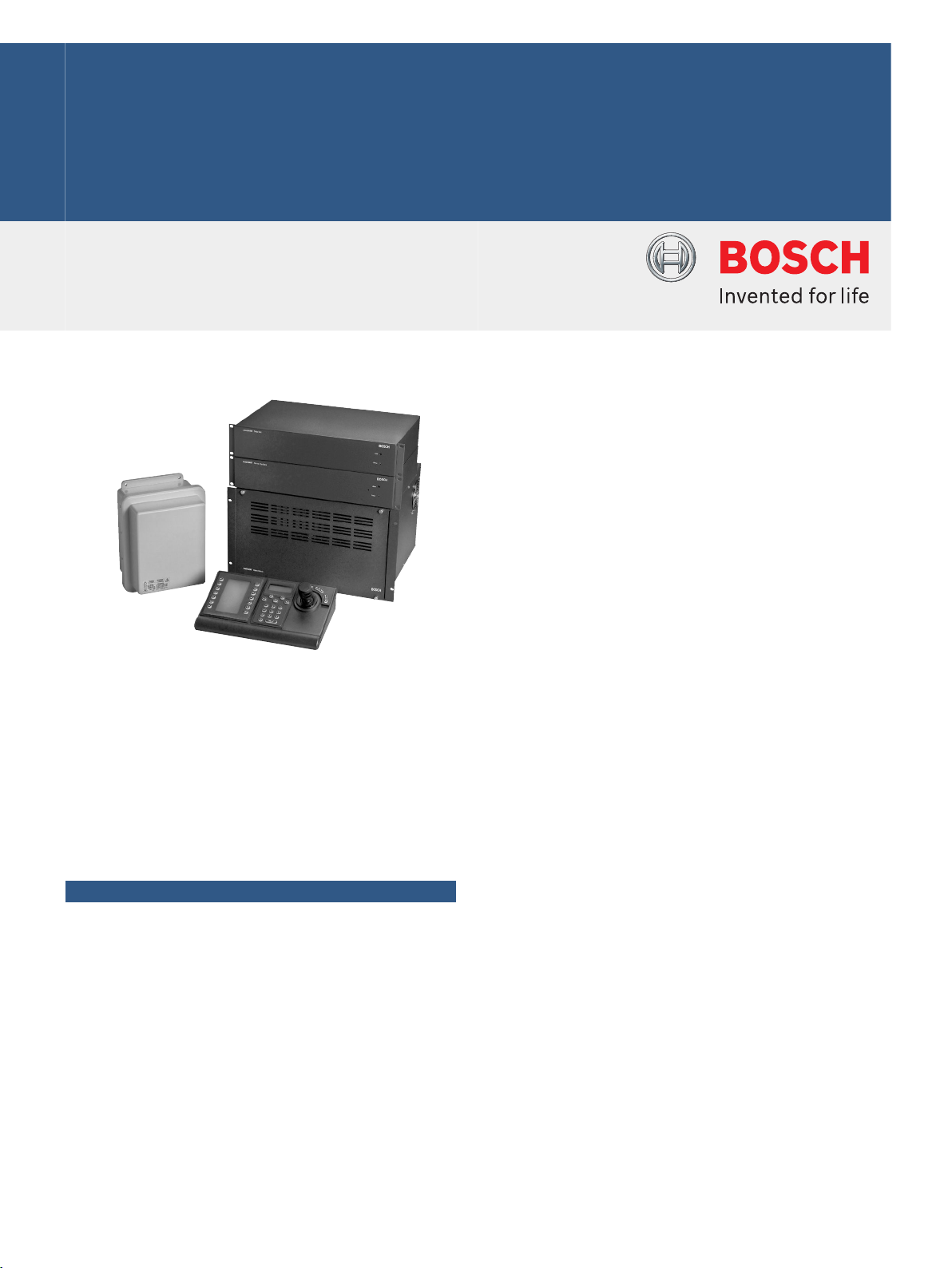
LTC 8801 Series Main CPU Bay
Includes equipment rack, LTC 8810/01 microprocessor module, and
LTC 8805 Series power supply.
Power
Model No. Rated Voltage Voltage Range Nominal
Power
3
LTC 8801/50 220-240 VAC,
198 to 264 200 W
50/60 Hz
3 Power at rated voltage fully loaded.
Connectors
Video Inputs:
1 to 96
Video Connections:
97 to 256
One (1) sync Input, and 32 monitor outputs
BNC
Ten (10), 34-pin ribbon connectors used in
conjunction with the LTC 8808/00 video
interconnect panel (purchased separately)
Looping Video
Connections:
1 to 256
Sixteen (16), 34-pin ribbon connectors used
in conjunction with the LTC°8808/00 video
interconnect panel (purchased separately)
External Accessory Interfaces
Console 9-pin D-type RS-232 port for external PC or
control interface (default = 19,200 baud)
Alarm 9-pin D-type RS-232 port for Allegiant alarm
accessory unit (default = 19,200 baud)
Printer 9-pin D-type RS-232 port for system logging
printer
default = 19,200 baud)
SDA 9-pin D-type TTL level, high-speed control data
output (Bi-Phase) for interface to Allegiant series
signal distribution units
(data clock rate = 31.25 kHz)
COMM Port 9-pin D-type RS-485 port for interbay
communication use (default = 125,000 baud)
COMM Port 9-pin D-type RS-485 port for external Allegiant
accessory use (default = 125,000 baud)
Keyboards Eight (8), 6-pin RS-485 ports for Allegiant
keyboard use (default = 9600 baud)
Equipment Rack (LTC 8801)
Size
(W x D x H)
EIA 48 cm (19 in.) rack
483 x 420 x 267 mm
(19 x 16.5 x 10.5 in.)
Weight 11.1 kg (24.5 lb)
Construction/Finish
Top and Bottom Steel
Front, Sides, and
Aluminum
Back
Finish Charcoal
Microprocessor Module (LTC 8810/01)
Size (D x H) 300 x 250 mm (11.8 x 9.8 in.)
Weight 0.5 kg (1.1 lb)
LTC 8801/60 120 VAC,
50/60 Hz
100 to 140 200 W
Page 6

6 | LTC 8800 Series Allegiant Matrix/Control Systems - Modular
Power Supply (LTC 8805/60–120 VAC, LTC 8805/50 –
220-240 VAC)
Size (W x D x H) 67 x 360 x 247 mm
(2.63 x 14.2 x 9.7 in.)
Weight 5.2 kg (11.5 lb)
Indicators One power On/Off, ten fuse alert, and one
external sync LED
LTC 8802 Series Monitor Expansion Bay
Includes equipment rack, LTC 8816/01 data receiver module, and
LTC 8805 Series power supply.
Power
Model No. Rated Voltage Voltage Range Nominal
LTC 8802/60 120 VAC,
100 to 140 200 W
Power
4
50/60 Hz
LTC 8802/50 220–240 VAC,
198 to 264 200 W
50/60 Hz
4. Power at rated voltage fully loaded.
Connectors
Video Inputs 1 to 96, and 32 monitor outputs BNC
Sync Input Not used
Video
Connections: 97
to 256
Looping Video
Connections:
1 to 256
Ten (10), 34-pin ribbon connectors used in
conjunction with the LTC 8808/00 video
interconnect panel (purchased separately)
Sixteen (16), 34-pin ribbon connectors used in
conjunction with the LTC 8808/00 video
interconnect panel
External Accessory Interfaces
Console 9-pin D-type connector, not used
Alarm 9-pin D-type connector, not used
Printer 9-pin D-type connector, not used
SDA 9-pin D-type connector, not used
COM Port 9-pin D-type connector RS-485 port for interbay
communication use
(default = 125,000 baud)
COM Port 9-pin D-type connector, not used
Keyboards Eight (8), 6-pin RS-485 ports for Allegiant
keyboard use (default = 125,000 baud)
Equipment Rack (LTC 8802 Series)
Size
(W x D x H)
EIA 48 cm (19 in.) rack,
483 x 420 x 267 mm
(19 x 16.5 x 10.5 in.)
Weight 11.1 kg (24.5 lb)
Construction/Finish
Top and Bottom Steel
Front, Sides, and
Aluminum
Back
Finish Charcoal
Data Receiver Module (LTC 8816/01)
Size
(W x D x H)
EIA 48 cm (19 in.) rack,
483 x 420 x 267 mm
(19 x 16.5 x 10.5 in.)
Weight 0.5 kg (1.1 lb)
Power Supply (LTC 8805/60–120 VAC,
LTC 8805/50220–240 VAC)
Size
(W x D x H)
67 x 360 x 247 mm
(2.63 x 14.2 x 9.7 in.)
Weight 5.2 kg (11 5 lb)
Indicators One power On/Off, ten fuse alert, and one
external sync LED
LTC 8821/00 Camera Input Module
Use up to eight per bay in main CPU bay. If monitor expansion bay is
being used, equip with duplicate number of modules.
Camera Inputs 32
Size (D x H) 300 x 250 mm (11.8 x 9.8 in.)
Weight 0.41 kg (0.9 lb)
LTC 8834/00 Monitor Output Module
Use up to eight per bay in main CPU or monitor expansion bay.
Monitor Outputs 4
Size (D x H) 300 x 250 mm (11.8 x 9.8 in.)
Weight 0.41 kg (0.9 lb)
LTC 8808/00 Video Interconnect Panel
NOTE: Use of the LTC 8808/00 assemblies are required for system
video inputs 97 to 256 and must be purchased separately. The
LTC 8808/00 assembly contains an interconnect panel which is used to
convert 32 BNC connectors into two 16- channel ribbon cable
connectors. The two, 16-conductor ribbon cables (LTC 8809/00),
designed especially for use with video signals, and are then used to
interconnect the video between the panel and the LTC 8800 Series
system. In addition to being used for video inputs 97 to 256, the
LTC 8808/00 assembly can also be ordered as an option to provide
looping output capability. For looping purposes, one LTC 8808/00
(includes one panel and two ribbon cables) is required for each group of
32 cameras.
The following table can be used to determine the number of
LTC 8808/00 assemblies that must be purchased:
Number of
System
Cameras
Number of LTC 8808
Assemblies Required
for Camera Input
Connections Only
Number of LTC 8808
Required for Inputs
and Looping Video
Outputs
Page 7

7 | LTC 8800 Series Allegiant Matrix/Control Systems - Modular
1 to 32 None 1
33 to 64 None 2
65 to 96 None 3
97 to 128 1 5
129 to 160 2 7
161 to 196 3 9
197 to 224 4 11
225 to 256 5 13
Finish Charcoal
Size
(W x D x H)
Weight
Panel 0.54 kg (1.2 lb)
Ribbon Cables
(2)
Allegiant Accessories
The LTC 8800 Series accessory products provide many optional
features to the base Allegiant switching systems. Accessory products
include keyboard extension kits, Allegiant Bilinx Data Interface unit,
receiver/driver units, switcher/followers, code merger units, the video
ribbon cable and key- board expansion units. All accessory products are
designed to be installer-friendly and compatible throughout Allegiant
series systems. See the Allegiant Accessories datasheet.
EIA 48 cm (19 in.) rack,
483 x 42 x 44 mm (19 x 1.65 x 1.75 in.)
0.3 kg (0.7 lb)
Ordering information
LTC 8801/50 Allegiant Matrix Switcher
Includes equipment rack, LTC 8810/01 microprocessor
module and LTC 8805 Series power supply;
220-240 VAC, 50/60 Hz
Order number LTC 8801/50
LTC 8834/00 Video Output Module
for LTC 8600 and LTC 8800, 4 video outputs per card
Order number LTC 8834/00
Accessories
LTC 8810/00 Spare CPU Molule
for LTC 8801/00 bay
Order number LTC 8810/00
LTC 8805/50 Spare Power Supply
for LTC 8601/50 bay, 220-240 VAC, 50 Hz
Order number LTC 8805/50
LTC 8805/60 Spare Power Supply
for LTC 8601/60 bay, 120 VAC, 60 Hz
Order number LTC 8805/60
LTC 8810/01 Spare CPU Module
for LTC 8801 bay
Order number LTC 8810/01
LTC 8816/00 Data Receiver Module
for LTC 8802/00, 0.5 kg (1.1 lb)
Order number LTC 8816/00
LTC 8816/01 Data Receiver Module
REP data RX module, LTC 8802 Series
Order number LTC 8816/01
Software Options
SFT-VASA Hybrid IP - Analog/Matrix Video over IP Integration Software
Order number SFT-VASA
LTC 8059/00 Allegiant Master Control Software
Order number LTC 8059/00
LTC 8850/00 GUI Allegiant Single User Software Package
Order number LTC 8850/00
LTC 8801/60 Allegiant Matrix Switcher
Includes equipment rack, LTC 8810/01 microprocessor
module and LTC 8805 Series power supply; 120 VAC,
50/60 Hz
Order number LTC 8801/60
LTC 8802/50 Monitor Expansion Bay
Includes equipment rack, LTC 8816/01 data receiver
module and LTC 8805 Series power supply; 220–
240 VAC, 50/60 Hz
Order number LTC 8802/50
LTC 8802/60 Monitor Expansion Bay
Includes equipment rack, LTC 8816/01 data receiver
module and LTC 8805 Series power supply; 120 VAC,
50/60 Hz
Order number LTC 8802/60
LTC 8821/00 Video Input Module
for LTC 8800, 32 video inputs per card
Order number LTC 8821/00
SFT‑INTSRV Integration Server Software
Allegiant integration software package
Order number SFT-INTSRV
Page 8

8 | LTC 8800 Series Allegiant Matrix/Control Systems - Modular
Represented by:
Americas: Europe, Middle East, Africa: Asia-Pacific: China: America Latina:
Bosch Security Systems, Inc.
130 Perinton Parkway
Fairport, New York, 14450, USA
Phone: +1 800 289 0096
Fax: +1 585 223 9180
security.sales@us.bosch.com
www.boschsecurity.us
Bosch Security Systems B.V.
P.O. Box 80002
5617 BA Eindhoven, The Netherlands
Phone: + 31 40 2577 284
Fax: +31 40 2577 330
emea.securitysystems@bosch.com
www.boschsecurity.com
Robert Bosch (SEA) Pte Ltd, Security
Systems
11 Bishan Street 21
Singapore 573943
Phone: +65 6571 2808
Fax: +65 6571 2699
apr.securitysystems@bosch.com
www.boschsecurity.asia
Bosch (Shanghai) Security Systems Ltd.
201 Building, No. 333 Fuquan Road
North IBP
Changning District, Shanghai
200335 China
Phone +86 21 22181111
Fax: +86 21 22182398
www.boschsecurity.com.cn
Robert Bosch Ltda Security Systems Division
Via Anhanguera, Km 98
CEP 13065-900
Campinas, Sao Paulo, Brazil
Phone: +55 19 2103 2860
Fax: +55 19 2103 2862
latam.boschsecurity@bosch.com
www.boschsecurity.com
© Bosch Security Systems 2013 | Data subject to change without notice
2366345099 | en, V1, 04. Oct 2013
 Loading...