

Bosch LTC 2600 Instruction Manual
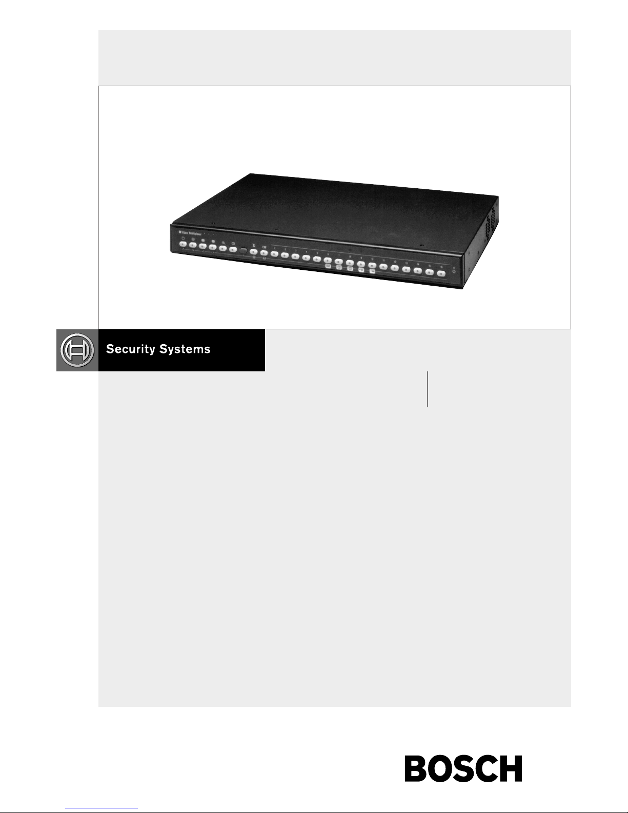
System4 Video Controllers LTC 2600 Series
Instruction Manual
EN Command Console
Language

LTC 2600 Series | Instruction Manual | Important Safeguards
EN
|
2
Bosch Security Systems | July 12, 2004
Important Safeguards
1. Read, Follow, and Retain Instructions - All safety
and operating instructions should be read and
followed before operating the unit. Retain instructions
for future reference.
2. Heed Warnings - Adhere to all warnings on the unit
and in the operating instructions.
3. Attachments - Attachments not recommended by the
product manufacturer should not be used, as they
may cause hazards.
4. Installation Cautions - Do not place this unit on an
unstable stand, tripod, bracket, or mount. The unit
may fall, causing serious injury to a person and
serious damage to the unit. Use only manufacturerrecommended accessories, or those sold with the
product. Mount the unit per the manufacturer's
instructions. Appliance and cart combination should
be moved with care. Quick stops, excessive force, or
uneven surfaces may cause the appliance and cart
combination to overturn.
5. Cleaning - Unplug the unit from the outlet before
cleaning. Follow any instructions provided with the
unit. Generally, using a damp cloth for cleaning is
sufficient. Do not use liquid cleaners or aerosol
cleaners.
6. Servicing - Do not attempt to service this unit
yourself. Opening or removing covers may expose
you to dangerous voltage or other hazards. Refer all
servicing to qualified service personnel.
7. Damage Requiring Service - Unplug the unit from
the main AC power source and refer servicing to
qualified service personnel under the following
conditions:
•When the power supply cord or plug is damaged.
• If liquid has been spilled or an object has fallen
into the unit.
• If the unit has been exposed to water and/or
inclement weather (rain, snow, etc.).
• If the unit does not operate normally, when
following the operating instructions. Adjust only
those controls specified in the operating
instructions. Improper adjustment of other controls
may result in damage, and require extensive work
by a qualified technician to restore the unit to
normal operation.
• If the unit has been dropped or the cabinet
damaged.
• If the unit exhibits a distinct change in
performance, this indicates that service is needed.
8. Replacement Parts - When replacement parts are
required, the service technician should use
replacement parts specified by the manufacturer or
that have the same characteristics as the original part.
Unauthorized substitutions may result in fire,
electrical shock or other hazards.
9. Safety Check - Upon completion of servicing or
repairs to the unit, ask the service technician to
perform safety checks to ensure proper operating
condition.
10. Power Sources - Operate the unit only from the type
of power source indicated on the label. If unsure of
the type of power supply to use, contact your dealer
or local power company.
•For units intended to operate from battery power,
refer to the operating instructions.
•For units intended to operate with External Power
Supplies, use only the recommended approved
power supplies.
•For units intended to operate with a limited power
source, this power source must comply with
EN60950. Substitutions may damage the unit or
cause fire or shock.
•For units intended to operate at 24VAC, normal
input voltage is 24VAC. Voltage applied to the
unit's power input should not exceed 30VAC.
User-supplied wiring, from the 24VAC supply to
unit, must be in compliance with electrical codes
(Class 2 power levels). Do not ground the 24VAC
supply at the terminals or at the unit's power
supply terminals.
11. Coax Grounding - If an outside cable system is
connected to the unit, ensure that the cable system is
grounded. U.S.A. models only - Section 810 of the
National Electrical Code, ANSI/NFPA No.70,
provides information regarding proper grounding of
the mount and supporting structure, grounding of the
coax to a discharge unit, size of grounding
conductors, location of discharge unit, connection to
grounding electrodes, and requirements for the
grounding electrode.
12. Grounding or Polarization - This unit may be
equipped with a polarized alternating current line
plug (a plug with one blade wider than the other).
This safety feature allows the plug to fit into the
power outlet in only one way. If unable to insert the
plug fully into the outlet, try reversing the plug. If the
plug still fails to fit, contact an electrician to arrange
replacement of the obsolete outlet. Do not defeat the
safety purpose of the polarized plug.
Alternately, this unit may be equipped with a
3-wire grounding plug (a plug with a third pin, for
grounding). This safety feature allows the plug to fit
into a grounding power outlet only. If unable to insert
the plug into the outlet, contact an electrician to
arrange replacement of the obsolete outlet. Do not
defeat the safety purpose of the grounding plug.
13. Lightning - For added protection during a lightning
storm, or when this unit is left unattended and unused
for long periods of time, unplug the unit from the
wall outlet and disconnect the cable system. This will
prevent damage to the unit due to lightning and
power line surges.
LTC 2600 Series | Instruction Manual | Safety Precautions
EN
|
3
Bosch Security Systems | July 12, 2004
For Indoor Product
1. Water and Moisture - Do not use this unit near
water - for example, in a wet basement, in an
unprotected outdoor installation, or in any area
classified as a wet location.
2. Object and Liquid Entry - Never push objects of
any kind into this unit through openings, as they
may touch dangerous voltage points or short out
parts that could result in a fire or electrical shock.
Never spill liquid of any kind on the unit.
3. Power Cord and Power Cord Protection - For
units intended to operate with 230VAC, 50Hz,
the input and output power cord must comply
with the latest versions of IEC Publication 227 or
IEC Publication 245.
Power supply cords should be routed so they are
not likely to be walked on or pinched. Pay
particular attention to location of cords and plugs,
convenience receptacles, and the point of exit
from the appliance.
4. Overloading - Do not overload outlets and
extension cords; this can result in a risk of fire or
electrical shock.
For Outdoor Product
Power Lines - An outdoor system should not be
located in the vicinity of overhead power lines,
electric lights, or power circuits, or where it may
contact such power lines or circuits. When
installing an outdoor system, extreme care should
be taken to keep from touching power lines or
circuits, as this contact might be fatal. U.S.A.
models only - refer to the National Electrical
Code Article 820 regarding installation of CATV
systems.
For Rack-mount Product
1. Ventilation - This unit should not be placed in a
built-in installation or rack, unless proper
ventilation is provided, or the manufacturer’s
instructions have been adhered to. The
equipment must not exceed its maximum
operating temperature requirements.
2. Mechanical Loading - Mounting of the
equipment in a rack shall be such that a
hazardous condition is not achieved due to
uneven mechanical loading.
Safety Precautions
Attention: Installation should be performed by
qualified service personnel only in accordance
with the National Electrical Code or applicable
local codes.
Power Disconnect. Units with or without ONOFF switches have power supplied to the unit
whenever the power cord is inserted into the
power source; however, the unit is operational
only when the ON-OFF switch is in the ON
position. The power cord is the main power
disconnect for all units.
CAUTION: TO REDUCE THE RISK OF
ELECTRIC SHOCK, DO NOT REMOVE COVER
(OR BACK). NO USER SERVICEABLE PARTS
INSIDE. REFER SERVICING TO QUALIFIED
SERVICE PERSONNEL.
This symbol indicates the presence of
uninsulated “dangerous voltage” within the
product’s enclosure. This may constitute a
risk of electric shock.
The user should consult the operating and
maintenance (servicing) instructions in the
literature accompanying the appliance.
LTC 2600 Series | Instruction Manual | FCC & ICES Information
EN
|
4
Bosch Security Systems | July 12, 2004
Sécurité
Attention : l'installation doit exclusivement être réalisée par du
personnel qualifié, conformément au code national d'électricité
américain (NEC) ou au code d'électricité local en vigueur.
Coupure de l'alimentation. Qu'ils soient pourvus ou non d'un
commutateur ON/OFF, tous les appareils reçoivent de l'énergie une
fois le cordon branché sur la source d'alimentation. Toutefois,
l'appareil ne fonctionne réellement que lorsque
le commutateur est réglé sur ON. Le débranchement du cordon
d'alimentation permet de couper l'alimentation des appareils.
AT TENTION : POUR ÉVITER TOUT RISQUE D'ÉLECTROCUTION,
N'ESSAYEZ PAS DE RETIRER LE CAPOT (OU LE PANNEAU
ARRIÈRE). CET APPAREIL NE CONTIENT AUCUN COMPOSANT
SUSCEPTIBLE D'ÊTRE RÉPARÉ PAR L'UTILISATEUR. CONFIEZ
LA RÉPARATION DE L'APPAREIL À DU PERSONNEL QUALIFIÉ.
Ce symbole signale que le produit renferme une « tension
potentiellement dangereuse » non isolée susceptible de
provoquer une électrocution.
Ce symbole invite l'utilisateur à consulter les instructions
d'utilisation et d'entretien (dépannage) reprises dans la
documentation qui accompagne l'appareil.
Sicherheitshinweise
Achtung! Die Installation sollte nur von qualifiziertem
Kundendienstpersonal gemäß jeweils zutreffender
Elektrovorschriften ausgeführt werden.
Unterbrechung des Netzanschlusses. Geräte mit oder ohne
Netzschalter haben Spannung am Gerät anliegen, sobald der
Netzstecker in die Steckdose gesteckt wird. Das Gerät ist jedoch
nur betriebsbereit, wenn der Netzschalter (EIN/AUS) auf EIN
steht. Wenn das Netzkabel aus der Steckdose gezogen wird, ist
die Spannungszuführung zum Gerät vollkommen unterbrochen.
VORSICHT: UM EINEN ELEKTRISCHEN SCHLAG ZU
VERMEIDEN, IST DIE ABDECKUNG (ODER RÜCKSEITE) NICHT
ZU ENTFERNEN. ES BEFINDEN SICH KEINE TEILE IN DIESEM
BEREICH, DIE VOM BENUTZER GEWARTET WERDEN
KÖNNEN. LASSEN SIE WARTUNGSARBEITEN NUR VON
QUALIFIZIERTEM WARTUNGSPERSONAL AUSFÜHREN.
Das Symbol macht auf nicht isolierte „gefährliche Spannung"
im Gehäuse aufmerksam. Dies kann zu einem elektrischen
Schlag führen.
Der Benutzer sollte sich ausführlich über Anweisungen für
die Bedienung und Instandhaltung (Wartung) in den
begleitenden Unterlagen informieren.
Precauciones de Seguridad
Atención: la instalación la debe realizar únicamente personal
cualificado de conformidad con el National Electric Code o las
normas aplicables en su país.
Desconexión de la alimentación. Las unidades con o sin
interruptores de encendido/apagado reciben alimentación
eléctrica siempre que el cable de alimentación esté conectado a
la fuente de alimentación. Sin embargo, la unidad sólo funciona
cuando el interruptor está en la posición de encendido. El cable
de alimentación es la principal fuente de desconexión de todas
las unidades.
PRECAUCIÓN: PARA DISMINUIR EL RIESGO DE DESCARGA
ELÉCTRICA, NO RETIRE LA CUBIERTA (NI LA PARTE
POSTERIOR). NO EXISTEN PIEZAS DE RECAMBIO EN EL
INTERIOR DEL EQUIPO. EL PERSONAL DE SERVICIO
CUALIFICADO SE ENCARGA DE REALIZAR LAS
REPARACIONES.
Este símbolo indica que existen puntos de tensión peligrosos
sin aislamiento dentro de la cubierta de la unidad. Estos
puntos pueden constituir un riesgo de descarga eléctrica.
El usuario debe consultar las instrucciones de funcionamiento y
mantenimiento (reparación) en la documentación que se
suministra con el aparato.
FCC & ICES INFORMATION
(U.S.A. and Canadian Models Only)
This device complies with part 15 of the FCC Rules. Operation is
subject to the following two conditions:
(1) This device may not cause harmful interference, and
(2) This device must accept any interference received,
including interference that may cause undesired
operation.
NOTE: This equipment has been tested and found to comply
with the limits for a Class B digital device, pursuant to Part 15 of
the FCC Rules and ICES-003 of Industry Canada. These limits
are designed to provide reasonable protection against harmful
interference when the equipment is operated in a residential
installation. This equipment generates, uses and can radiate radio
frequency energy, and if not installed and used in accordance
with the instructions, may cause harmful interference to radio
communications. However, there is no guarantee that interference
will not occur in a particular installation. If this equipment does
cause harmful interference to radio or television reception, which
can be determined by turning the equipment off and on, the user
is encouraged to try to correct the interference by one or
more of the following measures:
• Reorient or relocate the receiving antenna.
• Increase the separation between the equipment and receiver.
• Connect the equipment into an outlet on a circuit different
from that to which the receiver is connected.
• Consult the dealer, or an experienced radio/TV technician for
help.
Intentional or unintentional changes or modifications, not
expressly approved by the party responsible for compliance, shall
not be made. Any such changes or modifications could void the
user’s authority to operate the equipment.The user may find the
following booklet, prepared by the Federal Communications
Commission, helpful: How to Identify and Resolve Radio-TV
Interference Problems. This booklet is available from the U.S.
Government Printing Office, Washington, DC 20402,
Stock No. 004-000-00345-4.
LTC 2600 Series | Instruction Manual | Safety Precautions
EN
|
5
Bosch Security Systems | July 12, 2004
Sicurezza
Attenzione: l'installazione deve essere effettuata esclusivamente
da personale tecnico qualificato in conformità con il National
Electrical Code o con le normative locali vigenti.
Scollegamento dell'alimentazione. Le unità dotate o sprovviste di
interruttori ON-OFF vengono alimentate quando si inserisce il
cavo nella presa dell'alimentazione. L'unità è tuttavia in funzione
solo quando l'interruttore ON-OFF si trova nella posizione ON. Il
cavo di alimentazione costituisce il dispositivo di scollegamento
dell'alimentazione principale per tutte le unità.
AT TE NZ IONE: PER RIDURRE IL RISCHIO DI SCOSSE
ELETTRICHE NON RIMUOVERE LA COPERTURA (O IL
PANNELLO POSTERIORE). L'UNITÀ NON CONTIENE
COMPONENTI INTERNI RIPARABILI DALL'UTENTE. PER
QUALSIASI INTERVENTO, RIVOLGERSI A PERSONALE
TECNICO QUALIFICATO.
Questo simbolo indica la presenza di "tensione pericolosa" non
isolata all'interno del contenitore del prodotto. Ciò comporta un
potenziale rischio di scosse elettriche.
Si consiglia di consultare le istruzioni operative e di
manutenzione (interventi tecnici) contenute nella
documentazione fornita con il dispositivo.
Veiligheidsmaatregelen
Attentie: het apparaat mag alleen door gekwalificeerd personeel
worden geïnstalleerd. De installatie dient in overeenstemming
met de nationale elektrische richtlijnen of de van toepassing
zijnde lokale richtlijnen te worden uitgevoerd.
Spanning uitschakelen. Apparatuur met of zonder
aan-uitschakelaar staat onder spanning zolang de stekker is
aangesloten op de wandcontactdoos. De apparatuur is uitsluitend
in werking als de aan-uitschakelaar aan staat. Het netsnoer is de
"hoofdschakelaar" voor alle apparatuur.
VOORZICHTIG: OPEN DE BEHUIZING OF DE ACHTERKANT
VAN HET APPARAAT NIET. ZO VERMINDERT U HET RISICO
OP ELEKTRISCHE SCHOKKEN. IN HET APPARAAT
BEVINDEN ZICH GEEN ONDERDELEN DIE U ZELF KUNT
REPAREREN. LAAT SERVICE EN ONDERHOUD UITVOEREN
DOOR GEKWALIFICEERD PERSONEEL.
Dit symbool geeft aan dat er binnen in het apparaat
ongeïsoleerde, gevaarlijke spanning aanwezig is die mogelijk
elektrische schokken kan veroorzaken.
De gebruiker dient de bedienings- en onderhoudsvoorschriften
te raadplegen in de documentatie die werd meegeleverd met
het apparaat.
Medidas de Segurança
Atenção: a instalação deve ser executada apenas por técnicos
qualificados da assistência, de acordo com o código eléctrico
nacional ou os códigos locais aplicáveis.
Corte de corrente. As unidades com ou sem interruptores
ON-OFF (ligar/desligar) recebem corrente sempre que o fio de
alimentação está introduzido na fonte de alimentação; contudo, a
unidade apenas está operacional quando o interruptor ON-OFF
está na posição ON. O fio de alimentação destina-se a desligar a
corrente em todas as unidades.
CUIDADO: PARA REDUZIR O RISCO DE CHOQUE
ELÉCTRICO, NÃO RETIRE A TAMPA (OU A PARTE
POSTERIOR). NO INTERIOR, NÃO EXISTEM PEÇAS QUE
POSSAM SER REPARADAS PELO UTILIZADOR. REMETA A
ASSISTÊNCIA PARA OS TÉCNICOS QUALIFICADOS.
Este símbolo indica a presença de "tensão perigosa" não
isolada dentro da estrutura do produto, o que pode constituir
risco de choque eléctrico.
O utilizador deve consultar as instruções de funcionamento
e manutenção (assistência) nos documentos que
acompanham o aparelho.

LTC 2600 Series | Instruction Manual | Table of Contents
Bosch Security Systems | July 12, 2004
EN
|
6
Table of Contents
Important Safeguards . . . . . . . . . . . . . . . . . . . . . . . . . . . . . . . . . . . . . . . . . . . . . . . . . . . . . . . . . . . . . . . . . .2
FCC Information . . . . . . . . . . . . . . . . . . . . . . . . . . . . . . . . . . . . . . . . . . . . . . . . . . . . . . . . . . . . . . . . . . . . .4
1INTRODUCTION TO THE LTC 2600 SERIES COMMAND CONSOLE LANGUAGE . . . . .7
1.1Command Console Language (CCL)? . . . . . . . . . . . . . . . . . . . . . . . . . . . . . . . . . . . . . . . . . . . . . . .7
2 SERVICE . . . . . . . . . . . . . . . . . . . . . . . . . . . . . . . . . . . . . . . . . . . . . . . . . . . . . . . . . . . . . . . . . . . . .7
3 CCL Communication Protocol . . . . . . . . . . . . . . . . . . . . . . . . . . . . . . . . . . . . . . . . . . . . . . . . . . . . .7
3.1 CCL Command Formats . . . . . . . . . . . . . . . . . . . . . . . . . . . . . . . . . . . . . . . . . . . . . . . . . . . . . . . . .8
3.2 CCL Command Function . . . . . . . . . . . . . . . . . . . . . . . . . . . . . . . . . . . . . . . . . . . . . . . . . . . . . . . . .9
4MULTIPLEXER SET (MS) COMMANDS . . . . . . . . . . . . . . . . . . . . . . . . . . . . . . . . . . . . . . . . . .10
4.1 Summary of MS Commands . . . . . . . . . . . . . . . . . . . . . . . . . . . . . . . . . . . . . . . . . . . . . . . . . . . . .10
4.2 Detailed Descriptions of MS Commands . . . . . . . . . . . . . . . . . . . . . . . . . . . . . . . . . . . . . . . . . . . .11
5MULTIPLAYER READ (MR) COMMANDS . . . . . . . . . . . . . . . . . . . . . . . . . . . . . . . . . . . . . . .27
5.1 Summary of MR Commands . . . . . . . . . . . . . . . . . . . . . . . . . . . . . . . . . . . . . . . . . . . . . . . . . . . . .27
5.2 Detailed Descriptions of MR Commands . . . . . . . . . . . . . . . . . . . . . . . . . . . . . . . . . . . . . . . . . . . .28
6 GENERAL COMMANDS . . . . . . . . . . . . . . . . . . . . . . . . . . . . . . . . . . . . . . . . . . . . . . . . . . . . . . .38
6.1 Summary of General Commands . . . . . . . . . . . . . . . . . . . . . . . . . . . . . . . . . . . . . . . . . . . . . . . . . .38
6.2 Detailed Descriptions of General Commands . . . . . . . . . . . . . . . . . . . . . . . . . . . . . . . . . . . . . . . .39
Appendix A: CCL TECHNICAL REFERENCE MATERIALS . . . . . . . . . . . . . . . . . . . . . . . . . . . . . . .43
Appendix B: DETAILED COMMAND REFERENCE MATERIALS . . . . . . . . . . . . . . . . . . . . . . . . . .45

LTC 2600 Series | Instruction Manual | Introduction
Bosch Security Systems | July 12, 2004
EN
|
7
1INTRODUCTION
1.1 Command Console Language
(CCL)
The Command Console Language is used to control
functions of the System4 multiplexer system through
the use of its integral RS-232C port. A personal
computer (dumb terminal) may be used to
communicate with the System4 video controller.
Various system functions may be controlled including:
video switching, mode display, actions, alarms, and
receiver/driver functions.
Once on-line, the CCL command prompt should
appear from the connected system. If the prompt is not
present, pressing ENTER (or sending carriage return
character 0D hex) should bring the prompt up. The
prompt will look as follows: LTC26XX>
All commands should be entered only when this
prompt is present unless otherwise specified. Typically,
a single command per line is entered, but multiple
commands may be entered if desired. Multiple
commands on the same line must be separated using
a semicolon (;) and can not exceed a maximum of 126
characters (including spaces). All command lines must
be followed by a carriage return character (0D hex).
Command syntax is very important. CCL commands
are very SPACE sensitive and should be entered
exactly as indicated. All text commands contain a
space between the text and the associated data values
(unless indicated otherwise). A space is also inserted
between multiple data values within a command (e.g.
a list of camera numbers).
NOTE: This manual is intended for use by qualified
programmers who are familiar with the use and
terminology of the LTC 2600 Series System4Video
Multiplexers. This manual is organized so that
information on individual commands can be located
quickly and easily. Commands are organized by type
in sections (see the Table of Contents), with each
section providing a summary table and an alphabetical
listing of commands. Definitions, syntax, and examples
are provided for each command. Please refer to the
Operator's Manual provided with the LTC 2600 Series
Multiplexer for complete details on the system
functions relating to the CCL commands described
in this manual.
2SERVICE
If the unit ever needs repair service, the customer should
contact the nearest Bosch Security Systems, Inc. Service
Center for return authorization and shipping instructions.
Service Centers
USA
Phone: 800-366-2283 or 717-735-6638
Fax: 800-366-1329 or 717-735-6639
CCTV Spare Parts
Phone: 800-894-5215 or 408-956-3853 or 3854
Fax: 408-957-3198
E-mail: BoschCCTVparts@ca.slr.com
Canada
Phone: 514-738-2434
Europe, Middle East & Asia Pacific Region
Phone: 32-1-440-0711
For additional information, see
www
.boschsecuritysystems.com.
3 CCL Communication Protocol
Port Configuration
As the System4 multiplexer is shipped from the factory,
the CONSOLE port communication protocols are set
according to the following figures. These settings can be
changed by using the appropriate general command as
listed in this manual (SET RS-232).
Baud Rate = 9600
Stop Bits = 1
Data Bits = 8
Parity = none
The 9-pin CONSOLE port is located on the rear panel of
the multiplexer and has pinouts as indicated below. If the
handshake feature is enabled but not desired, the signals can
be defeated by placing a jumper across pins 4 and 5 of the
CONSOLE port mating connector. If a jumper is added,
remove any other cable connections on these two pins.
CONSOLE Port Pinouts
Pin # Function
1 Chassis Ground
2 Receive
3Transmit
4CTS
5RTS
6 No Connection
7 Data Ground
8 No Connection
9 No Connection
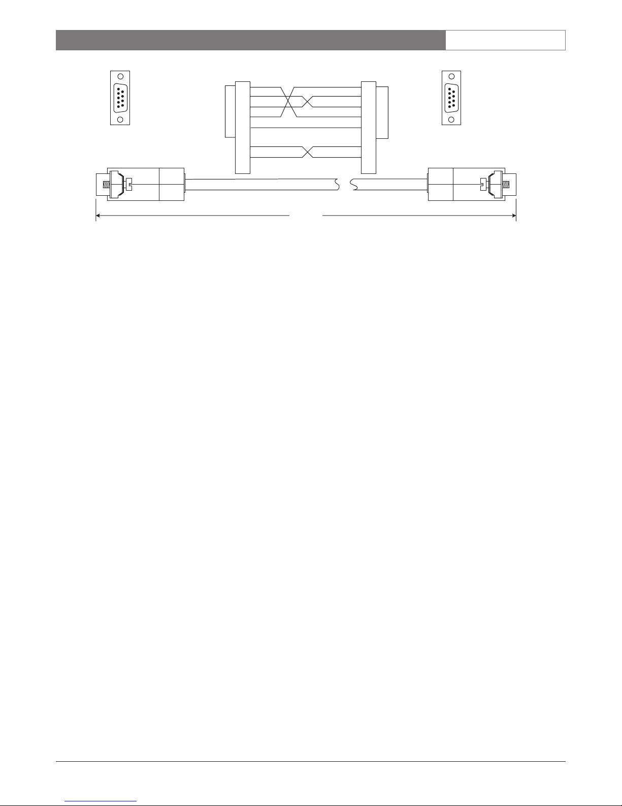
A CONSOLE port to standard 9-pin PC serial port cable
is available by ordering Bosch Part Number S1385.
LTC 2600 Series | Instruction Manual | Introduction
Bosch Security Systems | July 12, 2004
EN
|
8
CONSOLE Cable Pinouts
Conditions for Proper Command Execution
The LTC 2600 multiplexer will accept and execute CCL
commands only when the multiplexer is not involved in a
system reset and the front panel keypad is not in use.
Commands sent under these conditions will be ignored
and will produce one of the following error messages:
ERROR: Console Command ignored; Multiplexer is
resetting.
ERROR: Console Command ignored; Multiplexer local
front panel keypad is in use, or timing out.
When the programming menu is being used by a system
operator, the multiplexer will remain under the operator's
control until the menu is exited.
CAUTION: There are two important exceptions to the
rules of protocol as stated in this section: the RESETSYSTEM and DEFAULT commands will be executed
whenever received. Using the DEFAULT command will
cause the loss of all previously entered user settings.
When a CCL command is received that contains an error
in its format or parameter values, a descriptive message
(as to the nature of the error) will be sent to the console.
The execution of the CCL command will be aborted at
the point of the error or illegal parameter value.
Following are some sample error messages:
Illegal Command Message: MS-ALARM-CAPTURE 1
(illegal capture time value)
Error Message: ERROR: CAPTURE TIME
(must be 0 (off), or 3 to 60 seconds.)
3.1 CCL Command Formats
The LTC 2600 Series Command Console Language
contains commands which control the operation of the
multiplexer specifically (e.g. starting and stopping
encoding, etc.), as well as commands that generally
apply to the whole system's operation (e.g. setting
system time and date information, etc.) Commands
that apply only to the multiplexer operation use an M
prefix, usually in combination with other prefixes
which further specify the command function (see the
following descriptions). Commands that are general in
nature do not use a prefix.
Prefix Description
M (Multiplexer) Indicates the command is a
multiplexer-specific command.
S (Select) Indicates the command selects or sets
a multiplexer system parameter.
R (Read) Indicates the command is requesting
that the multiplexer respond with the
value of its setting. Note that dashes
(-), if shown, must be used in the
command line.
Prefix combinations used in the LTC 2600 Series CCL
include MS and MR (examples provided here for
reference).
MS Command Examples
Multiplexer Set commands are used to set (or select) a
specific multiplexer operating function.
MS-ACTION-CAPTURE (time)
This command sets the action capture time by allowing
you to specify that parameter (from 3 to 60 seconds)
where (time) is shown in the command syntax.
72.0"
9 pin female
PC Serial Port
Connector
LTC 2600 Console Port
1
2
3
4
5
6
7
8
9
9 pin female
1
2
3
4
5
6
7
8
9
1
2
3
4
5
6
7
8
9
1
2
3
4
5
6
7
8
9

LTC 2600 Series | Instruction Manual | Introduction
Bosch Security Systems | July 12, 2004
EN
|
9
NOTE: Some MS commands require that a 16-position
(bit) table be entered as the value of the parameter that
is being set--e.g. MS-ALARM-ENABLE (Table 16). An
example of how to complete this syntax is provided
below.
MS-ALARM-ENABLE 65535 (If decimal entry mode
is being used)
OR
MS-ALARM-ENABLE FFFF (If hexadecimal entry
mode is being used)
Either of these commands enables Alarms 1 through
16 by specifying a value that represents a 16 position
(bit) table having all bits set to 1 (1 Enables an Alarm,
0 Disables an Alarm). An illustration of how the table
values are specified (binary equivalent), and additional
examples, are shown in Table 16.
Alarm No.: 16 15 14 13 12 11 10 987654321
Position (Bit) #:
15 14 13 12 11 10 9 876543210
All Alarms Enabled,
Table Value 65535:
(FFFF hex)
1111111111111111
All Alarms Disabled,
Table Value 0:
(0 hex) 0000000000000000
Alarms 1-4 Enabled,
Table Value 15:
(000F hex) 0000000000001111
Table 16
MR Command Examples
Multiplexer Read commands are used to acquire the
current settings of a multiplexer which has been set up
through its local front panel keypad or by CCL
commands. When an MR command is sent, the
multiplexer responds in the following format with the
requested data:
• The data is preceded by a space, colon, and a
space on the same line as the command.
•Multiple items of data are separated by spaces.
•Text data is surrounded by double quotes.
•Numeric data is always returned as a decimal
number, even if the HEX command has
selected hexadecimal entry of numeric values.
• An ENTER (return) ends the data.
NOTE: The responses are shown in the following
examples:
MR-ACTION-CAPTURE: 10
Returned time of 10 seconds.
MR-VCR-ENCODE-LIST: 1 2 10 11 12 16 5
Returned camera numbers in the VCR encode list.
MR-CAM-TITLE 1: LOBBY CAMERA
Returned text of the title for camera 1.
General Command Examples
General commands are used to set or read parameters
relating to general system functions. These commands
do not use any prefixes in their syntax.
SET-RS-232 (baud) (data bits) (parity) (stop bits)
(handshake) With specific numeric values assigned for
the parameters in parentheses, this command sets the
RS-232 communication protocol.
DATE
Displays system date information.
3.2 CCL Command Function
CCL commands correspond by function to the
multiplexer menu selections used during keypad entry
of the same settings. Some multiplexer menu selections
do not have a corresponding CCL command, since the
same capability is provided by another CCL command
(e.g. there are no Disable All Alarms or Enable All
Alarms CCL commands because the single MSALARM-ENABLE CCL command allows the
operator to enable none, all, or any specific alarms.)
Similarly, when a front panel keypad entry of Disable
All Alarms or Enable All Alarms is read back using an
MR command, it will be reflected in the value of the
returned Table 16 value (e.g. Disable All Alarms is read
back as a 0, Enable All Alarms is read back as 65535).
Alarm Enable, Action Enable, and Video Color Enable
all have front panel keypad entry Disable All/Enable All
options, and will function likewise.
Numeric values in the command descriptions in the
following sections in this manual assume the
DECIMAL entry mode has been selected. Where
hexadecimal values are also given, they are designated
(hex).
Camera numbers referenced in the commands always
refer to the numbers marked on the rear panel of the
multiplexer. Camera numbers displayed on the
monitor(s) can be offset from the rear panel numbers
by using the MS-CAM-NUMBER command.

LTC 2600 Series | Instruction Manual | Multiplexer Set (MS) Commands
Bosch Security Systems | July 12, 2004
EN
|
10
4MULTIPLEXER SET (MS)
COMMANDS
4.1 Summary of MS Commands
Command <parameters>
MS-ACTION-ALARM-RELAY <responds to> <polarity>
MS-ACTION-BEEPER <boolean>
MS-ACTION-CAPTURE <time>
MS-ACTION-CLEAR <camera map>
MS-ACTION-ENABLE <table 16>
MS-ACTION-HISTORY <camera map>
MS-ACTION-SENSITIVITY <camera#> <level>
MS-ACTION-SETUP <boolean> <boolean>
MS-ACTION-ZONEDRAW <zone draw setting>
MS-ACTION-ZONEGROUP <camera#> <table 8>
MS-ACTION-ZONES <camera#> <map row#> <zone map row>
MS-ACTIVE-CAMEO <monitor> <cameo#>
MS-ADDRESS <unit address>
MS-ALARM-BEEPER <boolean>
MS-ALARM-CAPTURE <time>
MS-ALARM-CLEAR <camera map>
MS-ALARM-ENABLE <table 16>
MS-ALARM-HISTORY <camera map>
MS-ALARM-POLARITY <table 16>
MS-ALARM-SETUP <boolean> <boolean>
MS-AUTOPRINT <boolean>
MS-AUTOSET <boolean> <boolean> <boolean> <boolean>
<boolean>
MS-CAM-AUTOCOLOR <auto-detect>
MS-CAM-COLOR <table 16>
MS-CAM-FULL <monitor> <camera#>
MS-CAM-NUMBER <starting-number>
MS-CAM-TITLE <camera#> <"text">
MS-CAM-VIDEOLOSS-MESS <table 16>
MS-DISPLAY-MODE <monitor> <display-mode>
MS-FREEZE <monitor> <cameo#> <boolean>
MS-HELP
MS-KEY-LOCKOUT <boolean>
MS-LANGUAGE <language>
MS-LOG-SETUP <boolean> <boolean> <boolean> <boolean>
<boolean>
MS-MON-A-DISPLAY <mode> <camera list>
MS-MON-BORDERS <brightness>
MS-MON-LARGE-TEXT <text-bright> <background-bright>
MS-MON-SMALL-TEXT <text-bright> <background-bright>
MS-MON-TEXT <brightness> <brightness>
MS-MON-TEXT- E NABLE <monitor> <boolean>
MS-MON-TIME-DATE-FORMAT <time-format> <date-format>
MS-MON-TIME-ENABLE <monitor> <boolean>
MS-MON-TIME-POSITION <location>
MS-OPERATION <operation>
MS-OPERATION-SIMPLEX <mode>
MS-OPERATION-DUPLEX <mode-D1> <mode-D2>
MS-PASSWORD <password> <password> <password>
MS-SEQ-DWELL <monitor> <mon-mode> <time>
MS-SEQ-DWELL-TIME <seq-device> <dwell-time>
MS-SEQ-ENABLE <monitor> <boolean>
MS-SEQ-LIST <monitor> <display-mode> <camera list>
MS-SEQ-MON-A <seq-mode> <camera list>
MS-SEQ-MON-B <camera list>
MS-SETUP-TITLE <setup#> <text>
MS-STATUS <camera map> <camera map> <camera map>
MS-SUMMER-TIME <date>
MS-SYSTEM-SETTINGS <action>
MS-TIME-EVENT <item> <begin-date> <begin-time> <end-date>
<end-time> <function> <log> <interval> <SMTWTFS> <status>
MS-TIME-EVENT-COMMAND <command#> <"CCL command">
MS-TIME-EVENT-CONTROL <action>
MS-TIME-EVENT-STATUS <start-item> <end-item> <status>

LTC 2600 Series | Instruction Manual | Multiplexer Set (MS) Commands
Bosch Security Systems | July 12, 2004
EN
|
11
4.2 Detailed Descriptions of MS
Commands
MS-ACTION-ALARM-RELAY <responds to>
<polarity>
NOTE: This command controls Relay 1 only.
This command allows you to set the action/alarm
contacts to close on any action or alarm and change
the multiplexer encoding speed to the action/alarm
recording speed set by the MS-VCR-TI ME -LAPSE
command.
Parameter values for <responds to> and <polarity> are
as follows:
<responds to> 0 Neither (never activates>
1 Relay activates on action
2 Relay activates on alarm
3 Relay activates on action or
alarm
<polarity> 0 Normally open (N/O)
1Normally closed (N/C)
CAUTION: Before making connections to the
action/alarm relay contacts, refer to the LTC 2600
Series Video Multiplexer Instruction Manual for relay
contact ratings.
MS-ACTION-BEEPER <boolean>
This command enables or disables the beeper when an
action condition is present.
Parameter values are: 0 Disabled
1 Enabled
MS-ACTION-CAPTURE <time>
This command allows you to set a specified duration
(from 3 to 60 seconds) for system indications of an
action condition.
Parameter values for <time> are any value from <3>
to <60> seconds.
NOTE: If a value less than <3> is entered (i.e. <0>…<2>),
the value will automatically be set to 3 seconds.
MS-ACTION-CLEAR <camera map>
This command clears the action status of the
multiplexer. For each bit which is 1 <camera map>,
the action status will be cleared.
NOTE: The <camera map> consists of a 16-bit map
with a bit for each camera in the multiplexer. The least
significant bit corresponds to camera 1; the most
significant bit corresponds to camera 16. A set bit
corresponds to an enabled or active camera, depending
on the contact.
MS-ACTION-ENABLE <table 16>
This command enables multiplexer action detectors
corresponding to the values specified in a 16-position
(bit) table. The value in each position of the table
corresponds to the state of a specific action detector (a
value of 1 enables the action detector; a value of 0
disables the action detector).
Parameter values for <table 16> range from <0> to
<65535> (decimal) OR <0> to <FFFF> hex.
EXAMPLE: To enable ONLY Action Detectors 1-4, a
value of 15 decimal (000F hex) is used for <table 16>.
Action Detect. No.:
16 15 14 13 12 11 10 987654321
Position (Bit) #:
15 14 13 12 11 10 9 876543210
1-4 Enabled,
Table Value 15:
(000F hex) 0000000000001111
MS-ACTION-H ISTORY <camera map>
This command clears the action status history for
cameras in the camera map.
NOTE: The <camera map> consists of a 16-bit map
with a bit for each camera in the multiplexer. The least
significant bit corresponds to camera 1; the most
significant bit corresponds to camera 16. A set bit
corresponds to an enabled or active camera, depending
on the contact.

LTC 2600 Series | Instruction Manual | Multiplexer Set (MS) Commands
Bosch Security Systems | July 12, 2004
EN
|
12
MS-ACTION-SENSITIVITY <camera#> <level>
This command sets the action detector sensitivity for
each specified camera to a certain level.
Parameter values for <camera# > and <level > are as
follows:
<camera# > 1 to 16
<level> 1 to 4 (with 4 being the highest
sensitivity)
MS-ACTION-SETUP <boolean> <boolean>
This command sets the action manual reset and
camera history settings, respectively.
Parameter values are: 0 Disabled
1 Enabled
MS-ACTION-ZONEDRAW <zone draw setting>
NOTE: This command is only supported for binary
protocol.
This command enables or disables real-time zone
drawing on monitor A.
Parameter values for <zone draw setting> are:
0 Disabled
camera# Enabled; the specified camera is
selected for monitor A in full-screen
mode, and real-time drawing is
enabled for that camera-overriding
any other use of monitor A.
MS-ACTION-ZONEGROUP <camera#> <table 8>
This command enables more detailed, specialized
setup of groups of action detector zones. (Individual
action zone selection is normally accomplished using
monitor A and the front panel keypad.)
Parameter values for <camera# > range from <1> to
<16>. Parameter values for <table 8> range from <0>
to <255> (decimal) OR <0> to <FF> (hex). Table 8 is
an 8-position (bit) table where the value in each
position corresponds to the state of a specific action
detection zone group (i.e. <1> enables the zone group;
<0> disables the zone group.)
EXAMPLE: To enable camera number 1, action
detection zone groups 4, 7, and 8; a value of <1> is
used for <camera#>, and a value of <200> decimal
(C8 hex) is used for <table 8>.
Monitor Zone Groups
Zone Group No.: 87654321
Position (Bit) # 76543210
Zones 4, 7, and 8 Enabled, Table Value 200:
(C8 hex) 11001000
Table 8
MS-ACTION-ZONES <camera#> <map row#>
<zone map row>
This command sets the specified map row in the action
zone map for the specified camera.
Parameter values for <camera#>, <map row#>, and
<zone map row> are defined as follows:
<camera# > 1 to 16
<map row#> 1 to 16
<zone map row> A 16-bit word, corresponding
to the map row points where
the zone map bit 0 is the
most right point, and the
zone map bit 15 is the most
left point.
MS-ACTIVE-CAMEO <monitor> <cameo#>
This command sets the specified cameo as the active
cameo for the specified monitor. Any non-valid
<cameo#> will be ignored.
Parameter values for <monitor> and <cameo#> are as
follows:
<monitor> 1 Monitor A
2Monitor B
<cameo#> 1 to 16
MS-ADDRESS <unit address>
This command sets the unit address for the
multiplexer. The unit address is used by the external
keyboard to select a particular multiplexer. Each
multiplexer in the system must have a unique address,
although this cannot be verified automatically by the
multiplexer.
Parameter values for <unit address> range from
<1> to <30>.
1 2 3 4
5 6 7 8

LTC 2600 Series | Instruction Manual | Multiplexer Set (MS) Commands
Bosch Security Systems | July 12, 2004
EN
|
13
MS-ALARM-BEEPER <boolean>
This command enables or disables the beeper when an
alarm condition is present.
Parameter values are: 0 Disabled
1 Enabled
MS-ALARM-CAPTURE <time>
This command allows you to set a specified duration
(from 3 to 60 seconds) for system indications of an
alarm condition.
Parameter values for <time> are any value from
<3> to <60> seconds.
NOTE: A value of <0> for <time> sets latch mode. If
a value of <1> or <2> is entered, the value will
automatically be set to 3 seconds.
MS-ALARM-CLEAR <camera map>
This command clears the alarm status of the
multiplexer. For each bit which is 1 <camera map>,
the alarm status will be cleared.
NOTE: The <camera map> consists of a 16-bit map
with a bit for each camera in the multiplexer. The least
significant bit corresponds to camera 1; the most
significant bit corresponds to camera 16. A set bit
corresponds to an enabled or active camera, depending
on the contact.
MS-ALARM-ENABLE <table 16>
This command enables multiplexer alarms
corresponding to the values specified in a 16-position
(bit) table. The value in each position of the table
corresponds to the state of a specific alarm (a value of
1 enables the alarm; a value of 0 disables the alarm).
Parameter values for <table 16> range from <0> to
<65535> (decimal) OR <0> to <FFFF> hex.
EXAMPLE: To enable ONLY alarms 1-4, a value of
<15> decimal (000F hex) is used for <table 16>.
Alarm No: 16 15 14 13 12 11 10 987654321
Position (Bit) #:
15 14 13 12 11 10 9 876543210
1-4 Enabled, Table Value 15:
(000F hex) 0000000000001111
MS-ALARM-HISTORY <camera map>
This command clears the alarm status history for
cameras in the camera map.
NOTE: The <camera map> consists of a 16-bit map
with a bit for each camera in the multiplexer. The least
significant bit corresponds to camera 1; the most
significant bit corresponds to camera 16. A set bit
corresponds to an enabled or active camera, depending
on the contact.
MS-ALARM-POLARITY <table 16>
This command allows you to select normally open and
normally closed switches for alarms.
The <table 16> parameter ranges in value from <0> to
<65535> (decimal) OR <0> to <FFFF> (hex). Table
16 is a 16-position (bit) table where the value in each
position corresponds to the type of a specific alarm
switch (0 selects normally open alarm switches; 1
selects normally closed alarm switches.
EXAMPLE: To select Normally Open (N/O) alarm
switches for alarms 1-8 and Normally Closed (N/C)
alarm switches for alarms 9-16, a value of <65280>
decimal (FF00 hex) is used for <table 16>.
Alarm No: 16 15 14 13 12 11 10 987654321
Position (Bit) #:
15 14 13 12 11 10 9 876543210
1-8 N/0, 9-16 N/C, Table Value 65280:
(FF00 hex) 1111111100000000
MS-ALARM-SETUP <boolean> <boolean>
This command sets the alarm manual reset and camera
history settings, respectively.
Parameter values are: 0 Disabled
1Enabled
MS-AUTOPRINT <boolean>
This command enables or disables automatic printing
of the log. If enabled, the command will take effect
when the serial port function is set to PRINT.
Parameter values are: 0 Disabled
1Enabled

LTC 2600 Series | Instruction Manual | Multiplexer Set (MS) Commands
Bosch Security Systems | July 12, 2004
EN
|
14
MS-AUTOSET <boolean> <boolean> <boolean>
<boolean> <boolean
This command carries out the autoset function for the
current setup for each of the following: record, video
loss, sequence, alarm, and action list respectively.
Parameter values are: 0 Disabled
1 Enabled
MS-CAM-AUTOCOLOR <auto-detect>
This command enables or disables the multiplexer
autocolor operation. When autocolor is enabled, the
system automatically enables color operation for any
color camera connected to the system (or added later).
When autocolor is disabled, the multiplexer will use
the results of the last autocolor detection to enable the
color operation of the cameras (unless an MS-CAM-
COLOR command is sent).
Parameter values for <auto-detect> are:
0 Disables Autocolor
1 Enables Autocolor
MS-CAM-COLOR <table 16>
This command allows the color operation of the
cameras connected to the system to be manually
selected.
NOTE: AUTOCOLOR is automatically disabled
whenever and MS-CAM-COLOR command is sent.
The <table 16> parameter ranges in value from <0> to
<65535> (decimal) OR <0> to <FFFF> (hex). Table
16 is a 16-position (bit) table where the value in each
position corresponds to the color operation of a
specific camera (i.e. a value of 1 enables color; a value
of 0 disables color).
EXAMPLE: To enable color on only cameras 1-4, a
value of <15> decimal (000F hex) is used in <table
16>.
Camera No.: 16 15 14 13 12 11 10 987654321
Position (Bit) #:
15 14 13 12 11 10 9 876543210
1-4 Enabled, Table Value 15: (000F hex)
0000000000001111
MS-CAM-FULL <monitor> <camera#>
This command assigns the specified camera to the
specified monitor if the monitor is in full screen mode.
NOTE: If the monitor is not is full screen mode, the
command has no effect.
Parameter values for <monitor> and <camera#> are:
<monitor> 1 Monitor A
2Monitor B
<camera#> 1 to 16
MS-CAM-NUMBER <starting-number>
This command sets the starting camera number to be
displayed on the monitor when the camera connected
to rear panel camera input #1 is selected.
Parameter values for <starting-number> range from
<1> to <983>.
EXAMPLE: If you wanted to set 101 as the number to
be displayed on the monitor(s) when the camera
connected to rear panel camera input #1 is selected,
you would enter <101> as the value for <startingnumber>. The camera connected to rear panel camera
input #2 would then automatically be displayed as
camera 102, and so on.
MS-CAM-TITLE <camera#> <"text">
This command specifies a camera title to be displayed
on the monitor screen.
Parameter values for <camera#> and <"text"> are as
follows:
<camera#> 1 to 16
<"text"> Valid characters are: A to Z
(uppercase only), 0 to 9, space, * + , . / : [ ], 16 characters maximum (not
including double quotes which must
be used on either side of the text)
NOTE: Each camera's title is set individually. The
camera title entered must begin and end with double
quotation marks, as shown in the command syntax
(these marks will not be shown on the screen). If
lowercase characters are used, they will automatically
be converted to uppercase. Any illegal characters will
be replaced with a ":?".

LTC 2600 Series | Instruction Manual | Multiplexer Set (MS) Commands
Bosch Security Systems | July 12, 2004
EN
|
15
MS-CAM-VIDEOLOSS-MESS <table 16>
This command enables or disables video loss messages.
The <table 16> parameter ranges in value from <0> to
<65535> (decimal) OR <0> to <FFFF> (hex). Table
16 is a 16-position (bit) table where the value in each
position corresponds to the video loss messages status
of a specific camera (i.e. a value of 1 enables video loss
messages; a value of 0 disables the video loss
messages).
NOTE: Video loss messages can be disabled for
connected or disconnected cameras. When a camera
with videoloss message disabled is connected to the
system, the videoloss message is not automatically
enabled (i.e. the command must be given to enact a
change in this function).
EXAMPLE: To disable video loss messages related to
camera 1, a value of <65534> decimal (FFFE hex) is
used for <table 16>.
Camera No: 16 15 14 13 12 11 10 987654321
Position (Bit) #:
15 14 13 12 11 10 9 876543210
1-4 Enabled, Table Value 15:
(000F hex) 0000000000001111
MS-DISPLAY-MODE <monitor> <display-mode>
This command sets the display mode for the specified
monitor.
Parameter values for <monitor> and <display-mode>
are:
<monitor> 1 Monitor A
2Monitor B
<display-mode> 0 Full Screen
1Single Quad
23 x 3 Multi
34 + 3 Multi
412 + 1 Multi
54 x 4 Multi
68 + 2 Multi
NOTE: Selecting Quad mode will loop between
available quad modes. For non-duplex, System4 units,
only Full Screen mode will be accepted for monitor B.
MS-FREEZE <monitor> <cameo#> <boolean>
This command enables or disables the freeze function
for the specified cameo on the specified monitor.
NOTE: If the specified monitor is in full screen mode,
the cameo specification is redundant (i.e. unnecessary).
Parameter values for <monitor>, <cameo#> and
<boolean> are:
<monitor> 1 Monitor A
2Monitor B
<cameo#> 1 to 16
<boolean> 0 Disable
1 Enable
MS-HELP
This command displays a screen of help instructions
regarding MS command entry.
MS-KEY-LOCKOUT <boolean>
This command sets or clears the lockout flag for the
front panel and external keypad. When set, all front
panel and external keystrokes are ignored. PTZ
commands continue to be accepted from the external
keypad.
Parameter values are: 0 Disabled
1Enabled
MS-LANGUAGE <language>
This command specifies the language for the
multiplexer.
Parameter values for <language> are:
1 English
2German
3French
4 Spanish
5 Italian
6 Dutch
 Loading...