

Page 1
DCN Next Generation
Automatic Camera Control
en Software User Manual
LBB 4162/00
LBB 4188/00
Page 2
About this manual
This user manual is divided into three chapters.
Chapters 1 and 2 provide background information
and chapter 3 provides detailed user information as
follows:
• Chapter 1 - Automatic Camera Control -
containing general information about the
Automatic Camera Control software, and the two
different versions available.
• Chapter 2 - Getting Started - containing details
about installing the stand-alone version of the
software, and information about starting the
application from the Startup screen and from a
shortcut icon. There is also a description of the
Help facility.
• Chapter 3 - Using Automatic Camera Control -
containing details about configuring the software,
assigning cameras to seat/unit numbers,
specifying camera type, editing camera IDs,
importing and exporting camera settings and
printing Camera Installation files.
Manual conventions
For clarity this user manual uses consistent styles,
symbols and typographical conventions. They are:
i Note
General notes are contained within rules and
indicated with this symbol at the left margin.
Notes are used to draw attention to special
actions or information.
i Caution
A caution is contained within rules and
indicated with this symbol at the left margin.
Cautions are used to draw attention to actions
or commands that could lead to a loss of
information or damage to equipment
i Tip
A tip is contained within a box and indicated
with this symbol at the left margin. Tips are
used to provide supplementary information that
may make an action quicker or easier to carry
out.
• An action (to be carried out by the user) is shown
with a larger round bullet mark.
Typographical conventions
The following typographical conventions (text styles)
are used in this manual:
• Typed input - information to be typed in using
the keyboard is shown as:
Filename
• Single key - input via a single key (or keys) on
the keyboard is shown as:
<enter>, <shift>, etc.
• Multiple keys - input via a combination of keys
pressed together is shown as:
<ctrl>+<p>, <alt>+<f4>
• Screen text - information that appears on screen
is shown as:
‘Choose Startup Modules:’
Hyperlinks
This manual is also available as a digital document in
the Adobe Portable Document Format (PDF). All
references to pages, figures, tables, etc. in this digital
document contain hyperlinks to the referenced location.
Page 3

DCN Next Generation Automatic Camera Control en | 3
Table of contents
1 Automatic camera control ....................................4
1.1 About Automatic Camera Control...................... 4
1.1.1 What is Automatic Camera Control? ................ 4
1.1.2 Camera Control in congress applications ........ 4
1.2 Stand-alone and PC controlled system
versions
1.2.1 Differences between stand-alone and PC
controlled systems
1.3 Overview of Automatic Camera Control........... 4
1.3.1 Systems using Control PC................................... 4
1.3.2 Stand-alone systems ............................................. 4
2 Getting started............................................................5
2.1 Starting the Automatic Camera Control
software
2.1.1 The Startup screen ................................................ 5
Selecting an installation (and a names) file...... 5
The Automatic Camera Control icon................. 5
2.2 Installing the stand-alone version........................ 5
2.2.1 PC requirements and settings............................. 5
2.2.2 Installing the stand-alone software..................... 5
2.3 Using Help ...............................................................6
2.3.1 The Help menu........................................................ 6
2.3.2 Index .......................................................................... 6
2.3.3 Keyboard .................................................................. 6
2.3.4 Commands............................................................... 6
2.3.5 Procedures............................................................... 6
2.3.6 Glossary.................................................................... 6
2.3.7 Using Help ............................................................... 7
2.3.8 About ......................................................................... 7
3 Using Automatic Camera Control..................... 8
3.1 The camera installation main window................ 8
3.1.1 The menu bar........................................................... 9
3.2 Assigning cameras to seat/unit numbers ......... 9
3.2.1 Specifying the overview camera .......................10
3.2.2 Selecting a seat (or unit) number .....................10
3.2.3 Selecting camera number ..................................10
3.2.4 Editing camera ID .................................................10
3.2.5 Specifying camera type.......................................11
3.2.6 Entering seat (or unit) text ..................................11
3.2.7 Inserting seat (or unit) numbers and camera
settings
3.2.8 Editing entries in the ‘Assignments:’ list .........13
3.2.9 Deleting a camera assignment from the
‘Assignments:’ list
3.3 System setting.......................................................13
3.3.1 Screenline usage ..................................................14
3.3.2 Double seat (or unit) text ....................................14
3.3.3 Camera override ...................................................14
3.3.4 Camera movement time ......................................14
3.3.5 Number of audience monitors ...........................14
3.4 The file menu .........................................................15
3.4.1 Camera activity......................................................15
3.4.2 Clear all ...................................................................15
..................................................................... 4
................................................. 4
.................................................................... 5
....................................................................12
.................................................13
3.4.3 Printing.................................................................... 15
3.4.4 Importing and exporting Camera Installation
files
.......................................................................... 15
3.4.5 Importing Camera Installation files ................... 16
3.4.6 Exporting Camera Installation files ................... 16
3.5 Exiting Automatic Camera Control................... 16
3.5.1 Temporarily exiting Automatic Camera Control16
3.5.2 Permanently exiting Automatic Camera
Control
.................................................................... 17
Bosch Security Systems B.V. | 2005 January | 9922 141 70491
Page 4

DCN Next Generation Automatic Camera Control en | 4
1 Automatic camera control
1.1 About Automatic Camera Control
1.1.1 What is Automatic Camera Control?
The Automatic Camera Control software is designed
to interface DCN Next Generation congress systems
with Bosch Allegiant switchers or a single Bosch
AutoDome camera. It selects fixed or pre-positioned
cameras to be activated to display the current active
speaker at a conference.
1.1.2 Camera Control in congress applications
When a chairman’s or delegate’s microphone is
activated on the equipment, the camera assigned to
that position is activated. When no microphones are
active, an overview camera is automatically selected.
The image can be displayed on hall displays or other
monitors together with information about the current
speaker if required (such as delegate identification).
The system operator has a monitor, which also
displays information about which camera is active.
This system provides an extra dimension to congress
and conference proceedings.
i Note
The Allegiant video control switcher cannot
display graphic characters that are used in
certain non-European and non-US languages
such as Chinese.
1.2 Stand-alone and PC controlled
system versions
There are two versions of DCN Automatic Camera
Control software:
• PC controlled version is for systems with a CCU
and a control PC. The activation and installation
of the cameras is integrated into the PC control
software.
• Standalone version is for stand-alone systems
without PC control.
There are also minor differences in functionality
between the two software versions. These are
described elsewhere in this manual.
1.3 Overview of Automatic Camera
Control
An overview of the procedure for using the
Automatic Camera Control software is given below.
1.3.1 Systems using Control PC
The Automatic Camera Control software is installed
on the control PC. The control PC is connected to
the CCU, which in turn is connected to delegates’
contribution units. The CCU is also connected to a
single AutoDome camera or an Allegiant video
switcher, which in turn is connected to the cameras
and monitors in the system. After connecting the
system, the Automatic Camera Control software is
used to configure the cameras. The control PC
remains connected to the CCU while the system is
being used.
1.3.2 Stand-alone systems
In stand-alone systems, a temporary PC connection
to the CCU and AutoDome camera or Allegiant
video switcher is needed during camera installation.
The numbers assigned to the contribution units
during system initialisation are coupled to camera
positions. After configuration is complete, the PC is
disconnected from the system, and a direct
connection from the CCU to the AutoDome camera
or the Allegiant video switcher is made. Operational
camera control by the CCU is enabled during
installation. To disable operational camera control, it
is necessary to re-connect the installation PC and
open the Camera Installation file.
i Note
For details on connections refer to the DCN
Next Generation Installation and User
Instructions.
1.2.1 Differences between stand-alone and PC
controlled systems
The main difference is that the stand-alone version
operates without a control PC. A PC needs only be
connected for programming the CCU. The PC
running the stand-alone software is disconnected
from the CCU after the software has been used, but
in a DCN Next Generation system with control PC,
the PC remains connected to the CCU.
Bosch Security Systems B.V. | 2005 January | 9922 141 70491
Page 5
DCN Next Generation Automatic Camera Control en | 5
2 Getting started
2.1 Starting the Automatic Camera
Control software
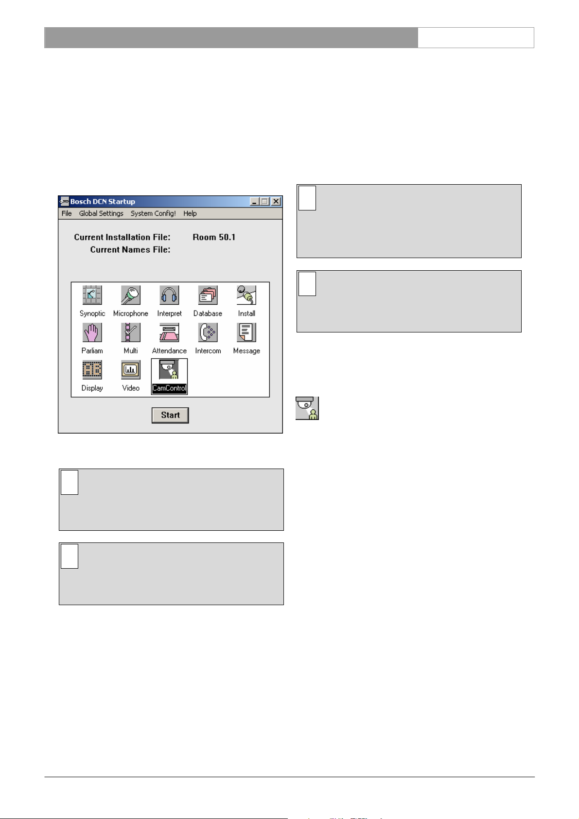
2.1.1 The Startup screen
The Automatic Camera Control program is started
from the Startup screen (shown below).
• Names file - containing information about the
name, seat number and other conference and
personal details of participating delegates. Names
files are created using Delegate Database.
The seat numbers defined in System Installation are
used to assign cameras connected to the system. The
seat numbers are assigned using the System
Installation software (LBB4185).
i Note
An installation file must be open before camera
installation is possible. However, the Automatic
Camera Control software can be started
without an installation file being open.
i Note
The stand-alone version of the Automatic
Camera Control software does not use other
software modules.
Selecting an installation (and a names) file
For details on selecting an installation (and a names)
file, please refer to the Startup user manual (LBB
4190).
Figure 1 The Startup screen.
i Note
For starting the Startup program from an icon
in the desktop, refer to the Startup user
manual.
i Note
The standalone version of the Automatic
Camera Control software is started from the
windows ‘Start Programs’ menu.
The Automatic Camera Control PC controlled
version uses two user-created files that contain
important information about the installed hardware
configuration and about delegates’ names. These files
are:
• Installation file - containing information about
channel assignment and the numbers that have
been assigned to all microphones connected to
the system. These seat numbers are assigned
using the System Installation software module
LBB 4185/00.
The Automatic Camera Control icon
For details on the Automatic Camera Control icon
and how to start Automatic Camera Control from
Startup, please refer to the Startup user manual (LBB
4190).
2.2 Installing the stand-alone version
2.2.1 PC requirements and settings
For information about PC requirements and settings,
please refer to the DCN Next Generation Installation
and User Instruction.
2.2.2 Installing the stand-alone software
To install the stand-alone version of the Automatic
Camera Control software:
• Insert the CDROM with type number LBB
4162/00.
• Select ‘Run...’ from the ‘Start’ menu on the
Windows desktop.
• Type d:\setup (where d is the CDROM) on the
command line which appears.
• Follow the on-screen instructions.
When installation has been successfully completed, a
new program group called Standalone Camera
Bosch Security Systems B.V. | 2005 January | 9922 141 70491
Page 6

DCN Next Generation Automatic Camera Control en | 6
Control Installation is created. Please refer to
paragraph 2.1, for information about starting the
module.
i Note
Before beginning camera installation, it is
important to make sure that the Allegiant video
switcher, system cameras and monitors are
properly connected and installed. For more
information, refer to the DCN Next Generation
Installation and User Instructions.
2.3 Using Help
2.3.1 The Help menu
The ‘Help’ menu in the title bar contains commands
for an on-screen help facility. This help facility
contains information on all commands in the ‘File’
menu, on which keyboard keys are functional, a
description of how to use the software, information
on how to use the help facility itself, plus an index
and a glossary of terms. All information contained in
this user manual is also found in the ‘Help’ facility.
The ‘Help’ facility contains the following options:
• Index
• Keyboard
• Commands
• Procedures
• Glossary
• Using Help
• About…
A list of different key types is given. For more
information on any key type contained in the list:
• Click on the required key type in the list.
An on-screen page with the requested information
will appear.
2.3.4 Commands
This gives information on all menu options, covering
the ‘File’, ‘Edit’, ‘View’, ‘Settings’ and ‘Help’ menus.
To access the ‘Commands’ help facility:
• Select the ‘Help’ menu and click on
‘Commands’.
A list of menu groups is given. For more information
on any menu group contained in the list:
• Click on the required menu group in the list.
A list of options in the selected menu group is given.
For more information on any option contained in the
list:
• Click on the required option in the list.
An on-screen page with the requested information
will appear.
2.3.5 Procedures
This gives information on how to use the software.
To access the ‘Procedures’ help facility:
• Select the ‘Help’ menu and click on
‘Procedures’.
A list of topics is given. For more information on any
topic contained in the list:
2.3.2 Index
To access the index:
• Select the ‘Help’ menu and click on ‘Index’.
A full list of subjects covered by the help facility is
given in alphabetical order. For more information on
any subject contained in the index:
• Click on the required subject in the index.
An on-screen page with the requested information
will appear.
2.3.3 Keyboard
This gives information on which keys on your
keyboard can be used with the software. This
includes using keys to activate menu items, to move
around in dialogue boxes, for short cuts, and to select
options from the main window. To access the
‘Keyboard’ help facility:
• Select the ‘Help’ menu and click on
‘Keyboard’.
• Click on the required topic in the list.
A list of options for the selected topic is given. For
more information on any option contained in the list:
• Click on the required option in the list.
An on-screen page with the requested information
will appear.
2.3.6 Glossary
To access the glossary:
• Select the ‘Help’ menu and click on
‘Glossary’.
A list of terms used in the help facility is given in
alphabetical order. For more information on any
term contained in the glossary:
• Click on the required subject in the index.
A window with the requested information will appear.
Bosch Security Systems B.V. | 2005 January | 9922 141 70491
Page 7

DCN Next Generation Automatic Camera Control en | 7
2.3.7 Using Help
This gives information on how to use the help facility.
To access the ‘Using Help’ facility:
• Select the ‘Help’ menu and click on ‘Using
Help’.
A list of topics is given. For more information on any
topic contained in the list:
• Click on the required topic in the list.
A list of options for the selected topic is given. For
more information on any option contained in the list:
• Click on the required option in the list.
An on-screen page with the requested information
will appear.
2.3.8 About
This provides software release information. To
display the ‘About...’ window:
• Select the ‘Help’ menu and click on
‘About ...’.
The following window appears:
Figure 2 The ‘About’ window
To remove this window:
• Click on the ‘OK’ push button.
Bosch Security Systems B.V. | 2005 January | 9922 141 70491
Page 8

DCN Next Generation Automatic Camera Control en | 8
3 Using Automatic Camera
Control
3.1 The camera installation main window
The Camera Installation main window is used to
assign fixed cameras and camera positions (on
preposition cameras) to DCN Next Generation units.
There are two main types of camera recognized by
the Automatic Camera Control software. Fixed
cameras are positioned before the conference begins,
and they remain in the same position during the
conference. Dome cameras can adjust their position
automatically in response to conference activity. For
example, a dome camera normally has several
prepositions, determined during configuration, each
covering a different delegate or group of delegates.
The camera will automatically change position to
cover the delegate who is speaking. The Camera
Installation window at startup is shown below.
• Camera specification edit fields for entering
camera number, camera ID, and the type of
camera (fixed or preposition)
When installation mode is entered (by pressing the
Start push button) for the first time i.e. when no
cameras have yet been assigned to seat numbers, or
when camera 1 is selected from the ‘Assignments’ list
the installation window appears as follows:
Figure 4 The Camera Installation window
Figure 3 The Camera Installation window (at startup)
i Note
The System Installation file is required for using
Automatic Camera Control with a softwarecontrolled DCN Next Generation system. This
file is loaded from the Startup screen. In the
example used in this manual, 10 seats have
been assigned in the System Installation file.
i Note
In the stand-alone version of the software,
‘seats’ are referred to as ‘units’.
The Camera Installation window contains the
following elements:
• Start/Stop push button. This is used to enter and
exit Installation mode.
i Note
If a camera with prepositions (such as a dome
camera) is selected, the number of
prepositions available, and the selected
preposition is also entered in this area.
• ‘Selected preposition:’ edit field (only displayed if
the camera is a preposition type)
• Seat (or unit) edit fields for selecting a seat (or
unit) number and entering one or two lines of
seat/unit text
• ‘Insert’ button for entering the camera and unit
assignments specified (it then appears in the
‘Assignments’ list on the right side of the main
window)
• ‘Delete’ button for removing camera and unit
assignments from the ‘Assignments’ list.
• ‘Assignments’ list for displaying assigned camera
data.
Bosch Security Systems B.V. | 2005 January | 9922 141 70491
Page 9

DCN Next Generation Automatic Camera Control en | 9
3.1.1 The menu bar
All menu options referred to in this user manual are
contained within the menu bar located under the title
bar at the top of the Camera Installation window.
The full list of menu options is as follows:
File Settings!... Configuration!
Camera
Clear all
Print…
Import…
Export…
E
xit
Activity
...
Camera List!... Help
Index…
Keyboard
Commands
Procedures
Glossary
Using Help
About…
3.2 Assigning cameras to seat/unit
numbers
i Note
Before you start the installation process make
sure that the configuration is correctly set.
To start the camera installation process:
• Click on the ‘Start’ button.
In this window must be select if an Allegiant video
switcher is used or not.
If ‘Yes’ is chosen the Allegiant Video Switcher (AVS)
mode is selected. If ‘No’ is chosen the Direct Camera
Control (DCC) mode is selected.
In case of AVS several cameras are connected via a
Allegiant video switcher to the system and
screenlines can be added to the camera images.
In case of DCC the camera is directly connected to
the system and only images with the addition of
screen lines can be used.
i Note
If you want to change the control mode at any
other time go to Configuration!... in the menu.
If there is no communication between the CCU and
the Allegiant video switcher, the following error
message appears:
Figure 7 No connection to video switcher error
message
i Note
The ‘Start’ button toggles to a ‘Stop’ button
when activated. During camera installation, all
conference activities will be stopped.
The following warning appears:
Figure 5 Camera installation warning
• Click on ‘OK’ to continue with camera
installation.
The following window appears:
• Click on ‘OK’ and ensure that the connection,
cable and communication settings between the
Allegiant video switcher and the CCU are
correctly made.
i Note
In case of Direct Camera Control there is no
warning when there is no connection between
the AutoDome and the CCU.
The following window appears:
Figure 8 The Camera Installation window
Figure 6 Configuration window
Bosch Security Systems B.V. | 2005 January | 9922 141 70491
Page 10

DCN Next Generation Automatic Camera Control en | 10
3.2.1 Specifying the overview camera
For Allegiant Video Switchers (AVS) Camera 1 is
always reserved for the overview. For Direct Camera
Control (DCC) the highest pre-position is reserved
for the overview. The overview gives a general
overview of the conference venue when all the
microphones are off (and therefore no conference
participant is on camera). In case of AVS the
overview camera can also be used when a dome
camera is moving from one preposition to another. It
acts as the default camera, and is activated when no
other camera is selected by the Allegiant video
switcher in response to conference activity.
The overview camera can be either a fixed or dome
camera. However, in single-camera configurations,
the overview camera is always a dome camera with
its last preposition showing the overview.
i Note
When a dome camera is used as the overview
camera, the ‘Camera movement time’ option
is disabled.
If a fixed camera is used, the edit fields for seat (or
unit) number and text are not displayed. It is not
possible to assign this camera to a seat or unit. The
following screen text is displayed:
‘This camera is reserved for the overview’
i Note
The camera ID for camera 1 is ‘greyed’ and
cannot be edited.
More detailed information about defining cameras is
given later in this section. After defining the overview
camera, it is necessary to save the setting. To do so:
• Click on the ‘Insert’ button.
The overview camera information will appear in the
‘Assignments’ list of the Camera Installation window.
The next seat or unit number which has not yet been
assigned to a camera will appear in the edit fields of
the Camera Installation window.
The Automatic Camera Control software will
automatically propose a seat or unit number in the
‘Seat nr:’ edit field of the Camera Installation
window. It is possible to accept this number, or to
change it using the up and down arrow keys of the
edit field. Alternatively, it is possible to press the
microphone button or any of the soft keys on a
contribution unit. This will automatically result in the
seat or unit number and any other entered
parameters appearing in the Camera Installation
window.
i Note
Selecting a seat or unit number causes the
LEDs of the soft keys, and the microphone LED
on the corresponding contribution unit to flash.
i Note
After pressing the ‘Insert’ push button, the
software automatically loads the next seat or
unit number which has not been assigned to a
camera.
The total number of seats (or units) which have not
yet been assigned to a camera is displayed in the
Camera Installation main window in the lower righthand corner:
‘n seats without camera assignment’
Where ‘n’ is the number of seats (or units).
Only seat (or unit numbers) without camera
assignment can be selected.
i Note
During installation, the audience monitor
continues to show the image from the overview
camera, except in one-camera configurations
where it will show the same view as the
operator monitor. The operator monitor shows
the selected camera picture.
3.2.2 Selecting a seat (or unit) number
In systems with PC control, the Automatic Camera
Control software takes the seat numbers from the
current installation file. In systems with a stand-alone
CCU, the Automatic Camera Control software uses
‘unit’ numbers instead of ‘seat’ numbers.
To enter or change the camera control settings for a
delegate’s contribution unit, it is first necessary to
select that unit’s seat or unit number. There are two
ways of selecting a seat or unit number.
Bosch Security Systems B.V. | 2005 January | 9922 141 70491
3.2.3 Selecting camera number
To continue with the camera installation, a camera
number should be assigned to each seat or unit
number. To do so:
• Select the number of the camera you want to
3.2.4 Editing camera ID
Each camera can have a descriptive ID (maximum
assign.
Page 11

DCN Next Generation Automatic Camera Control en | 11
16 characters) entered in the ‘Camera ID:’ edit field.
This, for example, could be used to give each camera
a descriptive ID relating to the position of the camera
in the conference venue. This text appears on the
operator monitor but not on audience monitors.
Figure 11 Camera edit fields for preposition cameras
The ‘Number of Prepositions’ edit field (default 99)
and the ‘Selected preposition’ edit field appear. To
Figure 9 Camera ID editing
To enter or edit the camera ID:
• Select the ‘Camera ID’ edit field.
assign a preposition to a seat (or unit):
• Click on the scroll-up or scroll-down button on
the ‘Selected preposition’ edit field.
• Enter the required text.
3.2.5 Specifying camera type
For AVS the type of camera (fixed or preposition)
must be specified. To specify a fixed camera:
• Click on the ‘Fixed:’ check box.
Figure 10 Camera edit fields for fixed cameras
A tick mark (√) appears to indicate that a fixed
camera type has been selected been selected. (This
option is not available for DCC).
• Click on the ‘Fixed:’ check box again to deselect
it.
i Note
When a preposition is changed, the operator
monitor displays the image assigned to that
preposition number using the Allegiant video
switcher.
Once the preposition is selected it must be defined
using the joystick on the Allegiant or virtual
keyboard. For more information, refer to the user
documentation for the Allegiant or virtual Keyboard.
When you have defined the preposition:
• Click on ‘Insert’ to enter the setting.
If a preposition that is already in use is selected, the
following warning appears when the ‘Insert’ button is
pressed:
Figure 12 Preposition in use warning
i Note
When the ‘Fixed:’ check box is not ticked the
‘Number of prepositions:’ and ‘Selected
preposition:’ edit fields are visible.
The camera edit fields now appear as follows:
Bosch Security Systems B.V. | 2005 January | 9922 141 70491
i Note
3.2.6 Entering seat (or unit) text
One or two lines of text can be entered for each seat
(or unit). The text appears on both the operator
monitor and audience monitors. To enter seat (or
unit text):
• Select the ‘Seat nr:’ edit field, and enter the
In case of DDC this warning is not shown.
required text.
Page 12

DCN Next Generation Automatic Camera Control en | 12
i Note
If ‘Double Seat Text’ is selected in the
‘Settings’ dialogue box, two lines of text can be
entered.
Figure 13 Seat (or unit) text editing
i Note
In case of DDC is is not possible to enter a
seat text.
3.2.7 Inserting seat (or unit) numbers and camera
settings
When the seat (or unit) and camera settings are
correct, the camera can be assigned to the seat (or
unit). To do so:
• Click on the ‘Insert’ button.
Bosch Security Systems B.V. | 2005 January | 9922 141 70491
Page 13

DCN Next Generation Automatic Camera Control en | 13
The Seat number, camera number, preposition
number (if applicable) and screen text is stored and
displayed in the ‘Assignments:’ list. An example of the
‘Assignments:’ list is shown below.
Figure 14 Complete assignment list
The following window appears:
Figure 15 The Camera List window
This window gives an overview of all installed
cameras and their settings. To delete a camera and its
settings:
• Click on the entry in the ‘Camera List’ to be
removed.
3.2.8 Editing entries in the ‘Assignments:’ list
It is possible to recall entries in the ‘Assignments:’ list.
This allows you to change their settings. To do so:
• Double-click on the entry in the ‘Assignments:’
list to be edited.
The chosen entry and its settings will appear on the
left-hand side of the ‘Camera Installation’ window.
3.2.9 Deleting a camera assignment from the
‘Assignments:’ list
When the seat (or unit) and camera settings are
incorrectly entered or have been changed, an entry
in the list can be deleted. To do so:
• Click on the entry in the ‘Assignments:’ list to be
removed.
The text becomes highlighted.
• Click on the ‘Delete’ button.
The entry is removed from the list.
It is also possible to delete an entry from the
‘Assignments:’ list by using the ‘Camera List!’ option
on the main menu bar. To do so:
• Click on the ‘Camera List!’ option on the main
menu bar.
The text becomes highlighted.
• Click on the ‘Delete’ button.
• Click on the ‘Close’ button.
The entry is removed from the list.
i Note
The seat (or unit) numbers which have not
been assigned to a camera are automatically
updated.
3.3 System setting
The Automatic Camera Control module has the
following system settings:
• Screenline usage (DCN with control software and
names file only)
• Double seat text
• Camera override
• Camera movement time
• Number of audience monitors
i Note
For AVS the above system settings are all
active in installation mode. In case of DCC only
the option Camera Override is available.
Bosch Security Systems B.V. | 2005 January | 9922 141 70491
Page 14

DCN Next Generation Automatic Camera Control en | 14
To enable the settings window:
• Click on the ‘Settings…’ menu.
The following window appears.
Figure 16 The ‘Settings’ window
3.3.1 Screenline usage
When enabled, this option takes the screenline (text
displayed on the audience monitor) as defined in the
Delegate Database software. The option is enabled
by default. To enable/disable this option:
• Click on the ‘Screenline usage’ check box.
A tick mark (√) appears to indicate that this option
has been enabled.
i Note
If the ‘Double text’ option is selected, two lines
of 16 characters can be displayed. Otherwise,
only one line of 16 characters can be shown.
i Note
If no names file is currently open (as specified
in Delegate Database) or this option is deselected (off), the seat text (as specified in the
main window) is displayed. The Automatic
Camera Control software for standalone CCU
systems always displays the unit text (the
‘Screenline usage’ option is not displayed).
3.3.2 Double seat (or unit) text
An additional line of text can be entered for each
seat (or unit). The text appears on both the operator
monitor and audience monitors. By default, this
option is not enabled. To enable the option:
• Click on the ‘Double seat (or unit) text’ check
box.
A tick mark (√) appears to indicate that this option
has been enabled. The ‘Seat (or Unit) text:’ edit field
now appears as follows:
Figure 17 Two lines of screen text for seat (or unit)
3.3.3 Camera override
The ‘Camera override’ option allows you to determine
whether a newly switched on microphone
automatically activates the camera covering its
position, or whether the camera is only activated
when the current microphone is switched off. To
activate this option:
• Click on the ‘Camera override’ check box.
3.3.4 Camera movement time
To hide camera movement (as a preposition camera
moves from one position to the next), the overview
camera can be activated and displayed during the
movement. This option enables the period for which
the camera movement is hidden to be set between
0.5 seconds and 60 seconds in 0.5 second steps. The
default is 1 second. To alter the camera movement
time:
• Use the up and down arrow keys to select the
required setting.
i Note
This function can only be activated if the
overview camera is a fixed camera. A setting of
0 seconds disables the option.
3.3.5 Number of audience monitors
The number of audience monitors (excluding the
operator monitor) can be set to between 1 and 4. All
audience monitors show the same picture. The
default is 1 audience monitor. To alter the number of
audience monitors:
• Use the up and down arrow keys to select the
required setting.
Bosch Security Systems B.V. | 2005 January | 9922 141 70491
Page 15

DCN Next Generation Automatic Camera Control en | 15
• Select ‘File’ and click on ‘Clear All’.
i Note
It is recommended that the number selected
corresponds to the actual number of audience
monitors present in the venue. If the number
selected is higher than this, there may be some
reduction in system performance.
After you have made all the required settings:
• Click on the ‘OK’ push button.
The settings will be saved, and you will return to the
‘Camera Installation’ window. To exit the ‘Settings’
window without saving any changes:
• Click on the ‘Cancel’ push button.
3.4.3 Printing
It is possible to print a hard copy of the current
Camera Installation file. To do so:
• Select ‘File’ and click on ‘Print’.
The following dialogue box appears:
i Note
In stand-alone systems, when all settings have
been specified and the Camera Control
software has been exited, it is necessary to
make a direct connection between the CCU
and the Allegiant video switcher to enable
camera control by the system. For information
concerning the required connections, refer to
the DCN Next Generation Installation and User
Instructions.
Figure 18 The ‘Print’ dialogue box
It is possible to specify that seat assignments are
included in the printout. To do so:
• Click on the ‘Seat assignments’ check box.
3.4 The file menu
The file menu contains the following:
• Camera Activity
• Clear all (resets complete Assignment list)
• Print… (prints out camera and seat (unit) data
• Import…(imports a Camera Installation
configuration file)
• Export… (exports a Camera Installation
configuration file)
• Exit (closes the Camera Installation program)
3.4.1 Camera activity
When activated, this function transmits control
commands to the Allegiant switcher (AVS) or the
AutoDome camera (DCC). If switched off, the CCU
ill not transmit these commands. This function is
useful if you wish to disable camera control
functionality in the DCN CCU. By default, camera
activity is enabled.
To disable this function:
• Select ‘File’ and click on ‘Camera Activity’.
A tick mark appears to indicate that this option has
been enabled.
3.4.2 Clear all
This menu command clears all entries in the
assignment list. To enable this function:
A tick mark (√) appears to indicate that this option
has been enabled. You can also specify that camera
definitions are included in the printout. To do so:
• Click on the ‘Camera definitions’ check box.
A tick mark (√) appears to indicate that this option
has been enabled. Up to nine copies of the Camera
Installation file can be printed. To select the number
of copies:
• Use the up and down arrow keys to select the
required number.
After selecting the print settings:
• Click on the ‘OK’ push button.
To exit the dialogue box without printing anything:
• Click on the ‘Cancel’ push button.
You will return to the main window.
3.4.4 Importing and exporting Camera Installation
files
It is possible to import and export Camera
Installation files containing information about the
configuration and settings of the Automatic Camera
Control software. For systems where a DCN control
PC is used, this information is automatically stored in
the current installation file. However, importing and
exporting Camera Installation files may be useful in
Bosch Security Systems B.V. | 2005 January | 9922 141 70491
Page 16

DCN Next Generation Automatic Camera Control en | 16
situations where you wish to use more than one
configuration with an installation file.
i Note
The DCN control PC can only import
information relating to seat numbers which are
present in the current System Installation file.
i Note
In stand-alone systems, configuration settings
are saved automatically on the PC and on the
DCN CCU. These settings reappear when the
PC is switched on. The import/export functions
are a useful way of making backups, and
saving/retrieving configuration settings.
i Note
Only files valid for the used (AVS or DCC)
system configuration can be imported.
• Click on the ‘OK’ push button.
The Camera Installation file will be imported into the
Automatic Camera Control software.
i Caution
The information imported into the Automatic
Camera Control software will overwrite the
current settings.
3.4.6 Exporting Camera Installation files
The Export function allows configuration files to be
saved in a file location of your choice. To do so:
• Select ‘File’ and click on ‘Export...’
The following window appears:
3.4.5 Importing Camera Installation files
The Import function allows configuration files to be
retrieved in .txt or .csv formats.
i Note
The ‘Import...’ option is only active in
installation mode. Only files valid for the used
(AVS or DCC) system configuration can be
imported.
To import a configuration file:
• Select ‘File’ and click on ‘Import...’.
The following window appears:
Figure 20 The ‘Export Camera Installation file’
window
• Select the name and location of the file you wish
to export.
i Note
By default, the location for exporting camera
installation files is \dcnng\export
• Click on the ‘OK’ push button.
The Camera Installation file will be exported to the
selected location.
3
3.5 Exiting Automatic Camera Control
3.5.1 Temporarily exiting Automatic Camera
Figure 19 The ‘Import Camera Installation file’
window
• Select the Camera Installation file you wish to
import.
Bosch Security Systems B.V. | 2005 January | 9922 141 70491
It is possible to temporarily leave Automatic Camera
Control without closing it down completely. To do
so:
• Click on the minimize button situated at the top
The Automatic Camera Control program will
Control
right of the application window.
Page 17

DCN Next Generation Automatic Camera Control en | 17
become iconized in the Windows taskbar. To re-enter
Automatic Camera Control:
• Click on the Automatic Camera Control module
icon.
3.5.2 Permanently exiting Automatic Camera
Control
If you wish to exit Automatic Camera Control
completely:
• Select the ‘File’ menu and click on ‘Exit’.
i Tip
By closing the Startup program, all DCN
applications – including Automatic Camera
Control - will close.
i Note
If ‘Camera Activity’ is enabled camera control
remains active when the software is closed.
Bosch Security Systems B.V. | 2005 January | 9922 141 70491
Page 18

DCN Next Generation Automatic Camera Control en | 18
Bosch Security Systems B.V. | 2005 January | 9922 141 70491
Page 19

Page 20

For more information please visit www.boschsecuritysystems.com
© 2005 Bosch Security Systems B.V.
Data subject to change without notice
January 2005 | 9922 141 70491
 Loading...