

Page 1
Electric Drives
and Controls Pneumatics
Service
Linear Motion and
Assembly Technologies
Hydraulics
Page 2
About this Documentation Rexroth IndraDrive
Title
Type of Documentation
Document Typecode
Internal File Reference
Purpose of Documentation
Record of Revisions
Rexroth IndraDrive C
Drive Controllers
HCS02.1, HCS03.1
Operating Instructions
DOK-INDRV*-FU*********-IB01-EN-P
Document Number, 120-2400-B327-01/EN; Mat. No.: R911314905
This documentation describes the mounting, installation, commissioning,
parameterization and troubleshooting of Rexroth IndraDrive controller s on
the basis of the power sections HCS02 or HCS03 and the control sections
BASIC OPENLOOP or BASIC PROFIBUS with comfort control panel.
Description Release
Notes
Date
DOK-INDRV*-FU*********-IB01-EN-P 06-2006 First Release
Copyright
Validity
Published by
Note
Bosch Rexroth AG 2006
Copying this document, giving it to others and the use or com munication
of the contents thereof without express authority, are forbidden. Offenders
are liable for the payment of damages. All rights are reserved in the event
of the grant of a patent or the registration of a utility model or design
(DIN 34-1).
The data specified above only serve to describe the product. No
statements concerning a certain condition or suitability for a certain
application can be derived from our information. The given information
does not release the user from the obligation of own judgement and
verification. It must be remembered that our products are subject to a
natural process of wear and aging.
Bosch Rexroth AG
Bgm.-Dr.-Nebel-Str. 2 • D-97816 Lohr a. Main
Telephone +49 (0)93 52/40-0 • Tx 68 94 21 • Fax +49 (0)93 52/40-48 85
http://www.boschrexroth.de/
Dept. EDY1 (RR/US/BB)
This document has been printed on chlorine-free bleached paper.
DOK-INDRV*-FU*********-IB01-EN-P
Page 3

Rexroth IndraDrive Contents I
Contents
1 Introducing the Products 1-1
1.1 Introduction................................................................................................................................... 1-1
Terms, Basic Principles........................................................................................................... 1-1
1.2 Rexroth IndraDrive Hardware Platform ........................................................................................ 1-6
Drive Controllers...................................................................................................................... 1-6
Motors and Measuring Systems.............................................................................................. 1-7
Master Communication............................................................................................................1-8
1.3 Rexroth IndraDrive Firmware Platform.........................................................................................1-8
Type Code............................................................................................................................... 1-8
Functions Overview................................................................................................................. 1-9
1.4 Rexroth IndraDyn Motors............................................................................................................ 1-12
Housing Motors...................................................................................................................... 1-12
Kit Motors............................................................................................................................... 1-12
1.5 Third-Party Motors at IndraDrive Controllers.............................................................................. 1-13
General Information on Third-Party Motors........................................................................... 1-13
Requirements on Third-Party Motors .................................................................................... 1-14
Requirements on the Encoder of the Third-Party Motor ....................................................... 1-17
Notes on Selection and Commissioning................................................................................ 1-17
1.6 Approval, Listing ......................................................................................................................... 1-18
Conformities........................................................................................................................... 1-18
C-UL-US-Listing..................................................................................................................... 1-18
2 Important Directions for Use 2-1
2.1 Appropriate Use............................................................................................................................ 2-1
Introduction.............................................................................................................................. 2-1
Areas of Use and Application.................................................................................................. 2-2
2.2 Inappropriate Use ......................................................................................................................... 2-2
3 Safety Instructions for Electric Drives and Controls 3-1
3.1 General Information...................................................................................................................... 3-1
Using the Safety Instructions and Passing them on to Others................................................ 3-1
Instructions for Use.................................................................................................................. 3-1
Explanation of Warning Symbols and Degrees of Hazard Seriousness................................. 3-3
Hazards by Improper Use........................................................................................................ 3-4
3.2 Instructions with Regard to Specific Dangers............................................................................... 3-5
Protection Against Contact with Electrical Parts ..................................................................... 3-5
Protection Against Electric Shock by Protective Low Voltage (PELV).................................... 3-6
Protection Against Dangerous Mo vem ents............................................................................. 3-7
DOK-INDRV*-FU*********-IB01-EN-P
Page 4

II Contents Rexroth IndraDrive
Protection Against Magnetic and Electromagnetic Fields During Operation and
Mounting.................................................................................................................................. 3-9
Protection Against Contact with Hot Parts ............................................................................ 3-10
Protection During Handli ng and Mounting............................................................................. 3-11
Battery Safety........................................................................................................................ 3-11
Protection Against Pressurized Systems .............................................................................. 3-12
4 Identification, Transport, Storage, Installation Conditions 4-1
4.1 Identification.................................................................................................................................. 4-1
Type Code............................................................................................................................... 4-1
Type Plates.............................................................................................................................. 4-4
4.2 Transport and Storage.................................................................................................................. 4-6
Transport of the Devices ......................................................................................................... 4-6
Storage of the Devices ............................................................................................................ 4-6
4.3 Installation Conditions................................................................................................................... 4-7
Ambient and Operating Conditions.......................................................................................... 4-7
Compatibility with Foreign Matters .......................................................................................... 4-9
5 Electrical Data 5-1
5.1 Power Sections............................................................................................................................. 5-1
Type Current and Connected Load......................................................................................... 5-1
Control Voltage Supply............................................................................................................ 5-2
Power Voltage Supply- Mains Connection.............................................................................. 5- 3
Limited Length of Motor Power Cables ................................................................................... 5-4
5.2 Control Sections ........................................................................................................................... 5-6
Relay Contact Type 1.............................................................................................................. 5-6
Relay Contact Type 2.............................................................................................................. 5-6
Relay Contact Type 3.............................................................................................................. 5-7
Digital Inputs/Outputs .............................................................................................................. 5-7
Analog Inputs/Outputs............................................................................................................. 5-9
5.3 Additional Components............................................................................................................... 5-15
Mains Filter HNF.................................................................................................................... 5-15
Mains Filter (-Combination) HNK........................................................................................... 5-16
Mains Choke HNL01.1E (feeding)......................................................................................... 5-16
Mains Choke HNL01.1E-****-S (Current-Compensated) ...................................................... 5-17
Braking Resistor HLR............................................................................................................5-17
Motor Filter HMF.................................................................................................................... 5-26
6 Mounting and Installation 6-1
6.1 Mounting....................................................................................................................................... 6-1
Dimensions – Power Sections................................................................................................. 6-1
Dimensions – Mains Filter HNF............................................................................................... 6-7
Dimensions – Mains Choke HNL01.1E (infeeding)................................................................. 6-9
Dimensions – Standard Brak ing Resistors HLR01.1............................................................. 6-12
Dimensions – Reinforced Braking Resistors HLR01.1.......................................................... 6-14
Dimensions – Motor Filter HMF............................................................................................. 6-17
Combination of Drive Controllers of the Rexroth IndraDrive C Product Range .................... 6-22
DOK-INDRV*-FU*********-IB01-EN-P
Page 5

Rexroth IndraDrive Contents III
Multiple-Line Arrangement of Drive Controllers .................................................................... 6-24
6.2 Electrical Installation................................................................................................................... 6-25
Rules for Design of Installations with Drive Controllers in Compliance with EMC................ 6-25
EMC-Optimal Installation in Facility and Control C ab inet...................................................... 6-26
Ground Connections..............................................................................................................6-32
Installing Signal Lines and Cab les......................................................................................... 6-33
General Measures of Radio Interference Suppression for Relays, Contactors,
Switches, Chokes, Inductive Loads....................................................................................... 6-34
Installing the 24V Supply.......................................................................................................6-35
Connection Diagram..............................................................................................................6-36
Connections and Connectors................................................................................................ 6-38
Accessories HAS................................................................................................................... 6-67
7 Commissioning and Parameterization 7-1
7.1 Basics ........................................................................................................................................... 7-1
Control Panels ......................................................................................................................... 7-1
Parameters.............................................................................................................................. 7-1
Master Communication Interfaces........................................................................................... 7-3
Parameterization Mode / Operating Mode .............................................................................. 7-4
Default Settings in the Motor Encoder Data Memory ("Load Defaults Procedure")................ 7-9
7.2 Parameterization......................................................................................................................... 7-12
Control Panels ....................................................................................................................... 7-12
Menu Structure...................................................................................................................... 7-16
7.3 Overview of Parameters – Base Package.................................................................................. 7-36
S-0-0000 – S-0-0100 .............................................................................................................7-36
S-0-0101 – S-0-0200 .............................................................................................................7-41
S-0-0201 – S-0-0300 .............................................................................................................7-45
S-0-0301 – S-0-0400 .............................................................................................................7-47
S-0-0401 – S-0-1000 .............................................................................................................7-50
P-0-0001 – P-0-0689 (General Functions)............................................................................ 7-51
P-0-0690 – P-0-0899 (Synchronization Mo de)...................................................................... 7-85
P-0-1100 – P-0-1299 (Velocity Control) ................................................................................ 7-87
P-0-1500 – P-0-1599 (General Device Parameters)............................................................. 7-96
P-0-2000 – P-0-2999 (General Device Parameters.............................................................. 7-96
P-0-3600 – P-0-4095 (General Device Parameters)............................................................. 7-97
7.4 Basic Functions ........................................................................................................................ 7-108
Serial Communication ......................................................................................................... 7-108
Master Communication........................................................................................................ 7-110
Profile Types........................................................................................................................ 7-114
Motor Control....................................................................................................................... 7-117
Scaling of Physical Data...................................................................................................... 7-118
7.5 Voltage-Controlled Operation (Open-Loop U/f Control) ........................................................... 7-121
Overview.............................................................................................................................. 7-121
Automatic Setting of Motor Control Param eters.................................................................. 7-122
7.6 Closed-Loop Axis Control (Closed-Loop Operation)................................................................ 7-131
Automatic Setting of Axis Control........................................................................................ 7-136
7.7 Positioning Block Mode ............................................................................................................ 7-137
DOK-INDRV*-FU*********-IB01-EN-P
Page 6

IV Contents Rexroth IndraDrive
8 Diagnostic and Service Functions 8-1
8.1 Diagnostic System........................................................................................................................ 8-1
Diagnostic Status Messages ................................................................................................... 8-1
Diagnostic Command Messages............................................................................................. 8-1
Warnings.................................................................................................................................. 8-1
General Description of Error Messages and Error Reactions................................................. 8-2
8.2 Recommended Actions for Operating States, Activities and Reactions of the Drive
Controller ...................................................................................................................................... 8-5
8.3 Troubleshooting.......................................................................................................................... 8-21
Check Drive Components...................................................................................................... 8-21
Replacing Devices................................................................................................................. 8-21
Cables.................................................................................................................................... 8-23
Replacing the Firmware......................................................................................................... 8-24
Firmware Release Update..................................................................................................... 8-25
Firmware Version Upgrade.................................................................................................... 8-29
Possible Problems during Firmware Replacement ............................................................... 8-35
8.4 Service and Maintenance ........................................................................................................... 8-36
Deactivation........................................................................................................................... 8-36
Dismantling............................................................................................................................ 8-36
Disposal................................................................................................................................. 8-37
Environmental Protection ...................................................................................................... 8-37
9 Service & Support 9-1
9.1 Helpdesk....................................................................................................................................... 9-1
9.2 Service-Hotline ............................................................................................................................. 9-1
9.3 Internet.......................................................................................................................................... 9-1
9.4 Vor der Kontaktaufnahme... - Before contacting us... .................................................................. 9-1
9.5 Kundenbetreuungsstellen - Sales & Service Facilities................................................................. 9-2
10 Index 10-1
DOK-INDRV*-FU*********-IB01-EN-P
Page 7

Rexroth IndraDrive Introducing the Products 1-1
1 Introducing the Products
1.1 Introduction
Terms, Basic Principles
Parameters
Communication between master and drive takes place, with a few
exceptions, by means of parameters.
Parameters are used for:
• determining the configuration
• parameterizing the control loop
• triggering and controlling drive functions and commands
• transmitting command values and actual values (according to
requirements, cyclically or acyclically)
Data Memory
Condition As Supplied
Storing the Application-Specific
Parameter Values
Saving Parameter Values
All operating data are mapped to parameters!
The operating data stored in parameters can be identified by means of
the IDN. They can be read and transferred, if required. The user write
access to parameters depends on the properties of the respective
parameter and the current communication phase. Specific parameter
values (operating data) are checked for validity by the drive firmware.
Data Storage and Parameter Handling
Several non-volatile data memories are available in an IndraDrive device:
• in the controller
• in the motor encoder (depending on motor type)
In addition, a volatile data memory (working m emory) is available in the
controller.
Condition as supplied of the Rexroth drive components:
• The controller memor y contains the drive firmware and the controllerspecific parameter values.
• The motor encoder memory contains the encoder-specific and,
depending on the motor type, the motor-specific parameter values.
The application-specific parameter values are stored in the controller. Due
to the limited number of writing cycles of non-volatile storage media,
application-specific parameter values can be stored in the working
memory (volatile memory) , too.
Saving application-specific param eter values is required in the following
cases:
• after initial commissioning of the machine axis or the motor
• before replacing the controller for servicing (if possible)
Application-specific parameter values can be saved via:
• "IndraWorks D" commis sioning tool → saving the param eter values on
external data carrier
• control master → saving the parameter values on master-side data
carrier
• comfort control panel
DOK-INDRV*-FU*********-IB01-EN-P
Page 8

1-2 Introducing the Products Rexroth IndraDrive
Parameter IDN Lists
Loading Parameter Values
Checksum of Parameter Values
The drive supports master-side saving of parameter values by listing
parameter identification numbers (IDNs). Using these lists guarantees
complete storage of the application-specific param eter values. It is also
possible to determine IDN lists defined by the customer.
Loading parameter values is required in the following cases:
• initial commissioning of the motor (loading basic param eter values and
motor-specific parameter values)
• serial com m issioning of mac hine axes at series mac hines (loading the
values saved after initial commissioning)
• reestablis hing a defined original status (repeated loading of the values
saved after initial commissioning)
• replacing the controller for servicing (loading the current parameter
values saved before servicing)
• Possibilities of loading parameter values to the controller:
• motor encoder data memory → loading the parameter values by
command or via the control panel during initial motor commissioning
• "IndraWorks D" commissioning tool → loading the parameter values
from external data carrier
• control master → loading the parameter values from master-s ide data
carrier
By means of checksum comparison, the control master can determine
whether the values of the application-specific parameter values currently
active in the drive correspond to the values saved on the master side.
Kinds of Passwords
Password
IndraDrive controllers provide the poss ibility to protect param eter values
against accidental or unauthorized change by means of a pass word. With
regard to write protection, there are 3 groups of parameters that can be
written:
• Parameters that are write-protected as a standard, such as motor
parameters, hardware code parameters, encoder parameters, error
memory etc. ("administration parameters"). The values of these
parameters guarantee correct function and performance of the drive.
• Parameters the customer can combine in groups and protect them
with a so-called customer password. T his allows protecting parameter
values, that are used for adjusting the dr ive to the axis, after having
determined them.
• All other parameters that can be written and are not contained in the
above-mentioned groups. They are not write-protected.
The drive firm ware allows activating and deactivating the write protection
for parameter values by means of three hierarchically different
passwords:
• Customer password
The parameter values of a parameter group combined by the
customer can be protected.
• Control password
Parameters protected by a customer password can be written;
"administration parameters" remain write-protected.
• Master password
All parameters that can be written, including "administration
parameters" and parameters protected by a customer password, can
be changed.
DOK-INDRV*-FU*********-IB01-EN-P
Page 9

Rexroth IndraDrive Introducing the Products 1-3
Commands
Commands are used to activate and control complex functions or
monitoring features in the drive. The higher-level master can start,
interrupt or clear commands.
Each command is assigned to a parameter by means of which the
execution of the comm and can be controlled. During the exec ution of the
command the display of the control panel reads "Cx", "C" representing the
diagnostic command message and "x" representing the number of the
command.
Note: Each command that was started must be actively cleared
again.
All commands available in the drive are stored in the S-0-0025, IDN-list
of all procedure commands parameter.
Kinds of Commands
There are 3 different kinds of commands:
• Drive control commands
• can cause automatic drive motion,
• can be started only when drive enable has been set,
• deactivate the active operating mode during its execution.
• Monitoring commands
• activate or deactivate monitors or functions in the drive.
• Administration commands
• carry out administration tasks,
• cannot be interrupted.
See also "Command Processing" in chapter "Master Communication"
Operating Modes
The selection of operating m odes defines which comm and values will be
processed in which way, in order to lead to the desired dr ive motion. The
operating mode does not determine how these command values are
transmitted from the master to the slave.
One of the four or eight (for SERCOS) operating modes defined in
parameters is always active when the following conditions have been
fulfilled:
• control section and power section are ready for operation
• drive enable signal sees a positive edge
• drive follows command value
• "Drive Halt" function has not been activated
• no drive control command is active
• no error reaction is carried out
The display of the control panel reads "AF" when an operating mode was
activated.
DOK-INDRV*-FU*********-IB01-EN-P
Note: All implemented operating modes are s tored in the S-0-0292,
List of all operating modes parameter.
See also chapter "Operating Modes"
Page 10
1-4 Introducing the Products Rexroth IndraDrive
Warnings
Depending on the active operating mode and the parameter settings,
many monitoring functions are carried out. If a status is detected that still
allows correct operation but in case this s tatus pers is ts will c ause an error
to occur and therefore cause the dr ive to be automatically switched off,
the drive firmware generates a warning message.
Note: Warnings do not cause automatic shutdown (exception: fatal
warning).
Warning Classes
Error Classes
Warnings are classified in different warning classes which determine
whether the drive, when the warning is generated, carries out an
automatic reaction or not.
Note: The warning class can be recognized by the diagnostic
message.
The following classes of warnings are distinguished:
• without drive reaction → diagn. message no. E2xxx, E3xxx, E4xxx
• with drive reaction → diagn. message no. E8xxx
Note: Warnings cannot be cleared. They persist until the condition
that activated the warning is no longer fulfilled.
Errors
Depending on the active operating mode and the parameter settings,
many monitoring functions are carried out. If a status is detected that
affects or prevents correct operation the drive firmware generates an
error message.
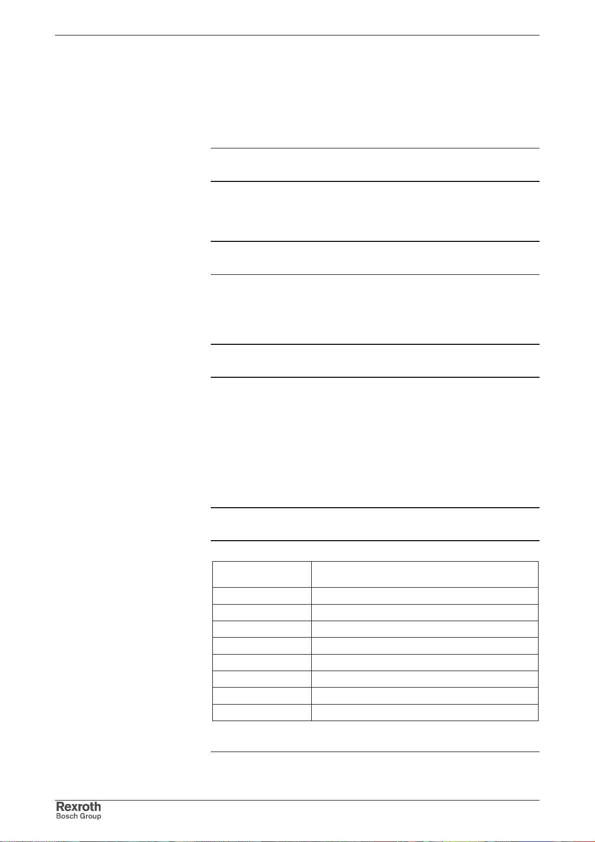
Errors are classified in dif ferent error classes. T here are 6 error classes
with different drive error reactions.
Note: The error class can be rec ognized by the diagnostic message
number.
Diagnostic message
number Error class
F2xxx non-fatal error
F3xxx non-fatal safety technology error
F4xxx interface error
F6xxx travel range error
F7xxx safety technology error
F8xxx fatal error
F9xxx fatal system error
E-xxxx fatal system error "processor exception"
Fig. 1-1: Overview of error classes
Note: Apart from the m entioned error classes that can occur during
operation, errors can occur when the devices are booted and
DOK-INDRV*-FU*********-IB01-EN-P
Page 11

Rexroth IndraDrive Introducing the Products 1-5
during firmware download. These er rors are not displayed at
the control panel with a diagnostic message number of the
"Fxxxx" pattern, but with a short text. Boot errors and firmware
download errors are separately described in the
documentation "Troubleshooting Guide" (diagnostic message
description).
Error Reactions of the Drive
Clearing Error Messages
Clearing Error Messages when
Drive Enable Was Set
If the drive controller is in control and an error status is detected, the
execution of a drive error reac tion is autom atically started. The diagnostic
message number "Fxxxx" flashes on the display of the control panel.
The drive reaction in the case of interface errors and non-fatal errors is
determined in parameter P-0-0119, Best possible deceleration At the
end of each error reaction, the drive is torque-free.
See also "Error Reactions" in chapter "Drive Functions"
Error messages are not cleared automatically but by the following action:
• activating the S-0-0099, C0500 Reset class 1 diagnostics command
- or -
• actuating the "Esc" button on the control panel
If the error status persists the error message is immediately generated
again.
If a drive error occurs while operating with drive enable having been set,
the drive carries out an error reaction. T he drive autom atically deactivates
itself at the end of each error reaction; in other words, the output stage is
switched off and the drive switches f rom an energized to a de-energized
state.
To reactivate the drive:
• clear the error message and
• input a positive edge for drive enable again.
Error Memory
The diagnostic message numbers of occurring errors are written to an
error mem ory. This m em ory contains the diagnostic m es sage num bers of
the last 50 errors that occurred and the time when they occurred. Er rors
caused by a shutdown of the control voltage (e.g. F8070 +24Volt DC
error) are not stored in the error memory.
The diagnostic mess age num bers in the er ror m em or y are mapped to the
P-0-0192, Diagnostic numbers of error memory parameter and can be
displayed by means of the control panel. By means of the "IndraWork s D"
commissioning tool it is possible to display the diagnostic message
numbers and the respective times at which the errors occurred.
DOK-INDRV*-FU*********-IB01-EN-P
Page 12

1-6 Introducing the Products Rexroth IndraDrive
1.2 Rexroth IndraDrive Hardware Platform
Drive Controllers
Overview
The drive controller consists of two essential parts:
• power section
• control section
Power section
Control section
300 mm Design
The power section incorporates the c ontrol section and has the following
connections:
• mains voltage connection (at supply modules and HCS devices)
• motor connection (with optional motor holding brake and motor
temperature monitor)
• 24 V control voltage
• DC bus connection
• module bus connection
• connection for external braking resistor (at HCS devices)
The control section is a separate component that is plugged into the
power section. The drive controller is supplied complete with factoryinstalled (possibly configured) control section.
Power Sections
IndraDrive C
• HCS02.1E-W0012
• HCS02.1E-W0028
• HCS02.1E-W0054
• HCS02.1E-W0070
400 mm Design
• HCS03.1E-W0070
• HCS03.1E-W0100
• HCS03.1E-W0150
• HCS03.1E-W0210
Control Sections
• BASIC OPENLOOP (single axis; type CSB01.1N-FC-…)
• BASIC PROFIBUS (single axis CSB01.1N-PB-…)
Supported Control Section Configurations
The configurable control sections differ with regard to the scope of their
configurability. It basically depends on the control section type and the
corresponding firmware variant. The following abbreviations are used:
Options for master communication:
• PB → PROFIBUS-DP
• FC → FC Interface
DOK-INDRV*-FU*********-IB01-EN-P
Page 13
Rexroth IndraDrive Introducing the Products 1-7
Motors and Measuring Systems
Supported Motors
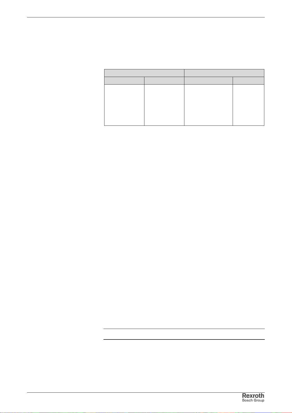
The table below contains an overview of the Rexroth motors which can be
operated at IndraDrive controllers.
Housing motors Kit motors
synchronous asynchronous synchronous asynchr.
Third party motors
Motor Encoders and External
Optional Encoders
MHD
MKD
MKE
MSK (IndraDyn S)
MAL
SF (Bosch)
Fig. 1-2: Appropriate Rexroth motors for IndraDrive
2AD
ADF
MAD (IndraDyn A)
MAF (IndraDyn A)
MLF (IndraDyn L)
MBS (Standard)
MBSxx2 (IndraDyn H)
MBT (IndraDyn T)
LSF
1MB
Third party motors must meet the specified requirements.
Supported Measuring Systems
In addition to the encoders integrated in the Rexroth motors, the
IndraDrive firmware can evaluate the following measuring systems as
motor encoders or as external optional control encoders:
• Bosch Rexroth GDS or GDM encoders (single-turn or multi-turn type)
• resolvers according to Rexroth signal specification (single-turn or
multi-turn type)
pp
)
pp
)
)
pp
• encoders with sine signals and EnDat2.1 interface (1 V
• encoders with sine signals (1 V
pp
)
• encoders with square-wave signals (TTL)
• Hall sensor box and encoder with sine signals (1 V
• Hall sensor box and encoder with square-wave signals (TTL)
• encoders with sine signals and HIPERFACE interface (1 V
Measuring Encoders
For measuring purposes the firmware can evaluate the following
measuring systems (measuring encoders, no control encoders):
• Bosch Rexroth GDS or GDM encoders (single-turn or multi-turn type)
• encoders with sine signals and EnDat2.1 interface (1 V
• encoders with sine signals (1 V
pp
)
pp
)
• encoders with square-wave signals (TTL)
• encoders with sine signals and HIPERFACE interface (1 V
pp
)
• motor encoders of MSK, MHD, 2AD, ADF, MAD, MAF motors
• SSI encoders
Note: Resolvers cannot be evaluated as measuring encoders!
DOK-INDRV*-FU*********-IB01-EN-P
Page 14
1-8 Introducing the Products Rexroth IndraDrive
Master Communication
PROFIBUS Interface
General Features
• cyclic data exchange of command and actual value (max. 32 byte
each direction; min. cycle time of 500 µs)
• parameter channel for parameterization and diagnosing via field bus
• safe process data channel (PROFIsafe), optional
• free configuration of telegram contents possible (many cyclic
configurable parameter IDN)
1.3 Rexroth IndraDrive Firmware Platform
Type Code
Structure of the Firmware Type
Designation
IndraDrive-Firmware
Basic single-axis
FWA-INDRV*
Firmware Types That Can Be
Ordered
Control
section
Basic
single-axis
Firmware
range
FWA-INDRV*- MPB- 04 VRS- D5- 0- NNN -NN base package (open-loop)
FWA-INDRV*- MPB- 04 VRS- D5- 0- SNC -NN base package (open-loop) + synchronization
FWA-INDRV*- MPB- 04 VRS- D5- 0- MSP -NN base package (open-l oop) + main spindle
FWA-INDRV*- MPB- 04 VRS- D5- 0- ALL -NN base package (open-loop) + all altern. functions
FWA-INDRV*- MPB- 04 VRS- D5- 0- NNN -ML base package (open-loop) + IndraMotion MLD-S
FWA-INDRV*- MPB- 04 VRS- D5- 0- *** -ML
FWA-INDRV*- MPB- 04 VRS- D5- 1- NNN -NN base package (closed-loop)
FWA-INDRV*- MPB- 04 VRS- D5- 1- SRV -NN base package (cl osed-loop) + servo function
FWA-INDRV*- MPB- 04 VRS- D5- 1- SNC -NN base package (closed-loop) + synchroni zat i on
FWA-INDRV*- MPB- 04 VRS- D5- 1- MSP -NN base package (closed-loop) + main spindle
FWA-INDRV*- MPB- 04 VRS- D5- 1- ALL -NN base pack age (closed-loop) + all altern. functions
FWA-INDRV*- MPB- 04 VRS- D5- 1- NNN -ML base package (closed-l oop) + IndraMotion MLD-S
FWA-INDRV*- MPB- 04 VRS- D5- 1- *** -ML
Base
package
The individual functional packages can be com bined to for m the f ollowing
firmware types that can be ordered:
Base package of
variant …
(depending on
control section)
-MPB-
Version
04 VRS- D5- x- xxx- xx
Release
Language
Open-/closed-
loop
Alternative
expansion
packages
Additive
expansion
Fig. 1-3: Basic structure of the firmware type designation
The following overview shows the available scope of functions of the
respective base package:
Version
Release
Language
Open/closed-
loop
Alternative
functional
packages
IndraMotion
MLD-S
Scope of functional packages
base package (open-loop) + *** + IndraMotion MLD-S
base package (closed-loop) + *** +
*** selected option "alternative functional packages" according to
availability
Fig. 1-4: Overview of firmware types and functional packages they are
containing
IndraMotion MLD-S
packages
DOK-INDRV*-FU*********-IB01-EN-P
Page 15

Rexroth IndraDrive Introducing the Products 1-9
Functions Overview
Supported Operating Modes
The drive firmware supports the following operating modes:
• torque/force control
• velocity control
• position control with cyclic command value input
• drive-internal interpolation
• drive-controlled positioning
• positioning block mode
• synchronization modes:
• velocity synchronization with real/virtual master axis
• phase synchronization with real/virtual master axis
• electronic cam shaft with real/virtual master axis
• electronic motion profile with real/virtual master axis
Note: The operating modes supported by the firmware depend on
the hardware and firmware and are contained in parameter
S-0-0292, List of all operating modes.
Drive Functions
These are the most important drive functions of the MPX-04 firmware:
• Drive Halt
• establishing the position data reference
• drive-controlled homing
• setting absolute measuring
• shifting the position data reference
• drive error reactions
• best possible deceleration
• package reaction on error
• NC reaction on error
• E-Stop function
• compensation functions/corrections
• friction torque compensation
• encoder correction
• axis error correction
• quadrant error correction
• spindle positioning
• drive-integrated command value generator
• parameter set switching
• probe function
• encoder emulation
• programmable position switch
• drive-integrated PLC (IndraMotion MLD-S)
• integrated safety technology
DOK-INDRV*-FU*********-IB01-EN-P
Page 16
1-10 Introducing the Products Rexroth IndraDrive
• monitoring functions
• limitations that can be parameterized
• output of control signals
• numerous diagnostic possibilities
• drive-internal generation of diagnostic messages
• analog output
• status displays, status classes
• oscilloscope function
• monitoring function
• patch function
• code of optional card
• parameter value check
• operating hours counter, logbook function, error memory
Performance Data
Overview
For the control performance of the IndraDrive range we basically
distinguish three levels with regard to the clock rates (cycle times):
• Basic performance
→ standard control performance by medium internal clock rates for the
control loops and the signal processing of inputs/outputs or driveintegrated PLC (IndraMotion MLD-S)
In this documentation the clock rate data refer to the following
characteristic values:
• current loop clock T
• velocity loop clock T
• position loop clock T
• cycle time of PLC (IndraMotion MLD-S) T
• cycle time of master communication T
A_current
A_velocity
A_position
MLD-S
MastCom
Control
section type/
firmware
CSB01.1/MPB
Functional
packages
all, except for
"synchronization" and
"IndraMotion"
Perform.
level
Basic
Basic
The table below contains an overview of the clock rates depending on the
respective control performance. The detailed assignment of the c lock rate
to control section design, performance level and parameter setting is
contained in the table in section "Control Section Design and
Performance" (see below).
Performance
Basic
Fig. 1-5: Clock rates (depending on the available performance)
T
A_currentTA_velocityTA_posit.TMLD-STMastCom
125 µs 250 µs 500 µs
125 µs 250 µs 500 µs
1)
: can be set via P-0-0001
P-0-0556: config word of axis controller
Fig. 1-6: Performance depending on the control section design
T
A_Strom
T
A_Geschw
T
A_Lage
T
MLD-S
T
FKM
62,5/83,3/125 µs 250 µs 500 µs 2000 µs 500/1000 µs
Switching
frequency
--
1000 µs
--
1000 µs
4000 Hz 0 0
8000 Hz 0 0
P-0-0556
1)
bit 2 bit 5
DOK-INDRV*-FU*********-IB01-EN-P
Page 17

Rexroth IndraDrive Introducing the Products 1-11
Selecting Performance via
Parameter P-0-0556
Restricted Performance with
Certain Functional Packages
For certain applications it is neces sary to use the same clock rates in all
axes so that the slowest drive sets the clock. It is therefore possible to
specifically reduce the performance via bit 2 and bit 5 of parameter
P-0-0556, Config word of axis controller.
• For BASIC control sections it is possible to select the perf ormance
levels "Basic" or "Economy" via bit 5 of P-0-0556.
See also Parameter Description "P-0-0556, Config word of axis controller"
Note: The effective clock rates of the active performance level are
contained in the table "Performance depending on the control
section design" in section "Control Section Design and
Performance" (see above).
If you use extensive and complex functions, the internal clock rates for
BASIC control sections (CSB with firmware MPB and CDB with
firmware MPD) are automatically reduced. This applies to the us e of the
following functional packages:
• drive-integrated PLC "IndraMotion MLD-S" (functional package "ML")
• expansion package "synchronization" (functional package "SNC")
If you use one of these functional packages for BASIC control s ections,
the clock rates (position loop, velocity loop) are reduced to the lowest
performance level "Economy!"
DOK-INDRV*-FU*********-IB01-EN-P
Page 18
1-12 Introducing the Products Rexroth IndraDrive
1.4 Rexroth IndraDyn Motors
Housing Motors
Type Code S
Example
Product
MSK 030 B 0900 NN S1 U G 0 NNNN
Motor size
Motor length
MSK030B-0900-NN-S1-UG0-NNNN
Windings code
Fig. 1-7: Basic structure of type code
Housing design
Encoder
Electrical
Connection
Shaft
Holding brake
Other design
Type Code IndraDyn A
Example
MAF130B-0150-FQ-M0-LH0-05-N1
Product
MAF 130 B 0150 FQ M0 L H 0 05 N 1
Motor size
Motor length
Windings code
Cooling mode
Fig. 1-8: Basic structure of type code
Encoder
Electrical Connection
Shaft
Holding brake
Mounting style
Bearings
Kit Motors
Type Code IndraDyn L
Example
Product
MLP 100 A 0120 F S N0 CN NNNN
Motor size
MLP100A-0120-FS-N0CN-NNNN
Motor length
Fig. 1-9: Basic structure of type code
Windings code
Cooling mode
Encapsulation
Encoder
Electrical
Connection
Vibration severity
grade
Other design
DOK-INDRV*-FU*********-IB01-EN-P
Page 19
Rexroth IndraDrive Introducing the Products 1-13
Type Code IndraDyn H
Example 1
Product
MRS 102 B 1N 0046 NNNN
Product
MSS 102 B 0800 F A N0 CN NNNN
Motor size
Motor size
Example 2
MRS102B-1N-0046-NNNN
Motor length
Fig. 1-10: Basic structure of type code
MSS102B-0800-FA-N0CN-NNNN
Motor length
Fig. 1-11: Basic structure of type code
Windings code
Cooling mode
Mounting style
Cooling
connector
Internal diameter
of the rotor
Encoder
Electrical
connection
Other design
Other design
1.5 Third-Party Motors at IndraDrive Controllers
General Information on Third-Par ty Motors
Why Use Third-Party Motors at IndraDrive?
Today machine axes are mainly moved with electric drives. Motors of
standard design are used in most cases as this is the most cost-ef ficient
solution.
Special Requirements
Undeliverable Motor Design
Check Before Using Third-Party
Motors
Additional Aspects to be
Observed
Due to special requirements at machine axes, constructional or safetyrelated aspects, it may be necessary for the m achine manufacturer to us e
a motor construction diverging from the standard.
For these cases there is the demand on the drive supplier to realize, apart
from the deliverable standard drive consisting of (standard) motor,
controller, cable and, if required, m achine control unit, drives with motors
that are not included in his own product range due to the special design.
At Rexroth controllers of the IndraDrive range it is also possible to use
third-party motors. For this purpose, check whether the third-party motor
complies with the requirements of use.
Which are the Important Directives?
According to the legal requirements
• of the EU directives EMC89/336/EEC and
• the German EMC laws
installations and machines have to be designed and built according to the
present state of standardization. In order to comply with the machine
directives regarding "electromagnetic compatibility (EMC)", a conformity
test of the drive system (motor with controller and connection design) has
DOK-INDRV*-FU*********-IB01-EN-P
Page 20

1-14 Introducing the Products Rexroth IndraDrive
to be carried out. The test of the drive system and com pliance with the
directives have to be guaranteed by the machine manufacturer.
Third-Party Motors to be Controlled
Motor Types
The following motor types can be controlled:
• asynchronous motors, rotary
• asynchronous motors, linear
• synchronous motors, rotary
• synchronous motors, linear
These motors c an be operated within the scope of the technical data of
the selected IndraDrive controller. If motors have been provided with a
holding brake, it should be controlled via the controller. Make sure that the
relevant technical data of the motor holding brake are complying with
those of the holding brake output.
Note: For third-party motors Bosch Rexroth, as a m atter of principle,
does not assume the guarantee for the power data at the
motor shaft!
Synchronous Motors
In the case of synchronous motors, the com mutation off set has to be set
during commiss ioning. The drive firmware provides several methods for
determining this offset so that it is possible to determine the value for
different motor characteristics.
Note: Observe the restrictions in conjunction with the commutation
offset determination when using synchronous motors!
See Functional Description of firmware "Motor Control:
Commutation Setting" in chapter "Drive Control"
Possibly available reluctance property cannot be used for synchronous
third-party motors! For third-party motors it is impossible to determine f ailsafe motor parameter values for using the reluctance property; the
respective bit of P-0-4014, Type of construction of motor therefore
mustn't be set!
Requirements on Third-Party Motors
For successful and fail-safe use of a third-party motor check
• whether the third-party motor to be controlled satisfies the voltage
loads,
• which controller, including supply, is suitable due to the motor power to
be delivered,
• whether the third-party motor has the required minimum inductance,
• whether the motor can be protected against inadm issible temperature
rise in the case of overload (temperature evaluation),
• whether the mounted position measur ing system can be evaluated by
the controller or which position measuring system can be selected for
kit motors.
Voltage Load of the Third-Party Motor
The voltage load of the insulation system of a motor oc curring in prac tical
application is mainly influenced by the following characteristics:
• The output variables of the drive controller which is used (feed the
transmission distance).
DOK-INDRV*-FU*********-IB01-EN-P
Page 21

Rexroth IndraDrive Introducing the Products 1-15
• The cable parameters depending on cable design and length
(determine the properties of the transmission distance, such as the
attenuation).
• The motor design regarding c apacitive and inductive properties (form
the end of the transmission distance).
As a result of the variables, the insulation system of the third-par ty motor,
as regards voltage, is loaded by the values
• peak voltage U
pp
and
• voltage change dv/dt.
The occurring peak voltages at the motor are caused by reflections in the
motor cable. The insulation of the motor is thereby loaded with other peak
voltages and voltage changes than the ones occurr ing at the output of the
power section.
Note: Determine the occurring voltage load at the terminals of the
third-party motor in the application with all involved
components.
Use of Voltage-Reducing
Components, Motor Filter HMF
Use voltage-reducing components (e.g. motor filter HMF), if one of the
following criteria applies:
• allowed voltage change (dv/dt) of third-party motor smaller than
5 kV/µs
• allowed peak voltage (crest value) of third-par ty motor between phas ephase and phase-housing smaller than 1500 V
• motor cable length smaller than 25 m
• mains voltage greater than AC440V
Note: Apart from the nominal current IN, especially take the
maximum allowed switching frequency of the power output
stage (f
) into account with which the motor filter HMF m ay be
s
operated.
Verify the success of the voltage-reducing measure.
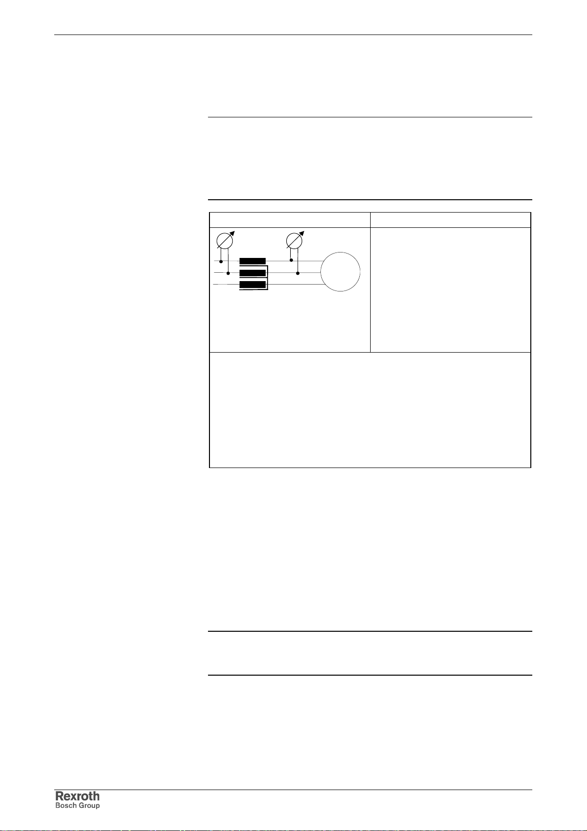
Minimum Inductance of Third-Party Motor
Depending on the controller used, the motor has to have a minimum
value for inductance. The actually available inductance of a motor c an be
measured directly between two motor terminals by means of an
inductance measuring bridge. The measurement has to be made for a
complete motor wired f or normal operation but not yet connected. Dur ing
the measurement one motor terminal remains open!
For asynchronous motors the measured value can only be used if the
rotor doesn't have closed slots!
DOK-INDRV*-FU*********-IB01-EN-P
Controller type Minimum required motor inductance
HCS with 3*AC230V
HMS, HMD at HMV (3*AC400V)
HMS, HMD at HCS (3*AC400V)
HMS, HMD at HMV (3*AC480V)
HMS, HMD at HCS (3*AC480V)
I
: maximum controller current acc. to type code (rms value)
Typ
f
: desired switching frequency in kHz
s
Fig. 1-12: Minimum inductances depending on controller data, supply units and
supply voltage
L
= 60* 4/(√2 * I
U-V
L
= 80* 4/(√2 * I
U-V
L
= 116* 4/( √
U-V
* fs)(in mH)
Typ
* fs)(in mH)
Typ
2 *
I
* fs) (in mH)
Typ
Page 22
1-16 Introducing the Products Rexroth IndraDrive
V
Use a three-phase choke in the motor feed wire, if the inductance of the
third-party motor is smaller than indicated in the table above. T his choke
has to increase the inductance that can be measur ed between two motor
terminals to the minimum value.
Note: When the inductanc e is measured, diff erent induc tanc e values
can be determined at differ ent rotor positions within one pole
pair distance of the motor . The average value is relevant for
the check of the minimum value.
Correct values can only be determined when the motor is in
standstill!
Available third-party motor Planned third-party motor
Calculating the leakage inductance
(asynchronous motor) or inductance
(synchronous motor) of the third-party
motor by means of the single-phase
equivalent circuit diagram
(manufacturer's specification!).
Determine choke by means of
calculation, if necessary.
It is recommended to contact Rexroth!
- L
U-V
L
U-V
U
Motor
W
)
L
U-Vmin
3x L
LDr = 0,5 * (L
Dr
U-Vmin
(inductance measurement with 1 kHz)
mounting of 3x L
(three-phase choke)
Dr
Requirements on the choke:
-I
≥ I
n_Dr
n_Mot
The rated current of the choke has to be greater than or equal to
the rated motor current.
- Depending on the maximum speed, the choke is loaded with the respective
output frequency and the PWM frequency of the controller.
- The insulation class has to correspond at least to that of the motor or
has to be dimensioned for higher temperatures.
- The voltage load of the choke depends on the controller used.
Fig. 1-13: Data for possibly required choke
Temperature Evaluation of Third-Party Motor
Only operate such motors with incorporated temperature sensor at
IndraDrive controllers so that the m otor can be ther mally monitored by the
controller and protected against destruction by too high temperatur e rise
(see P-0-0512, Temperature sensor).
When, in exceptional cases, you want to operate third-party motors
without temperature sensor at IndraDrive contr ollers, you must determ ine
the thermal time constants of motor housing (P-0-4035) and motor
winding (P-0-4034, P-0-4037). The firmware-internal motor temperature
model can thereby reflect the cooling situation of the motor correctly.
Note: In case the motor housing or blower is dirty, this worsens the
cooling situation of the motor and protection against thermal
overload is therefore insufficient!
DOK-INDRV*-FU*********-IB01-EN-P
Page 23
Rexroth IndraDrive Introducing the Products 1-17
Requirements on the Encoder of the Third-Party Motor
Motor Encoder of Asynchronous Third-Party Motor
Asynchronous motors can also be controlled by IndraDrive controllers in
"open-loop" operation (without motor encoder). In "closed-loop" operation
(with motor encoder) a relative measuring system is sufficient for
asynchronous motors.
Motor Encoder of Synchronous Third-Party Motor
For fail-safe drives with synchronous third-party motors at IndraDrive
controllers the following possible com binations or restrictions have to be
taken into account when selecting the measuring system:
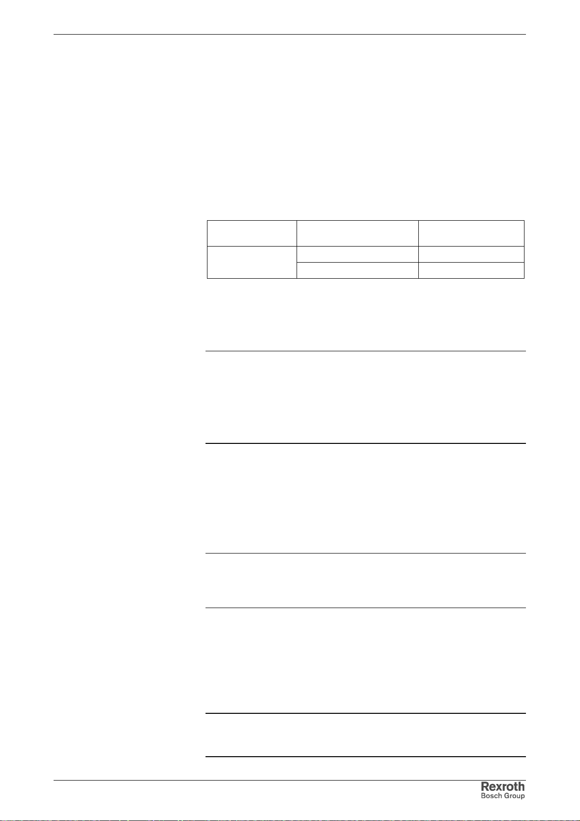
Drive range Motor measuring system Synchronous third-
party motor
IndraDrive
+ … advantageous combination
o … Combination is possible (restrictions specific to application),
commissioning may be more complicated!
Fig. 1-14: Possible combinations of synchronous third-party motor and motor
measuring system
absolute +
relative o
Note: The control section integrated in the controller can evaluate
measuring systems as a m otor encoder if they are contained
in P-0-0074, Encoder type 1 (motor encoder) (see also
Project Planning Manual of the IndraDrive control sections).
For information on absolute and relative measuring systems
see section "Measuring Systems" of Functional Description of
firmware!
Notes on Selection and Commissioning
Selecting the Controller as Regards Continuous Current
The controller required for the respective motor and the supply unit are
determined by comparing the motor data to the data of these devices (see
documentation for HMS/HMD and HMV or HCS).
Note: The continuous current of the controller should be greater than
that of the motor, the continuous power of the supply must be
greater than the sum of all average powers of the ax es of the
drive system!
Selecting the Connection Technique
The available power and encoder cables are described in the
documentation "Connection Cables; Selection Data" (DOK-CONNECCABLE*STAND-AU...).
DOK-INDRV*-FU*********-IB01-EN-P
Notes on Commissioning
Note: For further information, notes on commissioning and
supporting documents (e.g. forms for entering the required
data) see Functional Description of firmware.
Page 24
1-18 Introducing the Products Rexroth IndraDrive
1.6 Approval, Listing
Conformities
Declaration of Conformity
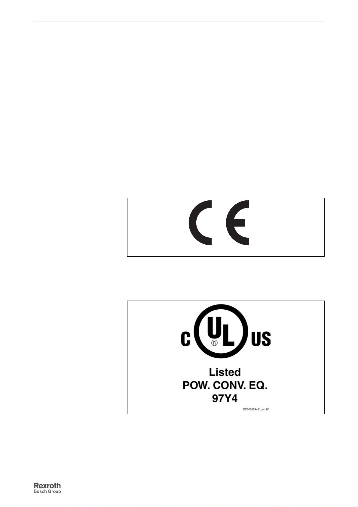
CE Label
For Rexroth IndraDrive components there are declarations of conformity
available. These declarations conf irm that the components are designed
according to valid EC directives. If required, you can ask your sales
representative for these declarations.
Low-Voltage Directive
The Rexroth products of a drive s ystem mentioned in this docum entation
comply with the requirements of the EC Directive 73/23/EEC (LowVoltage Directive), annex III B.
EMC Directive
The Rexroth products of a drive s ystem mentioned in this docum entation
comply with the requirements of the EC Directive 89/336/EEC (EMC
Directive) with the amendments 91/263/EEC and 93/68/EEC.
Fig. 1-15: CE label
CEf1.fh7
C-UL-US-Listing
Devices approved by the UL agency carry the following label:
Fig. 1-16: C-UL-US label
DOK-INDRV*-FU*********-IB01-EN-P
Page 25
Rexroth IndraDrive Introducing the Products 1-19
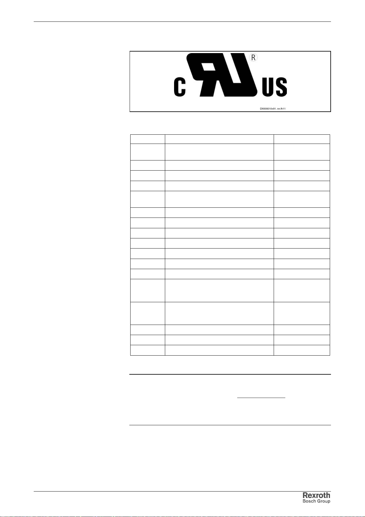
Motors approved by the UL agency carry the following label:
Fig. 1-17: C-UR-US label
C-UL-US Listed Components
Product Component File Number
HMS01.1N- W0020, W0036, W0054, W0070, W0150,
W0210
HMS02.1N- W0028, W0054 E 134201
HMD01.1N- W0012, W0020, W0036 E 134201
HCS02.1E- W0012, W0028, W0054, W0070 E 134201
HCS03.1E- W0070, W0100, W0150, W0210 Manufacturer REFU
HMV01.1E- W0030-A-07, W0075-A-07, W0120-A-07 E 134201
HMV01.1R- W0018-A-07, W0045-A-07, W0065-A-07 E 134201
HMV02.1R- W0015 E 134201
HLB01.1C- 01K0-N06R0-A-007-NNN E 134201
HLB01.1D- 02K0-N03R4-A-007-NNN E 134201
HLC01.1C- 01M0-A-007, 02M4-A-007 E 134201
HLC01.1D- 05M0-A-007 E 134201
NFD03.1- -007, -016, -030, -055, -075, -130, -180 E 172117 and CSA
HNL01.1- ..... CSA Cert.
HNF01.1 In preparation E 134201
HNK01.1 In preparation E 134201
HLR01.1 In preparation E 134201
E 134201
E254781
Cert. 1038841Master
Contr. 171321
1492099Master
Contr. 222887
DOK-INDRV*-FU*********-IB01-EN-P
Fig 1-18: C-UL-US listed Rexroth IndraDrive components
Note: The com ponents are lis ted by the file number of „Underwriters
Laboratories Inc.®" (UL). The doc umented evidence of listing
can be seen in the internet: http://www.ul.com, "Certif ications",
enter file number or "Company name: Rexroth.
The control sections are included in the listing of the power
sections. The control sections are not listed separately.
Page 26

1-20 Introducing the Products Rexroth IndraDrive
DOK-INDRV*-FU*********-IB01-EN-P
Page 27

Rexroth IndraDrive Important Directions for Use 2-1
2 Important Directions for Use
2.1 Appropriate Use
Introduction
Rexroth products represent state-of-the-art developments and
manufacturing. They are tested prior to delivery to ensure operating safety
and reliability.
The products may only be used in the manner that is defined as
appropriate. If they are used in an inappropriate manner, then situations
can develop that may lead to property damage or injury to personnel.
Note: Rexroth as manufacturer is not liable for any damages
resulting from inappropriate us e. In such cases , the guarantee
and the right to payment of damages resulting from
inappropriate use are forfeited. The user alone carries all
responsibility of the risks.
Before using Rexroth products, mak e sure that all the pre-requisites for
an appropriate use of the products are satisfied:
• Personnel that in any way, shape or form uses our pr oducts mus t first
read and understand the relevant safety instructions and be familiar
with appropriate use.
• If the products take the form of hardware, then they must remain in
their original state, in other words, no structural changes are permitted.
It is not permitted to decompile software products or alter source
codes.
• Do not mount damaged or faulty products or use them in operation.
• Make sure that the products have been installed in the manner
described in the relevant documentation.
DOK-INDRV*-FU*********-IB01-EN-P
Page 28

2-2 Important Directions for Use Rexroth IndraDrive
Areas of Use and Application
Drive controllers made by Bosch Rexroth are designed to control
electrical motors and monitor their operation.
Control and monitoring of the motors may require additional sensor s and
actors.
Note: The drive controllers m ay only be used with the accessories
and parts specified in this document. If a com ponent has not
been specifically named, then it may not be either m ounted or
connected. The same applies to cables and lines.
Operation is only permitted in the specified configurations and
combinations of com ponents using the software and f irmware
as specified in the relevant Functional Descriptions.
Every drive controller has to be programmed before commissioning,
making it possible for the motor to execute the specific functions of an
application.
The drive controllers have been developed for use in single- and multiaxis drive and control tasks.
To ensure an application-specific use, the drive contr ollers are available
with different drive power and different interfaces.
Typical applications of the drive controllers include:
• handling and mounting systems,
• packaging and food machines,
• printing and paper processing machines and
• machine tools.
The drive controllers may only be operated under the assembly and
installation conditions described in this documentation, in the specified
position of normal use and under the ambient conditions as described
(temperature, degree of protection, humidity, EMC, etc.).
2.2 Inappropriate Use
Using the drive controllers outside of the operating conditions described in
this documentation and outside of the indicated technical data and
specifications is defined as "inappropriate use".
Drive controllers must not be used, if
• ... they are subject to operating conditions that do not meet the
• Furthermore, the drive controllers must not be used in applications
• Please car efully follow the specific ations outlined in the general Saf ety
specified ambient conditions. This includes, for example, operation
under water, under extreme temperature f luctuations or extr emely high
maximum temperatures.
which have not been expressly authorized by Rexroth.
Instructions!
DOK-INDRV*-FU*********-IB01-EN-P
Page 29
Rexroth IndraDrive Safety Instructions for Electric Drives and Controls 3-1
3 Safety Instructions for Electric Drives and Controls
3.1 General Information
Using the Safety Instructions and Passing them on to Others
Do not attempt to install or com m iss ion this device without firs t reading all
documentation provided with the product. Read and understand these
safety instructions and all user documentation prior to working with the
device. If you do not have the user documentation for the device, contact
your responsible Bosch Rexroth sales representative. Ask for these
documents to be sent immediately to the person or pers ons responsible
for the safe operation of the device.
If the device is resold, rented and/or passed on to others in any other
form, then these safety instructions must be delivered with the device.
Improper use of these devices, failure to follow
the safety instructions in this document or
tampering with the product , i ncluding disabling
WARNING
of safety devices, may result in material
damage, bodily harm, electric shock or even
death!
Instructions for Use
Read these instructions before the initial startup of the equipment in order
to eliminate the risk of bodily harm or material damage. Follow these
safety instructions at all times.
• Bosch Rexroth AG is not liable for damages resulting fr om failure to
observe the warnings provided in this documentation.
• Read the operating, maintenance and safety instructions in your
language before starting up the mach ine. If you find that you cannot
completely understand the documentation for your product, please ask
your supplier to clarify.
• Proper and correct transport, storage, assembly and installation as
well as care in operation and maintenance are prerequisites for
optimal and safe operation of this device.
• Only assign trained and qualified persons to work with electrical
installations:
Only persons who are trained and qualified for the use and
operation of the device may work on this device or within its
proximity. The persons are qualified if they have sufficient
knowledge of the assembly, installation and operation of the
equipment as well as an understanding of all warnings and
precautionary measures noted in these instructions.
Furthermore, they must be trained, instructed and qualified to
switch electrical circuits and devic es on and off in accordance
with technical safety regulations, to ground them and to mark
them according to the requirements of safe work practices.
They must have adequate safety equipment and be trained in
first aid.
• Only use spare parts and accessories approved by the manufacturer.
• Follow all safety regulations and requirements for the specific
application as practiced in the country of use.
DOK-INDRV*-FU*********-IB01-EN-P
Page 30

3-2 Safety Instructions for Electric Drives and Controls Rexroth IndraDrive
• The devices have been designed for installation in industrial
machinery.
• The ambient conditions given in the product documentation must be
observed.
• Only use safety-relevant applications that are clearly and explicitly
approved in the Project Planning Manual. If this is not the case, they
are excluded.
Safety-relevant are all such applications which can cause danger to
persons and material damage.
• The info rmation given in the docum entation of the product with regard
to the use of the delivered components contains only examples of
applications and suggestions.
The machine and installation manufacturer must
make sure that the delivered components are suited for his
individual application and check the information given in this
documentation with regard to the use of the components,
make sure that his application complies with the applicable safety
regulations and standards and carry out the r equired measures,
modifications and complements.
• Startup of the delivered components is only permitted once it is sure
that the machine or installation in which they are installed complies
with the national regulations, safety specifications and standards of the
application.
• Operation is only permitted if the national EMC regulations for the
application are met.
• The instructions for installation in accor dance with EMC requirements
can be found in the documentation "EMC in Drive and Control
Systems".
• The machine or installation manufacturer is responsible for
compliance with the limiting values as prescribed in the national
regulations.
• Technical data, connections and operational conditions are specified in
the product documentation and must be followed at all times.
DOK-INDRV*-FU*********-IB01-EN-P
Page 31
Rexroth IndraDrive Safety Instructions for Electric Drives and Controls 3-3
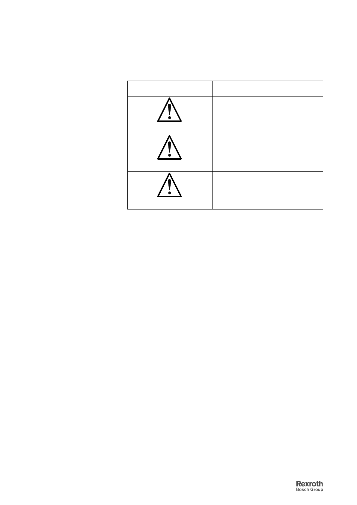
Explanation of Warning Symbols and Degrees of Hazard Seriousness
The safety instructions describe the following degrees of hazard
seriousness. The degree of hazard seriousness informs about the
consequences resulting from non-compliance with the safety instructions:
Warning symbol with signal
word
Degree of hazard seriousness according
to ANSI Z 535
Death or severe bodily harm will occur.
DANGER
Death or severe bodily harm may occur.
WARNING
Bodily harm or material damage may occur.
CAUTION
Fig. 3-1: Hazard classification (according to ANSI Z 535)
DOK-INDRV*-FU*********-IB01-EN-P
Page 32
3-4 Safety Instructions for Electric Drives and Controls Rexroth IndraDrive
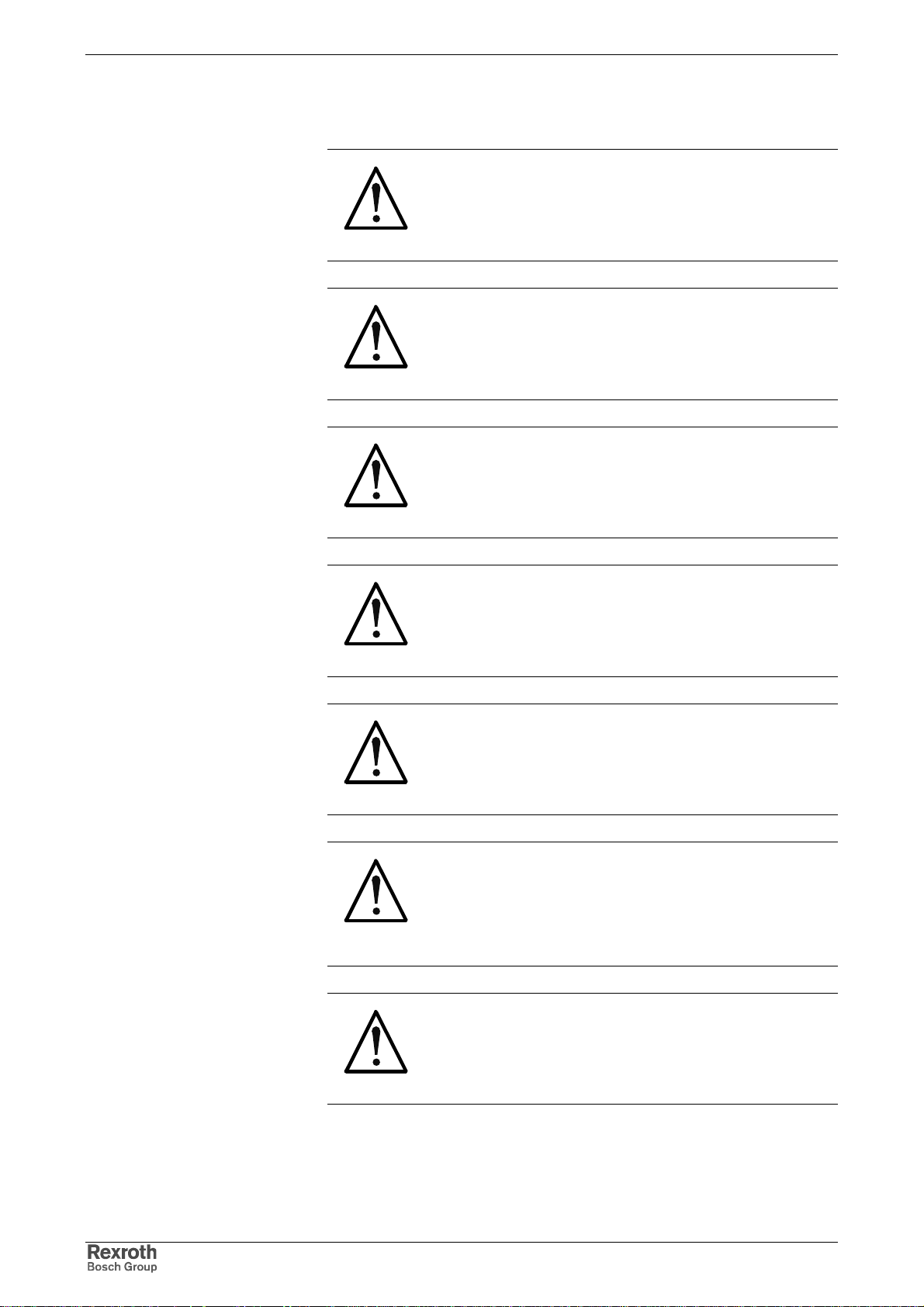
Hazards by Improper Use
High electric voltage and high worki ng current!
Risk of death or severe bodily injury by electric
shock!
DANGER
Dangerous movements! Danger to life, severe
bodily harm or material damage by
unintentional motor movements!
DANGER
High electric voltage because of incorrect
connection! Risk of death or bodily injury by
electric shock!
WARNING
WARNING
CAUTION
CAUTION
Health hazard for persons with heart
pacemakers, metal implants and hearing aids in
proximity to electrical equipment!
Hot surfaces on device housing! Danger of
injury! Danger of burns!
Risk of injury by improper handling! Risk of
bodily injury by bruising, shearing, cutting,
hitting, or improper handling of pressurized
lines!
Risk of injury by improper handling of batteries!
CAUTION
DOK-INDRV*-FU*********-IB01-EN-P
Page 33
Rexroth IndraDrive Safety Instructions for Electric Drives and Controls 3-5
3.2 Instructions with Regard to Specific Dangers
Protection Against Contact with Electrical Parts
Note: This section only concerns devices and drive com ponents with
voltages of more than 50 Volt.
Contact with parts conducting voltages above 50 Volts can cause
personal danger and electric shock. W hen operating electrical equipm ent,
it is unavoidable that some parts of the devices conduct dangerous
voltage.
High electrical voltage! Danger to life, electric
shock and severe bodily injury!
⇒
Only those trained and qualified to work with or on
DANGER
electrical equipment are permitted to operate,
maintain and repair this equipment.
⇒
Follow general construction and safety regulations
when working on electrical power installations.
⇒
Before switching on the device, the equipment
grounding conductor must have been nondetachably connected to all electrical equipment in
accordance with the connection diagram.
⇒
Do not operate electrical equipment at any time,
even for brief measurements or tests, if the
equipment grounding conductor is not permanently
connected to the mounting points of the com ponents
provided for this purpose.
⇒
Before working with electrical parts with voltage
potentials higher than 50 V, the device must be
disconnected from the mains voltage or power
supply unit. Provide a safeguard to prevent
reconnection.
⇒
With electr ical drive and filter components, obser ve
the following:
Wait 30 minutes after switching off power to allow
capacitors to discharge before beginning to work.
Measure the voltage on the capacitors before
beginning to work to make sure that the equipment is
safe to touch.
⇒
Never touch the electrical connection points of a
component while power is turned on.
⇒
Install the covers and guards provided with the
equipment properly before switching the device on.
Before switching the equipment on, cover and
safeguard live parts safely to prevent contact with
those parts.
⇒
A residual-current-operated circuit-breaker or r.c.d.
cannot be used for electric drives! Indirect contact
must be prevented by other means, for exam ple, by
an overcurrent protective device according to the
relevant standards.
⇒
Secure built-in devices from direct touching of
electrical parts by providing an external housing, for
example a control cabinet.
European countries: according to EN 50178/ 1998,
DOK-INDRV*-FU*********-IB01-EN-P
Page 34
3-6 Safety Instructions for Electric Drives and Controls Rexroth IndraDrive
2
section 5.3.2.3.
USA: See National Electrical Code (NEC), National
Electrical Manufacturers' Assoc iation (NEMA), as well as
local engineering regulations. The operator m ust observe
all the above regulations at any time.
With electrical drive and filter components, observe the following:
High housing voltage and large leakage current!
Risk of death or bodily injury by electric shock!
⇒
Before switching on, the housings of all electrical
DANGER
equipment and motors must be connected or
grounded with the equipment grounding conductor to
the grounding points. This is also applicable before
short tests.
⇒
The equipment grounding conductor of the electrical
equipment and the units must be non-detachably
and permanently connected to the power supply unit
at all times. The leakage current is greater than
3.5 mA.
⇒
Over the total length, use copper wire of a cross
section of a minim um of 10 mm
grounding connection!
⇒
Before start-up, also in trial runs , always attach the
equipment grounding conductor or connect with the
ground wire. Otherwise, high voltages may occur at
the housing causing electric shock.
for this equipment
Protection Against Electric Shock by Protective Low Voltage (PELV)
All connections and terminals with voltages between 5 and 50 Volt at
Rexroth products are protective extra-low voltage systems which are
provided with touch guard according to the product standards.
High electric voltage by incorrect connection!
Risk of death or bodily injury by electric shock!
⇒
To all connections and terminals with voltages
WARNING
between 0 and 50 Volt, only devices, electrical
components, and conductors may be connected
which are equipped with a PELV (Protective ExtraLow Voltage) system.
⇒
Connect only voltages and circuits which are s afely
isolated from dangerous voltages. Safe isolation is
achieved for example by isolating transfor mers, saf e
optocouplers or battery operation without mains
connection.
DOK-INDRV*-FU*********-IB01-EN-P
Page 35

Rexroth IndraDrive Safety Instructions for Electric Drives and Controls 3-7
Protection Against Dangerous Movements
Dangerous movements can be caused by faulty control of connected
motors. Some common examples are:
• improper or wrong wiring of cable connections
• incorrect operation of the equipment components
• wrong input of parameters before operation
• malfunction of sensors, encoders and monitoring devices
• defective components
• software or firmware erro rs
Dangerous movements can occur immediately after equipment is
switched on or even after an unspecified time of trouble-free operation.
The monitoring in the drive components will normally be sufficient to avoid
faulty operation in the connected drives. Regarding personal safety,
especially the danger of bodily harm and material damage, this alone
cannot be relied upon to ensure complete safety. Until the integrated
monitoring functions becom e effective, it must be assum ed in any case
that faulty drive movements will occur. The extent of faulty drive
movements depends upon the type of control and the state of operation.
DOK-INDRV*-FU*********-IB01-EN-P
Page 36
3-8 Safety Instructions for Electric Drives and Controls Rexroth IndraDrive
Dangerous movements! Danger to life, risk of
injury, severe bodily harm or material damage!
⇒
For the above reasons, ensure personal safety by
DANGER
means of qualified and tested higher-level monitoring
devices or measures integrated in the installation.
They have to be provided for by the user according
to the specific conditions within the installation and a
hazard and fault analysis. The safety regulations
applicable for the installation have to be taken into
consideration. Unintended machine motion or other
malfunction is possible if s af ety devices are dis abled,
bypassed or not activated.
To avoid accidents, bodily harm and/or material
damage:
⇒
Keep free and clear of the machine’s range of
motion and moving parts. Possible measures to
prevent people from accidentally entering the
machine’s range of motion:
- use safety fences
- use safety guards
- use protective coverings
- install light curtains or light barriers
⇒
Fences and coverings must be strong enough to
resist maximum possible momentum.
⇒
Mount the emergency stop switch in the immediate
reach of the operator. Verify that the em er gency stop
works before startup. Don’t oper ate the device if the
emergency stop is not working.
⇒
Isolate the drive power connection by means of an
emergency stop circuit or use a safety related
starting lockout to prevent unintentional start.
⇒
Make sure that the drives are brought to a safe
standstill before accessing or entering the danger
zone.
⇒
Additionally secure vertical axes against falling or
dropping after switching off the m otor power by, for
example:
- mechanically securing the vertical axes,
- adding an external braking/ arrester/ clamping
mechanism or
- ensuring sufficient equilibration of the vertical
axes.
The standard equipment m otor brake or an external
brake controlled directly by the drive controller are
not sufficient to guarantee personal safety!
DOK-INDRV*-FU*********-IB01-EN-P
Page 37
Rexroth IndraDrive Safety Instructions for Electric Drives and Controls 3-9
⇒
Disconnect electrical power to the equipment using a
master switch and secure the switch against
reconnection for:
- maintenance and repair work
- cleaning of equipment
- long periods of discontinued equipment use
⇒
Prevent the operation of high-frequency, remote
control and radio equipment near electr onics circuits
and supply leads. If the use of such devic es cannot
be avoided, verify the system and the installation for
possible malfunctions in all possible positions of
normal use before initial startup. If necessary,
perform a special electromagnetic compatibility
(EMC) test on the installation.
Protection Against Magnetic and Electromagnetic Fiel ds During Operation and Mounting
Magnetic and electromagnetic fields generated by current-carrying
conductors and permanent magnets in motors represent a serious
personal danger to those with heart pacemakers, metal implants and
hearing aids.
WARNING
Health hazard for persons with heart
pacemakers, metal implants and hearing aids in
proximity to electrical equipment!
⇒
Persons with heart pacemakers and m etal implants
are not permitted to enter following areas:
- Areas in which electrical equipm ent and parts are
mounted, being operated or commissioned.
- Areas in which parts of motors with permanent
magnets are being stored, repaired or mounted.
⇒
If it is necessary for som ebody with a pacemaker to
enter such an area, a doctor must be cons ulted prior
to doing so. The interference im munity of present or
future implanted heart pacemakers dif f er s greatly, so
that no general rules can be given.
⇒
Those with metal implants or metal pieces, as well
as with hearing aids must consult a doctor before
they enter the areas described above. Otherwise
health hazards may occur.
DOK-INDRV*-FU*********-IB01-EN-P
Page 38
3-10 Safety Instructions for Electric Drives and Controls Rexroth IndraDrive
Protection Against Contact with Hot Parts
Hot surfaces at motor housings, on drive
controllers or chokes! Danger of injury! Danger
of burns!
⇒
CAUTION
Do not touch surfaces of device housings and
chokes in the proximity of heat sources! Danger of
burns!
⇒
Do not touch housing surfaces of m otors! Danger of
burns!
⇒
According to operating conditions, temperatures can
be higher than 60 °C, 140 °F during or after
operation.
⇒
Befor e accessing m otors after having s witched them
off, let them cool down for a sufficiently long time.
Cooling down can require up to 140 minutes!
Roughly estimated, the time required for cooling
down is five times the thermal time constant
specified in the Technical Data.
⇒
After switching drive controllers or chokes off, wait
15 minutes to allow them to cool down before
touching them.
⇒
Wear safety gloves or do not work at hot surfaces.
⇒
For certain applic ations, the manuf acturer of the end
product, machine or installation, according to the
respective safety regulations, has to take m easures
to avoid injuries caused by burns in the end
application. These measures can be, for example:
warnings, guards (shielding or barrier), technical
documentation.
DOK-INDRV*-FU*********-IB01-EN-P
Page 39
Rexroth IndraDrive Safety Instructions for Electric Drives and Controls 3-11
Protection During Handling and Mounting
In unfavorable conditions, handling and assembling certain parts and
components in an improper way can cause injuries.
Risk of injury by improper handling! Bodily
injury by bruising, shearing, cutting, hitting!
⇒
Observe the general construction and safety
CAUTION
regulations on handling and assembly.
⇒
Use suitable devices for assembly and transport.
⇒
Avoid jamming and bruising by appropriate
measures.
⇒
Always use suitable tools. Use special tools if
specified.
⇒
Use lifting equipment and tools in the correct
manner.
⇒
If necessary, use suitable protective equipment (for
example safety goggles, safety shoes, safety
gloves).
⇒
Do not stand under hanging loads.
⇒
Immediately clean up any spilled liquids because of
the danger of skidding.
Battery Safety
Batteries consist of active chemicals enclosed in a solid housing.
Therefore, improper handling can cause injury or damages.
Risk of injury by improper handling!
⇒
Do not attempt to reactivate low batteries by heating
or other methods (risk of explosion and
CAUTION
Note: Environmental protection and disposal! The batteries installed
in the product are considered dangerous goods during land,
air, and sea transport (risk of explosion) in the sense of the
legal regulations. Dispose of used batteries separate from
other waste. Observe the local regulations in the country of
assembly.
cauterization).
⇒
Do not recharge the batteries as this may cause
leakage or explosion.
⇒
Do not throw batteries into open flames.
⇒
Do not dismantle batteries.
⇒
Do not damage electrical parts installed in the
devices.
DOK-INDRV*-FU*********-IB01-EN-P
Page 40
3-12 Safety Instructions for Electric Drives and Controls Rexroth IndraDrive
Protection Against Pressurized Systems
According to the information given in the Project Planning Manuals,
motors cooled with liquid and com pr es sed air , as well as dr ive c ontroller s ,
can be partially supplied with externally fed, pressurized media, such as
compressed air, hydraulics oil, cooling liquids, and cooling lubricating
agents. In these cases, improper handling of external supply systems,
supply lines, or connections can cause injuries or damages.
Risk of injury by improper handling of pressurized
lines!
⇒
Do not attempt to disconnect, open, or cut
CAUTION
pressurized lines (risk of explosion).
⇒
Observe the respective manufacturer's operating
instructions.
⇒
Before dismounting lines, relieve pressure and
empty medium.
⇒
Use suitable protective equipment (for example
safety goggles, safety shoes, safety gloves).
⇒
Immediately clean up any spilled liquids from the
floor.
Note: Environmental protection and disposal! The agents used to
operate the product might not be economically friendly.
Dispose of ecologically harmful agents separate from other
waste. Observe the local regulations in the country of
assembly.
DOK-INDRV*-FU*********-IB01-EN-P
Page 41
Rexroth IndraDrive Identification, Transport, Storage, Installation Conditions 4-1
4 Identification, Transport, Storage,
Installation Conditions
4.1 Identification
Type Code
Firmware MPB-04
Control
section
Basic
single-axis
Firmware
range
FWA-INDRV*- MPB- 04 V RS- D5- 0- NNN -NN base pack age (open-l oop)
FWA-INDRV*- MPB- 04 V RS - D5- 0- SNC -NN base package (open-loop) + synchronization
FWA-INDRV*- MPB- 04 V RS - D5- 0- MSP -NN base package (open-loop) + mai n spindle
FWA-INDRV*- MPB- 04 V RS - D5- 0- ALL -NN base package (open-loop) + all al t ern. functions
FWA-INDRV*- MPB- 04 V RS - D5- 0- NNN -ML base package (open-loop) + IndraMotion MLD-S
FWA-INDRV*- MPB- 04 VRS- D5- 0- *** -ML
FWA-INDRV*- MPB- 04 VRS- D5- 1- NNN -NN base package (closed-loop)
FWA-INDRV*- MPB- 04 VRS- D5- 1- SRV -NN base package (cl osed-loop) + servo function
FWA-INDRV*- MPB- 04 VRS- D5- 1- SNC -NN base package (closed-loop) + synchronizati on
FWA-INDRV*- MPB- 04 VRS- D5- 1- MSP -NN base package (closed-loop) + main spindle
FWA-INDRV*- MPB- 04 VRS- D5- 1- ALL -NN base pack age (closed-loop) + all altern. functions
FWA-INDRV*- MPB- 04 VRS- D5- 1- NNN -ML base package (cl osed-loop) + IndraMotion MLD-S
FWA-INDRV*- MPB- 04 VRS- D5- 1- *** -ML
Base
package
Version
Release
Language
Open/closed-
loop
Alternative
functional
packages
IndraMotion
MLD-S
Scope of functional packages
base package (open-loop) + *** + IndraMotion MLD-S
base package (closed-loop) + *** +
IndraMotion MLD-S
Power Sections HCS
Examples
HCS02.1E-W0012-A-03-NNNV (with integrated 24V supply);
HCS03.1E-W0100-A-05-NNBV (with integrated brake transistor)
Product
Line
Design
Power supply
Cooling mode
Maximum current
Protection mode
Mains connecting
voltage
HCS 02 1 E W 0012 A 03 NNNV
Fig. 4-1: Basic structure of type code
DOK-INDRV*-FU*********-IB01-EN-P
Other design
Page 42
4-2 Identification, Transport, Storage, Installation Conditions Rexroth IndraDrive
Control Sections BASIC CSB01.1N
Example
Product
CSB 01 1 N FC NNN NNN NN C NN FW
Line
Design
CSB01.1.N-FC-NNN-NNN-NN-C-NN-FW
Configuration option
Fig. 4-2: Basic structure of type code
Master communication
Option 1
Option 2
Safety option
Display
Other design
Firmware
Additional Components
Mains Choke HNL
Example
HNL01.1E-0980-N0026-A-480-NNNN
(to be ordered extra)
Product
HNL 01 1 E 0980 N 0026 A 480 NNNN
Line
Design
Supply system
Fig. 4-3: Basic structure of type code
Nominal inductance
Additional option
Nominal current
Degree of protection
Mains connecting
voltage
Other design
Mains Filter HNF, HNK
Example
Product
HNF 01 1 A F240 R 0094 A 480 NNNN
HNK 01 1 A A075 E 0050 A 500 NNNN
Line
Design
HNF01.1A-F240-R0094-A-480-NNNN
EMC-area per
DIN 61800-3
Fig. 4-4: Basic structure of type code
Applications
Supply system
Nominal current
Degree of
protection
Mains connecting
voltage
Other design
DOK-INDRV*-FU*********-IB01-EN-P
Page 43
Rexroth IndraDrive Identification, Transport, Storage, Installation Conditions 4-3
Motor Filter HMF
Example
Product
HMF 01 1 A N 1K5 E 0070 A 500 NNNN
Line
Design
HMF01.1A-N1K5-E0070-A-500-NNNN
Mounting style
Fig. 4-5: Basic structure of type code
Filter class
Motor frequency
Switching frequency
Nominal current
Degree of protection
Voltage rating
Other design
Braking Resistor HLR
Example
HLR01.1N-1K08-N05R0-A-007-NNNN
Product
HLR 01 1 N 1K08 N 05R0 A 007 NNNN
Line
Design
Mounting style
Fig. 4-6: Basic structure of type code
Continuous output
Additional option
Resistance
Degree of protection
DC bus nominal
voltage
Other design
Accessories
HAS01.1
Example
Product
HAS 01 1 050 048 NN
Line
HAS01.1-050-048-NN
Design
Fig. 4-7: Basic structure of type code
Device width
Bus-bar
Other design
DOK-INDRV*-FU*********-IB01-EN-P
Page 44
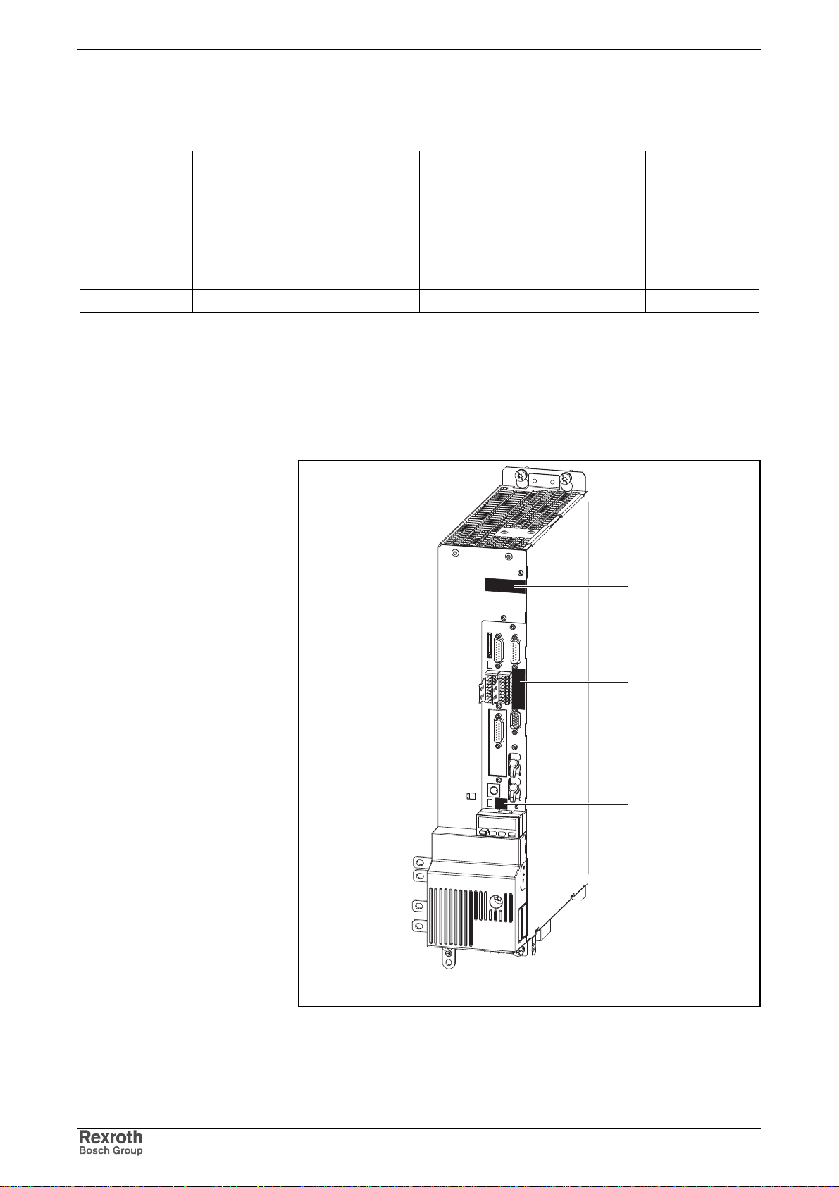
4-4 Identification, Transport, Storage, Installation Conditions Rexroth IndraDrive
HAS02.1
Product
HAS 02 1 001 NNN NN
Type Plates
Example
Line
HAS02.1-001-NNN-NN
Design
Fig. 4-8: Basic structure of type code
Device assignment
Other feature
Each drive component is marked by a type designation.
There is a type plate attached to all devices.
Type Plates at the Drive Controller
Other design
1: Power section type plate
2: Control section type plate
3: Firmware type plate
Fig. 4-9: Type plates at the drive controller
1
2
3
DG000023v01_nn.FH9
DOK-INDRV*-FU*********-IB01-EN-P
Page 45
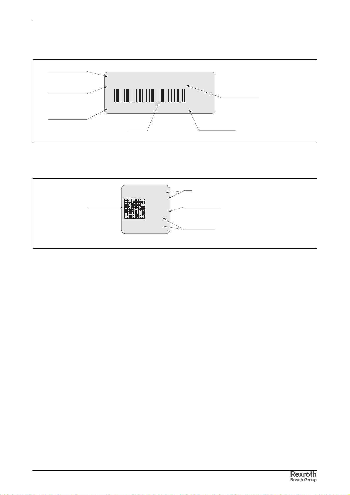
Rexroth IndraDrive Identification, Transport, Storage, Installation Conditions 4-5
Type Plates at the Control Section
Control Section Type Plate
Type
CSH01.1C-SE-EN1-EN2-MA1-L1-S-NN-FW
Part number
Serial number
MNR: R911293808 FD: 05W24 (7260)
Production week
Example: 05W24 means year 2005, week 24
SN:CSH011-00123 0A01 0S01
Barcode
Barcode
Fig. 4-10: Control section type plate
Hardware index
Firmware Type Plate
Type
MPH02V12D51
SRVNN
(7260)
05W24
Production week
Example: 05W24 means year 2005, week 24
R911
297901-04432
Fig. 4-11: Firmware type plate (example)
Serial number
DG000022v01_de.FH9
DG000024v01_en.fh9
DOK-INDRV*-FU*********-IB01-EN-P
Page 46
4-6 Identification, Transport, Storage, Installation Conditions Rexroth IndraDrive
4.2 Transport and Storage
Transport of the Devices
Conditions
temperature -25…70 °C
relative humidity 5…95%;
climatic category 2K3
absolute humidity 1…60 g/m
climatic category 2K3
moisture condensation not allowed
icing not allowed
shock test out of operation according
to EN 60068-2-27
Fig. 4-12: Conditions for transport
half sine in 3 axes: 10g / 11ms
3
Storage of the Devices
Extended Storage
Conditions
temperature -25…55 °C
relative humidity 5…95%;
climatic category 1K3
absolute humidity 1…29 g/m
climatic category 1K3
moisture condensation not allowed
icing not allowed
Fig. 4-13: Conditions for storage
Some devices contain electrolytic capacitors which may deteriorate during
storage.
Note: When storing these devices for a longer period of time,
operate them once a year for at least 1 hour with power ON:
• devices HCS with mains voltage U
3
LN
DOK-INDRV*-FU*********-IB01-EN-P
Page 47
Rexroth IndraDrive Identification, Transport, Storage, Installation Conditions 4-7
4.3 Installation Conditions
Ambient and Operating Conditions
The drive controllers and their additional components are designed for
control cabinet mounting!
Note: The user must c heck that the am bient conditions, in particular
the control cabinet temperature, are complied with by
calculating the heat levels in the control cabinet and making
the corresponding measurements.
In the Technical Data the power dissipation is indicated as an
input value for calculating the heat levels.
Designation Data
degree of protection IP20 according to IEC529
ambient temperature 0…+40 °C
ambient temperature with power
reduction
temperature during storage see section 4.2 Transport and Storage
temperature during transport see section 4.2 Transport and Storage
installation altitude with nominal data <1000 m above sea level
installation altitude with power
reduction *
maximum installation altitude * 4000 m
relative humidity
(operation)
absolute humidity 1…29 g/m
climatic category Cl. 3K3 according to IEC721
0…+55 °C; see characteristic in Fig. 4-15
see characteristic in Fig. 4-16
(upper temperature level reduced to 40 °C instead of 55 °C)
5%…95%
Cl.3K5 with restriction, as not –5 °C
3
degree of dirt contamination degree of dirt contamination 2 in accordance with EN50178
dust, steam allowed according to EN 50178, table A.2
sine vibration during operation
according to EN 60068-2-6
noise vibration (random) during
operation according to IEC 68-2-36
DOK-INDRV*-FU*********-IB01-EN-P
amplitude and frequency: 0.15 mm (peak-peak)
at 10…57 Hz
acceleration and frequency: 1 g at 57…150 Hz
tolerance: ±15 %
frequency: 20…150 Hz
spectral acceleration density amplitude: 0.005 g2/Hz
tolerance: ± 3 dB
rms value of the total acceleration: 1.0 g
* For installation altitudes of more than 2000 m, an overvoltage limiter
for transient overvoltage 1.2/50 µs must be installed in the
installation or building in order to limit the voltage to 1.0 kV between
the outer conductors and to 2.5 kV between conductor-ground.
Fig. 4-14: Ambient and operating conditions
Page 48
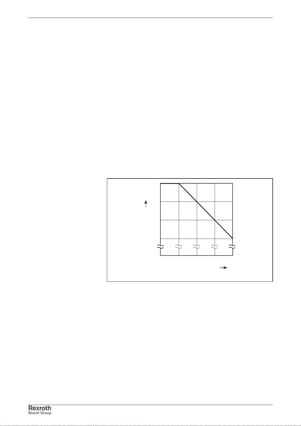
4-8 Identification, Transport, Storage, Installation Conditions Rexroth IndraDrive
Capacity Utilization
Where installation conditions differ, the following performance data are
reduced in accordance with the diagrams (see "Fig. 4-15: " and "Fig. 4-16:
"):
drive controller:
• allowed continuous DC bus power
• continuous power of braking resistor
• continuous current
motor:
• power
• continuous torque at standstill
• S1 continuous torques
• short-time service torque MKB
If differing ambient temperatures and higher installation altitudes occur
simultaneously, both capacity utilization factors must be multiplied. The
installation altitude must only be taken into account once, deviating
ambient temperatures must be taken into account separately for motor
and drive controller.
1
Load factor
0,7
5
Fig. 4-15: Capacity utilization at higher ambient temperature
40 45 50 55
Ambient temperature in °C
DK000073v01_en
DOK-INDRV*-FU*********-IB01-EN-P
Page 49
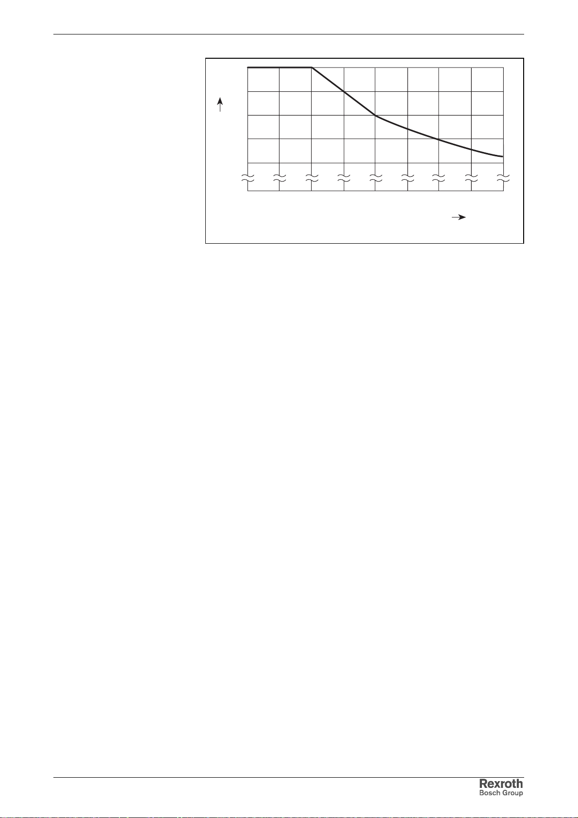
Rexroth IndraDrive Identification, Transport, Storage, Installation Conditions 4-9
1
0,9
0,8
0,7
Load factor
0,6
0
Fig. 4-16: Capacity utilization at higher installation altitude
Compatibility with Foreign Matters
All Rexroth controls and drives are developed and tes ted accor ding to the
state-of-the-art technology.
As it is impossible to follow the continuing development of all materials
(e.g. lubricants in machine tools ) which m ay interact with our controls and
drives, it cannot be completely ruled out that any reactions with the
materials used by Bosch Rexroth might occur.
For this reason, before using the res pective material a compatibility test
has to be carried out for new lubricants, cleaning agents etc. and our
housings/our housing materials.
1000 2000
Installation altitude above sea level in meters
3000 4000
DK000074v01_en
DOK-INDRV*-FU*********-IB01-EN-P
Page 50

4-10 Identification, Transport, Storage, Installation Conditions Rexroth IndraDrive
DOK-INDRV*-FU*********-IB01-EN-P
Page 51
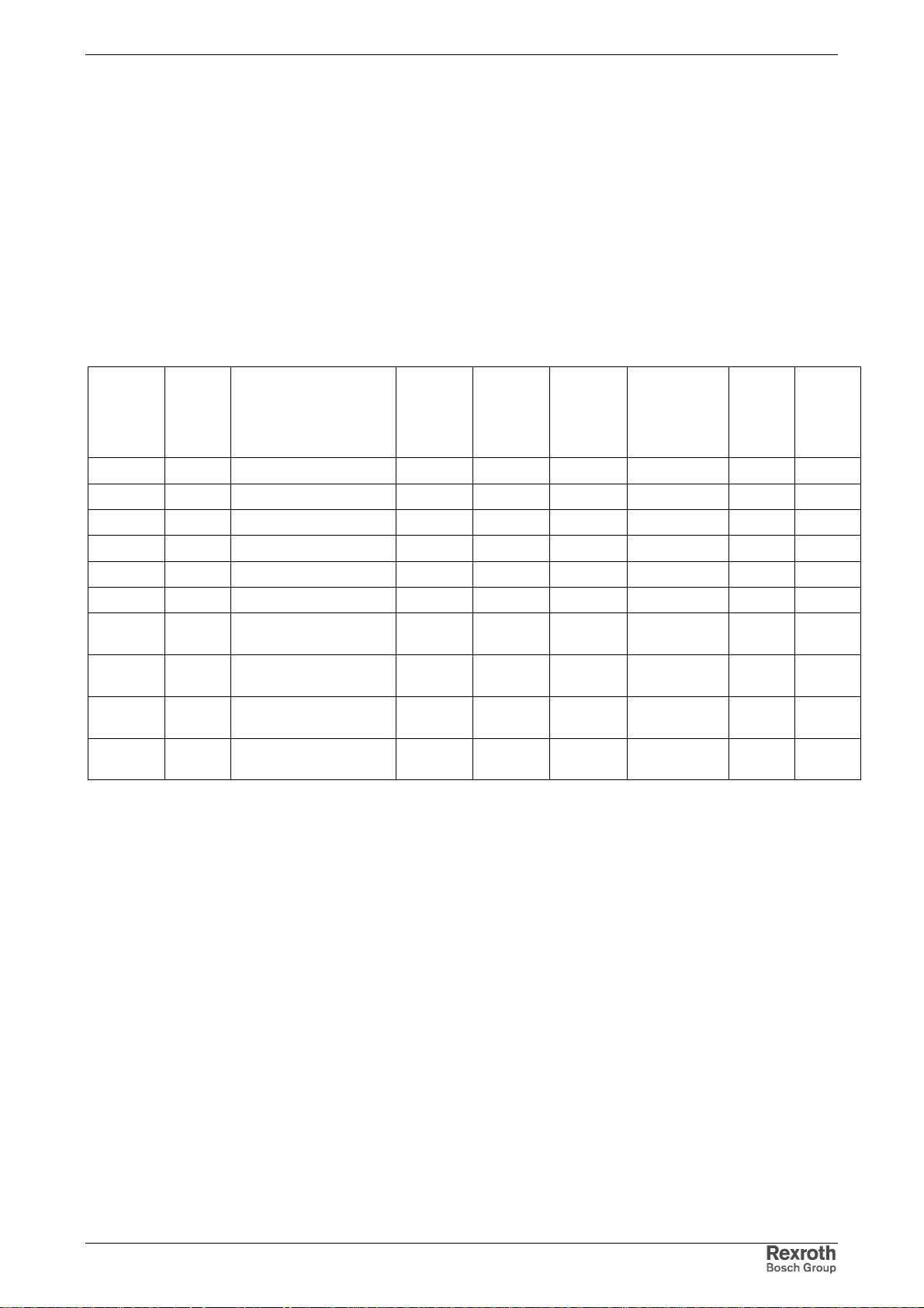
Rexroth IndraDrive Electrical Data 5-1
5 Electrical Data
5.1 Power Sections
Unless otherwise specified, the following data apply to
• T
= T
a
amax
• ULN = 3AC400V
• use of HNL and HNK mains chokes
Type Current and Connected Load
Compact
converter
HCS02 W0012 HNL01.1E-1000-N0012 1,5 3,5 6 10 4 12
HCS02 W0028 HNL01.1E-1000-N0012 4,0 7,3 13 20 11 28
HCS02 W0054 HNL01.1E-1000-N0020 7,5 13,3 19 25 22 54
HCS02 W0070 HNL01.1E-0600-N0032 11 18,5 30 35 28 70
HCS03 W0070 HNL01.1E-0571-N0050
HCS03 W0100 HNL01.1E-0362-N0080;
HCS03 W0150 HNL01.1E-0240-N0106
HCS03 W0210 HNL01.1E-0170-N0146
Type
current
Attached mains choke
HNL, HNK
HNK01.1A-A075-E0080
HNK01.1A-A075-E0080
HNK01.1A-A075-E0106
HNK01.1A-A075-E0146
(1) at fs = 4 kHz; without overload
(2) for standard motor, when using mains choke HNL01; at 3 AC 400 V
Fig. 5-1: Type current and connected load
Nominal
motor
power
(2)
[kW] [kVA] [A] [A] [A] [A]
18,5 35 50 3NA6820-4 45 70
30 55,2 80 3NA6824-4 73 100
45 72,9 106 3NA6832-4 95 150
75 99,3 146 3NA6836-4 145 210
variable torque, low overload
Connected load
S
LN
Mains
input
contin.
current
I
L_cont
Nominal fuse
current / fuse
type
character-
istic gL
Type I
Contin.
current
(1)
out_cont1Iout_max
Peak
current
(1)
DOK-INDRV*-FU*********-IB01-EN-P
Page 52
5-2 Electrical Data Rexroth IndraDrive
Control Voltage Supply
Note: The control sections are supplied via the term inal connectors
24V and 0V at the power section (24V supply).
Note: The isolated inputs/outputs at X31 and X32 are not supplied
via the connections of the 24V supply of the power section. A
separate voltage supply is required for these inputs/outputs.
Note: Overvoltage of more than 33 V has to be discharged by
means of the appropriate elec trical equipment of the m achine
or installation.
This equipment includes:
• 24V power supply units that reduce incoming overvoltages
to the allowed value.
• Overvoltage limiters at the control cabinet input that limit
existing overvoltage to the allowed value. This, too, applies
to long 24V lines that have been run in parallel to power
cables and mains cables and c an absorb overvoltages by
inductive or capacitive coupling.
Designation Symbol Unit
24V control voltage supply
HCS02.1E;
HCS03.1E
U
N3
V
• 24 ± 20%
(if no motor holding brake has to be supplied)
• If motor holding brakes are to be supplied, observe
the data of the motor documentation. The following
values are normally sufficient:
24 ± 5% at motor cable length < 50 m
26 ± 5% at motor cable length > 50 m
max. ripple content w - mustn't exceed the control voltage range
max. allowed overvoltage U
N3max
V 33 (max. 1 ms)
Power consumption of power sections 1)
HCS02.1E-W0012 P
HCS02.1E-W0028 P
HCS02.1E-W0054 P
HCS02.1E-W0070 P
HCS03.1E-W0070 P
HCS03.1E-W0100 P
HCS03.1E-W0150 P
HCS03.1E-W0210 P
N3
N3
N3
N3
N3
N3
N3
N3
W12
W14
W23
W23
W23
W25
W25
W30
Power consumption of control sections 2)
CSB01.1N-FC… P
CSB01.1N-PB… P
N3
N3
W7,5
W7,5
Typ. inrush current of control sections
DOK-INDRV*-FU*********-IB01-EN-P
Page 53
Rexroth IndraDrive Electrical Data 5-3
CSB01.1N-FC… I
CSB01.1N-PB… I
EIN3
EIN3
A 1,5 (pulse width t
A 5 (pulse width t
EIN3lade
EIN3lade
ca. 120 ms)
ca. 40 ms)
Power consumption of optional modules according to type code 3), 4)
CP
EN1 P
EN2 P
ENS P
MA1 P
MD1 P
SP
N3
N3
N3
N3
N3
N3
N3
W1,0
W6,0
W5,5
W5,5
W2,0
W1,0
W1,0
1) plus control section with optional modules
2) plus optional modules
3) code from the control section type code
4) at max. allowed output load without circuits to be supplied externally
Fig. 5-2: Control voltage
Power Voltage Supply- Mains Connection
Designation Symbol Unit HCS02.1E HCS03.1E
allowed range of mains input
voltage, three-phase;
TN-S, TN-C, TT mains
allowed range of mains input
voltage, three-phase;
IT mains
allowed range of mains input
voltage, single-phase
U
LN
U
LN
U
LN
V
V
V 1 * AC (200…250) +-10% not allowed
3 * AC (200…500)
+-10%
3 * AC (200…230)
+-10%
3 * AC (400…500)
+10% -15%
not allowed
rotary field no rotary field condition
allowed range of mains
frequency
max. allowed mains frequency
change
f
LN
d f
/t Hz/s 2% * f
LN
Hz (50…60) + - 2
LN
Fig. 5-3: Extended range of power voltage
Note: When using HCS02 and HCS03 devic es in the mains voltage
range up to 3 * AC 500 V, make sure the additional
components you use may be operated in this mains voltage
range. NFD mains filters , for exam ple, can only be used up to
3 * AC 480 V.
DOK-INDRV*-FU*********-IB01-EN-P
Page 54
5-4 Electrical Data Rexroth IndraDrive
Limited Length of Motor Power Cables
Keep in mind, that the allowed maxim um m otor cable length is depending
on the switching frequency of the power output stage. On principle, the
higher the switching frequency, the shorter the allowed cable length (in
order to protect the drive controllers against overload).
Note: Always use switching frequencies supported by the
components of your drive system. Observe the technical data
of the drive controllers and motors.
See also Parameter Description "P-0-0001, Switching frequency of the
power output stage".
Limited Lengths of Motor Power
Cables
The lengths indicated in the table below are recommended as guide
values (at an ambient temperature of ≤ 40 °C in accordance with
EN 60 204).
Allowed line lengths for motor connection without filter measures at
motor output:
Max. allowed line length [m]PWM frequency [kHz]
Shielded line Unshielded line
2)
2
4 75 150
8 38 150
12 25 not allowed
16 18 not allowed
1) only allowed at HCS drive controllers
2) depending on the drive controller
Fig. 5-4: Line lengths
100 175
1)
Operation with unshielded motor cables of up to 150 m
• aims at applications with "operation without encoder" (Open Loop)
• does not include the control voltage lines to the motor
• requires additional measures with regard to EMC on the part of the
operating company
Documentation Motor Power
Cables
Allowed line lengths for motor connection with additional components
HMF or HML:
Max. allowed line length [m]PWM frequency [kHz]
Shielded line Unshielded line
2)
4
1) only allowed at HCS03 drive controllers
2) higher PW M frequencies are not allowed
Fig. 5-5: Line lengths
75 200
1)
The documentation "Rexroth Connection Cables; Selection Data" is
available for selecting the motor power cables and other connections,
such as encoder cables.
Rexroth IndraDrive drive systems have to be equipped with shielded
motor power cables of the RKL line.
DOK-INDRV*-FU*********-IB01-EN-P
Page 55

Rexroth IndraDrive Electrical Data 5-5
Third-Party Motor Power Cables
Requirements on third-party motor power cables:
Maximum allowed cable length at A1, A2, A3:
• see description above
Maximum allowed capacitance per unit length at A1, A2, A3:
• against ground, each: 0.5 nF/m
• against each other: 0.5 nF/m
Maximum allowed inductance per unit length at A1, A2, A3:
• 100 nH/m each
Note: If you use third-party motor power cables not corresponding to
the requirements, Rexroth's guarantee for the drive s ystem will
expire.
Use ready-made Rexroth cables.
DOK-INDRV*-FU*********-IB01-EN-P
Page 56
5-6 Electrical Data Rexroth IndraDrive
5.2 Control Sections
Relay Contact Type 1
Data Unit Min. Typ. Max.
current load capacity A DC 1
AC 2
voltage load capacity V DC 30
AC 250
minimum contact load mA 10
contact resistance at
minimum current
switching actions at max. time
constant of load
number of mechanical
switching cycles
time constant of load ms 50
pick up delay ms 10
drop out delay ms 10
mOhm 1000
100.000
6
1 * 10
Relay Contact Type 2
Fig. 5-6: Relay contacts type 1
Data Unit Min. Typ. Max.
current load capacity A DC 1
voltage load capacity V DC 30
minimum contact load mA 10
contact resistance at
minimum current
switching actions at max. time
constant of load
number of mechanical
switching cycles
time constant of load ms ohmic
pick up delay ms 10
drop out delay ms 10
Fig. 5-7: Relay contacts type 2
mOhm 1000
6
1 * 10
8
1 * 10
DOK-INDRV*-FU*********-IB01-EN-P
Page 57
Rexroth IndraDrive Electrical Data 5-7
Relay Contact Type 3
Data Unit Min. Typ. Max.
current load capacity A DC 1
voltage load capacity V DC 30
minimum contact load mA 10
contact resistance at
minimum current
switching actions at max. time
constant of load
number of mechanical
switching cycles
time constant of load ms ohmic
pick up delay ms 10
drop out delay ms 10
Fig. 5-8: Relay contacts type 3
mOhm 1000
6
1 * 10
7
1 * 10
Digital Inputs/Outputs
Digital Inputs
The digital inputs correspond to IEC 61131, type 1.
1
DA000022v01_nn.FH9
Fig. 5-9: Symbol of digital input
Data Unit Min. Typ. Max.
allowed input voltage V -3 30
On V 15
Off V 5
input current mA 2 5
input resistance kOhm non-linear, varies depending on
input voltage
sampling frequency kHz depending on firmware
probe input delay us 1
DOK-INDRV*-FU*********-IB01-EN-P
Fig. 5-10: Digital inputs
Note: Probe inputs are fast inputs. For triggering use bounce-free
switches.
Page 58
5-8 Electrical Data Rexroth IndraDrive
Digital Outputs
The digital outputs correspond to IEC 61131.
Note: Do not operate digital outputs at low-resistance sources.
Observe Functional Description of the f irm ware s ection "Notes
on Commisioning" particularly parameter P-0-0302, Digital I/O,
Direction.
1
DA000024v01_nn.FH9
Fig. 5-11: Symbol of digital output
Data Unit Min. Typ. Max.
output voltage "ON" V Uext - 0,5 24 Uext
output voltage "OFF" V 2,1
output current "OFF" mA 0,05
allowed output current per
output
allowed output current total
or per group
update interval ns depending on firmware
short circuit protection present
overload protection present
allowed energy content of
connected inductive loads,
e.g. relay coils; only allowed
as single pulse
Fig. 5-12: Digital outputs
mA 500
mA 1000
mJ 400
Note: The digital outputs have been realized with so-called high-side
switches. This means that these outputs can actively supply
current but not drain it.
Note: The energy absorption capacity of the outputs is us ed to limit
voltage peaks caused when inductive loads are switched off.
Limit voltage peaks by using free-wheeling diodes directly at
the relay coil.
DOK-INDRV*-FU*********-IB01-EN-P
Page 59
Rexroth IndraDrive Electrical Data 5-9
Analog Inputs/Outputs
The analog inputs correspond to IEC 61 131.
Analog Input Type 1
R
U+
U-
GND
AD: analog/digital converter
Fig. 5-13: Analog voltage inputs
Data Unit Min. Typ. Max.
allowed input voltage
voltage inputs
input resistance
voltage input
input bandwidth kHz 6
common-mode range V -20 +20
common-mode rejection dB
relative measuring error
at 90% U
emax
converter width A/D converter
incl. polarity sign
oversampling 8-fold
dynamic converter width with
oversampling
resulting resolution mV/Ink 5,5
cyclic conversion us 500 (depending on firmware)
conversion time us n.s.
u
AD
R
u
DA000025v01_nn.FH9
V-10 +10
kOhm 180
%-1 +1
Bit 10
Bit 12
DOK-INDRV*-FU*********-IB01-EN-P
Fig. 5-14: Analog voltage inputs
Page 60
5-10 Electrical Data Rexroth IndraDrive
Analog Input Type 2
R
U+
U-
GND
AD: analog/digital converter
Fig. 5-15: Analog voltage inputs
Data Unit Min. Typ. Max.
allowed input voltage
voltage inputs
input resistance
voltage input
input bandwidth kHz 50
common-mode range V -50 +50
common-mode rejection dB 70
relative measuring error
at 90% U
emax
converter width A/D converter
incl. polarity sign
oversampling 8-fold
dynamic converter width with
oversampling
resulting resolution mV/Ink 1,25
cyclic conversion us 500 (depending on firmware)
conversion time us 40
u
AD
R
u
DA000025v01_nn.FH9
V-10 +10
kOhm 1000
% -0,3 +0,3
Bit 12
Bit 14
Fig. 5-16: Analog voltage inputs
DOK-INDRV*-FU*********-IB01-EN-P
Page 61
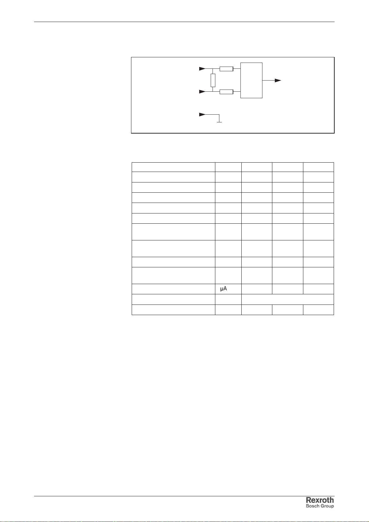
Rexroth IndraDrive Electrical Data 5-11
Analog Input Type 3
R
I+
i
AD
DA000026v01_nn.FH9
GND
R
s
R
I-
i
AD: analog/digital converter
Fig. 5-17: Analog current inputs
Data Unit Min. Typ. Max.
allowed input current mA 0 +20
input resistance Ohm 200
input bandwidth kHz 3
common-mode range V -20 +20
common-mode rejection dB
relative measuring error
at 90% U
emax
converter width A/D converter
%-1 +1
Bit 10
incl. polarity sign
oversampling 8-fold
dynamic converter width with
Bit 12
oversampling
resulting resolution
µ
A/Ink 5,45
cyclic conversion us 500 (depending on firmware)
conversion time us n.s.
Fig. 5-18: Analog current inputs
DOK-INDRV*-FU*********-IB01-EN-P
Page 62
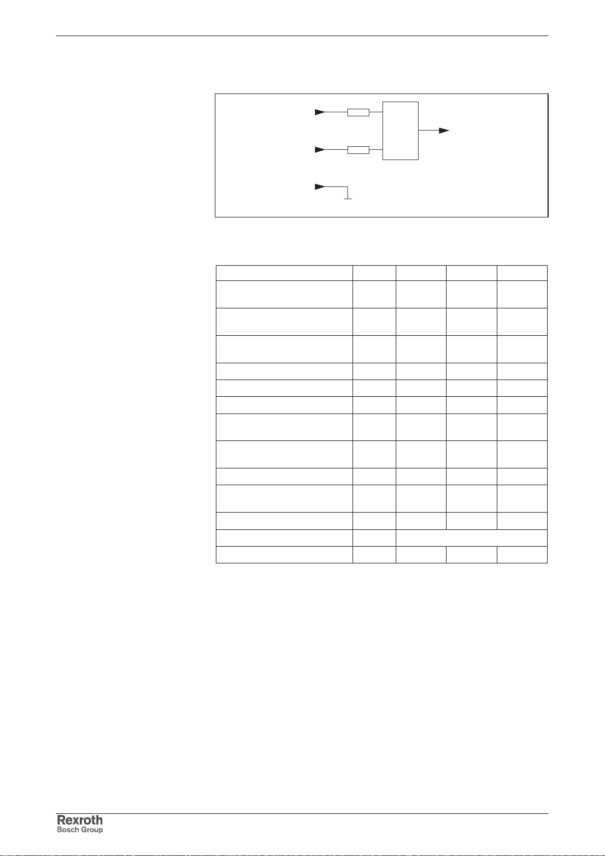
5-12 Electrical Data Rexroth IndraDrive
Analog Input Type 4
R
U+
U-
GND
AD: analog/digital converter
Fig. 5-19: Analog voltage inputs
Data Unit Min. Typ. Max.
allowed input voltage
voltage inputs
input resistance
voltage input
input resistance
voltage input CSH01.2C
input bandwidth kHz 10
common-mode range V -20 +20
common-mode rejection dB
relative measuring error
at 90% U
emax
converter width A/D converter
incl. polarity sign
oversampling 8-fold
dynamic converter width with
oversampling
resulting resolution mV/Ink 1,23
cyclic conversion us 500 (depending on firmware)
conversion time us n.s.
u
AD
R
u
DA000025v01_nn.FH9
V-10 +10
kOhm 2
kOhm 160
%-1 +1
Bit 12
Bit 14
Fig. 5-20: Analog voltage inputs
DOK-INDRV*-FU*********-IB01-EN-P
Page 63
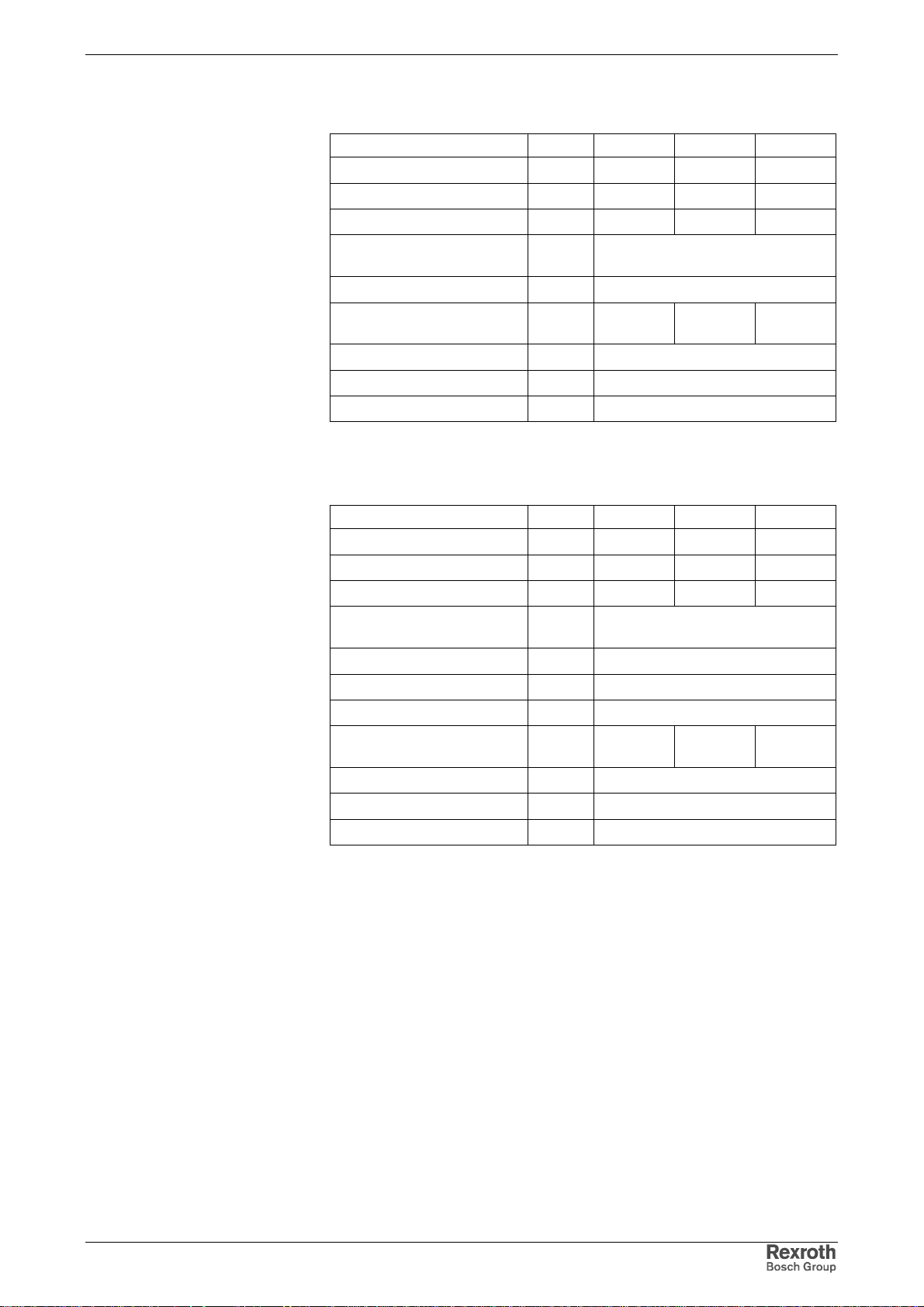
Rexroth IndraDrive Electrical Data 5-13
Analog Output Type 1
Data Unit Min. Typ. Max.
output voltage V 0 +10
output load kOhm 2
output current mA 0 +5
converter width digital/analog
converter incl. polarity sign
resolution mV/Ink 9,8
conversion time
(incl. response time)
cyclic conversion us depending on firmware
short circuit protection present
overload protection present
Fig. 5-21: Analog outputs type 1
Bit 10
us 10
Analog Output Type 2
Data Unit Min. Typ. Max.
output voltage V 0 +5
output load kOhm 5
output current mA 0 +1
converter width digital/analog
converter incl. polarity sign
resolution mV/Ink 19,5
accuracy at R=5 kOhm % 5 of FMR
accuracy at R=10 kOhm % 2,5 of FMR
conversion time
(incl. response time)
cyclic conversion us depending on firmware
short circuit protection present
overload protection present
FMR: final value of measuring range
Fig. 5-22: Analog outputs type 2
Bit 8
us 10
DOK-INDRV*-FU*********-IB01-EN-P
Page 64
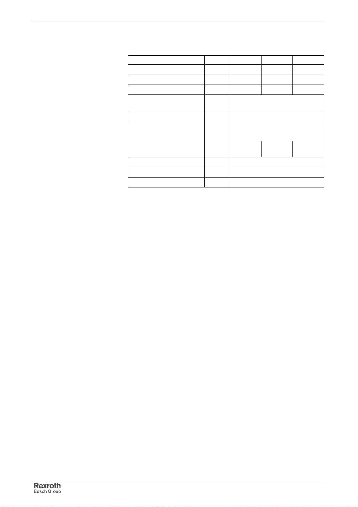
5-14 Electrical Data Rexroth IndraDrive
Analog Output Type 3
Data Unit Min. Typ. Max.
output voltage V -10 +10
output load kOhm 1
output current mA 0 +1
converter width digital/analog
converter incl. polarity sign
resolution mV/Ink 5
accuracy at R = 1 kOhm % 1 of FMR
accuracy at R = 10 kOhm % 0,2 of FMR
conversion time
(incl. response time)
cyclic conversion us depending on firmware
short circuit protection present
overload protection present
FMR: final value of measuring range
Fig. 5-23: Analog outputs type 3
Bit 12
us 10
DOK-INDRV*-FU*********-IB01-EN-P
Page 65
Rexroth IndraDrive Electrical Data 5-15
1)
5.3 Additional Components
Mains Filter HNF
HNF01.1A- … -A-480-NNNN
Unit
Power dissipation W < 89 < 91 < 127 < 174 < 238 < 373 < 73 < 77 < 163 < 157 < 135 < 146
Phase current (continuous
current)
Phase current (peak
current
Leakage current at filters
input (line side)
Leakage current at filters
output (load side)
allowed THD (Total Harmonic
Distortion)
Reduction of allowed
operating data due to
harmonic content
Input supply voltage V 3 x AC 380…480V ±10%, 50/60Hz ±2%
Sum of leakage currents at
filters input with power supply
unit switched off:
• 1 phase failed
• 2 phases failed
Leakage resistance (Phase –
Ground)
Protection category - I P20
Materials - free of asbestos and silicone
Terminal L1, L2, L3 resp. L1.1, L2.1, L3.1:
Cross section flexible min. mm
Cross section flexible max. mm
Cross section rigid min. mm
Cross section rigid max. mm
Cross section AWG min. -- 20 20 6 6 2 2 20 20 10 10 6 6
Cross section AWG max. -- 4 4 0 0 00/3 00/3 6 6 2 2 0 0
Tightening torque Nm
A 51 51 125 125 202 202 26 26 65 65 94 94
A 77 77 188 188 303 303 65 65 163 163 235 235
)
A < 2 < 2 < 2,2 < 2,2 < 2,5 < 2,5 < 2 < 2 < 2 < 2 < 2,2 < 2,2
A < 2 < 2 < 2,2 < 2,2 < 2,5 < 2,5 < 2 < 2 < 2 < 2 < 2,2 < 2,2
% see Project Pl anni ng Manual " Rexroth IndraDri ve Dri ve S ystem"
- s ee Project Planning Manual "Rexroth IndraDrive Drive System"
A
MOhm > 15
F240-E0051
M900-E0051
F240-E0125
M900-E0125
F240-E0202
M900-E0202
F240-R0026
M900-R0026
F240-R0065
M900-R0065
• < 0,83
• < 1,4
2
0,5 0,5 16 16 50 50 0,5 0,5 10 10 16 16
2
16 16 50 50 150 150 10 10 25 25 50 50
2
0,5 0,5 16 16 35 35 0,5 0,5 6 6 16 16
2
25 25 50 50 150 150 16 16 35 35 50 50
4,8
±0,5
4,8
< 25 < 25 < 25 < 25
±0,5
4,8
±0,5
4,8
±0,5
4,8
±0,5
4,8
±0,5
1) duration: 300 ms ;
cycle duration:
for feeding units: 0,67 s;
for regenerating units: 1,42 s;
base load: 60% (continuous current)
Fig. 5-24: Data HNF
F240-R0094
< 25 < 25
M900-R0094
DOK-INDRV*-FU*********-IB01-EN-P
Page 66
5-16 Electrical Data Rexroth IndraDrive
Mains Filter (-Combi nati on) HNK
Mains filter HNK01.1A-A075 Unit E0050 E0080 E0106 E0146
Nominal voltage V 3*AC400…500
Nominal current A 50 80 106 146
Inductance µH 571 362 240 170
Connection cross section mm² 16 (AWG 6) 25 (AWG 3) 25 (AWG 3) 50 (AWG 1/0)
Protection category - IP20
Weight kg 15 20 20 28
Fig. 5-25: Data HNK
Mains Choke HNL01.1E (feeding)
Mains choke U
HNL01.1E-1000-N0012-A-500-NNNN 500 12 3 x 1000 40 25 50% of L
HNL01.1E-1000-N0020-A-500-NNNN 500 20 3 x 1000 60 50 50% of L
HNL01.1E-0600-N0032-A-500-NNNN 500 32 3 x 600 75 80 50% of L
HNL01.1E-0571-N0050-A-500-NNNN 500 50 3 x 571 50 100 50% of L
HNL01.1E-0400-N0051-A-480-NNNN 480 51 3 x 400 165 77 50% of LN16 (a, b: 2,5)
HNL01.1E-0362-N0080-A-500-NNNN 500 80 3 x 362 80 160 50% of L
HNL01.1E-0240-N0106-A-500-NNNN 500 106 3 x 240 100 212 50% of L
HNL01.1E-0200-N0125-A-480-NNNN 480 125 3 x 200 170 188 50% of LN70 (a, b: 2,5)
HNL01.1E-0170-N0146-A-500-NNNN 500 146 3 x 170 130 292 50% of L
HNL01.1E-0100-N0202-A-480-NNNN 480 202 3 x 100 200 303 50% of LN150 (a, b: 2,5)
N
[V]
I
[A]
N
L
N
[µH]
P
[W]
V
I
max
[A]
at I
L
min
max
N
N
N
N
N
N
N
Connection
cross section
[mm²]
4 (a, b: 4)
6 (a, b: 4)
10 (a, b: 4)
16 (a, b: -)
35 (a, b: -)
50 (a, b: -)
95 (a, b: -)
Fig. 5-26: Data HNL
Temperature Contact a, b
Switching Capacity
Switching Temperature
1 A / AC 250 V; DC 24 V
125 °C
Note: HNL01.1E mains chokes of type 1 are equipped with a
temperature contact (a, b), types 2, 3 and 4 are not.
DOK-INDRV*-FU*********-IB01-EN-P
Page 67
Rexroth IndraDrive Electrical Data 5-17
Mains Choke HNL01.1E-****-S (Current-Compensated)
HNL01.1 … -A-480-NNNN
Weight kg 11 26 30 12 14 24
Inductance LNmH 3 x 5,7 3 x 2,8 3 x 3,4 3 x 4,2 3 x 6,3 3 x 3,0
Nominal current A 51 125 202 26 65 94
Peak current
Total leakage current at power terminal A < 2 < 2,2 < 2,2 < 2 < 2 < 2
Allowed power dissipation at nominal current and
maximum leakage current
Input supply voltage 3 x AC 380…480V ±10%, 50/60Hz ±2%
Minimum inductance L
Protection category IP20
1) duration: 300 ms ;
Fig. 5-27: Data HNL…S
Braking Resistor HLR
HLR01.1N-xxxx-Nxxxx-A-007-NNNN
Unit
1)
A 77 188 303 65 163 235
E-5700-S0051
E-2800-S0125
E-3400-S0202
R-4200-S0026
W 83 179 320 80 138 142
min
0,8*LN at I
max
cycle duration:
for feeding units: 0,67 s;
for regenerating units: 1,42 s;
base load: 60%
R-6300-S0065
R-3000-S0094
Designation Symbol Unit 0300-N17R5 0470-N11R7 0780-N07R0 1K08-N05R0
nominal braking resistance
braking resistor continuous
power, at Ta < 40 °C
resistance value at P
BD
braking resistor peak power
at U
= 850 V
DC
max. regenerative power that
can be absorbed
max. allowed duty cycle
min. allowed cycle time
time constant
weight
R
DC_Bleeder
P
BD
P
BS
W
R_max
ts 1 1 1 1
t s 120 120 120 120
mkg 3 4,5 5,5 8
Ohm 17,5 11,7 7,0 5,0
kW 0,30 0,47 0,78 1,08
Ω
kW 35 52 88 124
kWs 37 56 93 130
s 780 780 780 780
20,5 13,7 8,2 5,8
connection cross section
mm² 10 25 25 50
AWG 8 3 3 1/0
Fig. 5-28: Data
DOK-INDRV*-FU*********-IB01-EN-P
Page 68
5-18 Electrical Data Rexroth IndraDrive
Braking Resistors for HCS03.1E-W0070
HLR01.1N-xxxx-xxxxx-A-007-
-01K6-N18R0 -03K5-N19R0 -04K5-N18R0 -06K5-N18R0 -10K0-N18R0
NNNN
continuous power kW 1,6 3,5 4,5 6,5 10
resistance value in
operating status
type A5 B1 B2 B2 B3
Energy absorption at peak power, duty cycle t = x sec and load cycle T = 120 sec
energy absorption at peak
power
peak power kW 34 31 33 33 33
t sec 3,3 8 13 21 32
duty cycle ED % 2,7 6,7 11 17 27
Braking power at x % ED and a load cycle T = 120 sec
braking power kW 15 14 14 14 15
t sec7,218304872
ED % 6 15 25 40 60
Connection cross sec t i o n
Ω
kWs 109 252 432 686 1080
mm² 2,5 4 6 10 10
AWG 14 12 10 8 8
20,0 21,3 20,2 20,2 20,2
Fig. 5-29: Technical data for braking resistors at HCS03.1E-W0070
DOK-INDRV*-FU*********-IB01-EN-P
Page 69
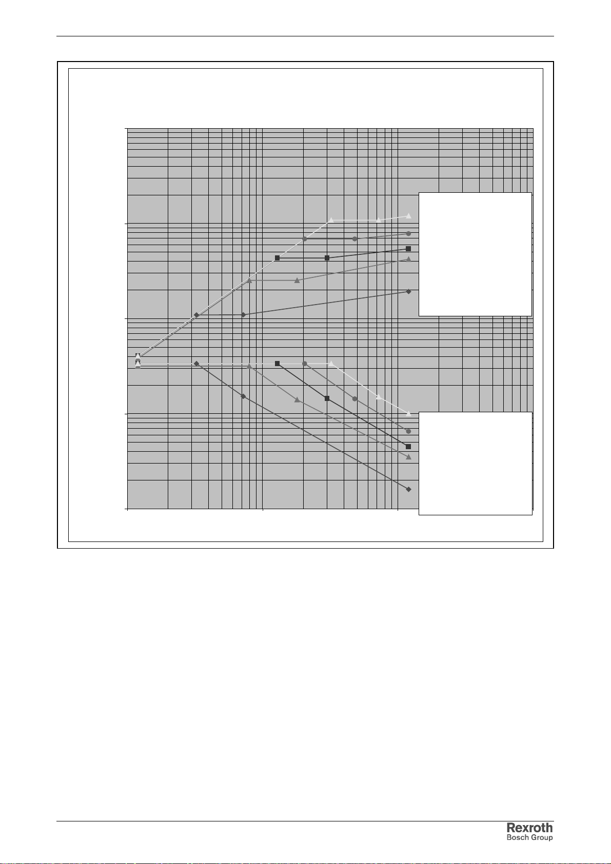
Rexroth IndraDrive Electrical Data 5-19
Braking resistors for HCS03 ... 0070
Peak power P_s and Energy absorption W
10000
W [kWs]
Energy
HLR01.1N-10K0-N18R0
1000
HLR01.1N-06K5-N18R0
HLR01.1N-04K5-N18R0
HLR01.1N-03K5-N19R0
P_s [kW]
HLR01.1N-01K6-N18R0
100
10
1
1 10 100 1000
Power
HLR01.1N-10K0-N18R0
HLR01.1N-06K5-N18R0
HLR01.1N-04K5-N18R0
HLR01.1N-03K5-N19R0
HLR01.1N-01K6-N18R0
Duty cycle [s]
Fig. 5-30: Selection aid for braking resistors for HCS03.1E-W0070
DOK-INDRV*-FU*********-IB01-EN-P
Page 70
5-20 Electrical Data Rexroth IndraDrive
Braking Resistors for HCS03.1E-W0100
HLR01.1N-xxxx-xxxxx-A-007NNNN
continuous power kW 2 5 7 9,5 14,5
resistance value in
operating status
type A6 B2 B3 B3 B4
Energy absorption at peak power, duty cycle t = x sec and load cycle T = 120 sec
energy absorption at
peak power
peak power kW 40 40 43 46 46
t sec 3,4 9 16 22 34
duty cycle ED % 2,8 7,5 13 18 28
Braking power at x % ED and a load cycle T = 120 sec
braking power kW 19 20 22 21 22
t sec7,218304872
ED % 6 15 25 40 60
connection cross section
kWs 137 360 672 1003 1566
mm² 4 6 10 10 16
AWG1210886
-02K0-N15R0 -05K0-N15R0 -07K0-N14R0 -09K5-N13R0 -14K5-N13R0
Ω
16,7 16,9 15,7 14,6 14,6
Fig. 5-31: Technical data for braking resistors at HCS03.1E-W0100
DOK-INDRV*-FU*********-IB01-EN-P
Page 71
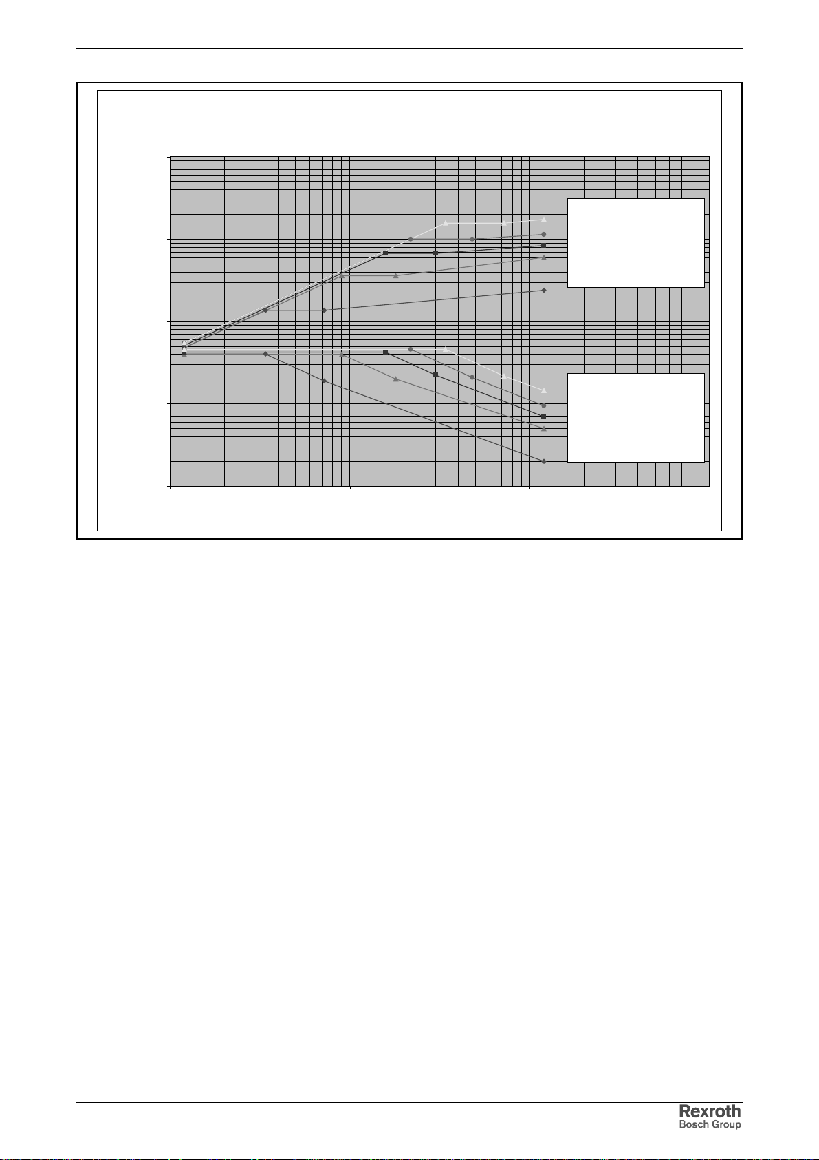
Rexroth IndraDrive Electrical Data 5-21
Braking resistors for HCS03 ... 0100
Peak power P_s and Energy absorption W
10000
W [kWs]
Energy
HLR01.1N-14K5-N13R0
1000
P_s [kW]
100
10
HLR01.1N-09K5-N13R0
HLR01.1N-07K0-N14R0
HLR01.1N-05K0-N15R0
Power
HLR01.1N-14K5-N13R0
HLR01.1N-09K5-N13R0
HLR01.1N-07K0-N14R0
HLR01.1N-05K0-N15R0
1
1 10 100 1000
Duty cycle [s]
Fig. 5-32: Selection aid for braking resistors for HCS03.1E-W0100
DOK-INDRV*-FU*********-IB01-EN-P
Page 72
5-22 Electrical Data Rexroth IndraDrive
Braking Resistors for HCS03.1E-W0150
HLR01.1N-xxxx-xxxxx-A-007NNNN
continuous power kW 4,5 8,5 11 15 24
resistance value in
operating status
type B1 B3 B3 B4 C3
Energy absorption at peak power, duty cycle t = x sec and load cycle T = 120 sec
energy absorption at
peak power
peak power kW 81 75 82 74 83
t sec 3 8,2 13 21 31
duty cycle ED % 2,5 6,8 11 18 26
Braking power at x % ED and a load cycle T = 120 sec
braking power kW 34 34 35 33 36
t sec7,218304872
ED % 6 15 25 40 60
connection cross section
kWs 246 612 1056 1584 2592
mm² 10 16 25 25 35
AWG86332
-04K5-N07R4 -08K5-N08R0 -11K0-N07R3 -15K0-N08R1 -24K0-N07R2
Ω
8,3 9,0 8,2 9,1 8,1
Fig. 5-33 Technical data for braking resistors at HCS03.1E-W0150
DOK-INDRV*-FU*********-IB01-EN-P
Page 73
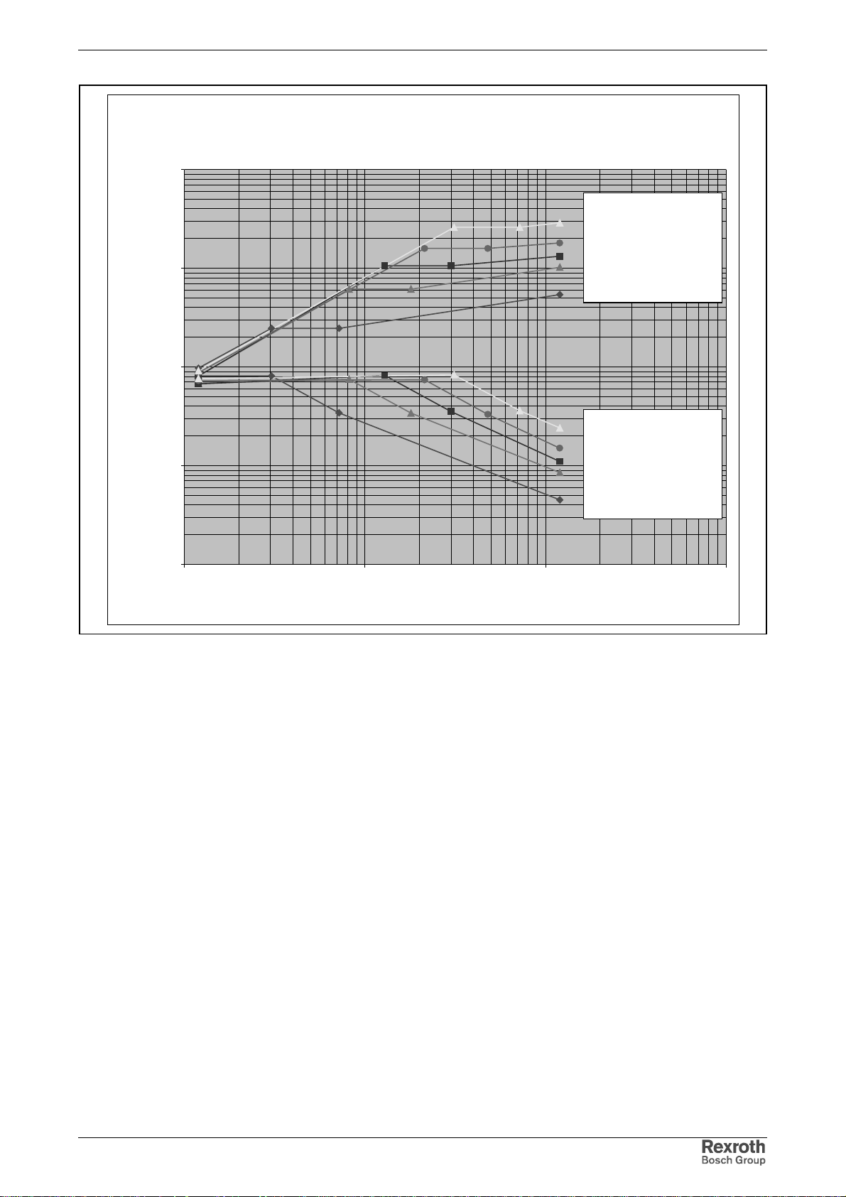
Rexroth IndraDrive Electrical Data 5-23
Braking resistors for HCS03 ... 0150
Peak power P_s an d Energy absorpt ion W
10000
W [kWs]
1000
P_s [kW]
Energy
HLR01.1N-24K0-N07R2
HLR01.1N-15K0-N08R1
HLR01.1N-11K0-N07R3
HLR01.1N-08K5-N08R0
HLR01.1N-04K5-N07R4
100
Power
HLR01.1N-24K0-N07R2
HLR01.1N-15K0-N08R1
HLR01.1N-11K0-N07R3
10
1
1 10 100 1000
HLR01.1N-08K5-N08R0
HLR01.1N-04K5-N07R4
Duty cycle [s]
Fig. 5-34: Selection aid for braking resistors for HCS03.1-W0150
DOK-INDRV*-FU*********-IB01-EN-P
Page 74
5-24 Electrical Data Rexroth IndraDrive
Braking Resistors for HCS03.1E-W0210
HLR01.1N-xxxx-xxxxx-A-007NNNN
continuous power kW 6,5 12,5 17 23 36
resistance value in
operating status
type B2 B4 B5 C2 C4
Energy absorption at peak power, duty cycle t = x sec and load cycle T = 120 sec
energy absorption at
peak power
peak power kW 98 109 117 109 111
t sec 3,6 8,3 14 22 35
duty cycle ED % 3 6,9 12 18 29
Braking power at x % ED and a load cycle T = 120 sec
braking power kW 49 50 54 51 54
t sec7,218304872
ED % 6 15 25 40 60
connection cross section
kWs 356 900 1632 2429 3888
mm² 16 35 35 50 50
AWG 6 2 2 1/0 1/0
-06K5-N06R1 -12K5-N05R5 -17K0-N05R1 -23K0-N05R5 -36K0-N05R4
Ω
76666
Fig. 5-35: Technical data for braking resistors at HCS03.1E-W0210
DOK-INDRV*-FU*********-IB01-EN-P
Page 75
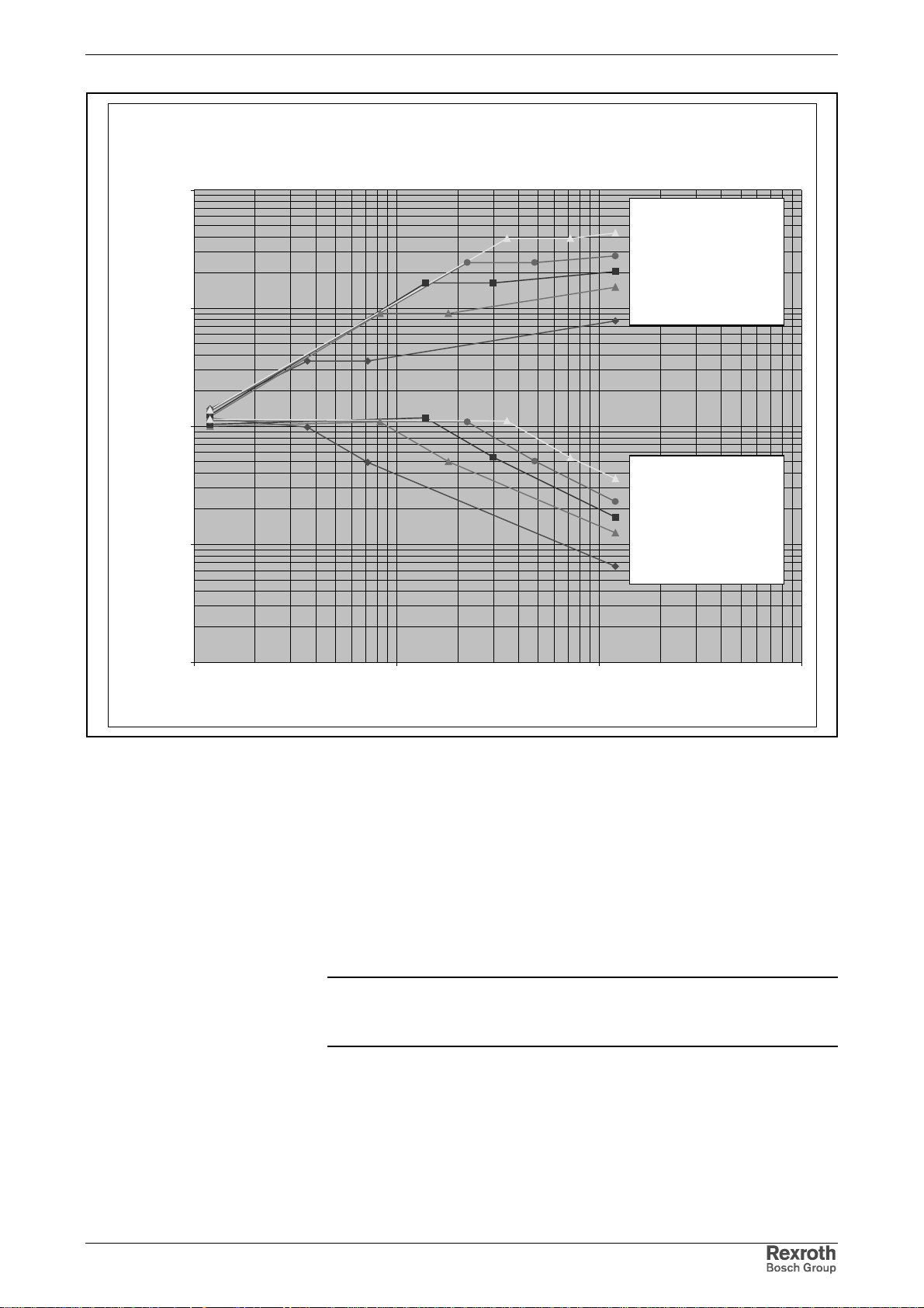
Rexroth IndraDrive Electrical Data 5-25
Braking resistors for HCS03 ... 0210
Peak power P_s and Energy absorption W
10000
W [kWs]
1000
P_s [kW]
100
10
Energy
HLR01.1N-36K0-N05R4
HLR01.1N-23K0-N05R5
HLR01.1N-17K0-N05R1
HLR01.1N-12K5-N05R5
HLR01.1N-06K5-N06R1
Power
HLR01.1N-36K0-N05R4
HLR01.1N-23K0-N05R5
HLR01.1N-17K0-N05R1
HLR01.1N-12K5-N05R5
HLR01.1N-06K5-N06R1
1
1 10 100 1000
Duty cycle [s]
Fig. 5-36: Selection aid for braking resistors for HCS03.1E-W0210
Line Cross Sections for Reinforced Braking Resistors
HLR01.1
According to the standards "Electronic equipment for use in power
installations" (EN 50178, chapter 5.3.2.1) and "Adjus table s peed elec tric al
power drive systems" (EN 61800-5-1, chapter 4.2.5.4.2), a stationary
connection of the equipment grounding conductor is required. The
following requirement has to be complied with: cross section of equipment
grounding conductor at least 10 mm
Note: For the equipment grounding conductor run lines with a cross
section corresponding to that of the lines for mains connection
at the drive controller HCS and having at least 10 mm
Requirements for line routing:
• The cross sections are valid for one phase each in the case of
stranded wires and are specified according to the regulations of
VDE0298.
2
• Up to 50 mm
, solid wires in the cable duct.
2
(mechanical stability).
2
.
DOK-INDRV*-FU*********-IB01-EN-P
Page 76
5-26 Electrical Data Rexroth IndraDrive
out_max
Motor Filter HMF
Motor filter I
[A]
N
P
V
[W]
L
M
[µH]
f
out_max
[Hz]
f
p_max
[kHz]
du/dt at
output
U
[kV]
[kV / us]
HMF01.1A-N0K2-D0045-A-500-NNNN 45 120 3 x 160 200 4 < 1 1,2
HMF01.1A-N0K2-D0073-A-500-NNNN 73 160 3 x 100 200 4 < 1 1,2
HMF01.1A-N0K2-D0095-A-500-NNNN 95 190 3 x 78 200 4 < 1 1,2
HMF01.1A-N0K2-D0145-A-500-NNNN 145 220 3 x 50 200 4 < 1 1,2
Fig. 5-37: Electrical data
Motor filter Cross section
[mm²]
Cross section
flexible
[mm²]
Cross section
[AWG]
Tightening
torque
[Nm]
HMF01.1A-N0K2-D0045-A-500-NNNN 16 - 6 1,5
HMF01.1A-N0K2-D0073-A-500-NNNN 35 - 2 6
HMF01.1A-N0K2-D0095-A-500-NNNN 50 2*25 0 6
HMF01.1A-N0K2-D0145-A-500-NNNN 95 2*50 4/0 25
Fig. 5-38: Terminal connector data
DOK-INDRV*-FU*********-IB01-EN-P
Page 77
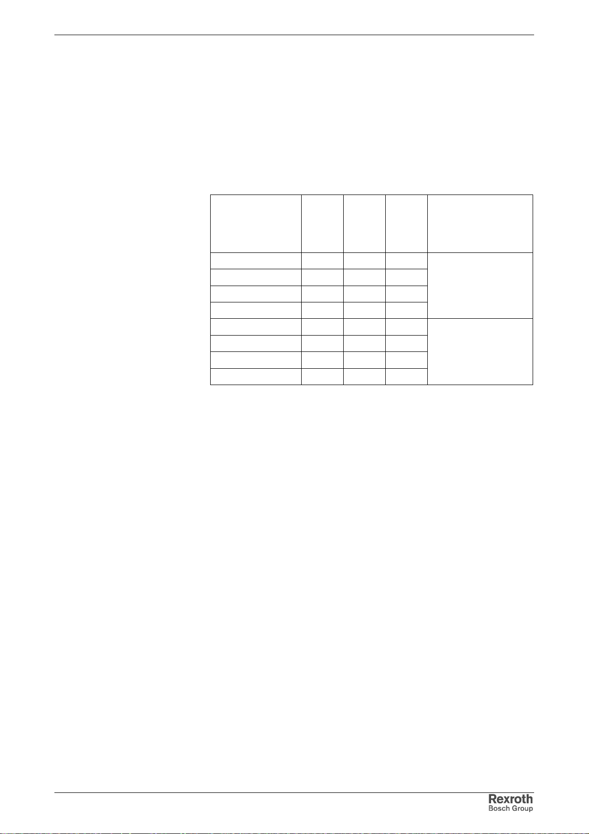
Rexroth IndraDrive Mounting and Installation 6-1
6 Mounting and Installation
6.1 Mounting
Dimensions – Power Sections
Device Depths, Heights and Widths
Min.
moun-
Device Device
width
[mm]
HCS02.1E-W0012 65 70 290
HCS02.1E-W0028 65 70 352
HCS02.1E-W0054 105 110 352
HCS02.1E-W0070 105 110 352
HCS03.1E-W0070 125 125 440
HCS03.1E-W0100 225 225 440
HCS03.1E-W0150 225 225 440
HCS03.1E-W0210 350 350 440
1) incl. minimum distance between the components
2) device body without mounting flange on top and bottom, as well as
minimum distances for ventilation and installation
3) incl. touch guard, connector housing, bending radius of fiber optic
cable, control panel "C"
Fig. 6-1: Mounting dimensions
ting
width
[mm] 1)
Device
height
[mm] 2)
Device depth
[mm] 3)
265
for control cabinets with
at least 300 mm of
depth
322
for control cabinets with
at least 400 mm of
depth
DOK-INDRV*-FU*********-IB01-EN-P
Page 78
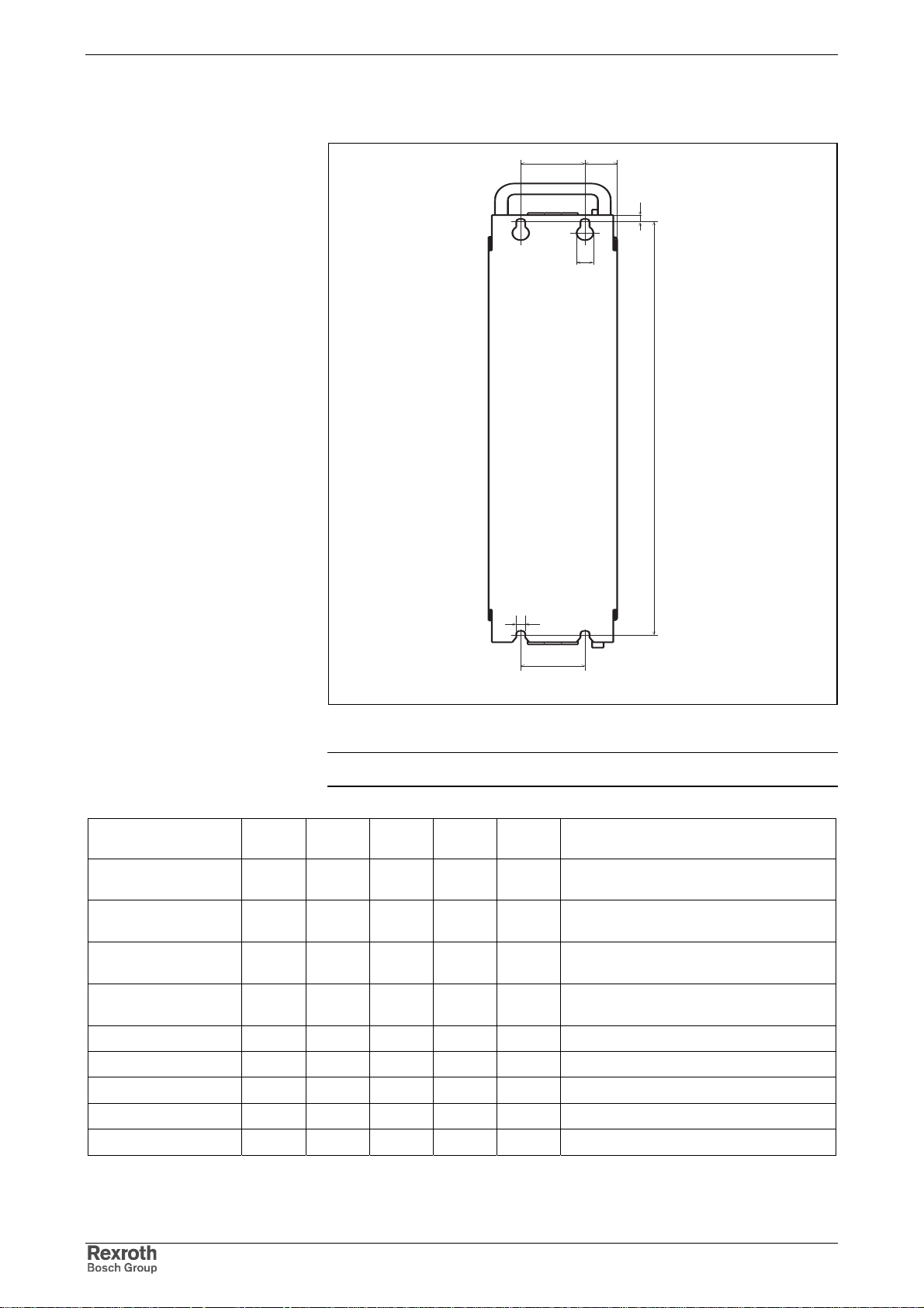
6-2 Mounting and Installation Rexroth IndraDrive
Drilling Pattern for the Mounting Plate
MK
N
P
L
Fig. 6-2: Drilling pattern
Note: The figure shows the back of the devices.
Device
HCS02.1E-W0012 0 316 32,5 13 7
HCS02.1E-W0028 0 378 32,5 13 7
HCS02.1E-W0054 55 378 25 13 7
HCS02.1E-W0070 55 378 25 13 7
HCS03.1E-W0070 75 466 25 13 7
HCS03.1E-W0100 175 466 25 13 7
HCS03.1E-W0150 175 466 25 13 7
HCS03.1E-W0210 250 466 50 13 7
HNL02.1 100 378 20 13 7
K
[mm]L[mm]M[mm]P[mm]R[mm]
R
K
HNF_bohrbild.fh7
Notes
observe additional distance to lateral
neighboring devices
observe additional distance to lateral
neighboring devices
observe additional distance to lateral
neighboring devices
observe additional distance to lateral
neighboring devices
Fig. 6-3: Drilling pattern
DOK-INDRV*-FU*********-IB01-EN-P
Page 79
Rexroth IndraDrive Mounting and Installation 6-3
Distances for Drive Controllers
In addition to the mounting dimensions, the components of the
Rexroth IndraDrive range require additional mounting clearance
• to ventilate the components
• to mount accessories and connections
• to take temperature limits of neighboring mounting parts, such as
cable ducts etc., into account
To determine the required mounting clearances in the control cabinet,
take additional distances between the components and on their tops and
bottoms into account.
Distance between Drive Controllers
Owing to power dissipation in the components, espec ially due to installed
braking resistors in compact devices, the temperatures of neighboring
components are rising. In the case of lateral mounting, trouble-free
operation therefore requires the following minimum distances in [mm]
between the components.
tofrom
HCS02 HCS03 (HNK01,
HLR01)
HCS02.1E 5 -HCS03.1E with HNK01 and HLR01 -- 0
-- not allowed
Fig. 6-4: Minimum distance in [mm]
Note: For arrangement of the components in the control cabinet,
take their dimension sheets and the required minimum
distances into account.
DOK-INDRV*-FU*********-IB01-EN-P
Page 80
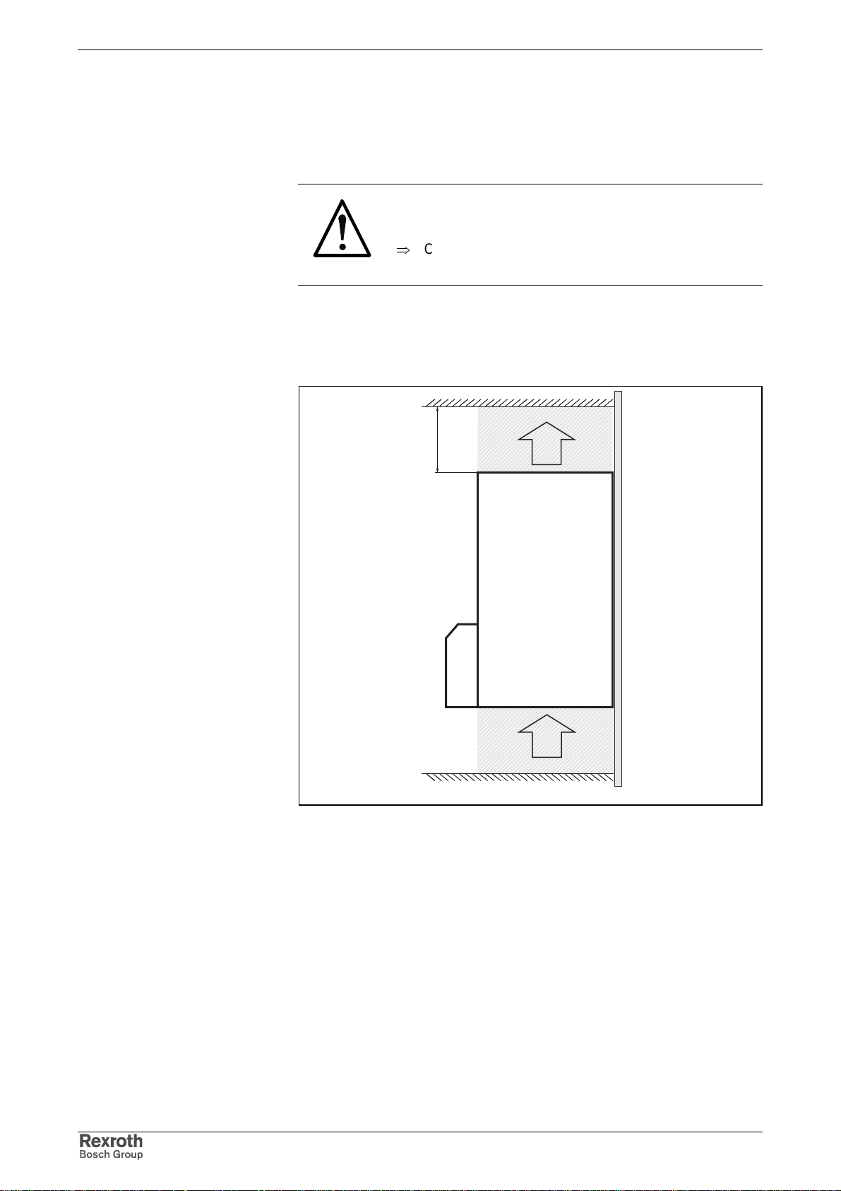
6-4 Mounting and Installation Rexroth IndraDrive
Distances on Top and Bottom of Components
Owing to power dissipation in the components, the temperature of the
cooling air current at the device outlet is rising to values higher than
ambient temperature at device inlet.
Property damage due to temperatures higher
than 105 °C!
⇒
Comply with indicated minimum distances!
CAUTION
In order that drive controllers can discharge the power dissipation
generated inside of them, they need space on their top (A) and
bottom (B).
d
B
A
A: air intake
B: air outlet
C: mounting surface in control cabinet
d: distance to top of device
Fig. 6-5: Air intake and air outlet at drive controller
C
kuehlluft.FH7
DOK-INDRV*-FU*********-IB01-EN-P
Page 81
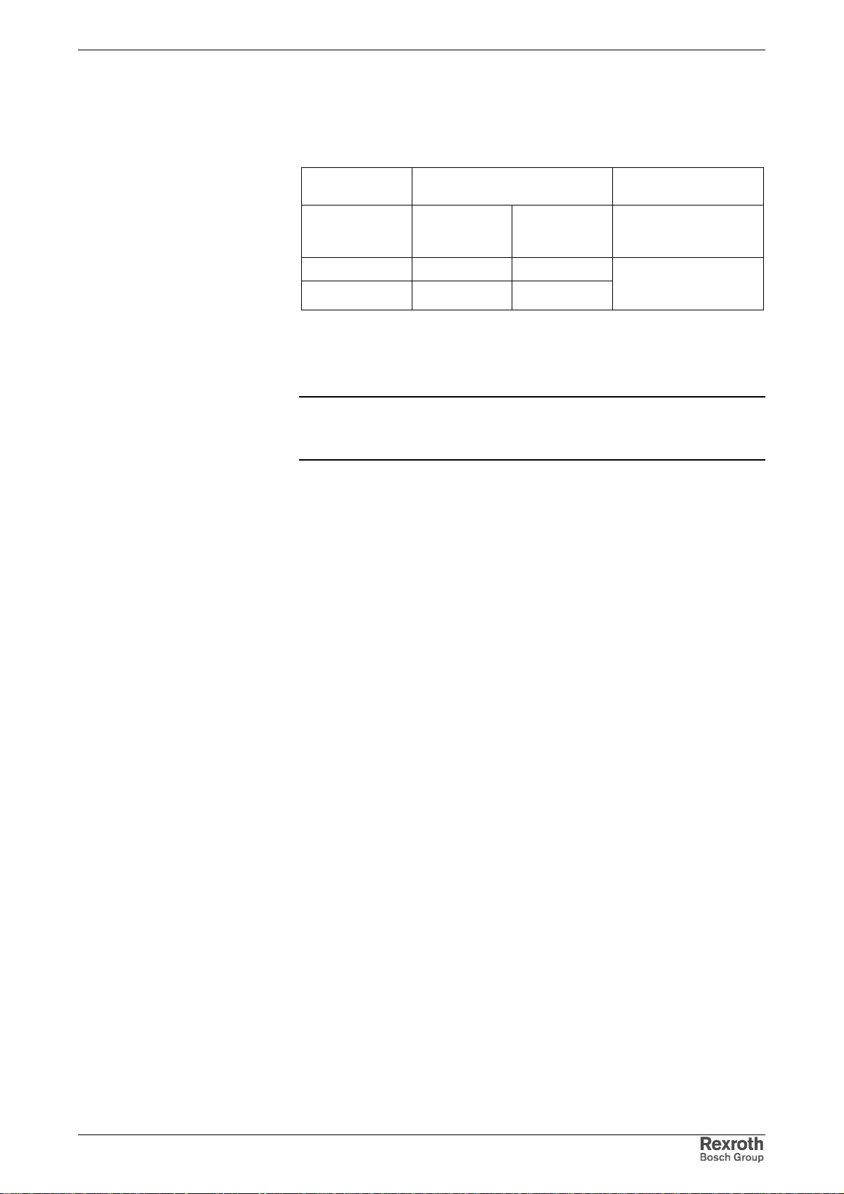
Rexroth IndraDrive Mounting and Installation 6-5
Minimum distance for ventilation
For sufficient ventilation of the com ponents you have to comply with the
minimum distances below. At components without integrated braking
resistor, there will be temperatures of up to 105 °C at the air outlet (B)
(with an air intake temperature of 45 °C).
Component Minimum distance for
ventilation
at the bottom
(A)
[mm] 1)
HCS02 80 80
HCS03 100 80
1) for additional mounting parts, such as HAS, see dimensional
drawings
2) integrated braking resistors require additional distance
Fig. 6-6: Minimum distance for ventilation
at the top
(B)
[mm] 2)
Notes
additionally take power
at braking resistor into
account
Note: If there are different minimum distances for the individual
components in a drive system, the greates t value determines
the minimum distance to be observed.
Minimum Distance to Braking
Resistor
For components with integrated braking resistor (supply units, DC bus
resistor units, HCS02 drive controllers) their higher outlet temperatures
have to be taken into account.
To determine the required dist ances the res ulting outlet tem peratures are
indicated in diagrams in the technical data of the components.
Input value in the diagrams is the generated power of the braking
resistors or the individual output current. See exemplary diagram below:
DOK-INDRV*-FU*********-IB01-EN-P
Page 82
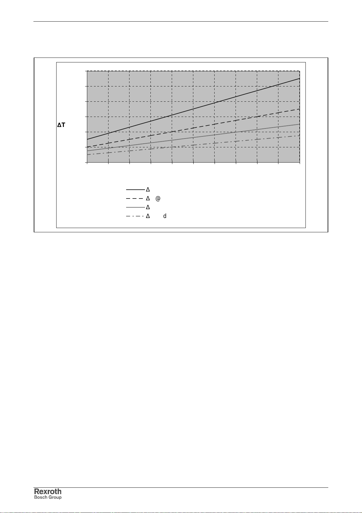
6-6 Mounting and Installation Rexroth IndraDrive
Input value in the diagrams is the generated power of the braking
resistors or the individual output current. See exemplary diagram below:
120
100
80
60
∆
T [K]
40
20
0
0 50 100 150 200 250 300 350 400 450 500
P
[W]
BD
∆
T @ d~0mm
∆
T @ d~40mm
∆
T @ d~80mm
∆
T @ d~120mm
PBD: average continuous braking resistor power
d: distance to top of device
Fig. 6-7: Exemplary diagram
The minimum distance for these mounting parts results from the
intersection of the input value with the allowed temperature rise.
DOK-INDRV*-FU*********-IB01-EN-P
Page 83
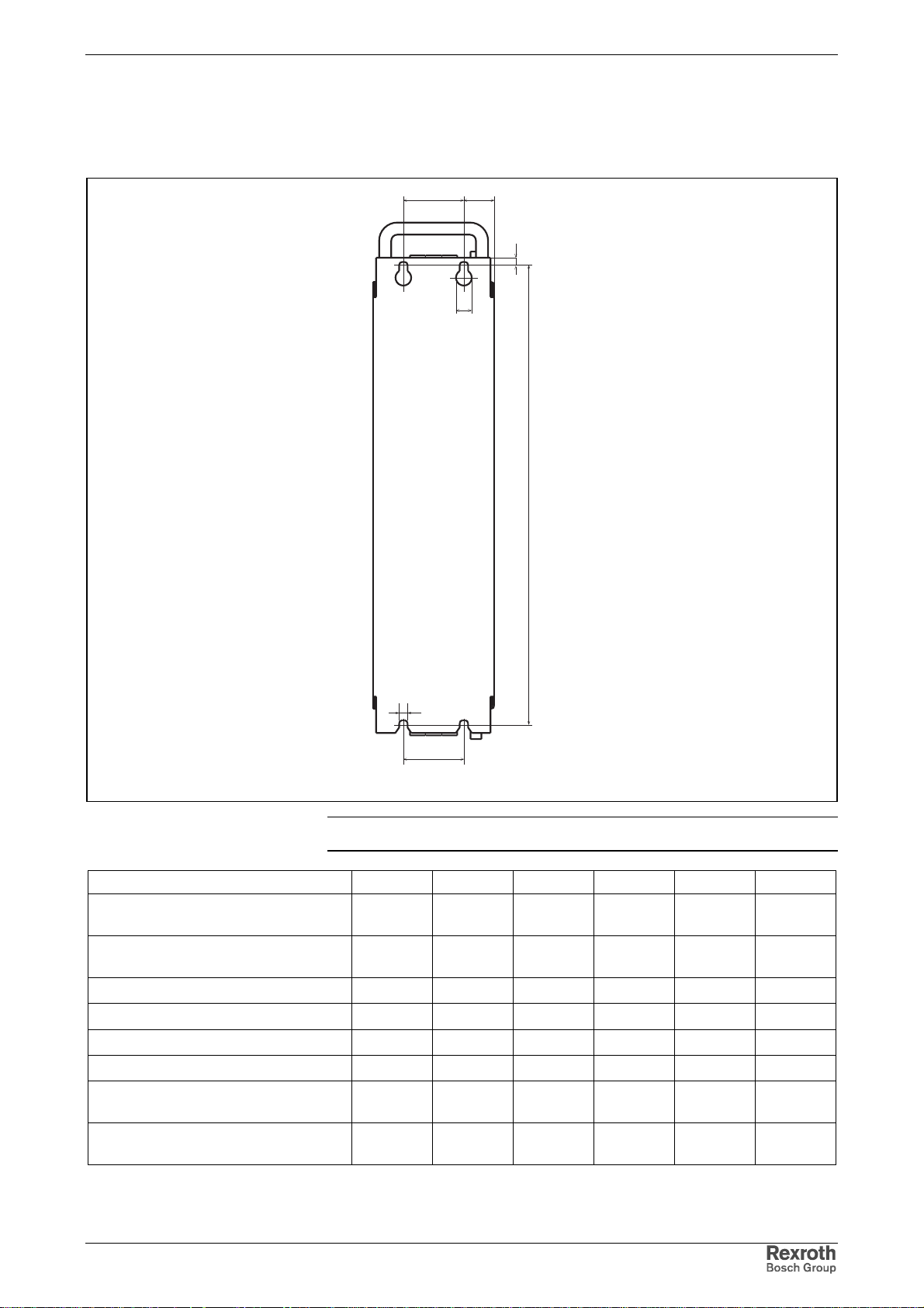
Rexroth IndraDrive Mounting and Installation 6-7
Dimensions – Mains Filter HNF
Drilling Pattern
MK
N
P
L
R
K
HNF_bohrbild.fh7
Note: The figure shows the back of the devices.
Mains filter K [mm] L [mm] M [mm] N [mm] P [mm] R [mm]
HNF01.1A-F240-E0051-A-480-NNNN
HNF01.1A-M900-E0051-A-480-NNNN
HNF01.1A-F240-E0125-A-480-NNNN
HNF01.1A-M900-E0125-A-480-NNNN
HNF01.1A-F240-E0202-A-480-NNNN 125 466 12,5 7 13 6,5
HNF01.1A-M900-E0202-A-480-NNNN 150 466 50 7 13 6,5
HNF01.1A-F240-R0026-A-480-NNNN 50 466 25 7 13 6,5
HNF01.1A-M900-R0026-A-480-NNNN 100 466 25 7 13 6,5
HNF01.1A-F240-R0065-A-480-NNNN
HNF01.1A-M900-R0065-A-480-NNNN
HNF01.1A-F240-R0094-A-480-NNNN
HNF01.1A-M900-R0094-A-480-NNNN
50 466 25 7 13 6,5
125 466 12,5 7 13 6,5
100 466 25 7 13 6,5
125 466 12,5 7 13 6,5
DOK-INDRV*-FU*********-IB01-EN-P
Fig. 6-8: Drilling pattern
Page 84
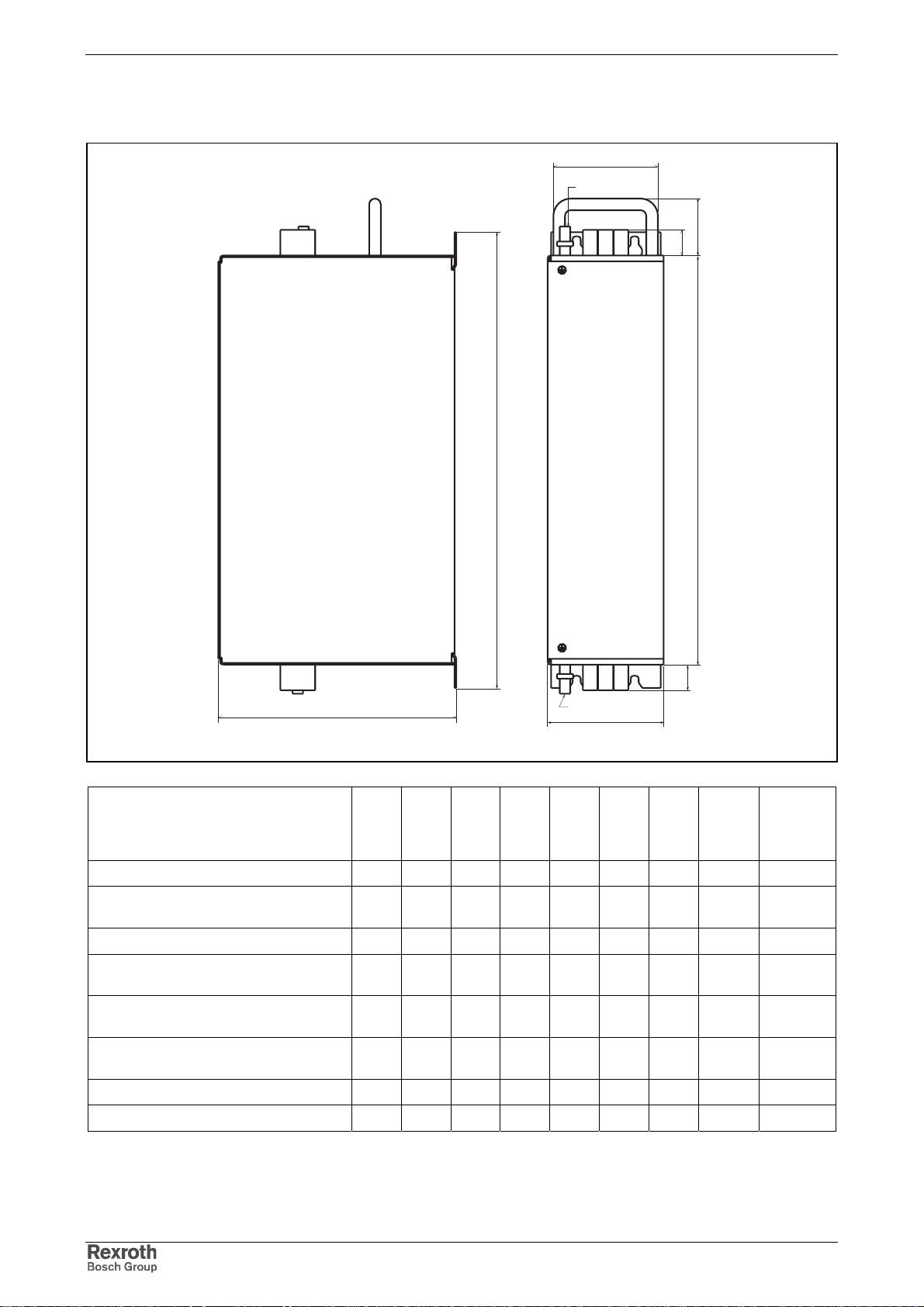
6-8 Mounting and Installation Rexroth IndraDrive
Dimensions
F
H
E
L1L2L3
G
X3
Netz
Line
A
D
Last
Load
X3.2
L1.1
L2.1
L3.1
B
Mains filter A
[mm]B[mm]C[mm]D[mm]E[mm]F[mm]G[mm]
HNF01.1A-F240-R0026-A-480-NNNN 480 262 100 440 - - 26 M6x20 8.6
HNF01.1A-F240-E0051-A-480-NNNN
HNF01.1A-M900-E0051-A-480-NNNN
HNF01.1A-M900-R0026-A-480-NNNN 480 262 150 440 - - 26 M6x20 8.6
HNF01.1A-F240-R0065-A-480-NNNN
HNF01.1A-M900-R0065-A-480-NNNN
HNF01.1A-F240-R0094-A-480-NNNN
HNF01.1A-M900-R0094-A-480-NNNN
HNF01.1A-F240-E0125-A-480-NNNN
HNF01.1A-M900-E0125-A-480-NNNN
HNF01.1A-F240-E0202-A-480-NNNN 480 262 150 440 40 110 63.5 M10x30 25
HNF01.1A-M900-E0202-A-480-NNNN 480 262 250 440 40 110 63.5 M10x30 25
480 262 100 440 - - 33
480 262 150 440 40 110 40
480 262 150 440 40 110 45
480 262 150 440 40 110 45
H
C
HNF_abmessungen.fh7
G
M6x16
M6x16
M10x30
M10x30
H max.
tightening
torque
[Nm]
2.3
4.8
25
25
Fig. 6-9: Dimensions
DOK-INDRV*-FU*********-IB01-EN-P
Page 85
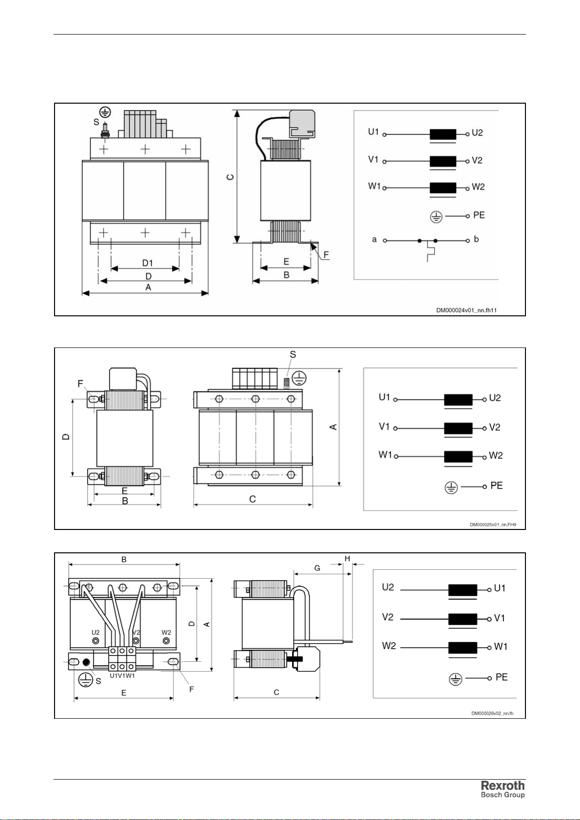
Rexroth IndraDrive Mounting and Installation 6-9
Dimensions – Mains Choke HNL01.1E (infeeding)
Dimensions Type 1:
Dimensions Type 2:
Dimensions Type 3:
DOK-INDRV*-FU*********-IB01-EN-P
Page 86
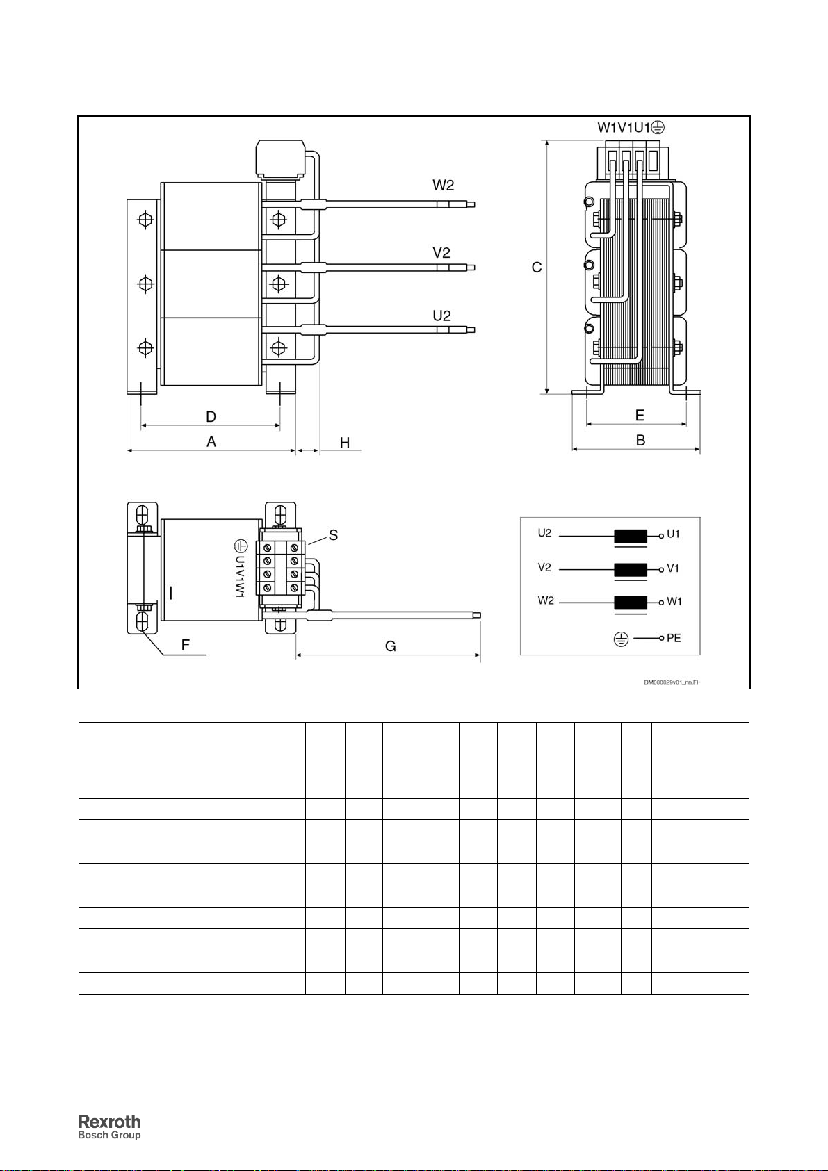
6-10 Mounting and Installation Rexroth IndraDrive
Dimensions Type 4:
Mains choke Type
HNL01.1E-1000-N0012-A-500-NNNN 1 120 61 164 81 - 44 6,4 x 11 2,7
HNL01.1E-1000-N0020-A-500-NNNN 1 150 66,5 184 113 - 49,5 6,4 x 11 3,8
HNL01.1E-0600-N0032-A-500-NNNN 1 150 66,5 185 113 - 49,5 6,4 x 11 4,5
HNL01.1E-0571-N0050-A-500-NNNN 4 153 100 238 127 - 80 8,5 x 12 400 30 13
HNL01.1E-0400-N0051-A-480-NNNN 1 180 112 225 125 80 87 7 x 15 13,5
HNL01.1E-0362-N0080-A-500-NNNN 3 175 205 180 145 - 185 8,5 x 12 350 ca. 12 13
HNL01.1E-0240-N0106-A-500-NNNN 3 193 205 210 145 - 185 8,5 x 12 380 ca. 12 15
HNL01.1E-0200-N0125-A-480-NNNN 1 230 148 295 180 - 122 8 x 12 24
HNL01.1E-0170-N0146-A-500-NNNN 3 205 250 230 152 - 230 8,5 x 12 400 ca. 12 22
HNL01.1E-0100-N0202-A-480-NNNN 1 265 152 350 215 - 126 15 x 11 33
Dim.
[mm]
ABCDD1EF
1)
Weight
[kg]
GH
1) long hole in "B" direction
Fig. 6-10: Mechanical data HNL
DOK-INDRV*-FU*********-IB01-EN-P
Page 87
Rexroth IndraDrive Mounting and Installation 6-11
Mains Choke U
[V]
N
I
N
[A]
L
N
[µH]
P
[W]
V
I
max
[A]
at I
L
min
max
Connection
Cross Section
[mm²]
HNL01.1E-1000-N0012-A-500-NNNN 500 12 3 x 1000 40 25 50% of L
HNL01.1E-1000-N0020-A-500-NNNN 500 20 3 x 1000 60 50 50% of L
HNL01.1E-0600-N0032-A-500-NNNN 500 32 3 x 600 75 80 50% of L
HNL01.1E-0571-N0050-A-500-NNNN 500 50 3 x 571 50 100 50% of L
N
N
N
N
4 (a, b: 4)
6 (a, b: 4)
10 (a, b: 4)
16 (a, b: -)
AWG 8
HNL01.1E-0400-N0051-A-480-NNNN 480 51 3 x 400 165 77 50% of LN16 (a, b: 2,5)
HNL01.1E-0362-N0080-A-500-NNNN 500 80 3 x 362 80 160 50% of L
N
35 (a, b: -)
AWG 6
HNL01.1E-0240-N0106-A-500-NNNN 500 106 3 x 240 100 212 50% of L
N
35 (a, b: -)
AWG 1/0
HNL01.1E-0200-N0125-A-480-NNNN 480 125 3 x 200 170 188 50% of LN70 (a, b: 2,5)
HNL01.1E-0170-N0146-A-500-NNNN 500 146 3 x 170 130 292 50% of L
N
50 (a, b: -)
AWG 1/0
HNL01.1E-0100-N0202-A-480-NNNN 480 202 3 x 100 200 303 50% of LN150 (a, b: 2,5)
Fig. 6-11: Electrical data HNL
Temperature Contact a, b
Switching Capacity
Switching Temperature
1 A / AC 250 V; DC 24 V
125 °C
Note: HNL01.1E mains chokes of type 1 are equipped with a
temperature contact (a, b), types 2, 3 and 4 are not.
DOK-INDRV*-FU*********-IB01-EN-P
Page 88
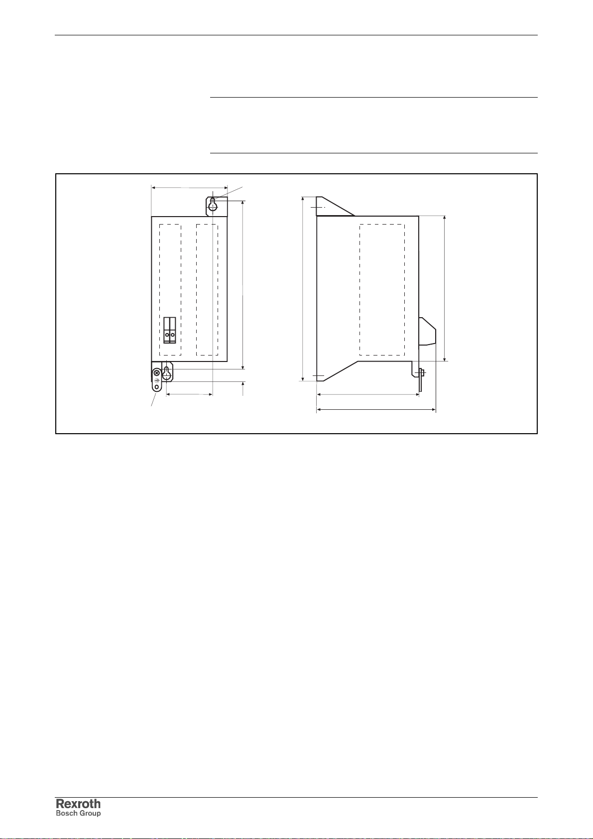
6-12 Mounting and Installation Rexroth IndraDrive
Dimensions – Standard Braking Resistors HLR01.1
Note: The standard braking resistors are intended to be mounted
above the drive controllers HCS03; otherwise, forced
convection (blower) with a volume stream of 200 m ³/hour is to
be provided.
1)
12
123
75
(M6)
275
19,5
Fig. 6-12: Dimensional drawing braking resistor HLR01.1N-0300-N17R5-A-
007-NNNN
300
165
196
MBZU0032EN00.FH9
235
DOK-INDRV*-FU*********-IB01-EN-P
Page 89
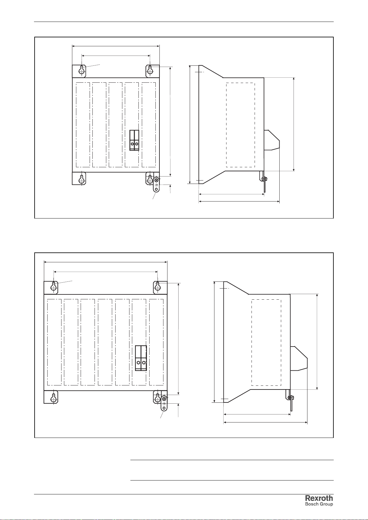
Rexroth IndraDrive Mounting and Installation 6-13
223
175
(M6)
(M6)
350
300
275
12
19,5
300
165
210
1)
Fig. 6-13: Dimensional drawing braking resistor
HLR01.1N-0470-N11R7-A-007-NNNN and
HLR01.1N-0780-N07R0-A-007-NNNN
235
MBZU0033EN00.FH9
DOK-INDRV*-FU*********-IB01-EN-P
275
12
19,5
300
235
165
220
1)
MBZU0048EN00.FH9
Fig. 6-14: Dimensional drawing braking resistor HLR01.1N-1K08-N05R0-A-
007-NNNN
Note: The joint bar (ground strap) is contained in the s c ope of s upply
of the standard braking resistors HLR01.
Page 90
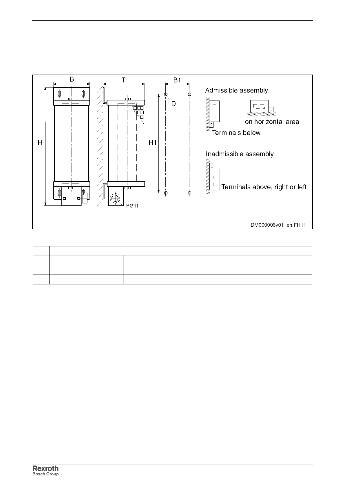
6-14 Mounting and Installation Rexroth IndraDrive
Dimensions – Reinforced Braking Resistors HLR01.1
Fixed Resistors IP 20 Type A
Fig. 6-15:Type A5 – A6
Type Dimensions in mm Weight in kg
HBTH1B1D
A5 586 185 120 526 150 M6 5,2
A6 686 185 120 626 150 M6 6,2
Fig. 6-16: Dimensions table braking resistor type A
DOK-INDRV*-FU*********-IB01-EN-P
Page 91
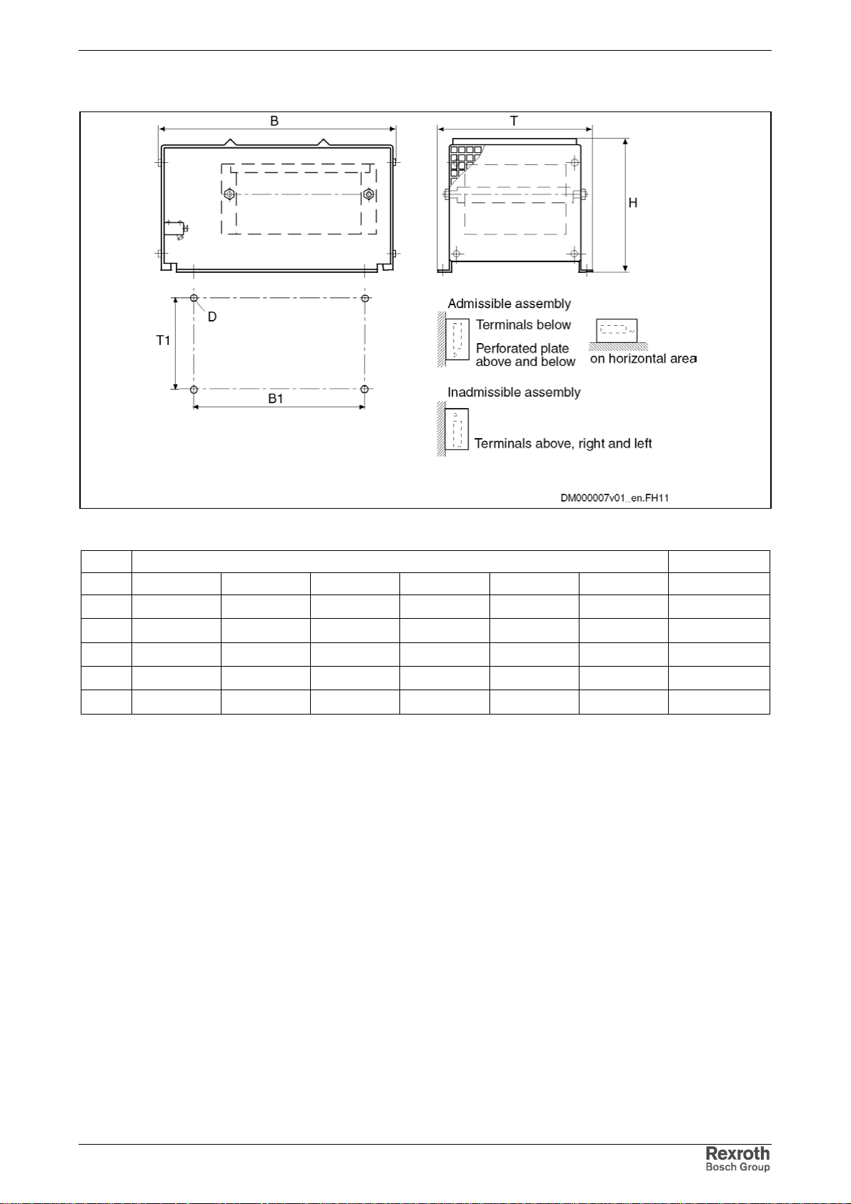
Rexroth IndraDrive Mounting and Installation 6-15
Steel Grid Fixed Resistors IP 20 Type B
Fig.: 6-17 Type B1 – B4
Type Dimensions in mm Weight in kg
BTHB1T1D
B1 490 300 270 380 270 M10 9,5
B2 490 400 270 380 370 M10 13
B3 490 600 270 380 570 M10 22
B4 490 800 270 380 770 M10 33
B5 490 1000 270 380 970 M10 44
Tab.: 6-1 Dimensions table braking resistor type B
DOK-INDRV*-FU*********-IB01-EN-P
Page 92
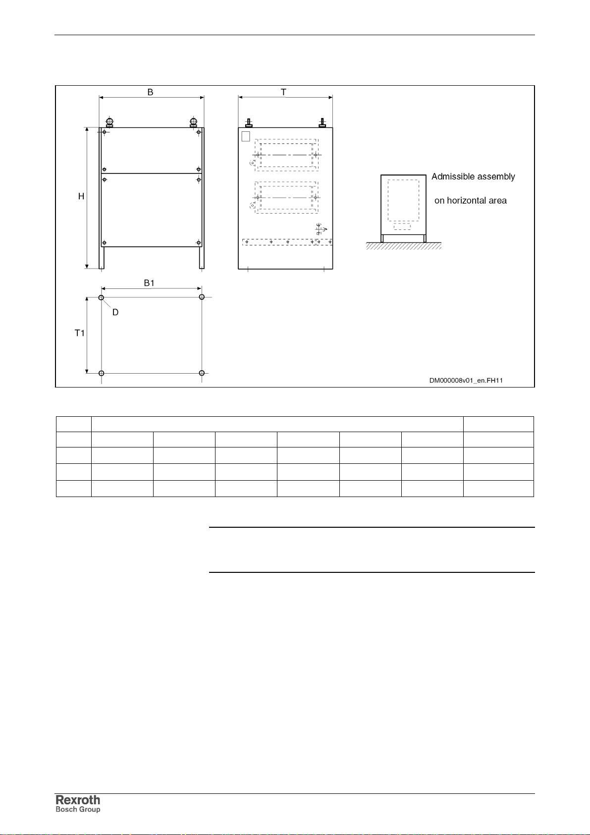
6-16 Mounting and Installation Rexroth IndraDrive
Steel Grid Fixed Resistors IP 20 Type C
Fig.: 6-18 Type C1 – C7
Type Dimensions in mm Weight in kg
BTHB1T1D
C2 595 490 710 570 380 M10 56
C3 795 490 710 770 380 M10 80
C4 995 490 710 970 380 M10 93
Tab.: 6-2 Dimensions table braking resistor type C
Note: Under consideration of the technical data for the minimum
braking resistance and the brake chopper, other braking
resistors can be used alternatively.
DOK-INDRV*-FU*********-IB01-EN-P
Page 93
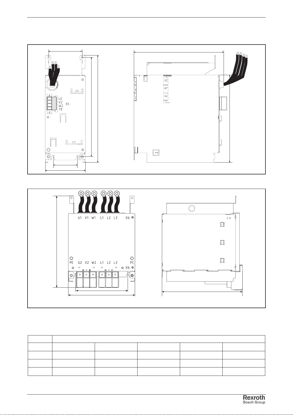
Rexroth IndraDrive Mounting and Installation 6-17
Dimensions – Motor Filt er HMF
U2 V2 W2 PE
104
75
125
277
305
330
MBZU0064EN00.FH9
Fig. 6-19: Dimens ions motor filter HMF01.1A-N0K2-D0045-A-500-NNNN
270
H
B1
B
T
MBZU0056EN00.fh9
Fig. 6-20: Dimens ions motor filter HMF01.1A-N0K2-D0073-A-500-NNNN,
HMF01.1A-N0K2-D0095-A-500-NNNN and
HMF01.1A-N0K2-D0145-A-500-NNNN
Type Dimensions in mm
BHTB1
H1
0073 225 315 270 175 257
0095 225 315 270 175 257
0145 350 400 260 250 310
Fig. 6-21: Dimensions motor filter
DOK-INDRV*-FU*********-IB01-EN-P
Page 94
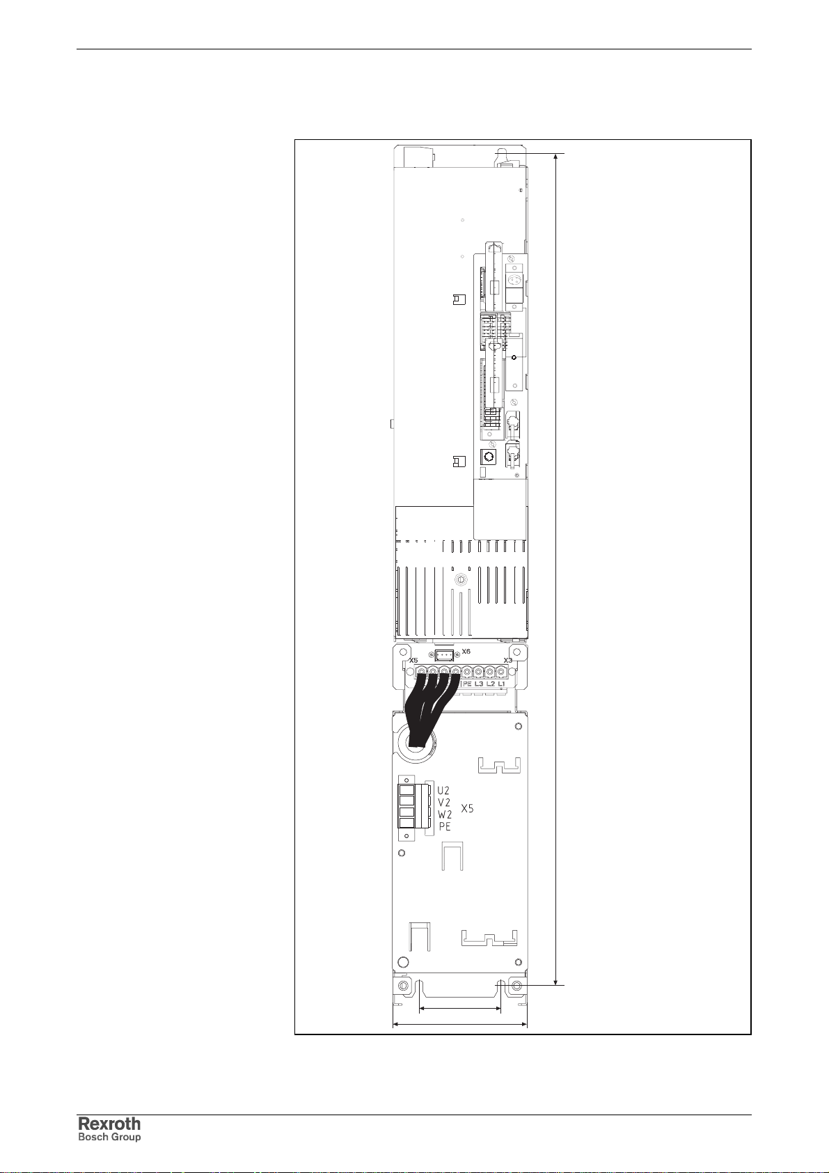
6-18 Mounting and Installation Rexroth IndraDrive
Arrangement of the Components HCS03.1 /
Motor Filter HMF
U2 V2 W2 PE
770
75
125
MBZU0066EN00.FH9
Fig. 6-22: Sample mounting HCS03.1E-W0070 / HMF01.1A-N0K2-D0045
DOK-INDRV*-FU*********-IB01-EN-P
Page 95
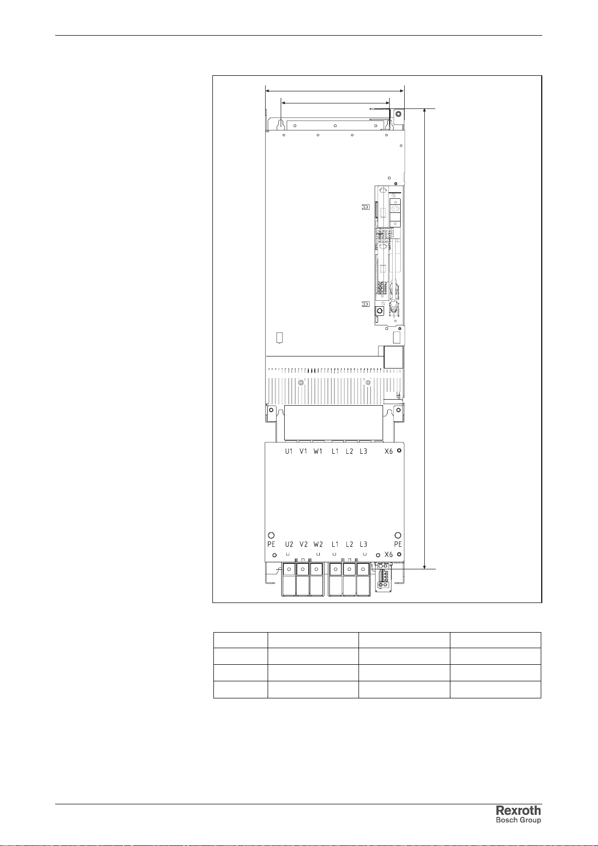
Rexroth IndraDrive Mounting and Installation 6-19
B
B1
H
MBZU0057EN00.FH9
Fig. 6-23: Sample mounting HCS03.1E-W0100 0150 0210 / motor filter
DOK-INDRV*-FU*********-IB01-EN-P
HCS03.1E- H B B1
W0100 720 225 175
W0150 720 225 175
W0210 780 350 250
Fig. 6-24: Dimensions table for sample mounting HCS03.1E-…/ motor filter
HMF
Page 96
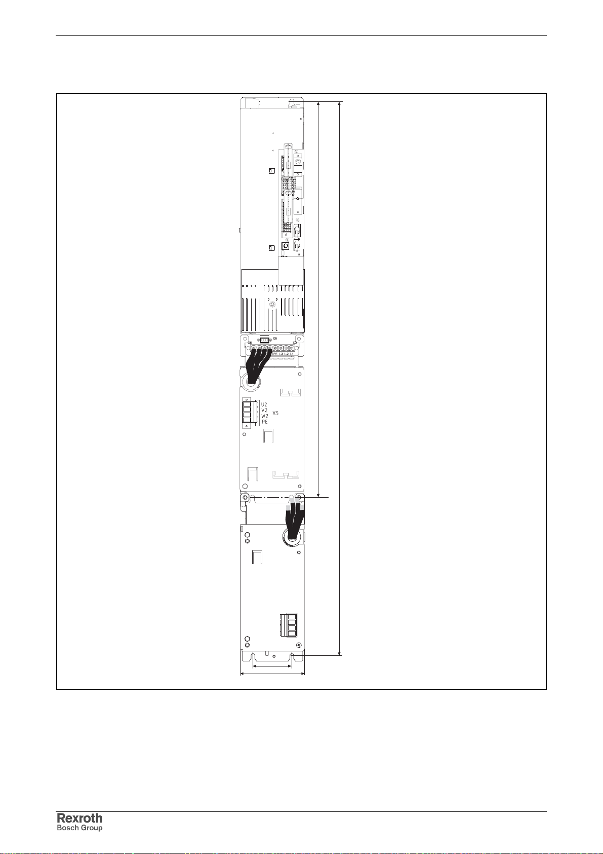
6-20 Mounting and Installation Rexroth IndraDrive
Arrangement of the Components HCS03.1 / Motor Filter
and Mains Filter
770
1075
U2 V2 W2 PE
PE
PE
L3
X3
L2
L1 L2 L3 PE
L1
PE
75
125
MBZU0067EN00.FH9
Fig. 6-25: Arrangement HCS03.1E-W0070 / motor filter and mains filter
+ HAS05.1-001 + HAS05.1-002
DOK-INDRV*-FU*********-IB01-EN-P
Page 97
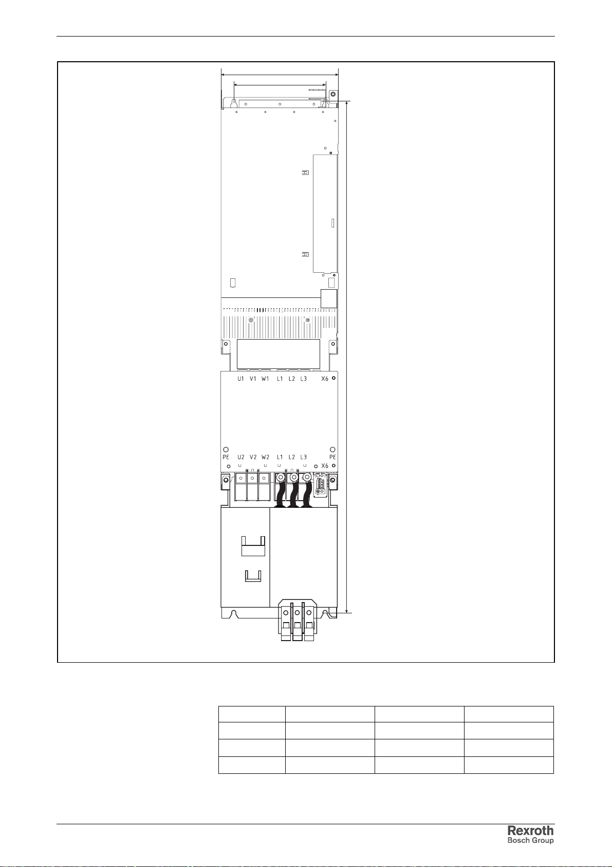
Rexroth IndraDrive Mounting and Installation 6-21
B
B1
H
DOK-INDRV*-FU*********-IB01-EN-P
MBZU0068EN00.FH9
Fig. 6-26: Arrangement of device 0100, 0150, 0210 / motor filter and mains
filter
HCS03.1E- H B1 B
W0100 980 175 225
W0150 980 175 225
W0210 1090 250 350
Fig. 6-27: Dimensions table for sample mounting HCS03.1E-.. / mains filter /
motor filter
Page 98
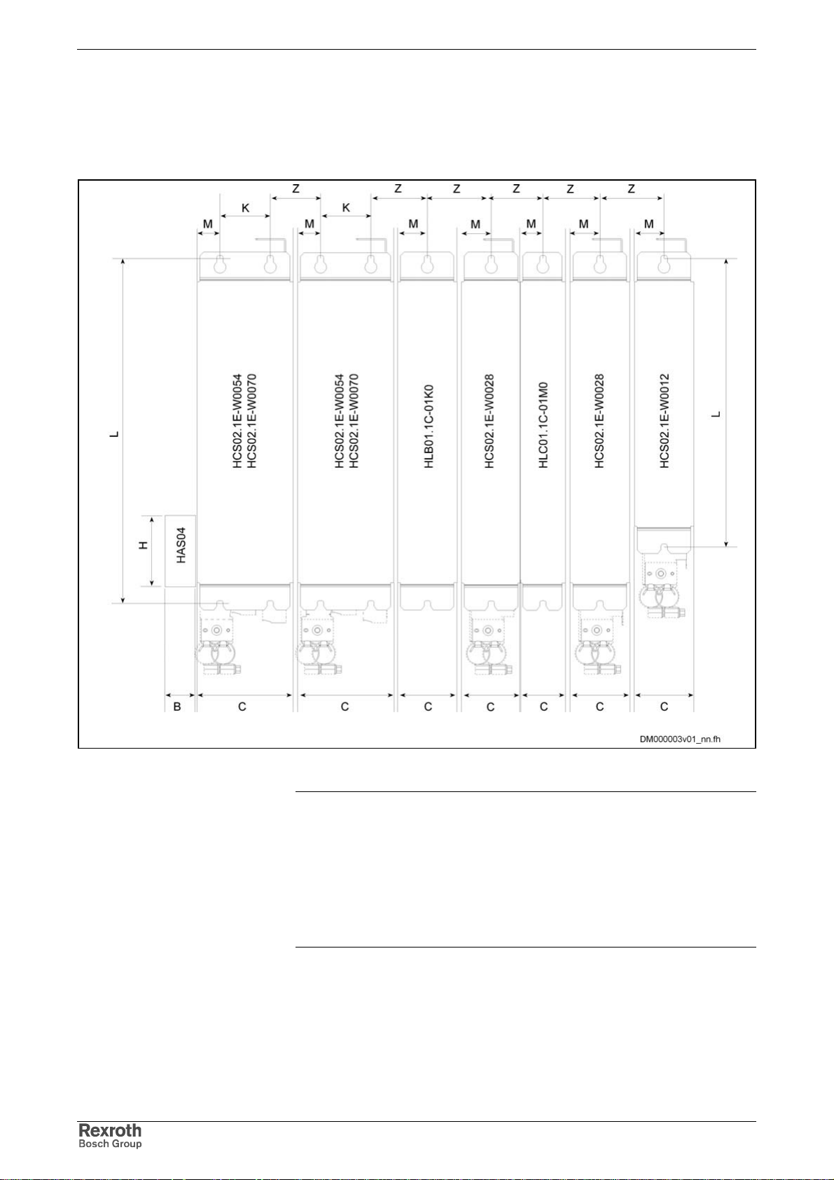
6-22 Mounting and Installation Rexroth IndraDrive
Combination of Drive Controllers of the Rexroth IndraDrive C Product Range
Fig. 6-28: Rexroth IndraDrive C components
Note: Observe that using HAS04 accessory at the HCS arranged at
the utmost left position requires additional space of 30 mm.
Rexroth IndraDrive components are arranged in line to the
right starting from the supplying device. Arrange the drive
controllers with high capacity as close to the supplying unit as
possible.
The HAS02 accessories in the figure require additional
mounting clearance.
DOK-INDRV*-FU*********-IB01-EN-P
Page 99
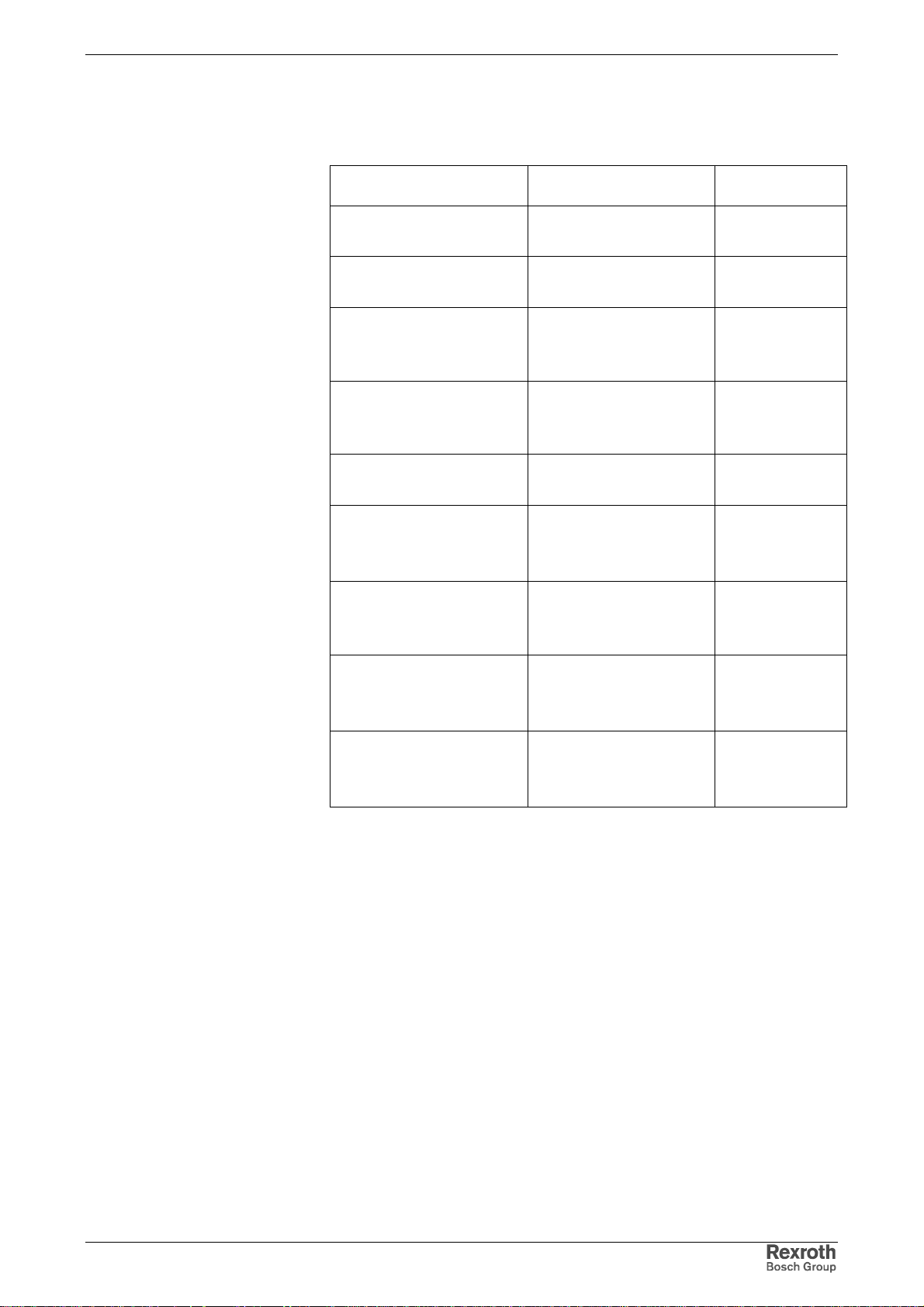
Rexroth IndraDrive Mounting and Installation 6-23
Dimension Z is significantly determined by the involved components. The
table below contains the dimensions Z between the component ar ranged
to the left and the component arranged to the right.
Component left Component right
HCS02.1E-W0012
HCS02.1E-W0028
HCS02.1E-W0054
HCS02.1E-W0070
HCS02.1E-W0054
HCS02.1E-W0070
HCS02.1E-W0012
HCS02.1E-W0028
HCS02.1E-W0054
HCS02.1E-W0070
HCS03.1E-W0070
HCS03.1E-W0100
HCS03.1E-W0150
HCS03.1E-W0210 HCS03.1E-W0210
HCS03.1E-W0070
HCS03.1E-W0100
HCS03.1E-W0150
HCS03.1E-W0210
HCS02.1E-W0012
HCS02.1E-W0028
HCS02.1E-W0054
HCS02.1E-W0070
HCS02.1E-W0012
HCS02.1E-W0028
HCS03.1E-W0070
HCS03.1E-W0100
HCS03.1E-W0150
HCS03.1E-W0210
HCS03.1E-W0070
HCS03.1E-W0100
HCS03.1E-W0150
Dimension Z
[mm]
70
55
50
(without distance
between the
components)
57,5
(without distance
between the
components)
62,5
50
(without distance
between the
components)
100
(without distance
between the
components)
75
(without distance
between the
components)
75
(without distance
between the
components)
DOK-INDRV*-FU*********-IB01-EN-P
Fig. 6-29: Table for dimension Z
Page 100
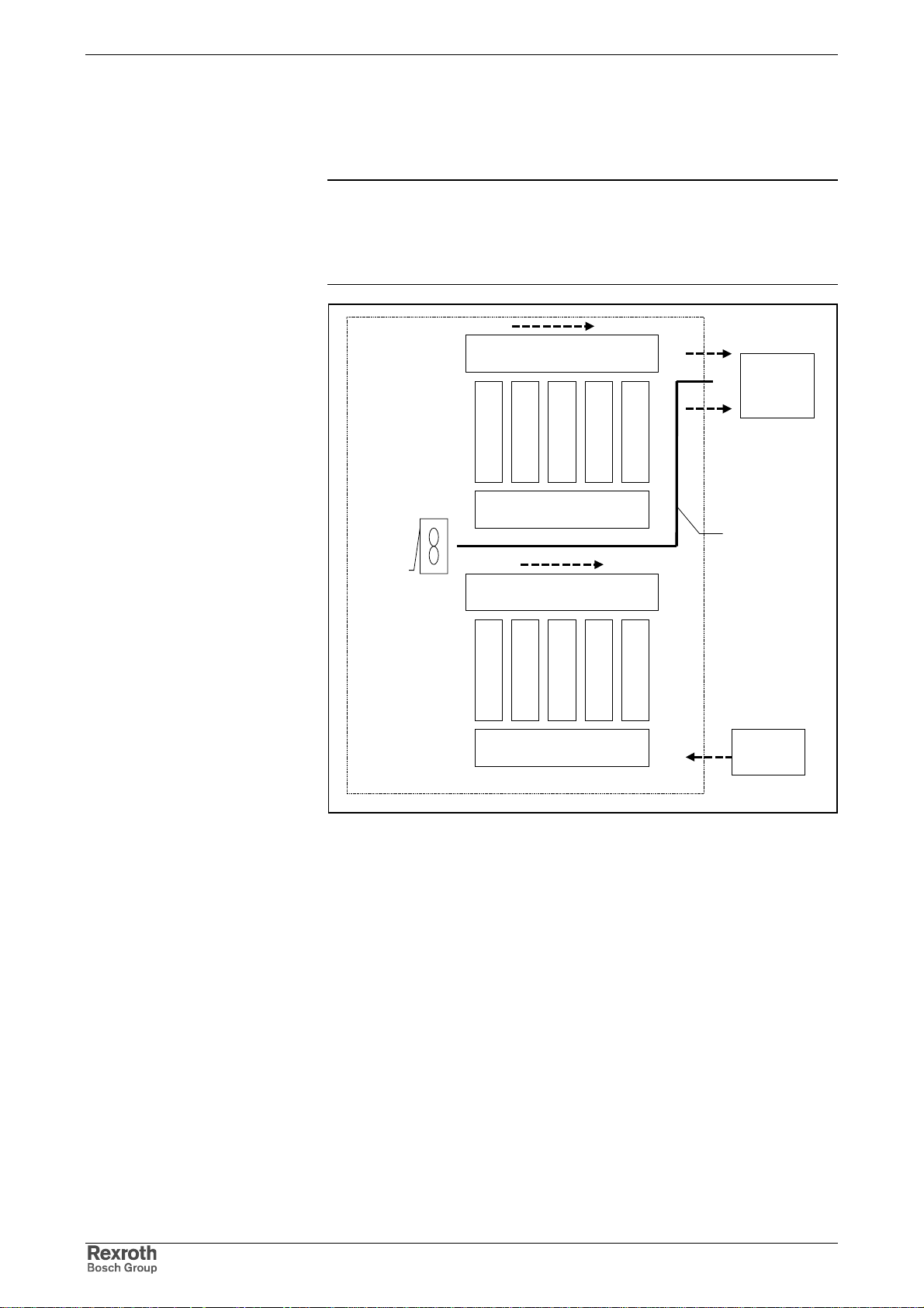
6-24 Mounting and Installation Rexroth IndraDrive
unit
Multiple-Line Arrangement of Drive Controllers
Control Cabinet with Multiple-Line Structure
Note: Particular attention should be paid to the maxim um allowed air
intake temperature of components when they are arranged in
multiple lines in the control cabinet. Where nec essary, cooling
air guides are to be provided with blowers s pecially used for
this purpose.
additional
blower
conveying direction of heated air
in flow-off area
intake area of cooling air for
upper device line
conveying direction of heated air
in flow-off area
intake area of cooling air for
lower device line
outlet air to
cooling unit
air guide
supply air
from cooling
Fig. 6-30: Example of arrangement for multiple-line structure with components
DOK-INDRV*-FU*********-IB01-EN-P
 Loading...