

Bosch IMSA Prototype Classes Scrutineering, DDU 9 System Manual

IMSA Prototype Classes Scrutineering
System
Manual
V1.2.5 1/28/2019

Table of Contents
2 / 47 IMSA Prototype Class Scrutineering Logger Bosch Motorsport
Table of Contents
Manual ................................................................................................................................................................................... 1
Table of Contents ................................................................................................................................................................. 2
1 Scope ................................................................................................................................................................................. 4
2 Contact .............................................................................................................................................................................. 4
2.1 Sales ................................................................................................................................................................................................................. 4
2.1.1 Track Sales ........................................................................................................................................... 4
3 Components ..................................................................................................................................................................... 5
3.1 LMP2 Architecture ...................................................................................................................................................................................... 5
3.2 Electronic Hardware .................................................................................................................................................................................. 5
3.2.1 DDU9 ................................................................................................................................................... 6
3.2.2 PBX90 .................................................................................................................................................. 6
3.2.3 IMU – MM5.10 .................................................................................................................................... 7
3.2.4 LT4 (DPi Only) ...................................................................................................................................... 7
3.2.5 GPS ...................................................................................................................................................... 7
3.2.6 USB Stick ............................................................................................................................................. 8
3.2.7 X2 Transponders ................................................................................................................................. 8
3.2.8 Leaderlight Controller ......................................................................................................................... 9
3.2.9 Pro/Am Light ....................................................................................................................................... 9
3.2.10 Delphi Yellow Light System ........................................................................................................... 9
3.3 Sensors ........................................................................................................................................................................................................ 10
3.3.1 1 Bar Pressure ................................................................................................................................... 11
3.3.2 3.5 Bar Boost Pressure ...................................................................................................................... 11
3.3.3 Pitot Tube .......................................................................................................................................... 12
3.3.4 Laser Ride Height .............................................................................................................................. 12
3.3.5 Temp Sensor ..................................................................................................................................... 12
3.3.6 LSU 4.9 Lambda Sensor ..................................................................................................................... 13
3.3.7 Engine Speed Sensor ......................................................................................................................... 13
3.3.8 Fuel Flow Meter ............................................................................................................................ 1413
3.4 Sensor Declaration Form ................................................................................................................................................................. 1415
3.5 Component Seals ............................................................................................................................................................................... 1415
4 System Architecture ................................................................................................................................................ 1516
4.1 Team CAN ............................................................................................................................................................................................. 1516
4.1.1 Team Connector ................................................................................................................................................................................. 1516
4.1.2 Team CAN 1 .......................................................................................................................................................................................... 1516
4.1.3 Team CAN 2 .......................................................................................................................................................................................... 1617
4.1.4 Driver ID ................................................................................................................................................................................................. 1617
4.2 Power Supply ....................................................................................................................................................................................... 1718
4.3 Harness ................................................................................................................................................................................................... 1819
5 Loom Certification ................................................................................................................................................... 1920

Bosch Motorsport IMSA Prototype Class Scrutineering Logger 3 / 47
6 CAN Specification .................................................................................................................................................... 2021
6.1 Team Transmitted Channels .......................................................................................................................................................... 2021
6.2 Team Received Channels ................................................................................................................................................................. 2122
6.3 Message Bus ......................................................................................................................................................................................... 2223
6.4 DBC file ................................................................................................................................................................................................... 2223
7 Display Pages ............................................................................................................................................................ 2223
7.1 Driver Page............................................................................................................................................................................................ 2223
7.1.1 Standard ................................................................................................................................................................................................. 2223
7.1.2 Alerts ....................................................................................................................................................................................................... 2324
7.2 Mechanic Page .................................................................................................................................................................................... 2526
8 Loom Layout ............................................................................................................................................................. 2627
9 Appendix ................................................................................................................................................................... 2930
a. DDU9 ....................................................................................................................................................................................................... 2930
b. PBX90 ...................................................................................................................................................................................................... 3031
c. IMU ........................................................................................................................................................................................................... 3132
d. LT4 ............................................................................................................................................................................................................ 3233
e. GPS ........................................................................................................................................................................................................... 3334
f. 1 Bar Pressure ...................................................................................................................................................................................... 3536
g. 3.5 Bar Pressure ................................................................................................................................................................................... 3637
h. Pitot Tube .............................................................................................................................................................................................. 3738
i. Temperature ......................................................................................................................................................................................... 3839
j. Lambda ................................................................................................................................................................................................... 3940
10 Vibration Profile 1 .................................................................................................................................................... 4041
11 Order Form ................................................................................................................................................................ 4142
12 Revisions .................................................................................................................................................................... 4546
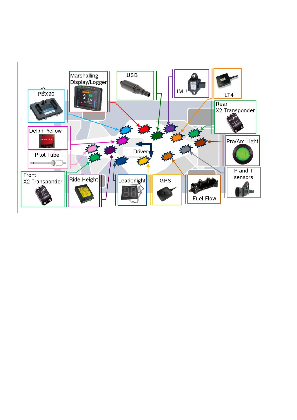
Table of Contents
4 / 47 IMSA Prototype Class Scrutineering Logger Bosch Motorsport
1 Scope
This document contains application notes on the installation and operation of the
IMSA Prototype Classes Scrutineering System.
2 Contact
For technical information please contact:
Erich Ohlde
ERICH.OHLDE@us.bosch.com
Tel: +1-248-221-0418
Or
Aaron Pfeifer
AARON.PFEIFER@us.bosch.com
Tel: +1-248-533-8157
2.1 Sales
Sales will be performed through Bosch Motorsports using the included order form.
2.1.1 Track Sales
Customers requiring spare parts purchased and delivered at the racetrack are
subject to a 10% service fee.

3 | Components
Bosch Motorsport IMSA Prototype Class Scrutineering Logger 5 / 47
3 Components
3.1 LMP2 Architecture
LMP2 classification cars will not utilize the LT4 and LSU 4.9 lambda sensors or any
engine sensor, at this time. The chassis loom of the LMP2 cars must include wiring
for these components. The engine loom is not required to include provisions for
these components in LMP2 cars.
3.2 Electronic Hardware
Component List:
Part Number
Mating Connector
Name
Description
F02U.V0U.290-01
AS616-35 SN
DDU9
P Scrutineering Logger
F02U.V01.794-05
F02U.B00.760-01
F02U.B00.761-01
F02U.003.574-01
PBX90
PowerBox
F02U.V01.511-02
F02U.B00.435-01
IMU
5 axis IMU
1271.032.390
IMU Plate
IMU mounting plate
F01T.A20.070-09
AS114-35PN
LT4
Lambda controller
F02U.V0U.203-01
or
F02U.V0U.268-01
ASU603-03SN
GPS
10 Hz GPS unit
F02U.V0U.267-01
ASL106-05SD
1 Bar Pressure
Air pressure sensor
F02U.V0U.205-01
ASL106-05SB
3.5 Bar Pressure
Boost pressure sensor
F02U.V02.356-01
ASL106-05SN
Temperature Sensor
Air temperature sensor
F02U.V0U.264-01
ASL106-05SE
Pitot Tube
Pitot Tube
F02U.V01.342-01
02W08 F004S BK1 E1AA
USB Stick
Scrutineering data USB
0258.988.001
D261.205.356-01
LSU 4.9
Lambda Sensor
AS108-35SN
Leaderlight panel*
Position display
ASU603-05SN
X2 Transponder*
Timing Transponder
ASL106-05SA-HE
Engine Speed**
RPM sensor
ASDD606-09SD-HE
Fuel Flow*
Fuel flow sensor
ASL606-05SC
Ride Height**
Laser ride height sensor
DTM06-2S-E007
Delphi System*
Yellow light system
DTM06-2S-E007
TV/Video*
Series camera power
DTM06-2S-E007
Pro/Am Light**
Pro/Am indicator
* Denotes component available from IMSA or other spec suppliers
** Denotes component supplied by team

3 | Components
6 / 47 IMSA Prototype Class Scrutineering Logger Bosch Motorsport
3.2.1 DDU9
Functional Description: Logger and Marshalling Display for IMSA Prototype Class
Scrutineering System
Mounting Note:
This device must be fitted in the cockpit in an easily accessible IMSA
approved location.
This device must be mounted away from heat sources. Note maximum
temperature range below.
This device should be mounted so that the display can be easily seen by
the driver while on course.
This device should be mounted to sustain vibrations within the Vibration
Profile 1 defined in the appendix.
Brightness Control: Brightness must be commanded via CAN by a value of 1-6,
message details found in the DBC.
Part Number: F02U.V0U.249-01
Temperature Range: -20 to 70 °C
3.2.2 PBX90
Functional Description: Powerbox for IMSA Prototype Class Scrutineering System
Mounting Note:
This device must be fitted in the cockpit in an easily accessible IMSA
approved location.
This device must be mounted away from heat sources. Note maximum
temperature range below.
This device should be mounted so that the device can be easily accessed.
Part Number: F02U.V01.794-05
Temperature Range: -20 to 85 °C

3 | Components
Bosch Motorsport IMSA Prototype Class Scrutineering Logger 7 / 47
3.2.3 IMU – MM5.10
Functional Description: 5 axis inertial measurement unit
Mounting Note:
This device must be fitted in the cockpit on the centerline of the
longitudinal axis of the vehicle in an easily accessible IMSA approved
location. Use of the mounting bracket listed below is required.
Device to be mounted with connector receptacle facing to the back of the
vehicle and product sticker facing vertically ‘up’. Mounting plate to be
aligned within +/-0.5° of vehicle axes.
Part Number: F02U.V01.511-02
Mounting Bracket Part Number: 1271.032.390
Temperature Range: -20 to 85 °C
3.2.4 LT4 (DPi Only)
Functional Description: 4 channel lambda sensor controller
Mounting Note:
This device must be fitted securely in the cockpit in an easily accessible
location.
This device should be mounted to sustain vibrations within the Vibration
Profile 1 defined in the appendix.
Part Number: F01T.A20.070-09
Temperature Range: -20 to 85 °C
3.2.5 GPS
Functional Description: 10 Hz GPS unit
Mounting Note:
This device must be fitted to the top surface of the vehicle in an IMSA
approved location.
Part Number: F02U.V0U.203-01 OR F02U.V0U.268-01
3 | Components
8 / 47 IMSA Prototype Class Scrutineering Logger Bosch Motorsport
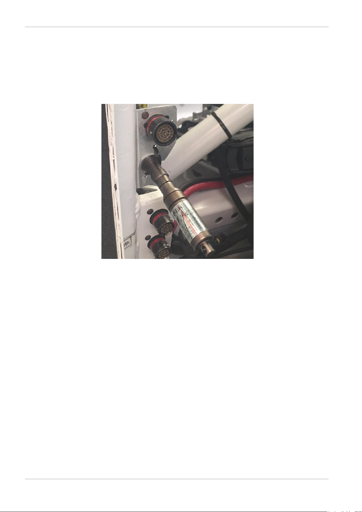
3.2.6 USB Stick
Functional Description: IMSA Scrutineering USB Stick
Mounting Note:
This device must be fitted in a plainly visible IMSA approved location.
Device must be mounted beside the IMSA Diagnostic port on a bulkhead
style plate. An example is shown below.
Temperature Range: -40 to 85 °C
USB Stick Possession: IMSA will distribute and collect USB Sticks at every race,
teams will not receive sticks with scrutineering components nor are they required to
purchase these separately.
3.2.7 X2 Transponders
Functional Description: CAN based transponder for IMSA Prototype Class
Scrutineering System
Mounting Note:
Each car will carry two X2 Transponders.
These devices must be mounted in an IMSA approved location. See IMSA
Bulletins for mounting information.
Temperature Range: 0 to 60 °C

3 | Components
Bosch Motorsport IMSA Prototype Class Scrutineering Logger 9 / 47
3.2.8 Leaderlight Controller
Functional Description: Leaderlight controller boxes and panels
Mounting Note:
This device(s) must be fitted securely.
3.2.9 Pro/Am Light
Functional Description: Pro/Am driver light indicator
Mounting Note:
This device must be mounted away from heat sources.
This device must be mounted in the IMSA specified location specified in
IMSA technical regulations.
Harness Pinout:
Connector DTM06-2S-E007
Pin Description
1 12V PWR
2 GND
3.2.10 Delphi Yellow Light System
Functional Description: Delphi yellow light track condition light system
Mounting Note:
This device must be mounted in a dry location using IMSA supplied Anti-
Vibration Plate in the IMSA specified location.
Antenna must be mounted following IMSA instructions.
3 | Components
10 / 47 IMSA Prototype Class Scrutineering Logger Bosch Motorsport
3.3 Sensors
This section declares sensors that must be directly connected to the IMSA
scrutineering system. IMSA will define required engine sensors and locations for
each engine application. These signals will be fed back to the teams via CAN.
All Prototype cars must run:
Cockpit temperature
Pitot tube
Laser Ride Height sensors (if used)
In addition, DPi cars must run:
Engine Sensors
o Intercooler Upstream temperature(s) (Turbo only)
o Plenum pressure(s) (NA only)
o Plenum temperature(s) (NA only)
o Inlet Port pressure(s) (NA only)
o Boost pressure(s) (Turbo only)
o Inlet Port temperature(s)
o Restrictor Throat pressure(s) (NA only)
o Lambda(s)
o Fuel flow meter
o Engine speed sensor
Sensors must be installed in an IMSA approved location as identified in
Scrutineering System homologation documentation.

3 | Components
Bosch Motorsport IMSA Prototype Class Scrutineering Logger 11 / 47
3.3.1 1 Bar Pressure
Functional Description: Air pressure sensor
Use Case:
Plenum Pressure (NA engines):
Inlet Port (NA engines):
Restrictor Throat Pressure (NA engines):
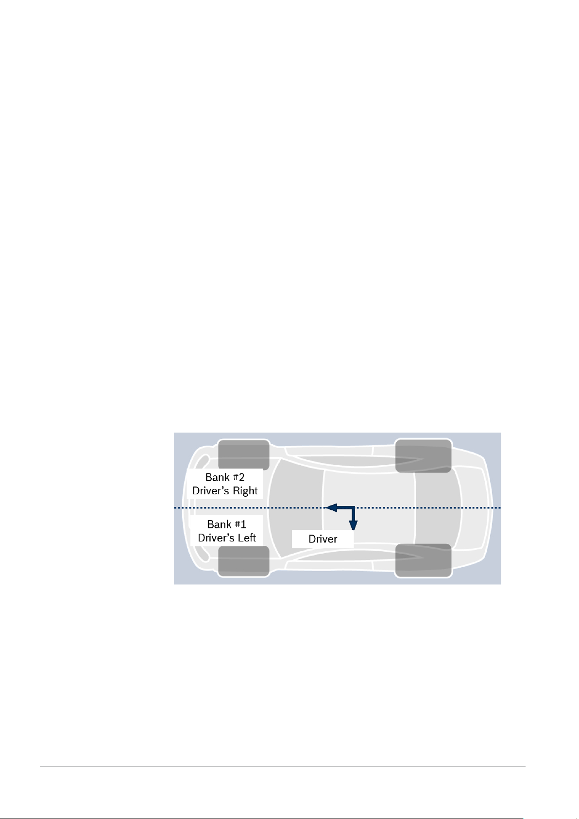
Callout: Driver’s left bank will be Sensor #1
Part Number: F02U.V0U.267-01
Pressure Range: 0.1 – 1.15 bar
Temperature Range: -40 to 125°C
3.3.2 3.5 Bar Boost Pressure
Functional Description: Boost pressure sensor
Use Case:
Boost Pressure (Turbo engines):
Callout: Driver’s left bank will be Sensor #1
Part Number: F02U.V0U.205-01
Pressure Range: 0.5 – 3.5 bar

3 | Components
12 / 47 IMSA Prototype Class Scrutineering Logger Bosch Motorsport
3.3.3 Pitot Tube
Functional Description: Temperature and pressure sensor
Use Case:
Dynamic Conditions:
o Measure dynamic conditions of air flowing over the car.
Mounting Note:
o Pitot sensor must be mounted in the IMSA homologated position.
No other pitot tubes are permitted on the car.
Part Number: F02U.V0U.264-01
3.3.4 Laser Ride Height
Functional Description: Dynamic ride height measurement
Use Case:
Ride Height:
o Measure dynamic ride height of car in multiple locations.
o Each manufacturer may select a sensor to be approved by IMSA.
Mounting Note:
o Ride height sensors must be mounted in the IMSA homologated
position connected to the scrutineering system if run. No other ride
height sensors are permitted on the car.
Harness Pinout:
Connector
ASL606-05SC
Pin
Description
1
12V+ KL.30
2
GND
3
Signal 4 5
3.3.5 Temp Sensor
Functional Description: Temperature sensor
Use Case:
Plenum Temperature (NA engines):
Intercooler Upstream Temperature (Turbo engines):
Inlet Port Temperature:
Cockpit Temperature:
Callout: Driver’s left bank will be Sensor #1
Part Number: F02U.V02.356-01
Temperature Range: -55 to 300 °C
Thread: M6 x 1
Installation Torque: 8 Nm
3 | Components
Bosch Motorsport IMSA Prototype Class Scrutineering Logger 13 / 47
3.3.6 LSU 4.9 Lambda Sensor
Functional Description: Exhaust gas lambda sensor
Use Case:
See Appendix for required sensor mounting information.
One sensor per cylinder bank is required.
Callout: Driver’s left bank will be Sensor #1
Part Number: 0258.988.001
Thread: M18 x 1.5
Installation Torque: 40 to 60 Nm
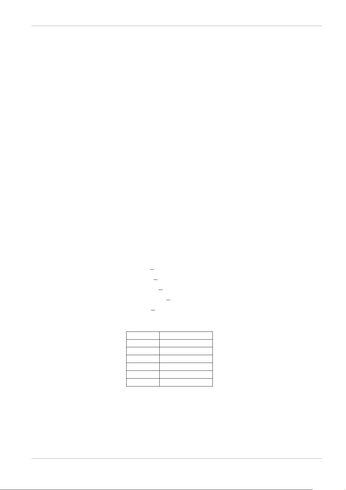
3.3.7 Engine Speed Sensor
Functional Description: Hall effect speed sensor
Use Case:
Each manufacturer may select a sensor to be approved by IMSA.
This sensor must be fitted in an IMSA approved location.
Missing/extra tooth configurations are NOT supported
Recommendation:
Bosch P/N: HA-N F.02U.V0U.714-01
20 tooth symmetrical wheel, no missing teeth
Trigger Wheel Requirements (for HA-N above):
Diameter > 80mm
Slot Width > 10mm
Tooth Width > 5mm
Height of tooth >5mm
Thickness > 8mm
Harness Pinout:
Connector
ASL106-05SA-HE
Pin
Description
1
12V+ KL.30
2
GND
3
Signal 4
5

3 | Components
14 / 47 IMSA Prototype Class Scrutineering Logger Bosch Motorsport
3.3.8 Fuel Flow Meter
Functional Description: CAN based fuel flow meter for IMSA Prototype Class
Scrutineering System
Mounting Note:
This device in an IMSA approved location. See IMSA tech bulletin for
mounting information.
Temperature Range: 0 to 85 °C
3.4 Sensor Declaration Form
Prior to each event weekend, a Sensor Declaration Form must be submitted via
the IMSA TIMS system.
3.5 Component Seals
All Scrutineering system primary components (DDU9, PBX90, and LT4) units must
have an IMSA Scrutineering Seal. Each device ordered through Bosch Motorsport
NA using the attached order form will be delivered with the seal in place. This seal
is not to be removed or transferred.
 Loading...