

Bosch IDH182, GDR18V-1400, GDX18V-1600, IWHT180, HTH181 Operating/safety Instructions Manual
...
1-877-BOSCH99 (1-877-267-2499) www.boschtools.com
Operating/Safety Instructions
Consignes d’utilisation/de sécurité
Instrucciones de funcionamiento y seguridad
IMPORTANT
Read Before Using
●
IMPORTANT
Lire avant usage
●
IMPORTANTE
Leer antes de usar
For English Version
See page 2
●
Version française
Voir page 14
●
Versión en español
Ver la página 27
Call Toll Free for Consumer Information and Service Locations
Pour obtenir des informations et les adresses de nos centres de service après-vente, appelez ce numéro gratuit
Llame gratis para obtener información para el consumidor y ubicaciones de servicio
IDH182
IWBH182
2610051969.qxp_IDH182 IWBH182 1/15/19 10:39 AM Page 1
-2-
▶ Work area safety
Keep work area clean and well lit.
Cluttered or dark areas invite accidents.
Do not operate power tools in explosive
atmospheres, such as in the presence of
flammable liquids, gases or dust. Power
tools create sparks which may ignite the
dust or fumes.
Keep children and bystanders away while
operating a power tool. Distractions can
cause you to lose control.
▶ Electrical safety
Power tool plugs must match the outlet.
Never modify the plug in any way. Do not
use any adapter plugs with earthed
(grounded) power tools. Unmodified
plugs and matching outlets will reduce
risk of electric shock.
Avoid body contact with earthed or
grounded surfaces, such as pipes,
radiators, ranges and refrigerators. There
is an increased risk of electric shock if
your body is earthed or grounded.
Do not expose power tools to rain or wet
conditions. Water entering a power tool
will increase the risk of electric shock.
Do not abuse the cord. Never use the
cord for carrying, pulling or unplugging the
power tool. Keep cord away from heat,
oil, sharp edges or moving parts. Damaged
or entangled cords increase the risk of
electric shock.
When operating a power tool outdoors,
use an extension cord suitable for
outdoor use. Use of a cord suitable for
outdoor use reduces the risk of electric
shock.
If operating a power tool in a damp
location is unavoidable, use a Ground
Fault Circuit Interrupter (GFCI)
protected supply. Use of an GFCI reduces
the risk of electric shock.
▶ Personal safety
Stay alert, watch what you are doing and
use common sense when operating a
power tool. Do not use a power tool
while you are tired or under the influence
Read all safety warnings, instructions, illustrations and specifications
provided with this power tool. Failure to follow all instructions listed
below may result in electric shock, fire and/or serious injury.
SAVE ALL WARNINGS AND INSTRUCTIONS FOR FUTURE REFERENCE
The term “power tool” in the warnings refers to your mains-operated (corded) power
tool or battery-operated (cordless) power tool.
General Power Tool Safety Warnings
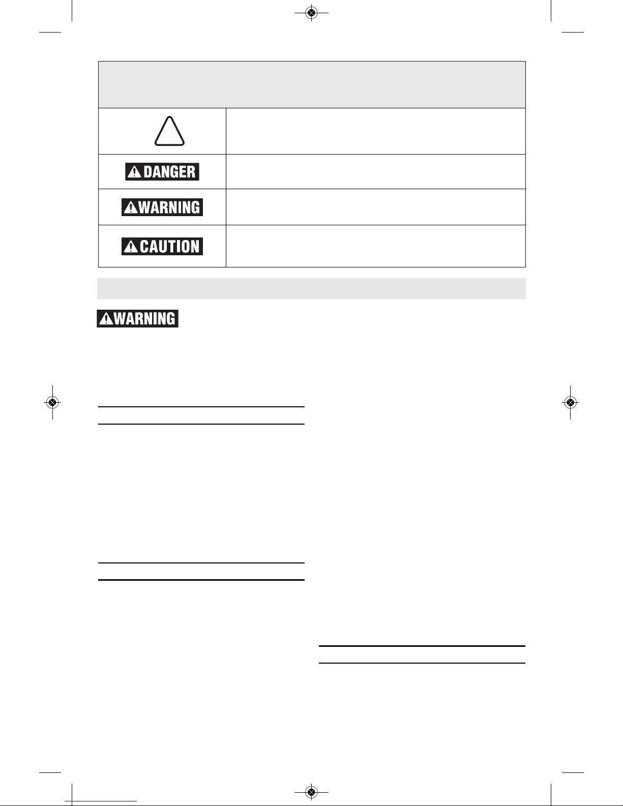
Safety Symbols
The definitions below describe the level of severity for each signal word. Please read the
manual and pay attention to these symbols.
!
This is the safety alert symbol. It is used to alert you to
potential personal injury hazards. Obey all safety messages
that follow this symbol to avoid possible injury or death.
DANGER indicates a hazardous situation which, if not
avoided, will result in death or serious injury.
WARNING indicates a hazardous situation which, if not
avoided, could result in death or serious injury.
CAUTION indicates a hazardous situation which, if not
avoided, could result in minor or moderate injury.
2610051969.qxp_IDH182 IWBH182 1/15/19 10:39 AM Page 2

-3-
General Power Tool Safety Warnings
of drugs, alcohol or medication. A moment
of inattention while operating power tools
may result in serious personal injury.
Use personal protective equipment.
Always wear eye protection. Protective
equipment such as dust mask, non-skid
safety shoes, hard hat, or hearing
protection used for appropriate conditions
will reduce personal injuries.
Prevent unintentional starting. Ensure the
switch is in the off-position before
connecting to power source and / or
battery pack, picking up or carrying the
tool. Carrying power tools with your finger
on the switch or energizing power tools
that have the switch on invites accidents.
Remove any adjusting key or wrench
before turning the power tool on. A
wrench or a key left attached to a rotating
part of the power tool may result in
personal injury.
Do not overreach. Keep proper footing
and balance at all times. This enables
better control of the power tool in
unexpected situations.
Dress properly. Do not wear loose
clothing or jewelry. Keep your hair,
clothing and gloves away from moving
parts. Loose clothes, jewelry or long hair
can be caught in moving parts.
If devices are provided for the
connection of dust extraction and
collection facilities, ensure these are
connected and properly used. Use of dust
collection can reduce dust-related
hazards.
Do not let familiarity gained from
frequent use of tools allow you to
become complacent and ignore tool
safety principles. A careless action can
cause severe injury within a fraction of a
second.
▶ Power tool use and care
Do not force the power tool. Use the
correct power tool for your application.
The correct power tool will do the job
better and safer at the rate for which it
was designed.
Do not use the power tool if the switch
does not turn it on and off. Any power
tool that cannot be controlled with the
switch is dangerous and must be repaired.
Disconnect the plug from the power
source and/or remove the battery pack, if
detachable, from the power tool before
making any adjustments, changing
accessories, or storing power tools. Such
preventive safety measures reduce the risk
of starting the power tool accidentally.
Store idle power tools out of the reach of
children and do not allow persons
unfamiliar with the power tool or these
instructions to operate the power tool.
Power tools are dangerous in the hands of
untrained users.
Maintain power tools and accessories.
Check for misalignment or binding of
moving parts, breakage of parts and any
other condition that may affect the power
tool’s operation. If damaged, have the
power tool repaired before use. Many
accidents are caused by poorly maintained
power tools.
Keep cutting tools sharp and clean.
Properly maintained cutting tools with
sharp cutting edges are less likely to bind
and are easier to control.
Use the power tool, accessories and
tool bits etc. in accordance with these
instructions, taking into account the
working conditions and the work to be
performed. Use of the power tool for
operations different from those intended
could result in a hazardous situation.
Keep handles and grasping surfaces dry,
clean and free from oil and grease.
Slippery handles and grasping surfaces do
not allow for safe handling and control of
the tool in unexpected situations.
▶ Battery tool use and care
Rech ar ge only with the c harger
specified by the manufacturer. A charger
that is suitable for one type of battery
pack may create a risk of fire when used
with another battery pack.
Use power tools only with specifically
designated battery packs. Use of any
other battery packs may create a risk of
injury and fire.
When battery pack is not in use, keep it
2610051969.qxp_IDH182 IWBH182 1/15/19 10:39 AM Page 3
-4-
Hold the power tool by insulated gripping
surfaces, when performing an operation
where the fastener may contact hidden
wiring. Fasteners contacting a “live” wire
may make exposed metal parts of the
power tool “ live” and could give the
operator an electric shock.
Brace the tool properly before use. This
tool produces a high output torque and
without properly bracing the tool during
operation, loss of control may occur
resulting in personal injury.
Use clamps or another practical way to
secure and support the workpiece to a
stable platform. Holding the work by hand or
against your body leaves it unstable and may
lead to loss of control.
Do not drill, fasten or break into existing
walls or other blind areas where electrical
wir i n g m ay exist. If this situatio n i s
unavoidable, disconnect all fuses or circuit
breakers feeding this worksite.
Alwa y s we a r sa f e ty g o gg l es o r ey e
protection when using this tool.
Wear ear protectors when using the tool for
extended periods. Prolonged exposure to
high intensity noise can cause hearing loss.
Use thick cushioned gloves and limit the
exposure time by taking frequent rest
periods. Vibration caused by hammer-drill
action may be harmful to your hands and
arms.
Secure the material being fastened. Never
hold it in your hand or across your legs.
Unstable support can cause loss of control
and injury.
Avoid accidental starting. Be sure the
forw a r d/ r ev er s e sw it c h is in th e off
position before inserting battery pack.
Carrying appliances with your finger on the
switch or inserting the battery pack into an
appl i a nc e with th e switc h on i n vi t es
accidents.
Remove battery pack before changing
accessories. Accidental starting may occur
because battery appliances with a battery
inserted are in the operative condition.
Be prepared for a reaction torque when
“seating” or removing a fastener. The
screwdriver housing may tend to twist in the
oppo s i te dire c ti o n of bi t rota t io n w h en
“seating” or removing a fastener depending
on the torque setting of the tool.
Do no t use du l l or da m a ge d impac t
Safety Rules for Cordless Impact Wrenches
General Power Tool Safety Warnings
away from other metal objects like
paper clips, coins, keys, nails, screws,
or other small metal objects that can
make a connection from one terminal to
another. Shorting the battery terminals
together may cause burns or a fire.
Under abusive conditions, liquid may be
ejected from the battery, avoid contact.
If contact accidentally occurs, flush with
wate r. If liqui d contacts eyes,
additionally seek medical help. Liquid
ejected fro m the ba ttery ma y cause
irritation or burns.
Do not use a battery pack or tool that is
damaged or modified. Damaged or modified
batte rie s ma y exh ib it un pre di cta bl e
behaviour resulting in fire, explosion or risk
of injury.
Do not expose a battery pack or tool to
fire or excessive temperature. Exposure
to fire or temperature above 265 °F may
cause explosion.
Follow all charging instructions and do
not charge the battery pack or tool
outside the temperature range specified
in the instructions. Charging improperly
or at temperatures outside the specified
rang e may da ma ge the battery and
increase the risk of fire.
▶ Service
Have your power tool serviced by a
qualified repair person using only
identical replacement parts. This will
ensure that the safety of the power tool is
maintained.
Never service damaged battery packs.
Service of battery packs should only be
performed by the manufacturer or
authorized service providers.
2610051969.qxp_IDH182 IWBH182 1/15/19 10:39 AM Page 4
-5-
sockets and accessories. When installing
an accessory, insert the impact socket well
onto the output drive. Be sure the output
drive has locked onto the socket correctly.
Do not run the tool while carrying it at
your side. A spinning bit could become
entangled with clothing and injury may result.
Pl a c e the tool onto the fa stener only
when the screwdriver is switched off.
Rota t i ng driver to ol s can sli d e of f the
fastener.
Do no t use this tool as a drill. Too l s
equ i p ped wit h shut-off clutches are not
designed for drilling applications. The output
drive can shut off automatically and without
warning.
B
e careful when driving long screws –
there is a risk of sliding off the fastener
head depending on type of socket or bit
used. First test the run-down of a fastener
and pay attention during the screw driving
process to ensure you do not injure yourself
if the tool bit or socket slid es of f of the
fastener.
Additional Safety Warnings
GFCI and personal protection devices like
electrician’s rubber gloves and footwear will
further enhance your personal safety.
Do not use AC only rated tools with a DC
power supply. While the tool may appear to
work, the electrical components of the AC
rated tool are likely to fail and create a hazard
to the operator.
Keep handles dry, clean and free from oil
and grease. Slippery hands cannot safely
control the power tool.
Develop a periodic maintenance schedule
for your tool. When cleaning a tool be
careful not to disassemble any portion of
th e to ol since interna l wi res may be
misplaced or pinched or safety guard return
sp rings may be improperly moun ted.
Certain cleaning agents such as gasoline,
carbon tetrachloride, ammonia, etc. may
damage plastic parts.
Ensure the switch is in the off position
before inserting battery pack. Inserting the
battery pack into power tools that have the
switch on invites accidents.
Some dust created by
power sanding, sawing,
grinding, drilling, and other construction
activities contains chemicals known to
ca use cance r, bir t h defects or oth e r
reproductive harm. Some examples of
these chemicals are:
• Lead from lead-based paints,
• Crystalline silica from bricks and cement and
other masonry products, and
• Arsenic and chromium from chemically-
treated lumber.
Your risk from th e s e exposures varies,
depending on how often you do this type of
work. To reduce your e xposure to these
chemicals: work in a well ventilated area, and
work with approved safety equipment, such as
those dust masks that are specially designed
to filter out microscopic particles.
Safety Rules for Cordless Impact Wrenches
2610051969.qxp_IDH182 IWBH182 1/15/19 10:39 AM Page 5
-6-
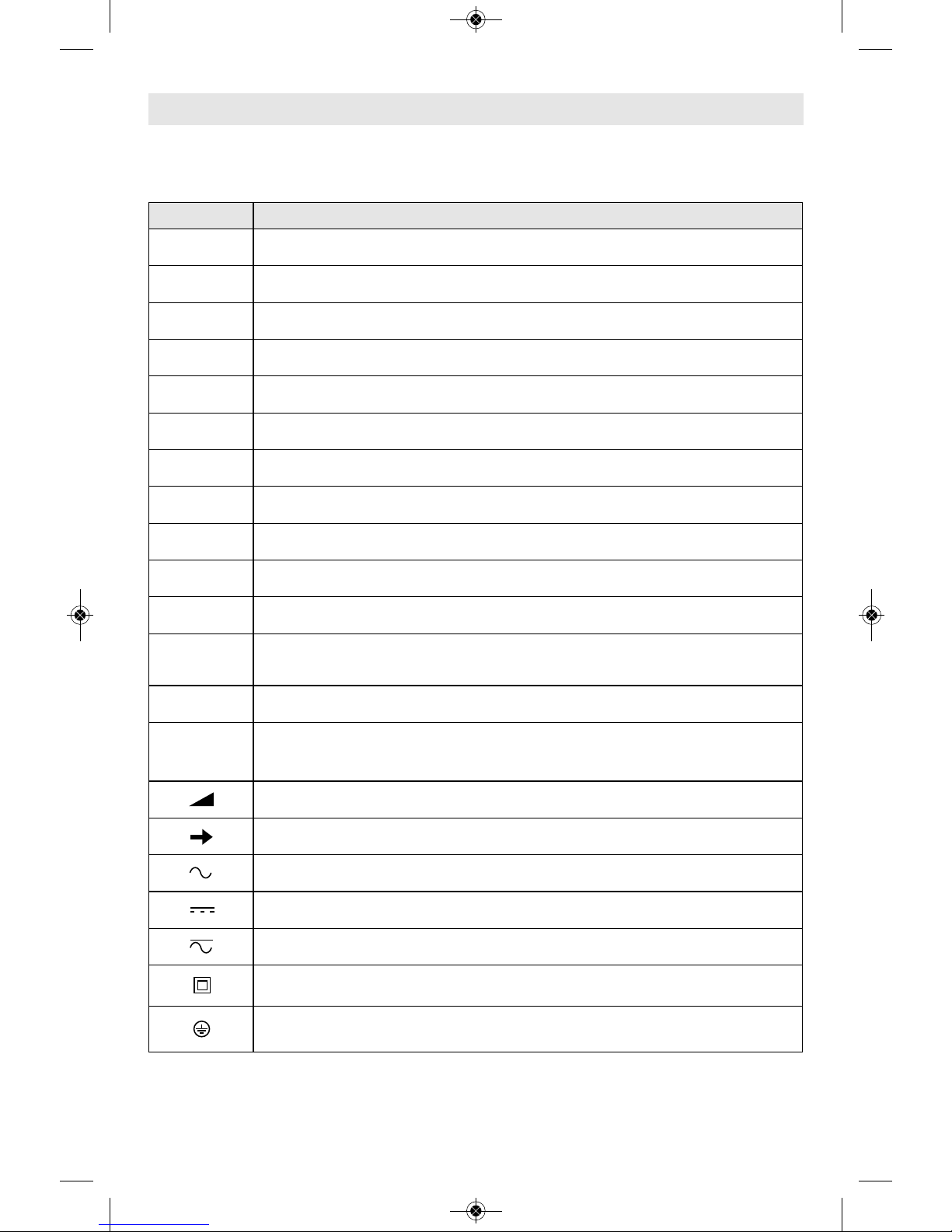
Symbols
Important: Some of the following symbols may be used on your tool. Please study them
and learn their meaning. Proper interpretation of these symbols will allow you to operate
the tool better and safer.
Symbol Designation / Explanation
V Volts (voltage)
Ah Amp hour (measurement of battery capacity)
A Amperes (current)
Hz Hertz (frequency, cycles per second)
W Watt (power)
kg Kilograms (weight)
min Minutes (time)
s Seconds (time)
⌀
Diameter (size of drill bits, grinding wheels, etc.)
n
0
No load speed (rotational speed at no load)
n Rated speed (maximum attainable speed)
.../min
Revolutions or reciprocation per minute (revolutions, strokes, surface
speed, orbits etc. per minute)
0 Off position (zero speed, zero torque...)
1, 2, 3, ...
I, II, III,
Selector settings (speed, torque or position settings. Higher number
means greater speed)
0
Infinitely variable selector with off (speed is increasing from 0 setting)
Arrow (action in the direction of arrow)
Alternating current (type or a characteristic of current)
Direct current (type or a characteristic of current)
Alternating or direct current (type or a characteristic of current)
Class II construction (designates double insulated construction tools)
Earthing terminal (grounding terminal)
2610051969.qxp_IDH182 IWBH182 1/15/19 10:39 AM Page 6
-7-
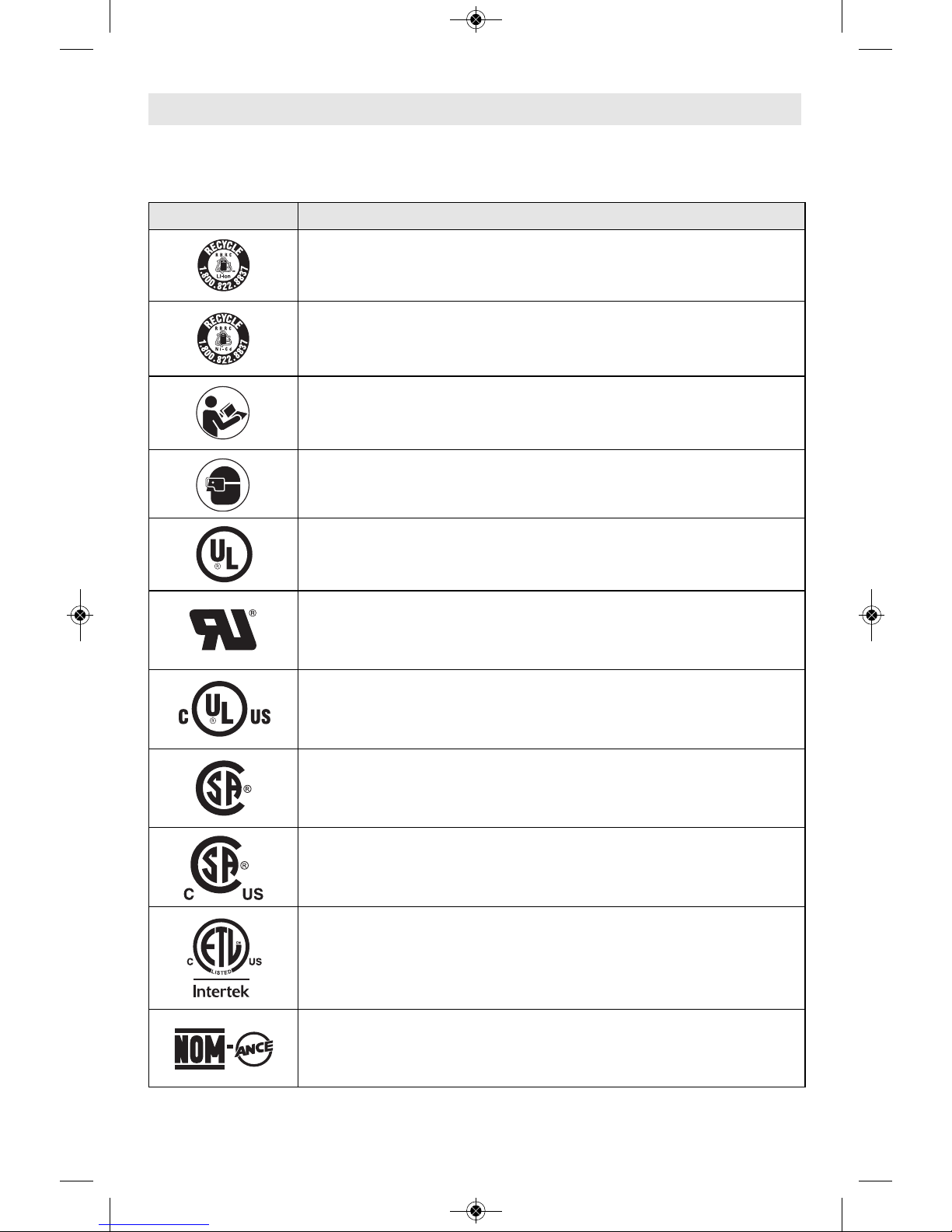
Important: Some of the following symbols may be used on your tool. Please study them
and learn their meaning. Proper interpretation of these symbols will allow you to operate
the tool better and safer.
Symbols
Symbol Designation / Explanation
Designates Li-ion battery recycling program
Designates Ni-Cad battery recycling program
Alerts user to read manual
Alerts user to wear eye protection
This symbol designates that this tool is listed by Underwriters
Laboratories.
This symbol designates that this component is recognized by
Underwriters Laboratories.
This symbol designates that this tool is listed by Underwriters
Laboratories, to United States and Canadian Standards.
This symbol designates that this tool is listed by the Canadian
Standards Association.
This symbol designates that this tool is listed by the Canadian
Standards Association, to United States and Canadian Standards.
This symbol designates that this tool is listed by the Intertek Testing
Services, to United States and Canadian Standards.
This symbol designates that this tool complies to NOM Mexican
Standards.
2610051969.qxp_IDH182 IWBH182 1/15/19 10:39 AM Page 7
-8-
Functional Description and Specifications
Disconnect battery pack from tool before making any assembly,
adjustments or changing accessories. Such preventive safety measures
reduce the risk of starting the tool accidentally.
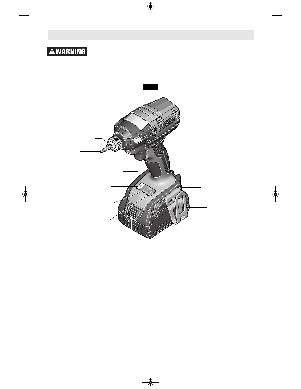
Cordless Impact Drivers IDH182
Model number IDH182
Voltage rating 18 V
No-Load Speed Impact Rate
Setting 1: 0-1300/min 0-1100/min
Setting 2: 0-2000/min 0-2600/min
Setting 3: 0-2800/min 0-3200/min
Maximum torque 1,650 in-lbs
Maximum Capacities
Chuck size 1/4" Hex-shank with power groove
Output drive 1/2" Square drive with Friction Ring
FIG. 1
LOCKING
SLEEVE
VENTILATION
OPENINGS
FORWARD/REVERSING
LEVER & TRIGGER LOCK
VARIABLE SPEED
TRIGGER SWITCH
BATTERY PACK
RELEASE BUTTON
BATTERY PACK
BELT CLIP
(Optional Accessory)
BIT AND BIT
STORAGE AREA
RUBBERIZED GRIP
BUILT IN WORK LIGHT
BIT
WORK LIGHT
ON/OFF BUTTON
VARIABLE SPEED
SELECTOR
VARIABLE SPEED
CONTROL INDICATOR
OUTPUT DRIVE
Battery Packs/Chargers
Please refer to the battery/charger list, included with your tool.
Allowed ambient temperature
– during charging
– during operation/storage
32...113 °F (0...+45 °C)
–4...122 °F (–20...+50 °C)
2610051969.qxp_IDH182 IWBH182 1/15/19 10:39 AM Page 8
-9-
Functional Description and Specifications
Disconnect battery pack from tool before making any assembly,
adjustments or changing accessories. Such preventive safety measures
reduce the risk of starting the tool accidentally.
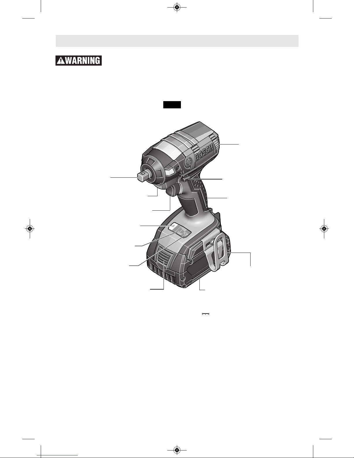
Cordless Impact Wrenches IWBH182
FIG. 1a
VENTILATION
OPENINGS
FORWARD/REVERSING
LEVER & TRIGGER LOCK
VARIABLE SPEED
TRIGGER SWITCH
BELT CLIP
(Optional Accessory)
RUBBERIZED GRIP
BUILT IN WORK LIGHT
OUTPUT DRIVE
Model number IWBH182
Voltage rating 18 V
No-Load Speed Impact Rate
Setting 1: 0-1300/min 0-1100/min
Setting 2: 0-2000/min 0-2600/min
Setting 3: 0-2800/min 0-3200/min
Maximum torque 1,650 in-lbs
Maximum Capacities
Output drive 1/2" Square drive
BATTERY PACK
RELEASE BUTTON
BATTERY PACK
WORK LIGHT
ON/OFF BUTTON
VARIABLE SPEED
SELECTOR
VARIABLE SPEED
CONTROL INDICATOR
Battery Packs/Chargers
Please refer to the battery/charger list, included with your tool.
Allowed ambient temperature
– during charging
– during operation/storage
32...113 °F (0...+45 °C)
–4...122 °F (–20...+50 °C)
2610051969.qxp_IDH182 IWBH182 1/15/19 10:39 AM Page 9
Disconnect battery pack
from tool before making
any assembly, adjustments or changing
accessories. Such pr e ventive safety
measures reduce the risk of starting the tool
accidentally.
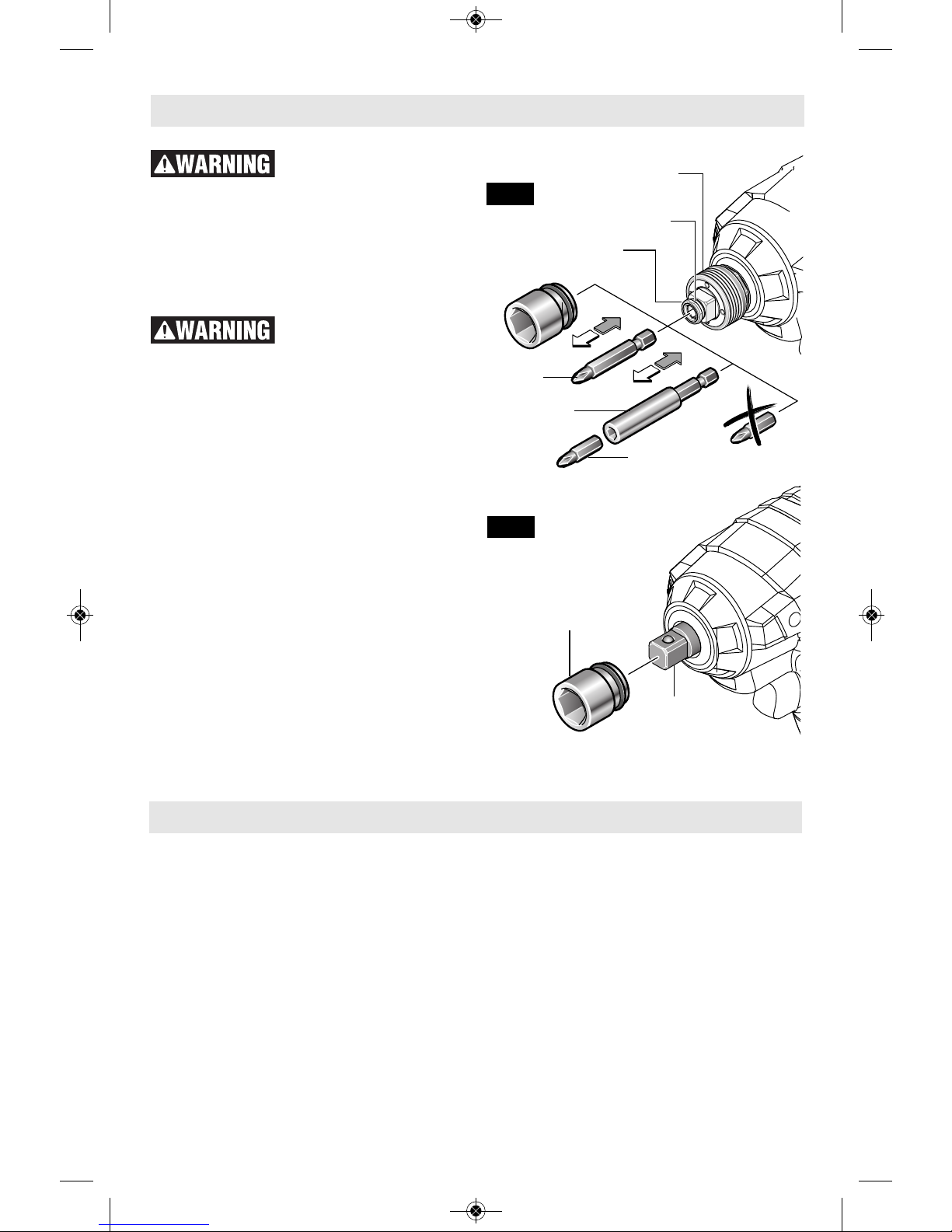
INSERTING AND REMOVING
ACCESSORIES
(Model IDH182 only)
To avoid loss of control,
ensure bit is locked in
chuck by pulling on bit after it has been
inserted. The chuck accepts only standard
1/4" hexagonal shank accessories with
power groove.
Your tool is equipped with a Socket-Ready™
quick release chuck. The Socket-Ready™
chuck includes a 1/4" hex chuck designed for
impact ready bits and accessories and a 1/2"
square drive for use with impact wrench
sockets.
When using the 1/4" hex chuck insert a bit or
accessory by simply pulling the locking sleeve
forward and inserting the desired accessory
into the chuck and release locking sleeve
(Fig. 2). To remove a bit or accessory, pull
locking sleeve forward and simply remove it
from the chuck.
(Model IWBH182 and IDH182 only)
When using the 1/2" square drive, attach only
high quality impact ready accessories with the
proper size square drive designed for use with
impact wrenches. To install a socket, simply
push completely onto output drive.
-10-
Assembly
Operating Instructions
INTENDED USE
This tool is intended for the fastening and
loosening of bolts, nuts and various threaded
fasteners. This tool is not intended for use as a
drill.
VARIABLE SPEED CONTROLLED
TRIGGER SWITCH
Your tool is equipped with a variable speed
trigger switch. The tool can be turned "ON" or
"OFF" by squeezing or releasing the trigger.
The speed can be adjusted from the minimum
to maximum nameplate RPM by the pressure
you apply to the trigger. Apply more pressure
to increase the speed and release pressure to
decrease speed (Fig. 1).
BRAKE
When th e trigge r switch is rele a s ed it
activates the brake to stop the chuck quickly.
This is especially useful in the repetitive
driving and removal of screws.
VARIABLE SPEED CONTROL SELECTOR
The speed of the power tool can be adjusted
by toggling the variable speed control on the
foot of the drill. The speed of the drill is
indicated by the indicator lights at the foot of
OUTPUT
DRIVE
SOCKET
FIG. 3
LOCKING SLEEVE
FIG. 2
SCREWDRIVER
BIT
BIT HOLDER
SCREWDRIVER BIT
CHUCK
FRICTION
RING
2610051969.qxp_IDH182 IWBH182 1/15/19 10:39 AM Page 10
BUILT IN WORK LIGHT
Your tool is also equipped with three work
lights for better visibility when driving. The
lights turn on when the trigger is pulled or when
the l i ght bu t t o n at the foot o f the dri l l is
activated. The light will automatically turn off
within 20 second after releasing the trigger or
may be turned off manually by pressing the
light button at the foot of the drill (Fig. 5).
BIT STORAGE AREA
Your tool is equipped with a bit and storage
area that is conveniently located in the handle
base where it is always handy and unlikely to
get lost or misplaced (Fig. 5).
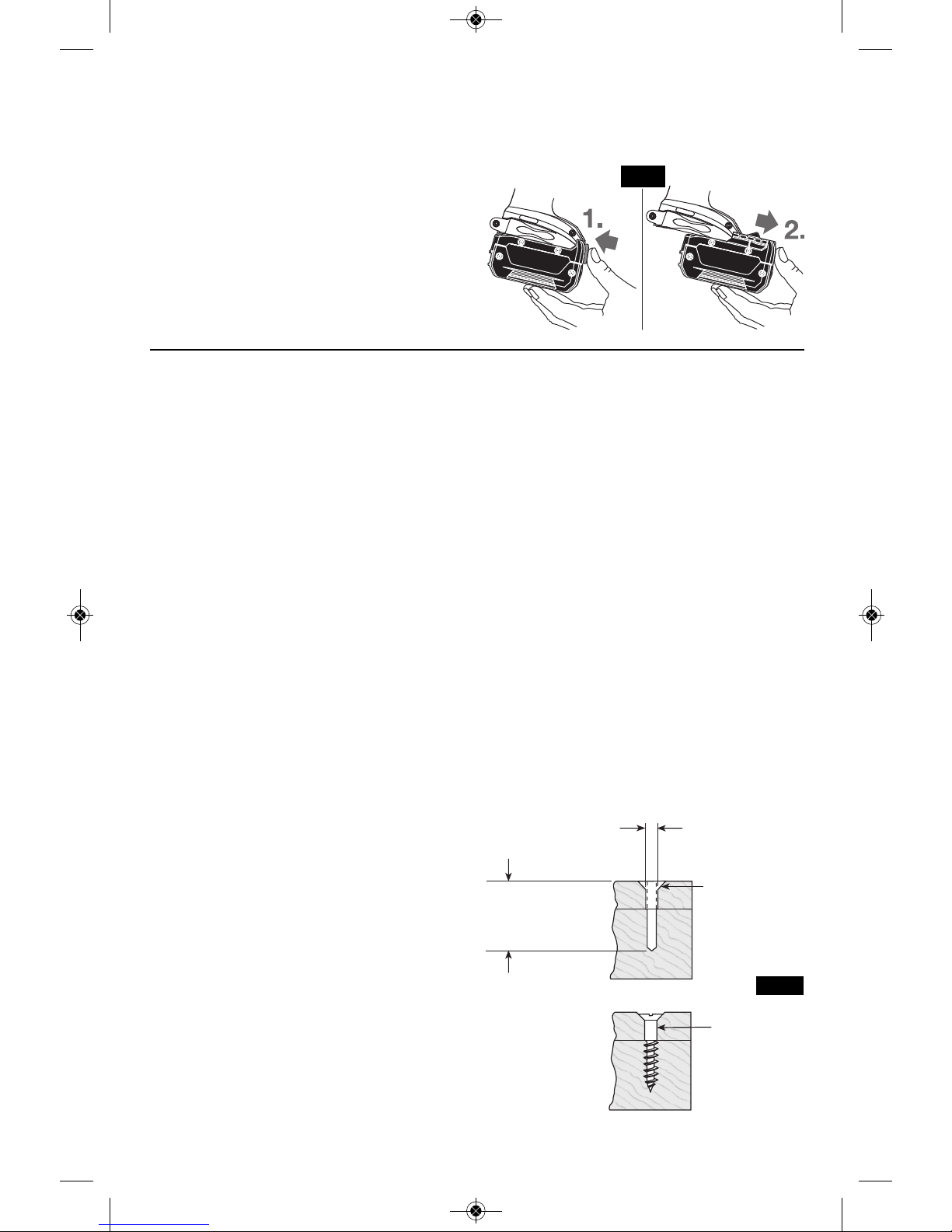
BELT CLIP (Optional Accessory)
When the tool is attached to the belt, position
yourself to avoid entanglement with surrounding
objects. Unexpected entanglement could
cause the tool to fall resulting in injury to the
operator or bystanders.
The optional belt clip accessory will allow you to
conveniently attach your tool to your belt. This
feature will allow you to have both hands free
when climbing a ladder or moving to another
work area.
The belt clip can be attached to either side of
the tool by securing it with a mounting screw.
Always make sure you securely tighten the
mounting screw before use (Fig. 5).
To use clip, turn tool upside down and attach
to your belt.
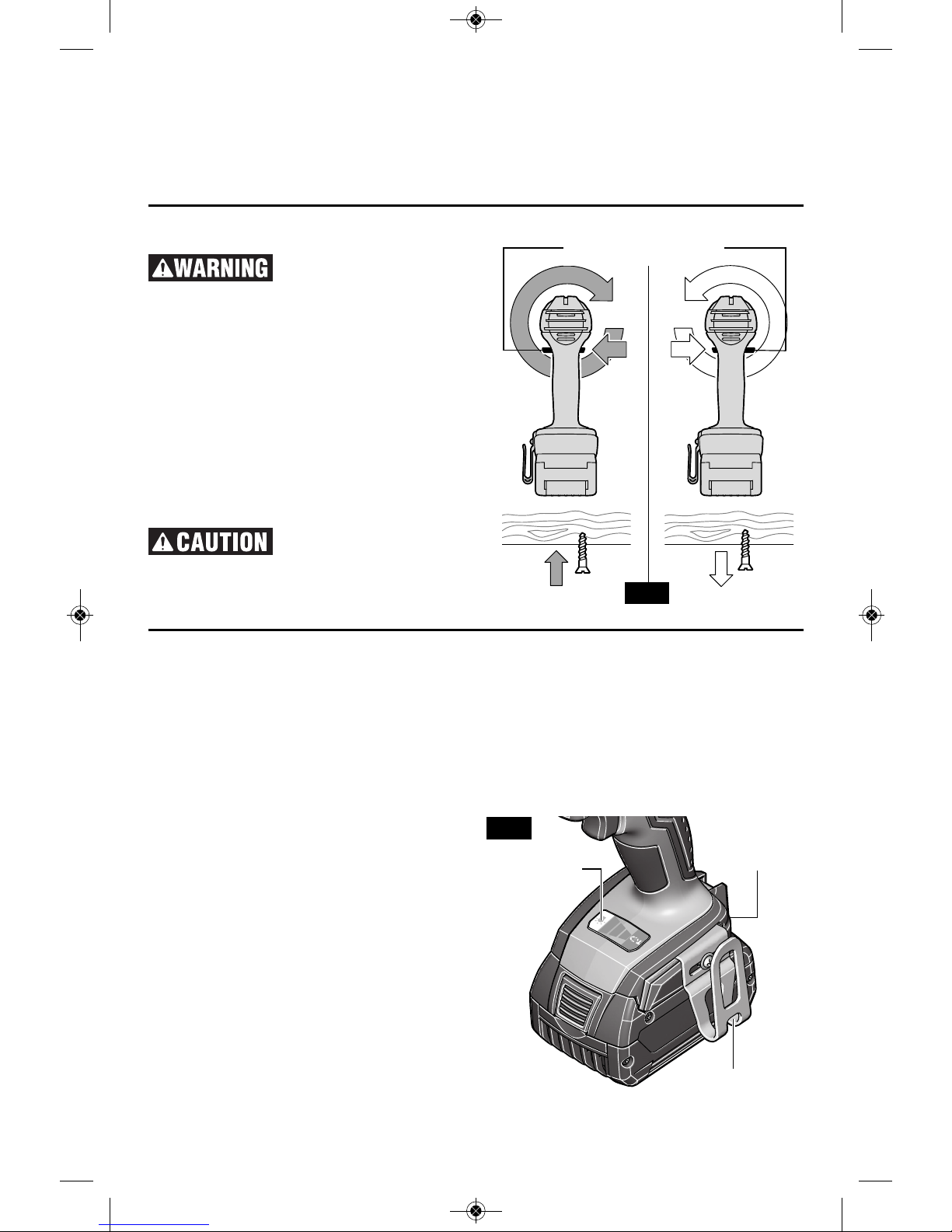
FORWARD/REVERSING
LEVER & TRIGGER LOCK
Af ter tool use, lock
trigger in “OFF” position
to hel p preve nt acci dental starts and
accidental discharge.
Your tool i s equ i p p e d wi t h a fo r w a r d /
reversing lever and trigger lock located above
the trigger (Fig. 4). This lever was designed
for changing rotation of the bit, and for locking
the trigger in an “OFF” position.
For forward rotation, (with chuck pointed
away from you) move the lever to the far left.
For reverse rotation move the lever to the far
right. To activate trigger lock move lever to
the center off position.
Do not change direction
of rotation until the tool
comes to a complete stop. Shifting during
rotation of the chuck can cause damage to
the tool.
-11-
FIG. 5
BELT CLIP
(Optional Accessory)
BIT AND BIT
STORAGE AREA
FIG. 4
FORWARD/REVERSING
LEVER & TRIGGER LOCK
t
he drill located next to the variable speed
control selector button. The lowest speed
setting is indicated by one green LED light
turned and the hightest setting is indicated by
all three grean LED lights turning on (Fig. 1).
N
o -Load Speed impact Rate
Setting 1: 0-1300/min 0-1100/min
Setting 2: 0-2000/min 0-2600/min
Setting 3: 0-2800/min 0-3200/min
WORK LIGHT
ON/OFF BUTTON
2610051969.qxp_IDH182 IWBH182 1/15/19 10:39 AM Page 11
Operating Tips
You will extend the life of your bits and do
neater work if you always put the bit in contact
with the work before pulling the trigger. During
the oper a tion, hold the tool firmly and exert
light, steady pressure. Too much pressure at
low speed will stall the tool. Too little pressure
will keep the bit from cutting and cause excess
friction by sliding over the surface. This can be
damaging to both tool and bit.
DRIVING WITH VARIABLE SPEED
The technique is to start slowly, increasing the
speed as the screw runs down. Set the screw
snug ly by slowing to a stop. Prior to driving
screws, pilot and clearance holes should be
drilled.
Always hold the machine straight on the bolt to
be tightened.
The best method to determine the r i g ht
impacting/tightening duration is by means of a
tri a l . F o r s m all screws, the right
impacting/tightening duration can be reached
in less then 0.5 Sec. Therefore, work with low
RPM and switch the machine off immediately
when the screw is tight and the impacting
sound can be heard.
For screwing larger, longer wood screws into
hard material, pre-drilling is the best method.
TIGHTENING TORQUE
(Models IDH182 & IWBH182 only)
The tightening torque depends on the duration
of the impacting/tightening action. The largest
tightening torque is achieved after approx. 6 to
10 Sec. impacting/tightening action.
The torqu e build - u p dep e n ds on the
following factors:
• Hardness of the bolts/nuts.
• Type of washer (disk washer, spring washer,
seal).
• Hardness of the material to be joined.
• Lubricating effect at the surfaces of the
junction.
This leads to the following application cases:
Hard case: The joining of metal to metal with a
disk washer. The maximum torque is reached
after a relative short impacting/tightening
action.
Medium case: The joining of metal to metal
where spring ring washer, disk spring washer,
stud bolts or bolts/nuts with conical seats are
used.
Soft case: The joining of e.g. metal to wood or
insulation material.
For middle or soft joining cases, the maximum
tightening torque is less as for hard cases.
Therefore, a longer impacting/tightening action
is ne c essary to arrive at the maximum
tightening torque.
FASTENING WITH SCREWS
This procedure shown in (Fig. 7) will enable
you to fasten ma terials together with your tool
without stripping, splitting or separating the
material.
INSERTING AND RELEASING BATTERY
PACK
Set Forward/Reversing lever to the center (off
position). Slide charged battery pack into the
housing until the battery pack locks into
position (Fig. 6).
Your tool is equipped with a secondary locking
lat c h to pre v e nt the ba ttery pack from
completely falling out of the handle, should it
become loose due to vibration.
To remove the battery pack, press the battery
pack release button and slide the battery pack
forward.
Press the battery pack release button again
and slide the battery pack completely out of
tool housing (Fig. 6).
FIG. 6
2. Drill same
diameter as
screw shank.
3. Countersink
same diameter
as screw head.
1. Drill 2/3 diameter and
2/3 of screw length for
soft materials, full
length for hard
materials.
Screw
Apply a slight
even pressure
when driving
screws.
FASTENING
WITH SCREWS
FIG. 7
-12-
2610051969.qxp_IDH182 IWBH182 1/15/19 10:39 AM Page 12
 Loading...