

Bosch ICP-MAP5000-2, ICP-MAP5000-COM, MAP 5000, ICP-MAP5000-S, ICP-MAP5000-SC Installation Manual
MAP 5000
ICP-MAP5000-2 / ICP-MAP5000-COM
en
Installation manual


MAP 5000 Table of contents | en 3
Bosch Sicherheitssysteme GmbH Installation manual 2016.06 | 17 | F.01U.168.332
Table of contents
1
Introduction 5
1.1 Short information 5
1.2 Listings and approvals 5
1.3 Battery handling 5
1.4 Installation considerations 5
1.5 Planning the system 6
1.5.1 Planning the system with IPP-MAP0005 power supply 7
1.5.2 Planning the system with ICP-MAP0012 CAN splitter module 10
1.6 System overview 12
2
Installation 15
2.1 Removing the enclosure knockouts 15
2.2 Installing the tamper switch rail 16
2.3 Mounting the enclosure 17
2.4 Checking the AC connection 19
2.5 Installing the power supply and AC terminal block 19
2.6 Installing the TAE box 22
2.7 Installing the accessory mounting plate 23
2.8 Installing the 12 V converter 25
2.9 Installing the fuse plate (SIV) 26
2.10 Installing the AT 2000 communicator 27
2.11 Installing the hinged mounting plate 32
2.12 Mounting the main panel 35
2.13 Installing the ICP-COM-IF relay module 36
2.14 Installing and connecting the ITS-MAP0008 wireless modem 37
2.15 Antennas 38
3
Connections 40
3.1 Connecting the data bus 40
3.1.1 Internal / external data bus 42
3.1.2 Topology of the external data bus 42
3.1.3 Splitting the external data bus with a CAN splitter module 43
3.2 Connecting the control center 43
3.3 Connecting the main panel 44
3.4 Connecting the power supply 45
3.5 Connecting the LSN gateway 46
3.6 Optional connections 48
3.7 Installing and connecting the tamper switch 50
3.8 Installing the ICP-MAP0060 enclosure lockset 52
3.9 Installing the control center 54
3.10 Connecting the operating and display panel 54
3.10.1 Mounting 54
3.10.2 Connection 55
3.10.3 Programming instructions for ISP-EMIL 120 56
3.11 Final power connections 56
3.12 IP Interface 57
4
Initial set-up and programming 58
4.1 Initial set-up 58
4.2 Programming 58
4.2.1 Help for the programming software 59

4 en | Table of contents MAP 5000
2016.06 | 17 | F.01U.168.332 Installation manual Bosch Sicherheitssysteme GmbH
4.2.2 Standard-compliant programming 59
4.3 Panel software 59
4.3.1 Checking the software version 59
4.3.2 Software updates 60
4.3.3 Manufacturer authorization 60
4.4 Completing the installation 60
4.5 Point types and point evaluation 60
4.6 Output functions 61
4.6.1 Programmable output signals 61
4.6.2 Sirens and communicator in accordance with EN50131 grade 3 63
5
Enclosure options 65
5.1 ICP-MAP0115 power enclosure 65
5.2 Rack mount option for ICP-MAP0120 expansion enclosure 66
6
Maintenance and service 67
6.1 General information 67
6.2 Installer button 67
7
Technical Specifications 69
8
Appendices 72
8.1 Requirements in accordance with VdS class C 72
8.1.1 Selecting the default setting 72
8.1.2 Power supply for areas 72
8.1.3 Control centers and display panel 72
8.1.4 Connection to a management system 72
8.1.5 Printer connection 72
8.1.6 Access levels 72
8.2 Requirements in accordance with EN 50131 grade 3 75
8.2.1 Selecting the default setting 75
8.2.2 Connectable peripherals 75
8.2.3 Arming / disarming without entry / exit delay 75
8.2.4 Arming / disarming with entry / exit delay 75
8.2.5 Arming with automatic bypass 77
8.2.6 Automatic arming / disarming 77
8.2.7 Alarm output via siren and communicator 78
8.2.8 Connection to a management system 78
8.2.9 Printer connection 78
8.2.10 Access levels 78
8.2.11 Additional functions of the main panel 81
8.3 Requirements in accordance with SES 81
8.3.1 Selecting the default setting 81
8.3.2 Automatic arming / disarming 82
8.3.3 Areas with blocking time 82
8.3.4 Access Levels 82
8.3.5 Tamper surveillance of the main panel 85
8.4 Alarm reporting 86
MAP 5000 Introduction | en 5
Bosch Sicherheitssysteme GmbH Installation manual 2016.06 | 17 | F.01U.168.332
1 Introduction
1.1 Short information
This manual describes the installation, wiring, initial set-up and maintenance of the MAP 5000
system.
It is applicable for the following main panels including all accessory MAP 5000 products:
– MAP Main Panel (ICP-MAP5000-2)
– MAP Main Panel with IP Communicator (ICP-MAP5000-COM) including the MAP GSM
module (ITS-MAP0008).
1.2 Listings and approvals
The system is designed to comply with the certifications and approvals listed here.
Region Agency Certification
Germany VdS Class C, VdS G 111040
Europe CE Conformité Européene
Europe EN EN 50131-1:2006 + A1:2009
EN 50131-3:2009
EN 50131-6:2008
EN 50136-2/SP4/DP3
EN 50131-10
Switzerland SES Association of Swiss Installers of Security Systems
Edition V3 / 01.01.2011-d
France AFNOR / CNPP
Cert.
NF&A2P Grade 3
Certificate Number 1133400003A0
According to NF324-H58
1.3 Battery handling
The battery terminals must be covered after installation in order to avoid short circuits.
Suitable terminal covers are included in the scope of delivery of the power supply.
Danger!
Electrictity
Do not short-circuit the battery in the host alarm system. A short-circuited battery can deliver
large currents that might result in serious burns or create a fire hazard.
Further information is available at http://www.boschsecurity.com/standards.
1.4 Installation considerations
– When installing this system, ensure that all local and national wiring codes are met.
– Only authorized service personnel is allowed to install this system.
– Use only the installation material recommended by BOSCH Security Systems to ensure
error-free operation.
– Follow anti-static procedures when handling system components. Ensure that you are
properly grounded to discharge any static charge before you work with system
components.
– Install all components in dry, maintained interior rooms.
– Install the system in a centrally located room that is near the AC Power MAINS.

6 en | Introduction MAP 5000
2016.06 | 17 | F.01U.168.332 Installation manual Bosch Sicherheitssysteme GmbH
– Because the panel is permanently connected equipment, a readily accessible disconnect
device must be included into the building installation wiring.
Danger!
Electric shock
Danger of electric shock if live parts are touched. The alarm system is designed for an ITpower distribution system (230 V). Switch off the power supply of the alarm system before
carrying out maintenance or installation work.
1.5 Planning the system
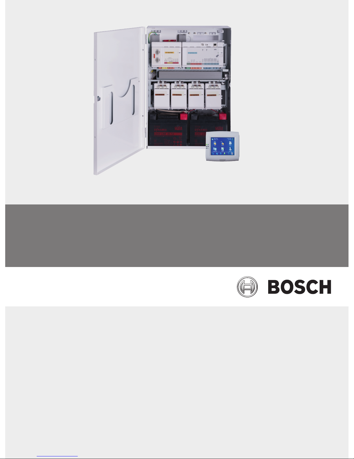
MAP control panel enclosure kit
The ICP-MAP0111 panel enclosure kit is the main system enclosure. This enclosure is designed
to contain the following components:
– ICP-MAP5000 main panel
1
– ICP-MAP0007 DE module
1
– ICP-MAP0010 LSN gateway
1
– ICP-MAP0012 CAN splitter
1
– AT 2000 communicator
2
– IPP-MAP0005 power supply
3
– ICP-MAP0065 AC terminal block
4
– ICP-MAP0050 control panel enclosure tamper switch
– Two batteries (maximum 45 Ah each)
Use the ICP-MAP0120 expansion enclosure kit when the system requirements for power and /
or other remote devices exceed the capacity provided by the ICP-MAP0111 panel enclosure
kit
6.
MAP expansion enclosure kit
The ICP-MAP0120 expansion enclosure kit is designed to contain the following components:
– IPP-MAP0005 power supply
3
– ICP-MAP0010 LSN gateway
5
– ICP-MAP0012 CAN splitter
1
– ICP-MAP0065 AC terminal block
4
– ICP-MAP0055 expansion enclosure tamper switch
– Two batteries (maximum 18 Ah each)
Use the ICP-MAP0115 power enclosure kit when system power requirements exceed the
power capacity of the ICP-MAP0111 panel enclosure kit6.
MAP power enclosure kit
The ICP-MAP0115 power enclosure kit is designed to contain the following components:
– IPP-MAP0005 power supply
3
– ICP-MAP0065 AC terminal block
4
– ICP-MAP0050 control panel enclosure tamper switch
– Four batteries (maximum 40 Ah each)
1
This module mounts on the ICP-MAP0025 hinged mounting plate.
2
This module mounts on the ICP-MAP0020 accessory mounting plate, which mounts to the
back of the enclosure.
MAP 5000 Introduction | en 7
Bosch Sicherheitssysteme GmbH Installation manual 2016.06 | 17 | F.01U.168.332
3
When determining the number of power supplies, it is also necessary to take into account
the inrush current of loads (refer to Planning the system with IPP-MAP0005 power supply, page
7).
4
This assembly is only required if the IPP-MAP0005 power supply is installed.
5
When one or more ICP-MAP0010 LSN gateways are operated remotely, there must be one
IPP-MAP0005 power supply in the same enclosure.
6
Mount the enclosure directly under or at the side (top edge flush) of the control panel
enclosure.
1.5.1 Planning the system with IPP-MAP0005 power supply
Number of power supplies
To guarantee a reliable system booting, take into account the following:
– Inrush current of the connected loads
– Current limit of the IPP-MAP0005 power supply
– Current limit of the ICP-MAP5000 main panel
Notice!
The normal operating condition is not the subject of these considerations.
Load inrush current
– IUI-MAP0001-2 control center: max. 800 mA
– ICP-MAP0010 LSN module: max. 1000 mA, AUX is switched on later
– ICP-MAP0007-2 DE module: negligible
Current limitation
– Power supply per output A / B (short-time): 3.2 A
– Main panel at external BDB: 1.6 A
Refer to Typical configuration with ICP-MAP0111 panel enclosure, page 8.
Definition of power supply segment
A power supply segment is a power supply with all loads supplied by the power supply.
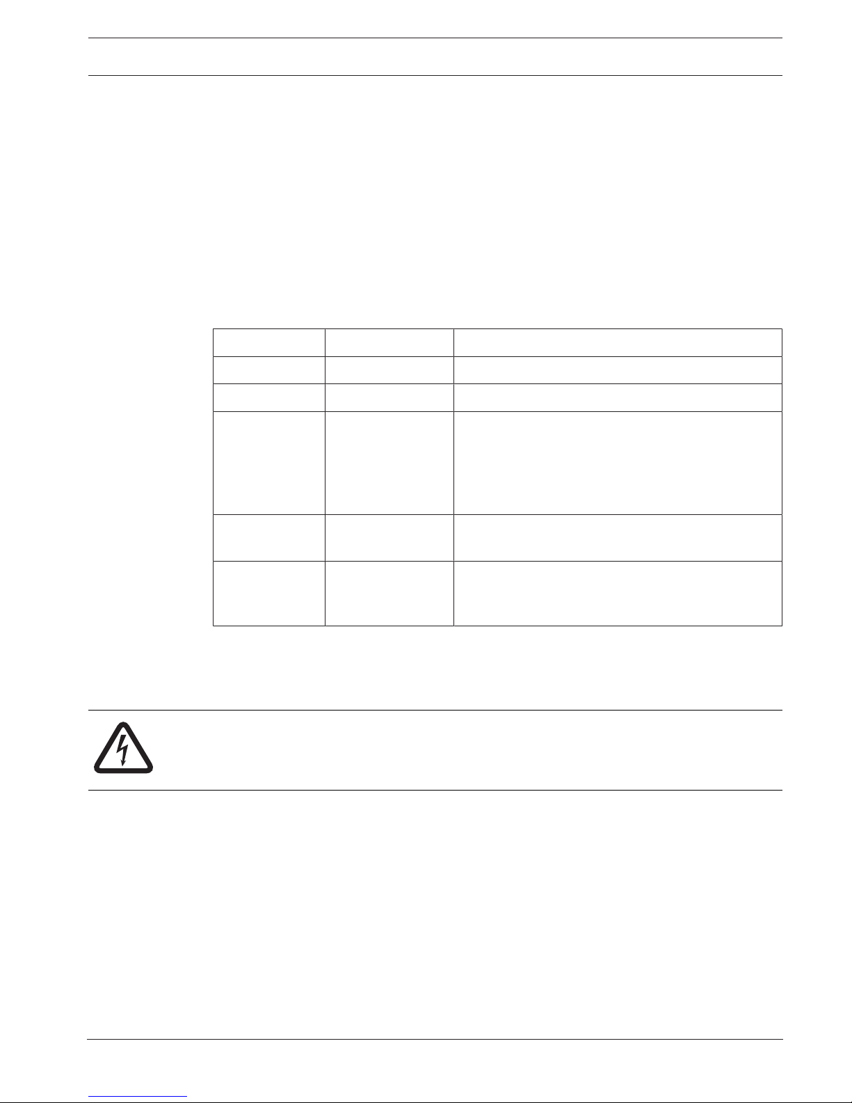
Power supply segment
4-wire cables are used for load connection within the power supply segment.
The following conditions must be taken into account when planning in order to guarantee a
reliable system booting:
Condition 1
3-wire cables are always used for connections between power supply segments (without +28
V, red wire)
8 en | Introduction MAP 5000
2016.06 | 17 | F.01U.168.332 Installation manual Bosch Sicherheitssysteme GmbH
Figure1.1: Wiring of power supply segments
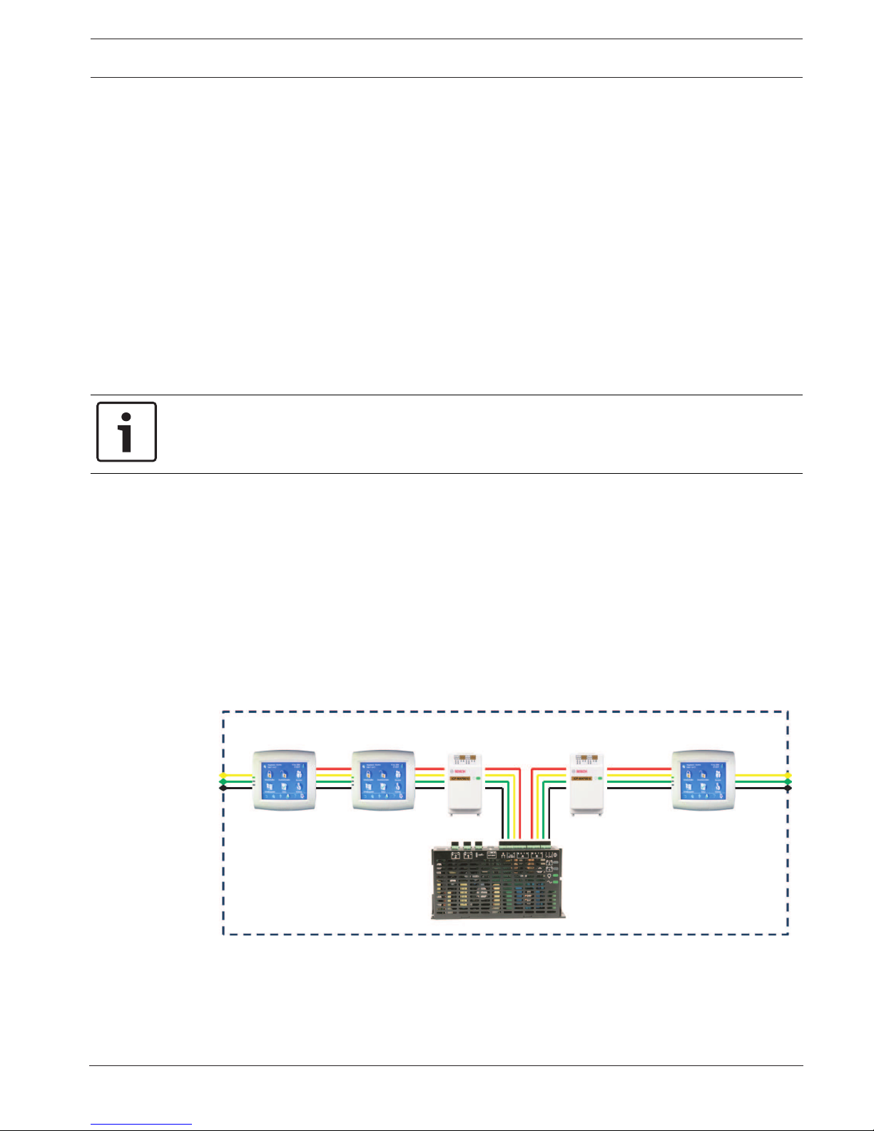
Condition 2
Charged batteries must be connected to the power supply to ensure reliable system start-up.
Figure1.2: Batteries for system booting
Condition 3
To ensure reliable system start-up, it is necessary to take into account the cable length and
wire gauge:
– between power supply and first control center
– between control centers
Refer to , page 10.
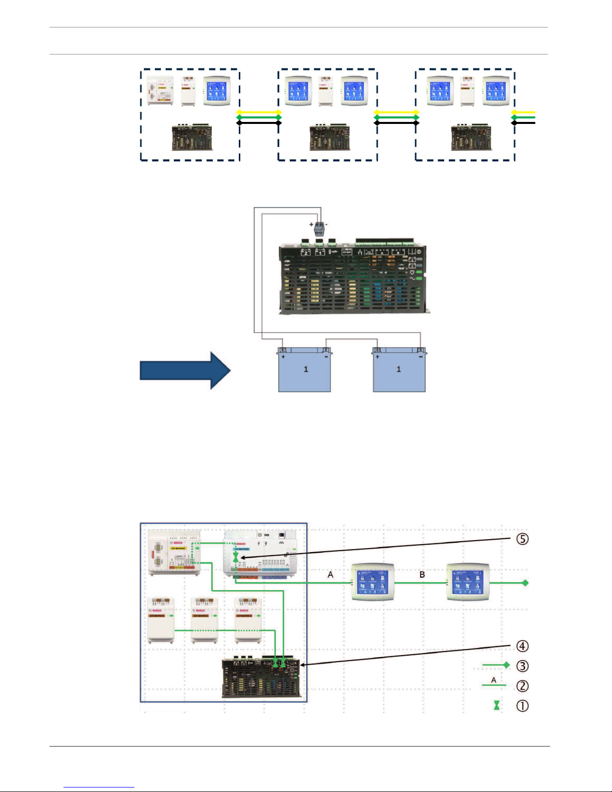
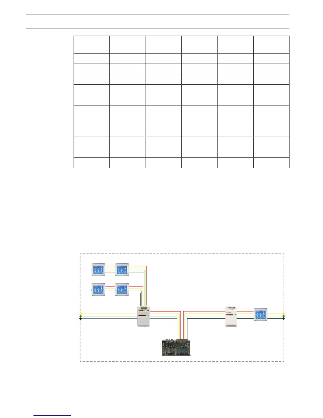
Typical configuration with ICP-MAP0111 panel enclosure
Main panel - DE module - 3 LSN gateway modules - max. 2 control centers
ICP-MAP0111
Figure1.3: Wiring with ICP-MAP0111

MAP 5000 Introduction | en 9
Bosch Sicherheitssysteme GmbH Installation manual 2016.06 | 17 | F.01U.168.332
Key Description
1 Current limitation
2 4-wire connection, take into account cable length
3 3-wire connection to the next power supply segment
4 Short-time current limitation to 3.2 A per output A / B
5 Current limitation to 1.6 A between internal and external BDB
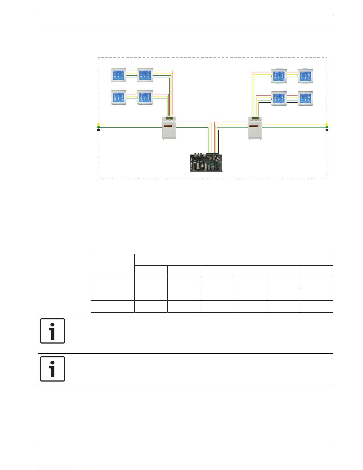
Remote operation with ICP-MAP0120 expansion enclosure
Figure1.4: 2 LSN modules with up to 4 control centers
Figure1.5: Up to 8 control centers
Key Description
1 Current limitation
2 4-wire connection, take into account cable length, refer to , page 10
3 3-wire connection to the next power supply segment
4 Short-time current limitation to 3.2 A per output A / B
Cable length
The maximum number of control centers that can be supplied by one power supply depends
greatly on the length and diameter of the cable used.
10 en | Introduction MAP 5000
2016.06 | 17 | F.01U.168.332 Installation manual Bosch Sicherheitssysteme GmbH
Wire diameter Wire cross-
section
Length A Length B Length C Length D
0.8 mm 0.503 mm2 . 325 m - - - - - - - - -
0.8 mm 0.503 mm2 . 100 m 135 m - - - - - -
0.8 mm 0.503 mm2 . 50 m 225 m - - - - - -
0.8 mm 0.503 mm2 . 50 m 50 m 50 m - - -
1.0 mm 0.785 mm2 . 500 m - - - - - - - - -
1.0 mm 0.785 mm2 . 175 m 175 m - - - - - -
1.0 mm 0.785 mm2 . 100 m 325 m - - - - - -
1.0 mm 0.785 mm2 . 100 m 75 m 75 m - - -
1.0 mm 0.785 mm2 . 50 m 400 m - - - - - -
1.0 mm 0.785 mm2 . 50 m 125 m 125 m - - -
1.0 mm 0.785 mm2 . 50 m 50 m 50 m 50 m
Tab.1.1: Cable lengths
The following applies for VdS
For remote operation of the IPP-MAP0005 power supply, a control center assigned to the
same area must be provided for indication of power supply trouble (trouble in mains supply /
battery).
1.5.2 Planning the system with ICP-MAP0012 CAN splitter module
4 When using a CAN splitter module to split the external BDB into two independent areas,
chose one of the following wiring possibilities:
Wiring with a CAN splitter module and a MAP LSN gateway module
ICP-MAP0012 ICP-MAP0010
MAP 5000 Introduction | en 11
Bosch Sicherheitssysteme GmbH Installation manual 2016.06 | 17 | F.01U.168.332
Wiring with two CAN splitter modules
ICP-MAP0012
ICP-MAP0012
Cable length
The cable length of the splitted external BDB depends on the number of added keypads and of
the cable diameter.
The maximum cable length is 500 m per BDB connector.
4 When planning the system with one or more CAN splitter modules, ensure to use an
appropriate cable length and diameter in accordance with the necessary number of
keypads.
Relation of cable length, diameter and number of keypads
Cable
diameter
Number of keypads
1 2 3 4 5 6
0.6 mm 225 m 225 m 200 m 150 m 120 m 100 m
0.8 mm 400 m 400 m 350 m 275 m 220 m 200 m
1.0 mm 620 m 620 m 550 m 450 m 360 m 300 m
Notice!
These cable lengths apply only for keypads with hardware version 1.0.2. The cable lengths of
older keypads are half of the lengths displayed in the table above.
Notice!
These cable lengths apply for keypads that are mounted with an equal cable distance in
between each other.
See also
– Splitting the external data bus with a CAN splitter module, page 43
12 en | Introduction MAP 5000
2016.06 | 17 | F.01U.168.332 Installation manual Bosch Sicherheitssysteme GmbH
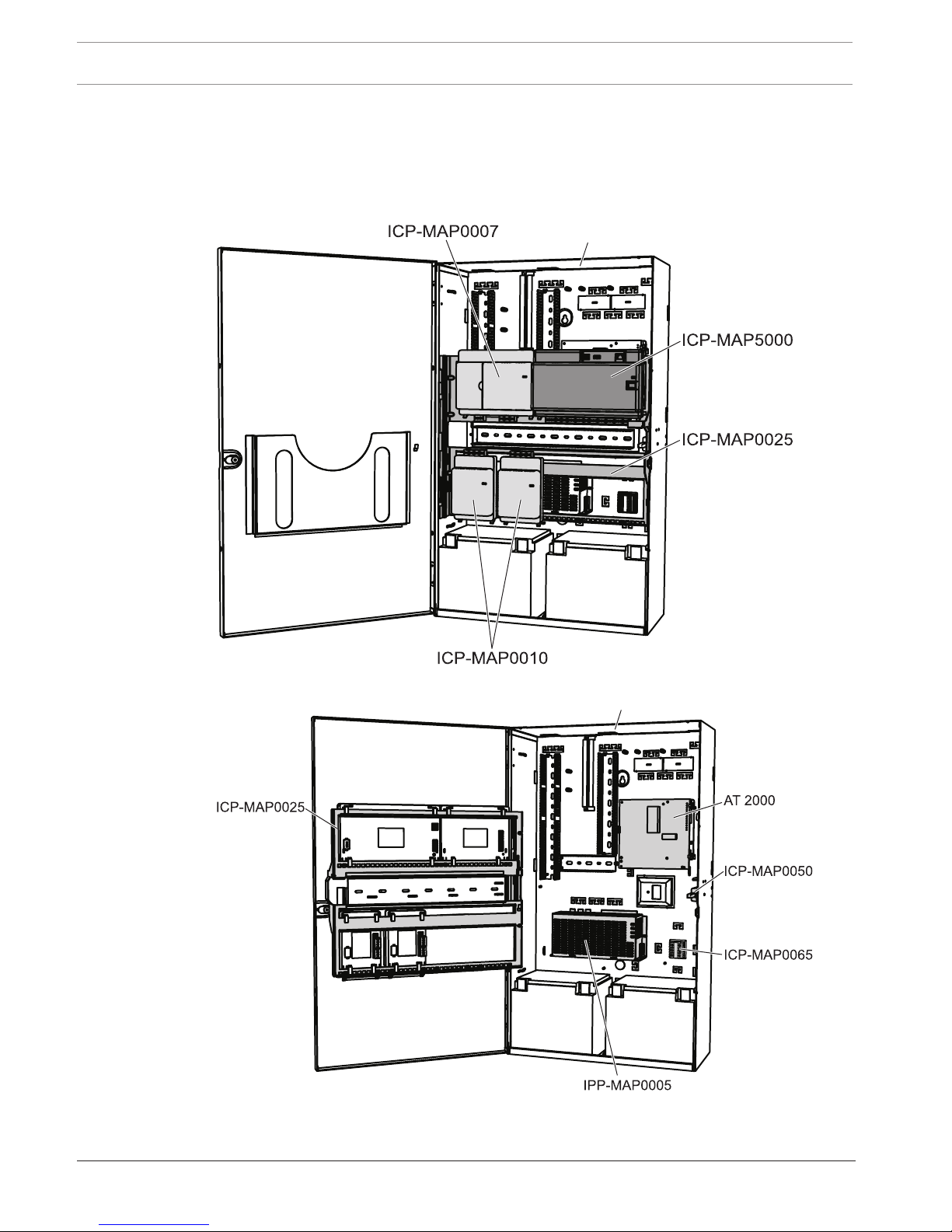
1.6 System overview
This chapter shows an overview of the system as it is installed in the ICP-MAP0111 control
panel enclosure.
System installation in ICP-MAP0111 panel enclosure (hinged mounting plate closed)
ICP-MAP0111
System installation in ICP-MAP0111 panel enclosure (hinged mounting plate open)
ICP-MAP0111
MAP 5000 Introduction | en 13
Bosch Sicherheitssysteme GmbH Installation manual 2016.06 | 17 | F.01U.168.332
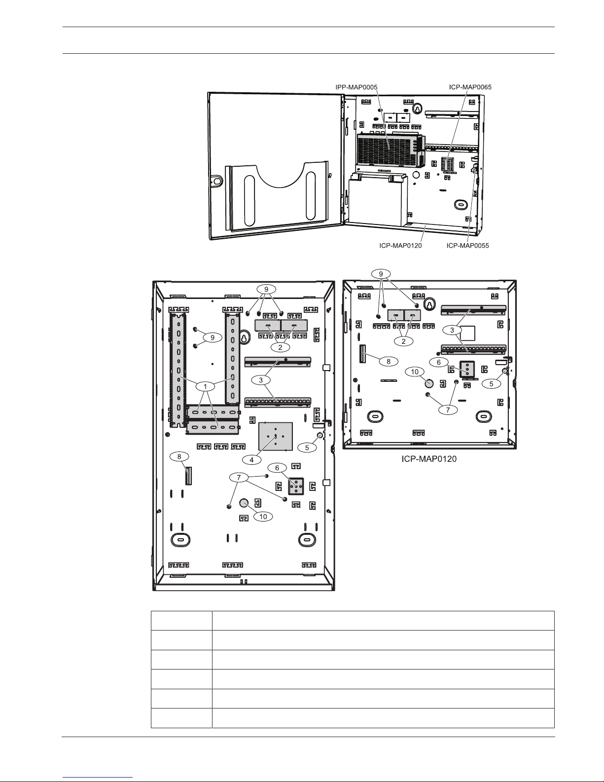
System installation in ICP-MAP0120 expansion enclosure
Enclosure overview
ICP-MAP0111
Element Description
1 Wire trays
2 Wire knockouts
3 Mounting rails for ICP-MAP0020 accessory mounting plate
4 Mounting location for TAE box
5 Knockout for wall tamper

14 en | Introduction MAP 5000
2016.06 | 17 | F.01U.168.332 Installation manual Bosch Sicherheitssysteme GmbH
6 Mounting location for ICP-MAP0065 AC terminal block
7 Earth ground connection points
8 Flange for IPP-MAP0005 power supply
9 Shielding connection points
10 Knockout for AC wires (use when AC wires come in from the back of the
enclosure)
MAP 5000 Installation | en 15
Bosch Sicherheitssysteme GmbH Installation manual 2016.06 | 17 | F.01U.168.332
2 Installation
– Use proper anchor and screw sets when installing the enclosure on surfaces. Refer to the
drill template for detailed instructions.
– Ensure that there is enough free space to the left of the enclosure so that the enclosure
door and the ICP-MAP0025 hinged mounting plate have full range of motion. 460 mm (18
in) for a fully opened door or 32 mm (1.25 in) for 90° opened door is required.
– Ensure that there is at least 100 mm (4 in) of space around the enclosure to allow easy
access to cable conduits.
– Leave adequate space below or next to the enclosure for an ICP-MAP0120 expansion
enclosure for future additions to the system.
– To minimize battery depletion, install the enclosure in locations at normal room
temperature.
– Use the ICP-MAP0111 installation mounting template (F.01U.076.204) or the ICP-
MAP0120 installation mounting template (F.01U.076.205)
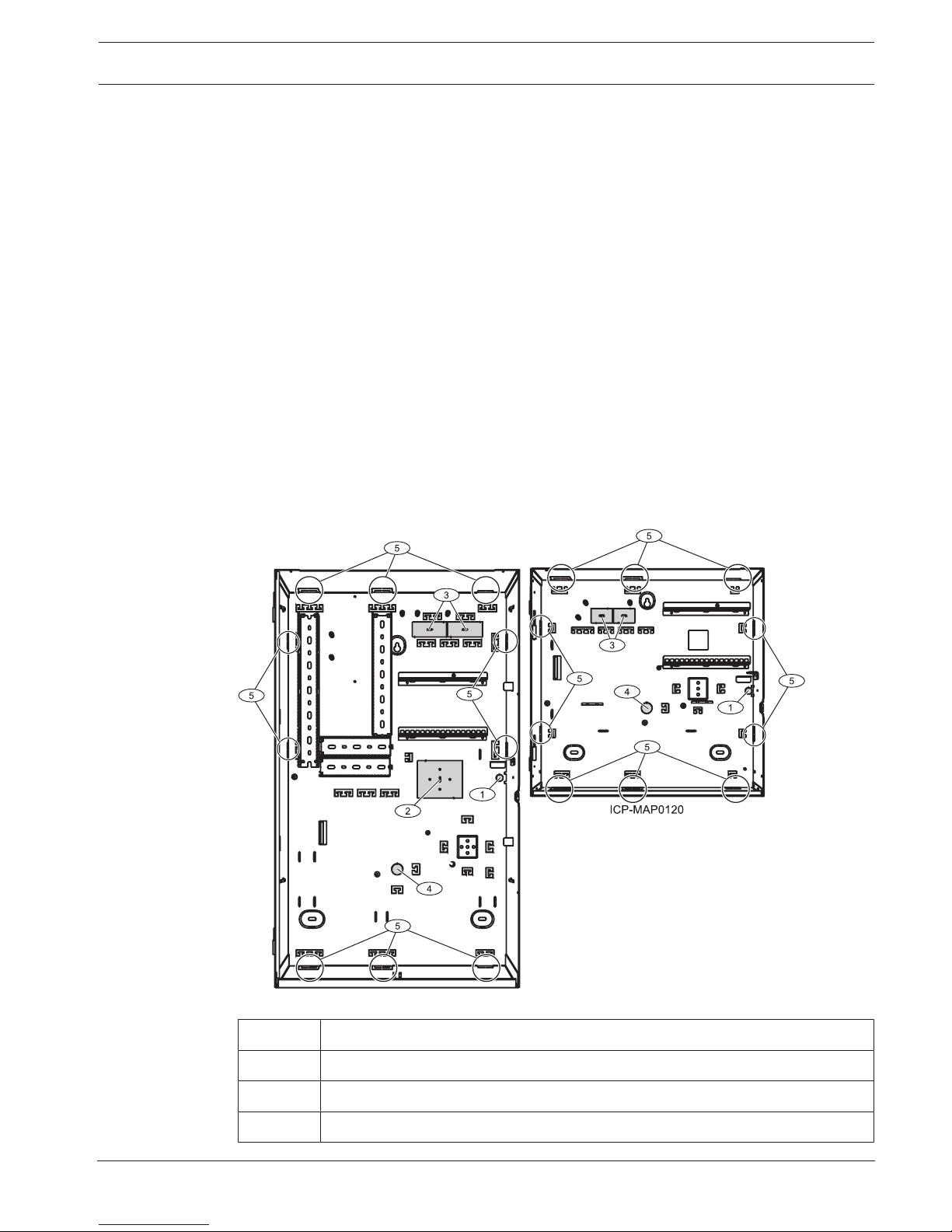
2.1 Removing the enclosure knockouts
1. Unhinge and remove the enclosure door and set it aside.
2. Remove the enclosure knockouts in the order shown in the figure below.
Enclosure knockouts
ICP-MAP0111
Element Description
1 Knockout for wall tamper (required in accordance with EN50131 grade 3)
2 Knockout for TAE box
3 Knockouts for wiring
16 en | Installation MAP 5000
2016.06 | 17 | F.01U.168.332 Installation manual Bosch Sicherheitssysteme GmbH
4 Knockout for AC wires (use when AC wires come in from the back of the
enclosure)
5 Side wall knockouts for wiring
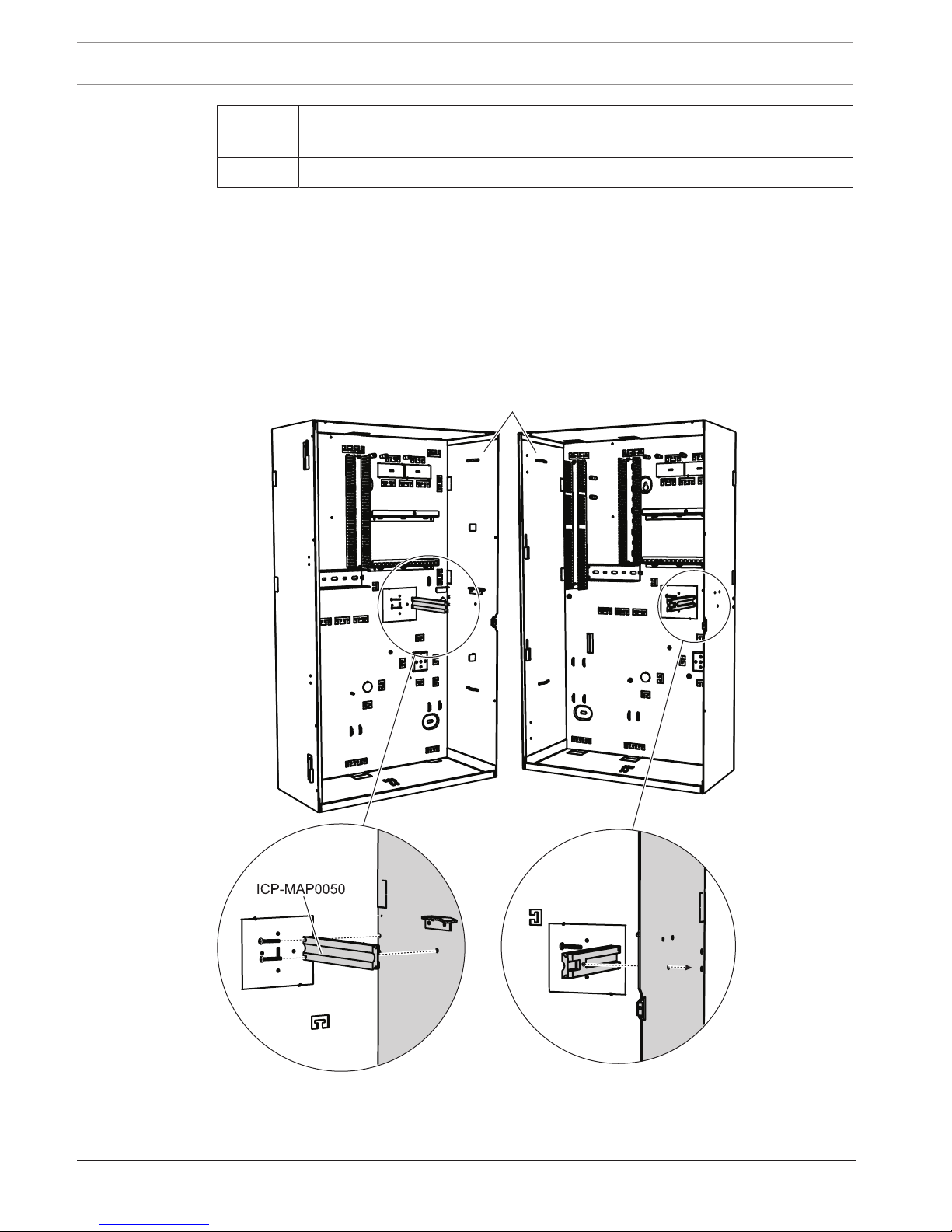
2.2 Installing the tamper switch rail
1. Remove the tamper switch rail from the package.
2. Mount the tamper switch rail to the inner right side of the enclosure as shown in the
figure below.
3. Secure the tamper switch rail with the two supplied screws.
Do not mount the tamper switch at this time.
Mounting the tamper switch rail
ICP-MAP0111
MAP 5000 Installation | en 17
Bosch Sicherheitssysteme GmbH Installation manual 2016.06 | 17 | F.01U.168.332
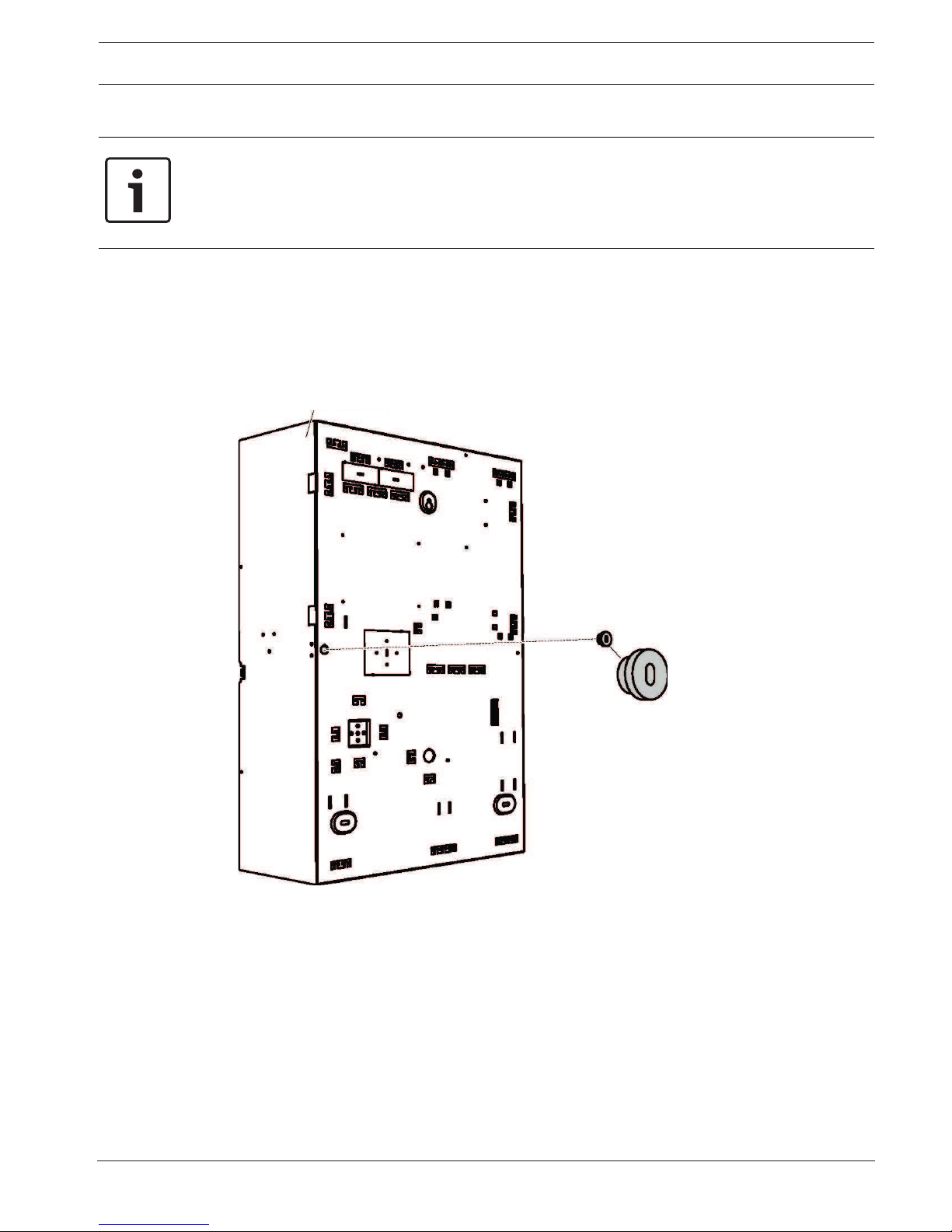
2.3 Mounting the enclosure
Notice!
Ensure that there is enough free space to the left of the enclosure so that the enclosure door
and the ICP-MAP0025 hinged mounting plate have full range of motion.
- For a fully opened door, at least 460 mm (18 in) is required.
- For a door opened at 90°, at least 32 mm (1.25 in) is required.
1. Use the supplied drill template to mark the holes on the intended surface.
The drill template can be found in the enclosure box.
2. If a wall tamper is required, insert the plug for the tamper switch into the back of the
enclosure (required in accordance with EN50131 grade 3) as shown in the figure below.
3. Secure the plug to the wall using a suitable screw (not supplied).
Inserting the wall tamper plug
ICP-MAP0111
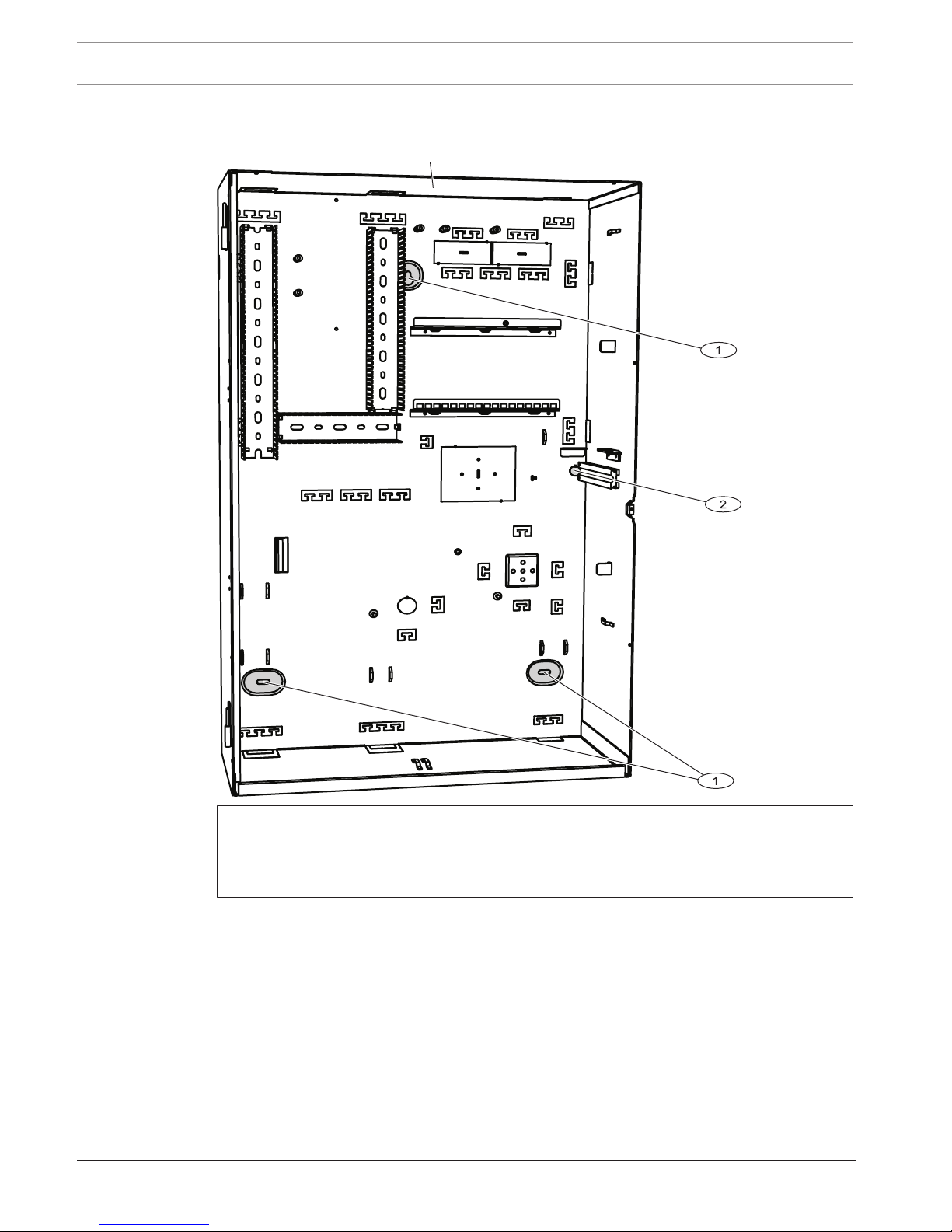
1. Mount the enclosure to the intended surface using suitable screws and anchors (not
supplied). Use the mounting holes as shown in the figure below.
2. Ensure that all screws are tight and that the enclosure is securely fastened to the
mounting surface.
18 en | Installation MAP 5000
2016.06 | 17 | F.01U.168.332 Installation manual Bosch Sicherheitssysteme GmbH
Mounting the enclosure
ICP-MAP0111
Element Description
1 Mounting hole
2 Hole for screw to secure wall tamper plug
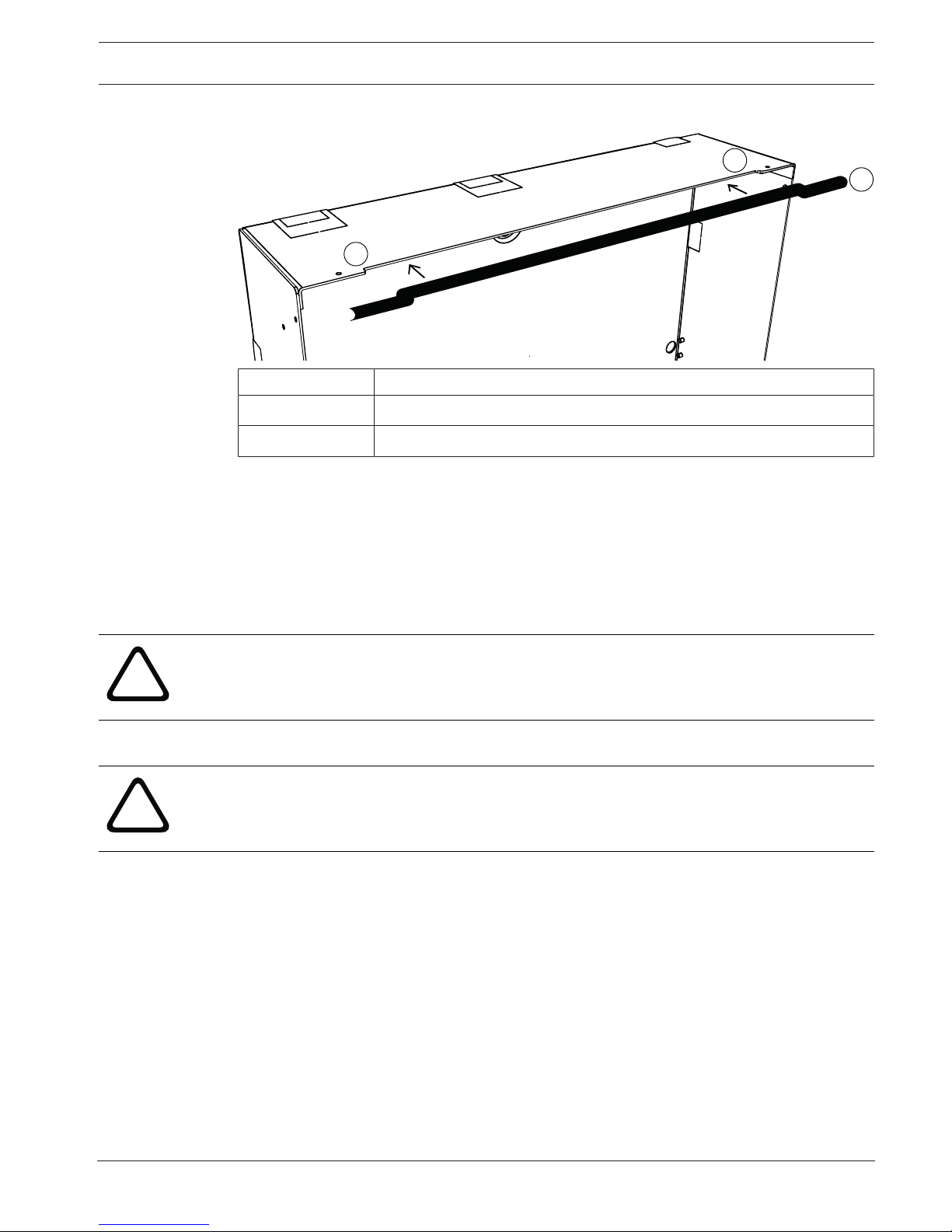
Mounting an edge protection profile (optional)
For an installation according to the regulations of NFa2p AFNOR certification, it is necessary
to mount an edge protection profile on the upper edge of the MAP enclosure.
The edge protection profile can be ordered at http://eshop.wuerth.de/en/US/EUR/ with the
article number 09610027.
1. Mount the edge protection profile on the upper edge of the MAP enclosure from the left
to the right. Ensure not to leave gaps at the cut-outs.
2. Cut off the overlaying edge protection profile on the right side of the enclosure.
MAP 5000 Installation | en 19
Bosch Sicherheitssysteme GmbH Installation manual 2016.06 | 17 | F.01U.168.332
Mounting an edge protection profile
1
1
2
Element Description
1 cut-outs
2 edge protection profile
2.4 Checking the AC connection
1. Ensure that the AC circuit breaker switch is off.
2. Connect the AC line to the AC terminal block.
3. Switch the AC breaker on.
4. Verify that the circuit breaker does not trip and that appropriate line voltage is present on
the fused side of the AC terminal block.
5. Switch the AC breaker off and continue with the rest of the installation.
!
Warning!
After ensuring the AC connection is functional, turn the AC breaker off before continuing the
installation process.
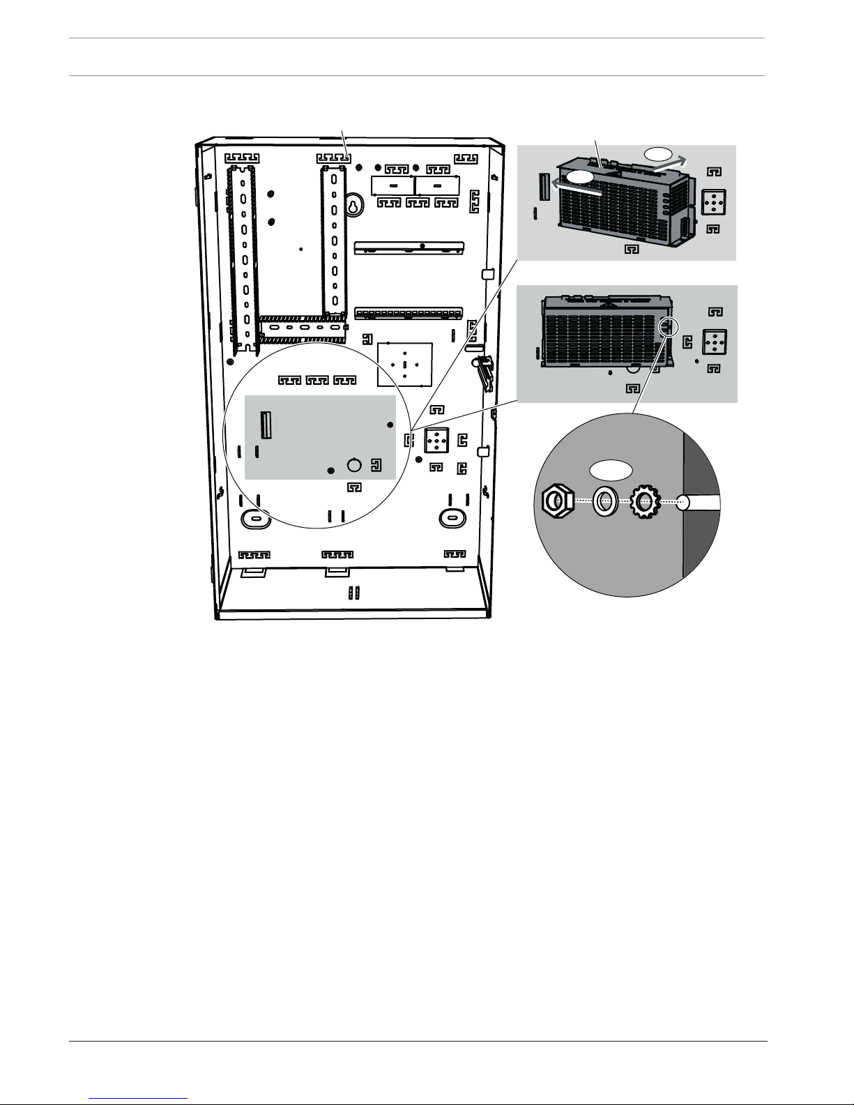
2.5 Installing the power supply and AC terminal block
!
Caution!
Debris
Damage to the power supply due to debris during the installation is possible.
– To prevent damage to the power supply during installation, ensure that the supplied
protective dust cover label is on top of the power supply before installing it.
1. Slide the left side of the power supply against the flange on the left side of the enclosure
back wall.
2. Align the cut-out on the right side of the power supply.
3. Secure the power supply to the enclosure back wall with the supplied hardware in the
following order: external tooth washer, washer, hex nut
20 en | Installation MAP 5000
2016.06 | 17 | F.01U.168.332 Installation manual Bosch Sicherheitssysteme GmbH
Installing the power supply
1
2
IPP-MAP0005
ICP-MAP0111
3
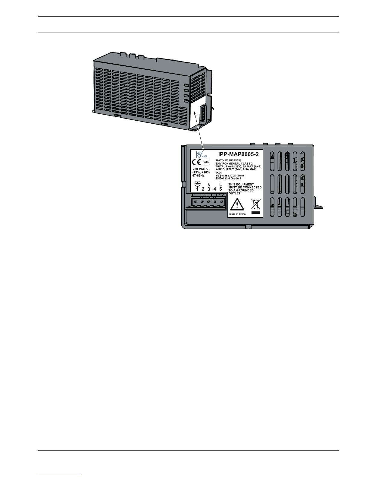
Refer to IPP-MAP0005 power supply ratings label, page 21 for the location of the power supply
ratings label. Refer to Technical Specifications, page 69 for power specifications.
MAP 5000 Installation | en 21
Bosch Sicherheitssysteme GmbH Installation manual 2016.06 | 17 | F.01U.168.332
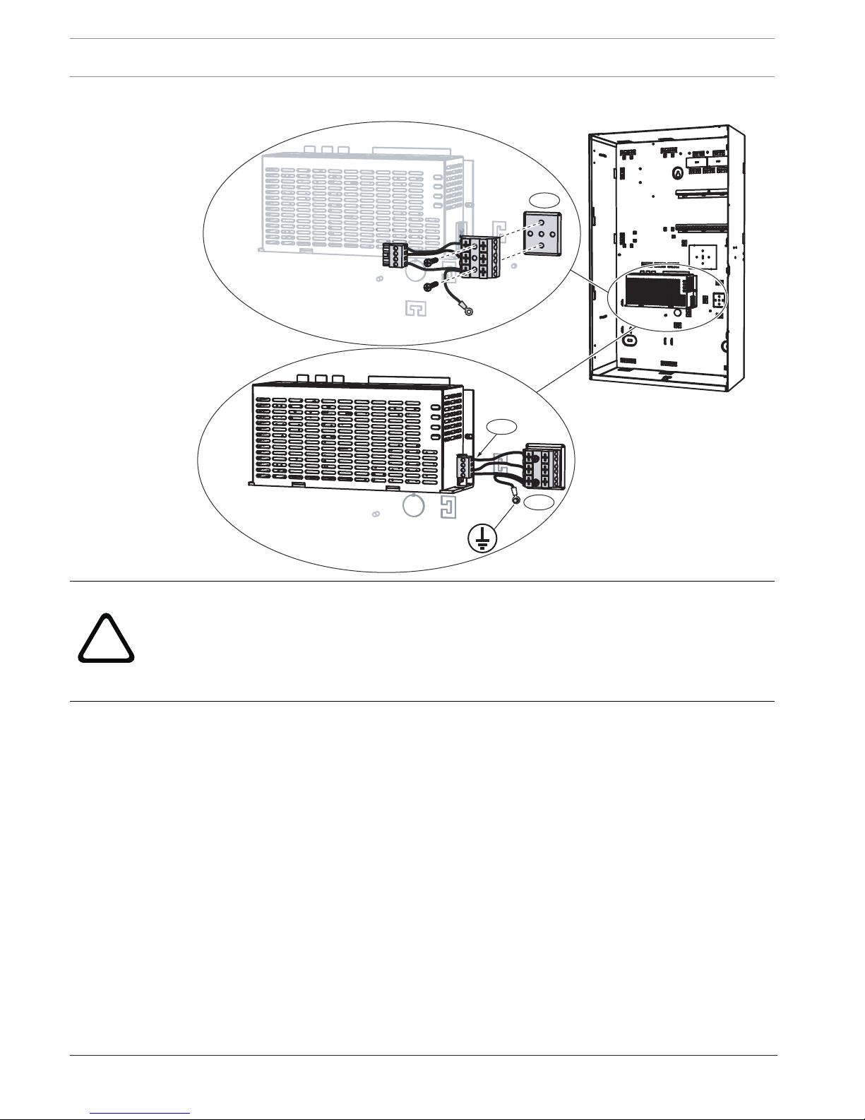
IPP-MAP0005 power supply ratings label
1. Mount the AC terminal block to the enclosure back wall into the corresponding mounting
holes as shown in the figure below and secure it with the supplied screws (1).
2. Plug the terminal block connected to the AC terminal block into the power supply as
shown in the figure below (2).
3. Connect the ground wire to the ground connection point of the enclosure back wall as
shown in the figure below (3).
22 en | Installation MAP 5000
2016.06 | 17 | F.01U.168.332 Installation manual Bosch Sicherheitssysteme GmbH
Installing the AC terminal block
1
3
2
!
Warning!
When installing the power supply, ensure that the ground wire from the AC terminal block is
connected to the ground connection point as shown in Installing the AC terminal block, page
22.
The ground wire from the AC terminal block to the power supply does not provide an earth
ground for the enclosure. It only provides an earth ground for the power supply.
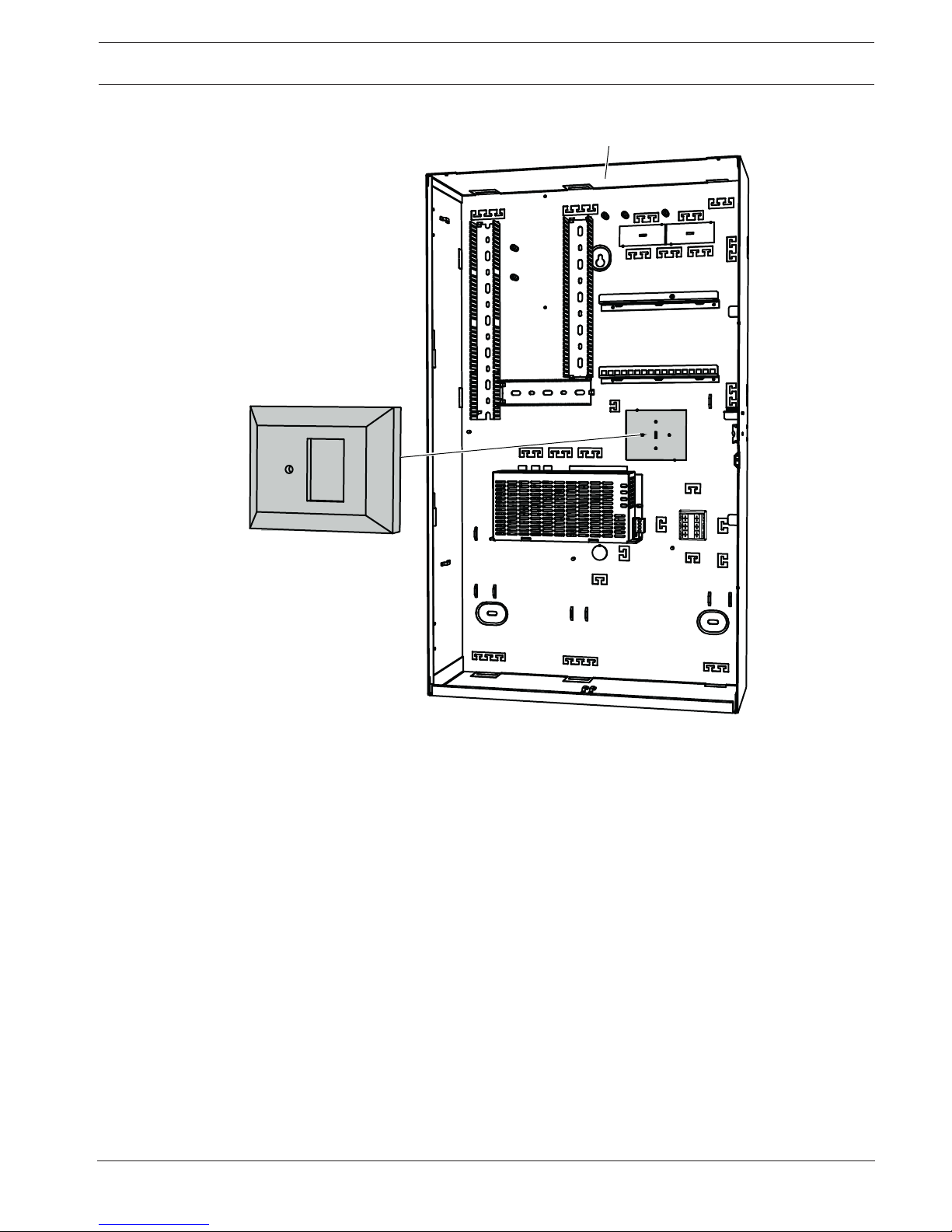
2.6 Installing the TAE box
4 If the TAE Box is not mounted on the wall behind the enclosure, mount the TAE Box to
the enclosure back wall either horizontally or vertically as desired.
MAP 5000 Installation | en 23
Bosch Sicherheitssysteme GmbH Installation manual 2016.06 | 17 | F.01U.168.332
Installing the TAE box
ICP-MAP0111
TAE
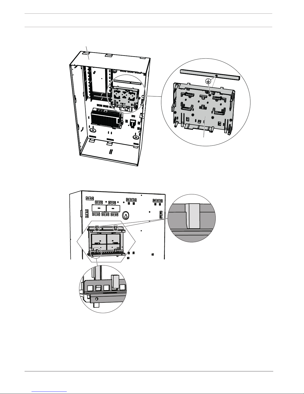
2.7 Installing the accessory mounting plate
1. Align the earth ground stud on the accessory mounting plate with the earth ground hole
on the top mounting rail in the upper right side of the enclosure wall as shown in the
figure below.
2. Slide the clips on the back of the accessory mounting plate onto the top and bottom
mounting rails.
24 en | Installation MAP 5000
2016.06 | 17 | F.01U.168.332 Installation manual Bosch Sicherheitssysteme GmbH
Aligning the accessory mounting plate
ICP-MAP0111
ICP-MAP0020
4 Ensure that the locking clips snap into the bottom mounting rail as shown in the figure
below.
Installing the accessory mounting plate
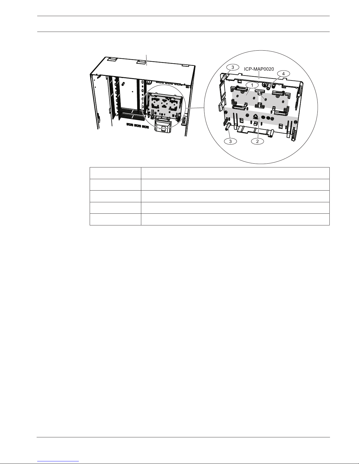
Refer to Accessory mounting plate overview, page 25 for the locations of the modules that
mount on the accessory mounting plate.
MAP 5000 Installation | en 25
Bosch Sicherheitssysteme GmbH Installation manual 2016.06 | 17 | F.01U.168.332
Accessory mounting plate overview
ICP-MAP0111
Element Description
1 Locations for ICP-MAP0017 12 V converters (two maximum)
2 Location for fuse plate (SIV) (one maximum)
3 Screw locations for AT 2000 communicator (one maximum)
4 Screw location for AT 2000 earth ground
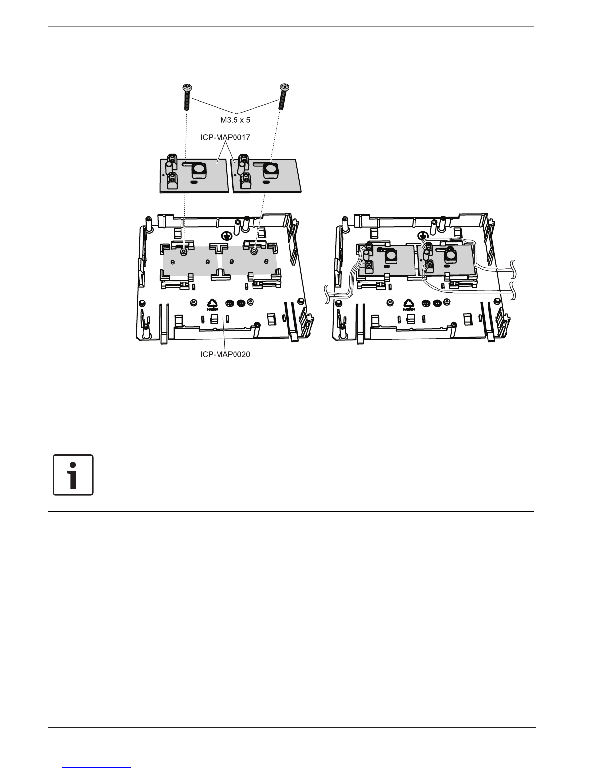
2.8 Installing the 12 V converter
1. Mount the ICP-MAP0017 12 V converter onto the accessory mounting plate as shown in
the figure below (screws not supplied).
2. Connect the field wiring to the terminal block of the 12 V converter as shown in the figure
below and leave the other ends unconnected.
26 en | Installation MAP 5000
2016.06 | 17 | F.01U.168.332 Installation manual Bosch Sicherheitssysteme GmbH
Installing the 12 V converter
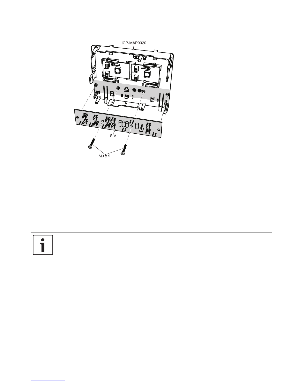
2.9 Installing the fuse plate (SIV)
1. Mount the fuse plate (SIV) onto the accessory mounting plate as shown in the figure
below (screws not supplied).
2. Connect the field wiring to the terminal block of the fuse plate (SIV) as shown in the
figure below and leave the other ends unconnected.
Notice!
Use the corresponding ratings for the fuses SI 1 ... SI 5. (minimum 250 mA, maximum 1 A
depending on the connected loads).
The overall current of all SIV outputs must not exceed the available maximum current of the
voltage output used.
MAP 5000 Installation | en 27
Bosch Sicherheitssysteme GmbH Installation manual 2016.06 | 17 | F.01U.168.332
Installing the SIV
2.10 Installing the AT 2000 communicator
The AT 2000 communicator mounts onto the ICP-MAP0020 accessory mounting plate over the
12 V converter (if installed). If the fuse plate (SIV) is mounted on the accessory mounting
plate, the communicator cannot be mounted on the same mounting plate.
1. Slide the right edge of the AT 2000 under the clips on the right-hand side of the
accessory mounting plate.
2. Gently push down on the left edge of the AT 2000 until it snaps into place under the
single clip on the left-hand side of the accessory mounting plate.
3. Insert the supplied grounding screw through the AT 2000 and the accessory mounting
plate, and fasten it into the top mounting rail.
Notice!
To ensure proper system grounding, you must insert the grounding screw through the AT
2000 and the accessory mounting plate.
 Loading...