

Bosch HPC Installation, Operation And Maintenance Manual
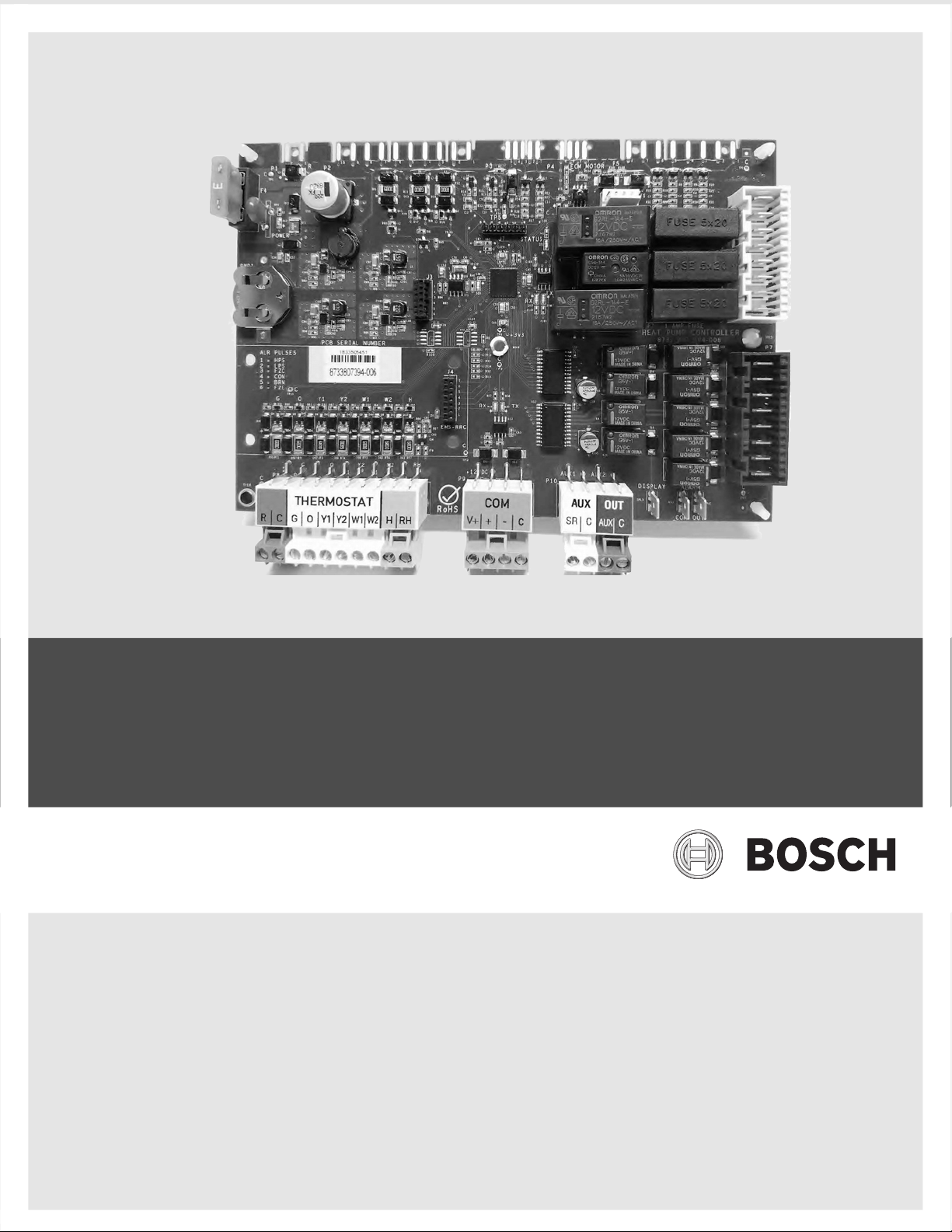
HPC
Heat Pump Controller
Installation, Operation, and Maintenance Manual
8733819577 (2019/02)

2 |
Heat Pump Controller
CONTENTS
Document Conventions .......................................................3
Key to Symbols............................................................ 3
Safety Warnings..................................................................3
Introduction........................................................................4
Product Description ..................................................... 4
Bosch EasyStart App.................................................... 5
Features..................................................................... 5
Specifications .............................................................5
Loop Pump Control (former Pump Valve Relay Kit) ...........6
Unit Configuration...............................................................7
Settings ..................................................................... 7
Alarm Mode ................................................................ 7
Configurable Hard Lockout............................................ 8
Fan Motor...................................................................8
System Operation ...............................................................9
Timers and Faults ........................................................ 9
Sequence of Operation.................................................9
Fan Operation ...........................................................10
Loop Pump Operation ................................................ 10
Reversing Valve Operation .......................................... 11
Comfort Mode........................................................... 11
Economy Mode.......................................................... 11
Emergency Heating Mode ........................................... 11
Heat Recovery Package (HRP) ..................................... 11
Dehumidification .......................................................12
Latching Mode Operation............................................ 12
Unlatching Mode (Factory Default)............................... 12
Alarm Terminal Wiring ...................................................... 33
Terminology .....................................................................34
Acronyms .................................................................34
Terms.......................................................................34
Decommissioning Information ........................................... 35
Check-Out Sheet...............................................................36
EasyStart Check-Out Sheet................................................ 37
Notes ...............................................................................38
System Protection.............................................................13
Consumer Enhanced Security...................................... 13
Compressor Demand (Y1 Call) ....................................13
Pressure Protection ................................................... 13
Brownout Protection .................................................. 14
Low Loop Water Protection Control (LLWPC) (Boilerless
Control) ................................................................... 14
Water Flow Detection ................................................. 14
Sensor Monitoring ..................................................... 14
Troubleshooting................................................................19
Invalid Thermostat Demands .......................................19
Replacement Parts..................................................... 19
Unit Status LED (Blink Code) Information...................... 20
Heating and Cooling ...................................................20
Heartbeat LED........................................................... 22
Thermistor Resistance Versus Temperature...................22
HPC Board Replacement and Installation ............................24
Contact Information ................................................... 24
Recommended Tools.................................................. 24
Model and Serial Number............................................24
HPC Board Replacement............................................. 24
Wiring Diagrams ...............................................................30
Electrical Box....................................................................32
Thermostat Connections....................................................33
Heat Pump Controller8733819577 (2019/02) Subject to change without prior notice
DOCUMENT CONVENTIONS
Key to Symbols
Warnings
Warnings in this document are identified by
a warning triangle printed against a gray
background. Keywords at the start of the
warning indicate the type and seriousness
of the ensuing risk if measures to prevent
the risk are not taken.
The following keywords are defined and can be
used in this document:
• DANGER indicates a hazardous situation that,
if not avoided, will result in death or serious
injury.
• WARNING indicates a hazardous situation
that, if not avoided, could result in death or
serious injury.
• CAUTION indicates a hazardous situation that,
if not avoided, could result in minor to
moderate injury.
• NOTICE is used to address practices not
related to personal injury.
Document Conventions | 3Heat Pump Controller
WARNING: This product can expose you to
chemicals including Lead and Lead
components, which are known to the State
of California to cause cancer and birth
defects or other reproductive harm.
For more information go to
www.P65Warnings.ca.gov.
CAUTION: When working on equipment,
always observe precautions described in
the literature, tags, and labels attached to
the unit. Follow all safety codes. Wear
safety glasses and work gloves. Use a
quenching cloth for brazing, and place a fire
extinguisher close to the work area.
Important Information
This symbol indicates important information
where there is no risk to property or people.
SAFETY WARNINGS
IMPORTANT: Read the entire instruction
manual before starting installation.
WARNING: Installation and servicing of this
equipment can be hazardous due to system
pressure and electrical components. Only
trained and qualified personnel should
install, repair, or service the equipment.
WARNING: Before performing service or
maintenance operations on the system, turn
off main power to the unit. Electrical shock
could cause personal injury or death.
8733819577 (2019/02)Heat Pump Controller Subject to change without prior notice
4 | Introduction
INTRODUCTION
Heat Pump Controller
Product Description
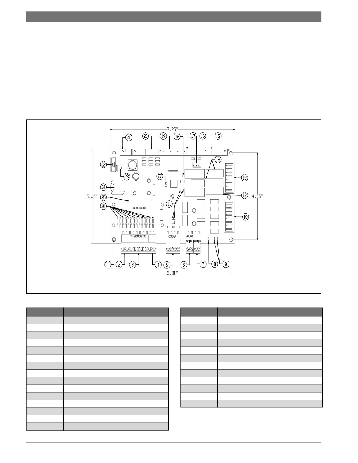
The Heat Pump Controller (HPC) as shown in
Fig. 1, is a Printed Circuit Board Assembly (PCBA)
that interfaces with the thermostat to ensure
desired functionality. It is designed to protect the
condenser coil, evaporator coil, compressor, and
blower motor by monitoring different states of its
switches and sensors.
This device provides time delays to prevent the
system from operating under extreme and
potentially hazardous conditions. The HPC
provides useful information to service personnel
for diagnosing unit operating conditions and faults
when they arise via the Bosch EasyStart app
interface.
Fig. 1 Heat Pump Controller
Item No. Description
1 HPC Ground Standoff
2 Thermostat Power Source
3 Thermostat Control Signals
4 Humidistat Control Signals
5 Comm Port RS 485
6 Electric Heat 1 Output
7 Electric Heat 2 Output
8 Display Output
9 Alarm Output (Dry N.O.)
10 Heat Pump Control Output
11 COMM Port Status LEDs
12 HRP Fuse (1 AMP)
13 High-Voltage Pump Outputs
14 Loop Pump Fuses (5 AMP)
15 P5 Termistor Input Plug
Item No. Description
16 Wi-FI Service Port
17 P4 ECM Motor Control Plug
18 Unit Status LED
19 P3 HRP Termistor Plug
20 P2 Heat Pump Safety Plug
21 P1 24VAC Power Supply Plug
22 Class II Voltage Fuse (3 AMP)
23 Power Status LED
24 Backup Battery (CR2032)
25 PCB Serial Number
26 Thermostat Control Signal LEDs
27 Heartbeat LED
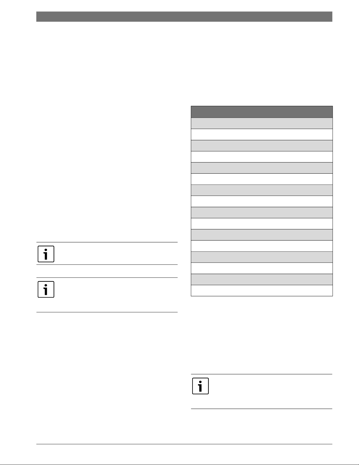
Table 1 Available Fault Snapshots
Heat Pump Controller8733819577 (2019/02) Subject to change without prior notice
Introduction | 5Heat Pump Controller
Bosch EasyStart App
The Bosch EasyStart app is a digital interface that
allows access to information from the HPC making
commissioning, configuring, and troubleshooting
easier. This application is available in the Google
Play Store, the Apple App Store, as well as the
Bosch Pro HVAC website (
www.boschprohvac.com).
Search for “Bosch EasyStart” in the appropriate
store for your device to download and launch the
app. Once launched, navigate through the legal
information, and then the user guide displays,
explaining how to connect the App and the heat
pump, as well as how to explore the features of the
Bosch EasyStart app.
The Bosch EasyStart app will only work on the
following devices: Android tablets with Android 4.0
operating system or higher, Apple iPads with iOS 8
or higher, and Windows 7.0 or higher laptops/PCs.
For more information refer to the website list in
the Bosch EasyStart app IOM.
Features
Thermostat (24VAC Rated) Digital Inputs
• Fan call (G) signal
• Reversing valve (O) signal
• Compressor Stage One (Y1) signal
• Compressor Stage Two (Y2) signal
• Electric heat Stage One (W1) signal
• Electric heat Stage Two (W2) signal
• Electric heat Emergency (W2/EM) signal
• Dehumidification call (H) signal
Analog Inputs
The following sensors are 10 KΩ @ 77°F
thermistors:
• Freeze Coax Sensor (FZC)
• Freeze Evaporator Sensor (FZE)
• Discharge Air Temperature (DAT)
• Return Air Temperature (RAT)
• Entering Water Temperature (EWT)
• Leaving Water Temperature (LWT)
• Discharge Refrigerant Temperature (DRT)
• Domestic Water Temperature (DWT)
• Auxiliary Output1 Aux Heat control (AUX1)
• Auxiliary Output2 Aux Heat control (AUX2)
• Alarm purposes dry contact normally open (NO)
(Pulse or Constant) (ALM)
Digital Outputs (Rated 208/230 VAC)
• Loop valve/pump control (5 Amp Max)
• Heat recovery pump control (3 Amp Max)
Blower Control Output
PWM 24VDC 80Hz
Service Communications (COMM) Ports (RS-485)
J1 WiFi
Visual Status LED Indicators
• Power status indication
• Alarm status indication
• Controller heartbeat indication
• Thermostat demand indication
• RS-485 RX/TX indication
Voltage Protection
• Surge and transient protection circuitry
• Brownout protection mode
Safeties Monitoring
• High Pressure Switch (HPS)
• Low Pressure Switch (LPS)
• Monitoring of multiple sensors
Certification
ETL 101071399CRT-011
Field Updates
The HPC software can be updated in the field via the
Bosch EasyStart app.
Specifications
Power
24 VAC ± 25%, 50-60 Hz, 2 VA of standby power
consumption (single class II 75 VA or 100 VA option
available).
Physical Description
Printed circuit board and plastic standoffs
Environmental Operating Range
-40°F to 176°F (-40°C to 80°C); 10% to 90% relative
humidity, non-condensing. All controls are conformal
coated for environmental protection.
For Type II (10 KΩ@ 77°F) thermistor
temperature curve, refer to Fig. 12.
Digital Outputs (Rated 24VAC)
• Compressor 1st step control (CC1)
• Compressor 2nd step control (CC2)
• Reversing valve control (RV)
Weight
0.54 lbs. (0.25 Kg)
Overall Dimensions
• 7.25" (width) by 5.06" (height) by 3" (recommended
panel depth)
• 184mm (width) by 129mm (height) by 76mm
(recommended panel depth)
8733819577 (2019/02)Heat Pump Controller Subject to change without prior notice

6 | Introduction
Mounting Hole Dimensions
Four (4) mounting holes in rectangular pattern with
dimensions between them as follows:
• 6.81" (width) by 4.65" (height).
• 173mm (width) by 118mm (height).
WARNING:
Chassis Ground
Ensure metal standoff is properly secured to the
chassis of the unit through a fastener. The HPC
will obtain a chassis ground by way of a metal
standoff connected to both the (C-GND) and (C)
terminals of the Printed Circuit Board (PCB).
Improper grounding could result in potential
electrical shock and/or Equipment malfunction.
Electrical shock could cause personal injury or
death.
Loop Pump Control (former Pump Valve
Relay Kit)
A loop pump control relay has been integrated into
the HPC board. The loop pump control can be used
to energize a field-installed pump or solenoid valve
when there is a call for compressor operation. This
loop pump control relay is used to switch 208/240
VAC signals ON/OFF (depending on the supply
voltages).
Heat Pump Controller
NOTICE: The loop pump control relay output is
208/240 VAC at 5 A; ensure the pump or valve
being connected is rated to this specification.
Heat Pump Controller8733819577 (2019/02) Subject to change without prior notice

UNIT CONFIGURATION
Settings
The Bosch EasyStart app is used to configure available features of the HPC as follows:
HPC Settings Default Settings
Freeze Protection Strategy 15°F–26°F 26°F
Cooling CFM per TON 300–450 400 CFM/Ton
Heating CFM per TON 300–450 375 CFM/Ton
Fan Only CFM reduction 50–100% 80%
Dehumidification CFM reduction 15–40% 15%
Heat Recover Package Enabled or Disabled Disabled
Heat Recovery Setpoint 110°F–140°F 120°F
Heat Recovery Sample Rate 2–6 Samples/Hr 3 Samples/Hr
Electric Heat Size None, 5kW, 10kW, 15kW, 20kW None
Low Loop Water Protection Enabled or Disabled Disabled
Unit Configuration | 7Heat Pump Controller
Low Loop Control Setpoint 20°F–50°F 34°F
Loop Pump Compressor Delay 30–240 seconds 30s
Mode of Compressor Operation Comfort or Economy Comfort
Down-Staging Latched or Unlatched Unlatched
Number of Lockouts 2–4 Strikes 3 Strikes
Lockout Reset (Y1) signal or (R) (Y1)
Units of Temperature °F or °C °F
Alarm Type Constant or Pulse Pulse
Date MM/DD/YYYY
Time HH:MM
High Efficiency Mode Enable or Disabled Disabled
Compressor Runtime Reset Write Only
Model Number
(from the Unit Data Plate)
Serial Number
(from the Unit Data Plate) 1234-567-891011-1213141516
SM036-1VTC-FRTADCCMGXXXXXD7HXXX4XXXXSNA
Table 2 HPC Settings
Refer to the “Updating the Firmware and
Configuring Unit Settings” section on page #26
for details on accessing these settings.
NOTICE: Keep the HRP configuration setting
set to disabled if there is no domestic water
supply available.
Alarm Mode
The HPC has a fault alarm that can be configured
(via the Bosch EasyStart app) as constant or
pulsed. Constant configuration will energize and
latch the alarm output. The pulse alarm setting will
allow the alarm relay to pulse the alarm in sync
with the status LED indicator.
8733819577 (2019/02)Heat Pump Controller Subject to change without prior notice

8 | Unit Configuration
Heat Pump Controller
To exit a hard lockout, power must be reset at the
(Y) terminal (factory setting) or (R) terminal
(configurable via the Bosch EasyStart app). The
alarm, display, and status LED indicator outputs
should only pulse the latest fault. Once the latest
fault is cleared, the HPC will pulse for any
remaining faults recorded.
Refer to “Alarm Terminal Wiring” on page #33.
Configurable Hard Lockout
The controller can be configured from two to four
faults for a hard lockout condition (configurable
via the Bosch EasyStart app). If the controller
senses the same fault for the number of times
configured within one hour from the first fault, the
controller will enter a hard lockout. Example:
When configured to four strikes, if the control
experiences four of the same faults within one
hour then the controller will enter a hard lockout.
Clearing a Hard Lockout
To clear a hard lockout condition, power to the (R)
terminal may be reset at the circuit breaker panel,
or the heat/cool call to the (Y1) terminal may be
reset from a connected thermostat (default). The
HPC can be configured for either reset option
using the Bosch EasyStart app.
The controller has a heating CFM/Ton low limit of
400 for electric heat operation. If the effective CFM
is lower than this value the controller will override
the effective CFM with the verified CFM value and
latch it to 400 Cubic Feet per Minute (CFM)/Ton.
The controller has a “Most Efficient Mode”
configuration. The function of this is to enable the
unit to run at the most efficiently-rated CFM values
as tested in our labs.
Fan Motor Table
The Fan motor is specified in the third and fourth
digits of the code string nomenclature.
• SM024 = 2 Ton 2-step unit
• SM036 = 3 Ton 2-step unit
• SM048 = 4 Ton 2-step unit
• SM060 = 5 Ton 2-step unit
• SM070 = 6 Ton 2-step unit
Fan Motor
The installer can modify the total Cubic Feet per
Minute (CFM)/Ton via the Bosch EasyStart app as
shown in the table below.
Max
Installer
CFM per
State
Ton
COOLING 450 300 25 400
HEATING 450 300 25 400
Table 3 CFM Configure
The controller calculates the required flow rate
(CFM) based on the unit’s model and size. The
controller has a cooling CFM/Ton lower limit of
270. If effective CFM is lower than this value, the
controller will override the effective CFM with the
verified CFM preventing it from being lower than
270 CFM/Ton. The cooling verified CFM will apply
to the cooling and the dehumidification modes of
the operation.
Min
Installer
CFM per
Ton
Step
Installer
CFM
Default
Heat Pump Controller8733819577 (2019/02) Subject to change without prior notice
System Operation | 9Heat Pump Controller
SYSTEM OPERATION
Timers and Faults
Random Start-Up Delay (Power)
This delay prevents multiple units sharing the same
electrical circuit or network from starting at the
same time. It ensures that the Heat Pumps
connected to the same electrical circuit do not
demand a high inrush of current simultaneously
when starting up after a power failure. The random
start time delay is in the range of 200–300
seconds. In test mode, the random start time delay
is reduced to 10 seconds. Random Start-Up delay
only runs during start up or after power has been
completely removed. It does not take effect after a
brownout condition.
Test Mode
Test mode decreases all delay timers to 10
seconds. Test mode is only for testing purposes
and serves no function to the end user of the
equipment. In test mode, the alarm relay and
display relays will pulse during both soft lockout
and hard lockout. If a soft lockout alarm is cleared,
both relays will stop pulsing. The controller will
exit test mode after 20 minutes or upon a power
cycle.
Snapshot Record
The controller constantly monitors all thermostat
sensors and thermostat demand values. The
controller also has an additional feature where the
latest fault snapshot will be saved to the
controller. When a new fault occurs the snapshot
will be saved and overwrite the previous snapshot.
The following faults in the table below will be
available in the snapshot record.
Available Fault Snapshots
High-Pressure Hard Lockout Fault
Low-Pressure Hard Lockout Fault
Freeze Coaxial Hard Lockout Fault
Condensate Overflow Hard Lockout Fault
Brownout Voltage
Freeze Evaporator Hard Lockout Fault
Freeze Evaporator Temp Sensor Open
Freeze Coaxial Temp Sensor Open
Freeze Evaporator Temp Sensor Open
High Leaving Water Temperature Fault
Fan Motor Hard Lockout Fault
The test mode command can only be set via the
Bosch EasyStart app.
If the controller is set to “TEST” mode via Bosch
EasyStart app, the safety delays will be reduced
to 10 seconds. The controller will automatically
exit test mode after 20 minutes.
Anti-Short Cycle Delay (ASC)
This feature protects the compressor from short
cycling if the (Y1) call is removed and set or if a
refrigerating circuit level fault is sensed to the
point that the compressor shuts down. The ASC is
300 seconds during normal operation and 10
seconds in test mode. The ASC will not be in effect
during a Random Start-Up delay.
Fan Motor Soft Lockout Fault
Freeze Evaporator Soft Lockout Fault
Freeze Coaxial Soft Lockout Fault
High-Pressure Soft Lockout Fault
Low-Pressure Soft Lockout Fault
Table 4 Available Fault Snapshots
Sequence of Operation
Cooling Mode
Energizing the “O” terminal energizes the unit
reversing valve thus placing the unit into cooling
mode. The fan motor starts when the “G” terminal
is energized.
The fan motor will take 30 seconds to ramp up
to operating speed and will run at fan only rated
air flow as long as there is no call for compressor
or heater operation.
8733819577 (2019/02)Heat Pump Controller Subject to change without prior notice
10 | System Operation
When the thermostat calls for first-stage cooling
(Y1) the loop pump or solenoid valve, if present, is
energized and the first stage of the compressor
capacity starts. The fan ramps up to the first stage
of cooling air flow in 30 seconds.
Heat Pump Controller
When using a 2-cool, 3-heat thermostat both the
W1 & W2 on the Heat Pump and W2 & EM on
the thermostat must be connected together via
a jumper.
Some options will have a built in delay, so
compressor operation is not immediate.
When the thermostat calls for second-stage
cooling (Y2) the second stage (or full compressor
capacity) is initiated. The fan ramps up to full
cooling air flow.
Once the thermostat is satisfied, the compressor
shuts down and the fan ramps down to either
fan-only mode or off over a span of 30 seconds.
Note that a fault condition initiating a lockout will
de-energize the compressor irrespective of
which stage is engaged.
Heating Mode
The first two stages of heating (Y1 & Y2) operate in
the same manner as cooling but with the reversing
valve de-energized. On a call for auxiliary heat
(W1), the fan ramps up to auxiliary heat air flow
immediately and the electric heater package is
energized along with the compressor.
As the thermostat is satisfied, the heaters will shut
off as soon as W1 is de-energized, and the
compressors will remain on until the thermostat
stages are satisfied.
Fan Operation
The fan starts anytime the fan command signal (G)
or a demand for cooling/heating is received on the
thermostat interface block. The fan will run at its
minimum factory speed of 80% in fan-only mode.
The fan remains on during lockouts if there is a
demand from the thermostat. The fan motor will
take 10 seconds to ramp up to operating speed.
The fan will be commanded to run at fan-only air
flow as long as there is no call for mechanical
heating/cooling or electric heating operations.
The fan can be configured via the Bosch EasyStart
app to run in a range of CFM from 300 to 450 in 25
CFM increments. The controller has airflow
profiles (CFM) for both heating and cooling
operations.
Loop Pump Operation
The Loop Pump (LP) energizes 30 seconds
(configurable from 30 seconds to 240 seconds via
the Bosch EasyStart app) prior to compressor
operation during a mechanical heating or cooling
demand. The LP remains on during low loop water
temperature protection and a high Leaving Water
Temperature (LWT) warning. The loop pump stays
off for the following faults and delay timers:
If the unit compressor locks out for any reason
at this time, the electric heaters will continue to
function normally.
Once the thermostat is satisfied, the compressor
shuts down and the fan ramps down either
fan-only mode or off over a span of 30 seconds. If
the thermostat has two different output points,
one for Auxiliary Heat and a different one for
Emergency Heat the two outputs must be
terminated on W1 units equipped with one stage
of electric heat.
• High Pressure Switch fault
• Low Pressure Switch fault
• Freeze Coaxial Coil fault
• Freeze Evaporator Coil fault
• Brownout fault
• Condensate Overflow fault
• Anti-Short Cycle delay
• Flow delay
HPC will command the Loop Pump (LP) output to
energize the pump motor whenever a heating or
cooling command (Y1) is received.
Heat Pump Controller8733819577 (2019/02) Subject to change without prior notice
System Operation | 11Heat Pump Controller
The Loop Pump output of the HPC will energize the
pump directly. 230 VAC to 208 VAC on the HPC
pump outputs will be present (voltage dependent
on supply).
WARNING: Before performing service or
maintenance operations on the system, turn
off the main power to the unit. Electrical
shock could cause personal injury or death.
Reversing Valve Operation
The Reversing Valve (RV) is energized when the
controller receives a command on the (O)
terminal. The unit will run in cooling mode when
the (RV) is energized and heating when the (RV) is
not energized. The HPC checks for an (RV) demand
every 30 seconds.
Comfort Mode
In comfort mode the controller satisfies demand as
call is presented, regardless of energy
consumption, to satisfy space comfort levels. In
comfort mode, after the first stage of cooling/
heating the system turns on the second stage of
cooling/heating, with a 10-second delay, following
a call for second stage of cooling/heating.
Economy Mode
In economy mode the controller satisfies demand
as call is presented, taking energy consumption
into consideration to operate the compressor. In
economy mode after the first stage of cooling/
heating, the second stage is initiated by calculating
progress of the current state, regardless of a call
for the second stage of cooling/heating. If there is
gradual progress with first stage, the controller
will not initiate second stage of the compressor.
Economy mode is only available if the Discharge Air
Temperature (DAT) sensor is functional.
If the DAT sensor fails, a warning message will
broadcast to the Bosch EasyStart app and
economy mode will be disabled.
Emergency Heating Mode
Emergency heating mode is an electrical heating
feature that is used in place of mechanical heating
when the mechanical heating (Y1 or Y2) is not
available. The unit will initiate the first stage of
electric heat immediately and will start the next
stage of electric heat (stage 2) after a 180-second
delay.
Heat Recovery Package (HRP)
The HRP can be used to heat potable water during
unit operation (heat that would otherwise be
wasted from the compressor discharge gas). The
HRP consists of three major components:
• Double wall, vented refrigerant to water heat
exchanger
• HRP pump
• Control circuit
Conditions for the HRP to operate are as follows:
1. Discharge Refrigerant Temperature (DRT) is at
least 10°F greater than the domestic hot water
temperature (DWT). The DWT set point is
configurable between 110–140°F, via the
Bosch Easy Start app.
2. Loop Pump (LP) and compressor are both
energized.
3. Domestic water temperature drops 2°F below
set point (default is 120°F). The controller will
run the pump until the demanded set point is
satisfied. The pump will run four times/hour via
(configurable from two to six times/hour via
the Bosch EasyStart App) in 90-second
intervals to determine whether or not demand
for hot water is needed.
The temperature of the discharge gas from the
compressor will be monitored once compressors
are energized. Once discharge gas is hot enough to
provide useful heat to the domestic water tank, the
circulating pump will be enabled, drawing water
from the tank, through the HRP heat exchanger
and the depositing the heated water back into the
tank. If the water temperature reaches the set
point (default is 120°F), the circulating pump is
disabled to prevent over heating of the domestic
water. The HRP is provided with an on/off switch
in case the end user desires that the HRP be
inactivated (typically during the winter months
when space heating is most important).
8733819577 (2019/02)Heat Pump Controller Subject to change without prior notice

12 | System Operation
Heat Pump Controller
In case of DWT/DRT sensor failure, the HRP
operation will be disabled.
NOTICE: Keep the HRP configuration setting
set to disabled if there is no domestic water
supply available.
WARNING: Before performing service or
maintenance operations on the system, turn
off the main power to the unit. Electrical
shock could cause personal injury or death.
Dehumidification
During cooling operation only, if the controller
senses a signal on the (H) terminal of the
thermostat interface block the fan CFM output will
be reduced by 15% (adjustable). The fan CFM
reduction percentage is adjustable from 15% to
40% reduction from nominal via the Bosch
EasyStart app.
During latching mode operation, the unit will
fasten the two compressor outputs together until
the demand is satisfied. If the thermostat removes
the second-stage demand, the HPC will keep the
second stage of compressor enabled until demand
is satisfied.
Unlatching Mode (Factory Default)
During unlatching mode the unit will cycle the
compressor outputs according to the thermostat
demand. The unit will downstage from secondstage compression to first stage when the demand
for second stage is dropped by the thermostat (Y2
and Y1 call to only Y1 call).
The controller has a minimum 270 CFM/Ton
requirement. The controller will not allow the
CFM/Ton to fall below this minimum even If the
reduction percentage calls for a lower CFM/Ton
amount.
Latching Mode Operation
The latching feature enforces how a HPC stages
down the multiple stages of heating and cooling. A
WSHP condenser coil uses water as medium for
exchanging heat with the refrigerant. Controlling
the stage down process will result in benefits to
the performance and efficiency of the system. As
the name implies, the maximum demanded stage
is latched on until the thermostat is satisfied at
which time all heating or cooling calls are
terminated. Many thermostats are designed for Air
Source appliances and the medium for exchange
(air) can usually provide heat exchange; however,
for ground loops used in WSHP can become
saturated after long run times. Latching is used in
WSHP applications as a means to “rest” the
ground loop between cooling and heating cycles
thus increasing the capacity for heat exchange.
Performance, efficiency, and comfort provided by
a WSHP will largely be maintained by preventing
the degradation of the loop’s physical heat
exchange properties.
Heat Pump Controller8733819577 (2019/02) Subject to change without prior notice
 Loading...