

Bosch HMV9302, HMV9307, HMV9305, HMV9303, HMV9306 Installation Instructions Manual
Household Appliances
Over-the-Range Microwave
Installation Instructions
For Models: HMV9302, HMV9303, HMV9305, HMV9306, HMV9307
PLEASE READ ENTIRE INSTRUCTIONS BEFORE PROCEEDING
IMPORTANT: Save these instructions for the local electrical inspector’s use.
INSTALLER: Please leave these Installation Instructions with this unit for the owner.
OWNER: Please retain these instructions for future reference.
Printed in Korea
P/No.: 3828W5U0503
2
YOUR SAFETY FIRST
BEFORE YOU START
• Proper installation is the installer's responsibility!
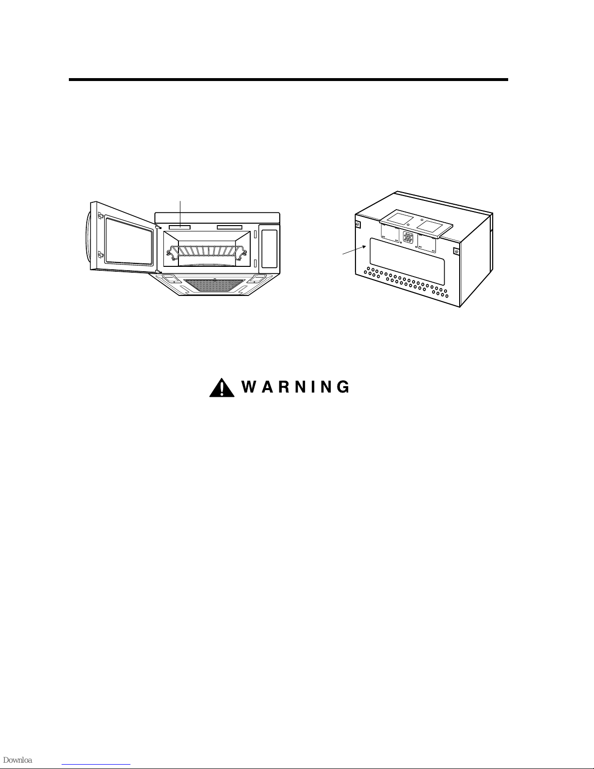
– Read the entire manual before you begin. The Model number label is located on the oven front. See Figure 1.
Mounting plate is located on back side of microwave oven. See Figure 2.
BE SURE TO READ THE FOLLOWING SAFETY INSTRUCTIONS:
FOR YOUR SAFETY:
• You will need TWO people to install this oven. It is heavy and could cause personal injury if not handled properly.
The dimensions of the oven are as follows:
Height : 16
7/16 inches
Width : 29
15/16 inches
Depth : 15
5/8 inches
Weight : 60 lbs.
• Avoid Electrical Shock!
– Before you drill into the wall, note where electrical outlets are and where electrical wires might be concealed
behind the wall. YOU COULD GET AN ELECTRIC SHOCK if you contact electrical wires with your drill bit.
– Locate and disconnect the power to any electrical circuits that could be affected by installing this oven.
IF YOU DO NOT DISCONNECT THE POWER, YOU COULD GET AN ELECTRIC SHOCK.
• ELECTRICAL RATING OF THIS OVEN : 120V AC 60Hz.
– You need a DEDICATED 120V, 60Hz, AC only, 15 or 20A, fused electrical supply (located in the cabinet above
the microwave as close as possible to the microwave) serving only the microwave.
Mounting
plate
( Remove from
oven to install. )
Back of oven
Figure 1 Figure 2
Model Number Label
WARNING
3
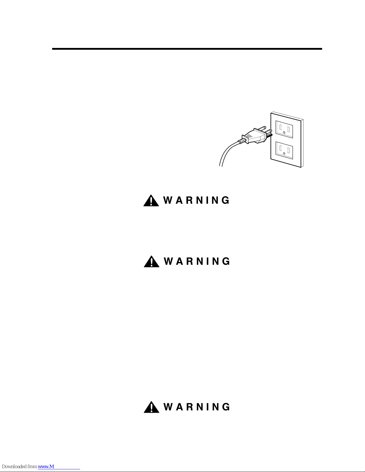
• THIS APPLIANCE MUST BE GROUNDED!
– If there is an electrical short circuit, grounding reduces the risk of electrical shock by providing an escape wire
for the electric current. This appliance is equipped with a cord having a grounding wire with a grounding plug.
• Place the plug into a properly installed and grounded outlet. See Figure 3.
• Do not use an extension cord.
• Keep the power cord dry and do not pinch or crush it.
• DO NOT, UNDER ANY CIRCUMSTANCES, REMOVE THE
POWER SUPPLY CORD GROUNDING PRONG!
This appliance MUST be grounded!
If you use the grounding plug improperly, you risk electric shock!
– Check with a qualified electrician if you are not sure whether the oven is properly grounded or if you do not
completely understand the grounding instructions.
DO NOT USE A FUSE IN THE NEUTRAL OR GROUNDING CIRCUIT.
Improper grounding could result in electric shock or other personal injury.
SAVE THESE INSTRUCTIONS FOR THE LOCAL ELECTRICAL INSPECTOR'S USE.
• DO NOT EXPOSE YOURSELF TO EXCESSIVE MICROWAVE ENERGY!
– DO NOT try to operate the microwave oven with the door open.
– DO NOT tamper with or defeat the safety interlocks.
– DO NOT place objects between the microwave oven front face and the door.
–
DO NOT allow soil or cleaner residue to build up on the flat surfaces around the microwave oven door.
– DO NOT operate the microwave oven if it is damaged.
– The microwave oven door must close properly to operate safely.
– DO NOT USE THE MICROWAVE OVEN:
• If the door is bent.
• If the hinges or latches are broken or loose.
• If the door sealing surfaces or glass is broken or cracked.
– DO NOT ATTEMPT TO ADJUST OR REPAIR THE OVEN YOURSELF!
It should be adjusted and repaired by a qualified technician who can check for microwave leakage after
repairing the oven.
If you do not use the microwave oven as instructed,
you could be exposed to excessive microwave energy.
YOUR SAFETY FIRST
PROPERLY POLARIZED AND
GROUNDED OUTLET
Three-Pronged (Grounding) Plug
Figure 3
WARNING
WARNING
WARNING
4
• MAKE SURE YOU HAVE ENOUGH SPACE AND SUPPORT.
– Mount the oven against a flat, vertical wall, so it is supported by the wall. The wall should be constructed of
minimum 2" x 4" wood studding and 3/8" thick drywall or plaster/lath.
– ATTACH AT LEAST ONE of the two lag screws supporting the oven to a vertical, 2" x 4" wall stud.
– DO NOT mount the microwave oven to an island or peninsula cabinet.
– BE SURE the upper cabinet and rear wall structures are able to support 150 lbs., plus the weight of any items
you place inside the oven or upper cabinet.
– Locate the oven away from strong draft areas, such as windows, doors, and strong heating vents.
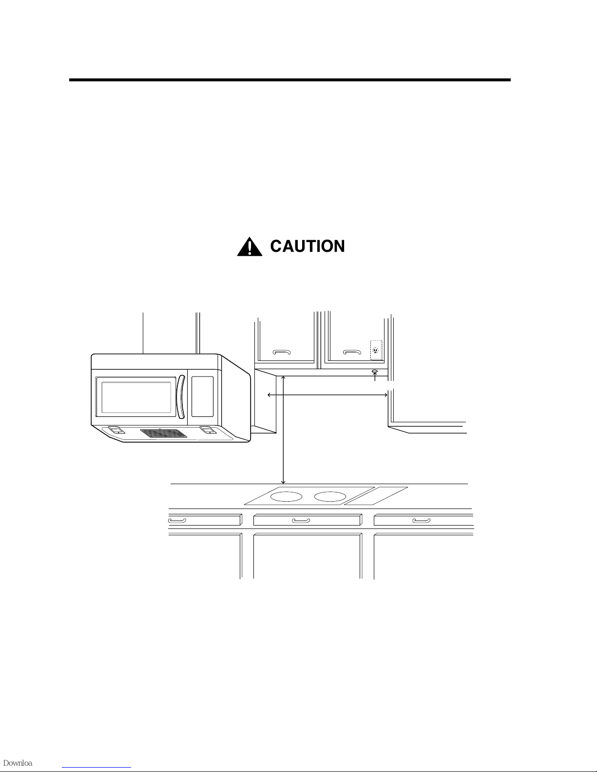
– BE SURE you have enough space. See Figure 4 below for minimum vertical and horizontal clearance.
If you do not mount the oven as instructed,
you risk personal injury and/or property damage.
CAUTION
•
Before you begin installing the oven, PLACE A PIECE OF THE CARTON OR OTHER HEAVY
MATERIAL (such as a blanket) over the countertop or cooktop to protect it. Do not use a plastic cover.
Failure to protect these surfaces could result in property damage.
YOUR SAFETY FIRST
30" min. cabinet opening width
30" min. clearance from bottom
of cabinet to cooking surface
or countertop
(Use templates included
with installation instructions)
Grounded Outlet
(inside upper cabinet)
Power Supply Cord Hole
Figure 4
CAUTION
5
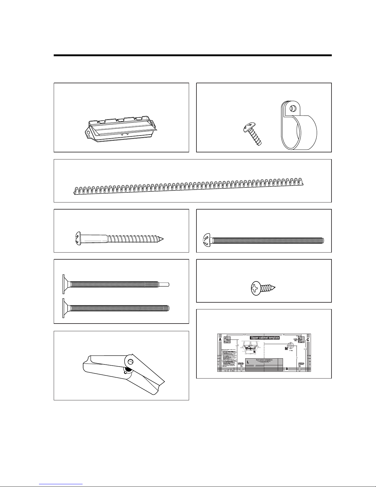
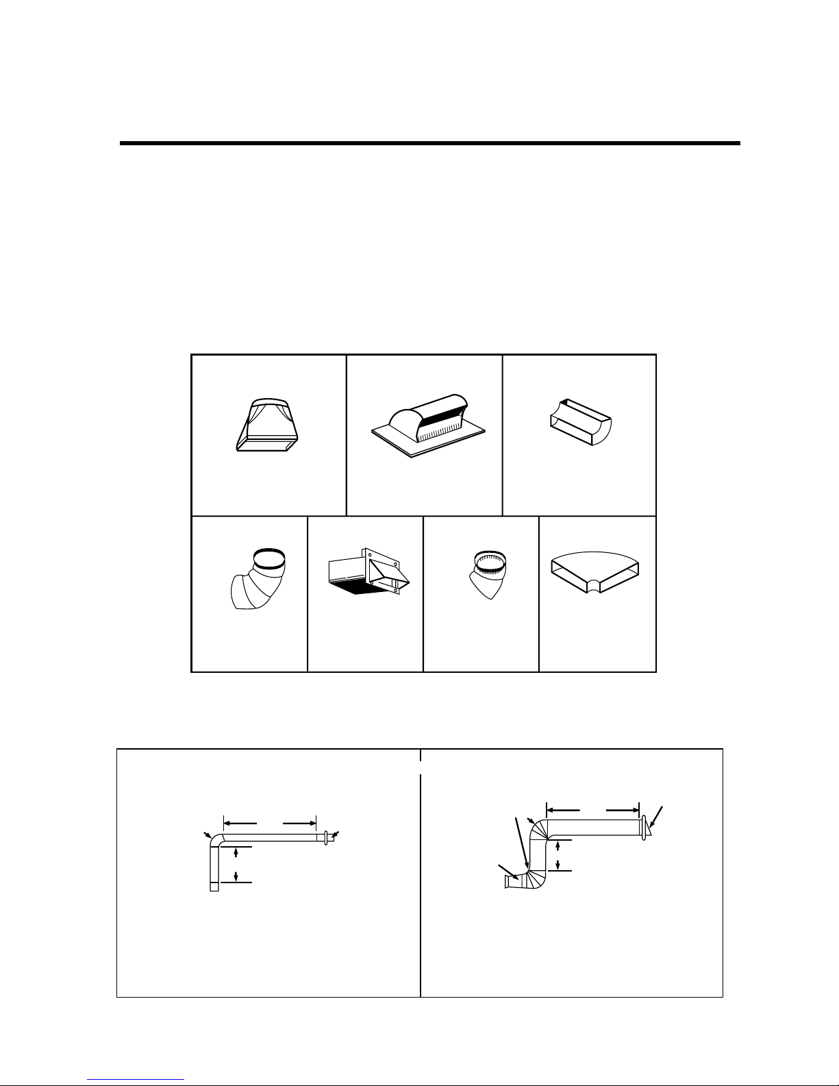
THE FOLLOWING PARTS ARE SUPPLIED WITH THE OVEN:
PARTS, TOOLS, MATERIALS
Damper/duct connector
(for roof vented or wall vented installation)
Not Actual Size
Four 1/4" x 2" lag screws - Actual Size
(for wall stud holes)
Four 1/4" x 3" toggle bolts - Actual Size
(for drywall holes)
Two 1/4" x 3" bolts - Actual Size
OR
(for securing to the upper cabinet)
Four spring toggle heads - Actual Size
(for the toggle bolts)
Left side
Right side
centerline
6"
4"
8"
12"
10-
8-
11
Roof-venting installation
Upper-cabinet template
B
C
D
10-
3
16
One upper cabinet template - Not Actual
Size
Two tapping screws - Actual Size
(for attaching the damper duct connector)
One power cord clamp bushing - Actual Size (for the cord hole in a metal upper cabinet)
One power cord clamp and
One dark-colored mounting screw
(to hold the power cord)
Actual Size
NOTE: Depending on your ventilation requirements, you may not use all of these parts.
NOTE: You need to install at least one lag screw into a 2" x 4" stud and four anchor bolts into the wall,
and the mounting area must meet the 150 lbs. weight requirement.
6
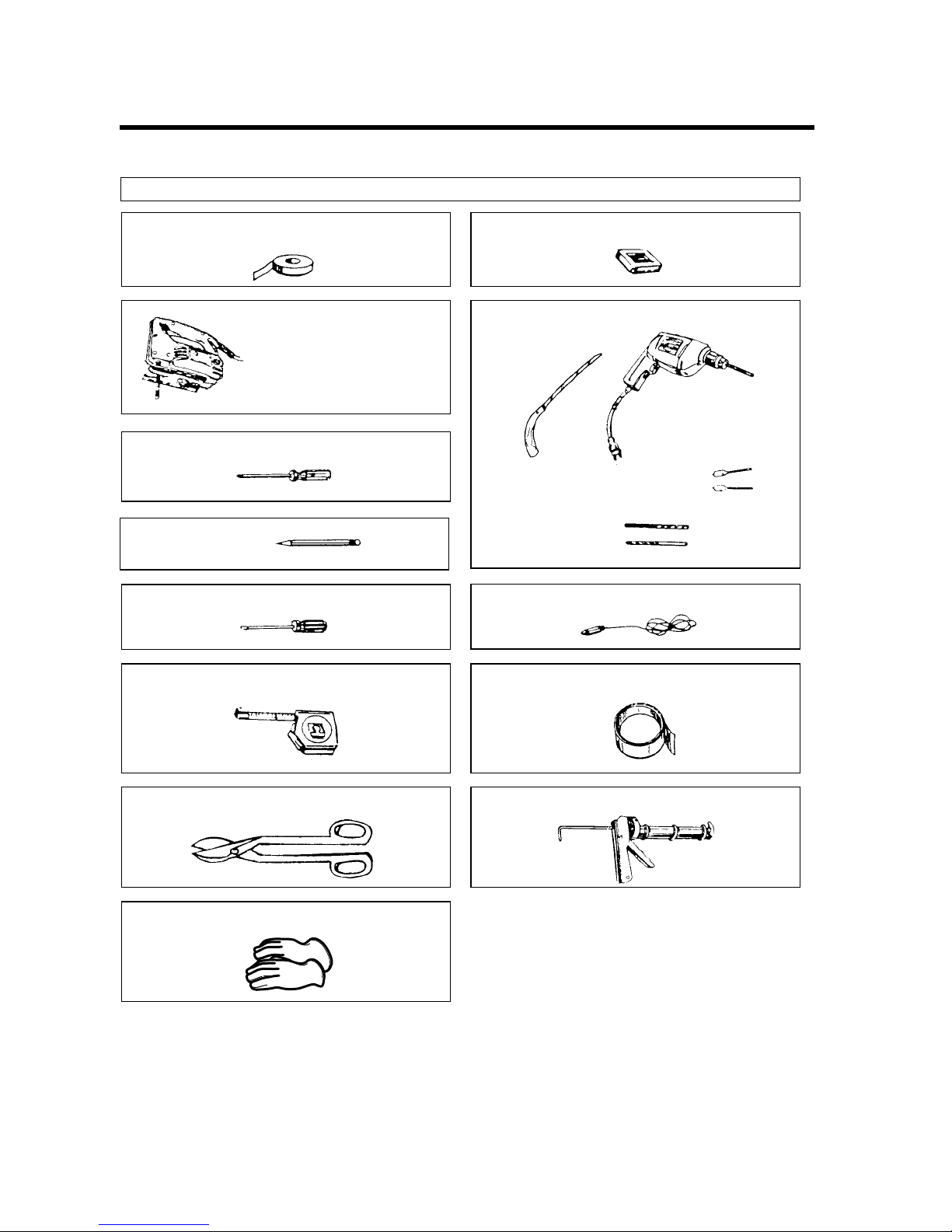
YOU WILL NEED THE FOLLOWING TOOLS AND MATERIALS FOR THE INSTALLATION:
Carton or other heavy material for covering the counter top.
• If you have brick or masonry walls, you will need special hardware and tools.
• The ductwork you need for the installation is not included. All wall and roof caps must have a back-draft damper
(shown on page 5).
PARTS, TOOLS, MATERIALS
Clear tape
(for taping the templates to the wall)
Stud finder or thin nail.
Saber saw (for cutting vent
holes for roof or wall venting)
Keyhole saw (for the power cord hole)
Electric drill
3/8" and 3/4" wood drill bits
1/2" and 3/16"
drill bits
Phillips screwdriver
Pencil
Flat blade screwdriver
Measuring tape (metal preferred)
Small side cutters or tin snips
Caulking gun
Plumb line
Duct Tape
Gloves
7
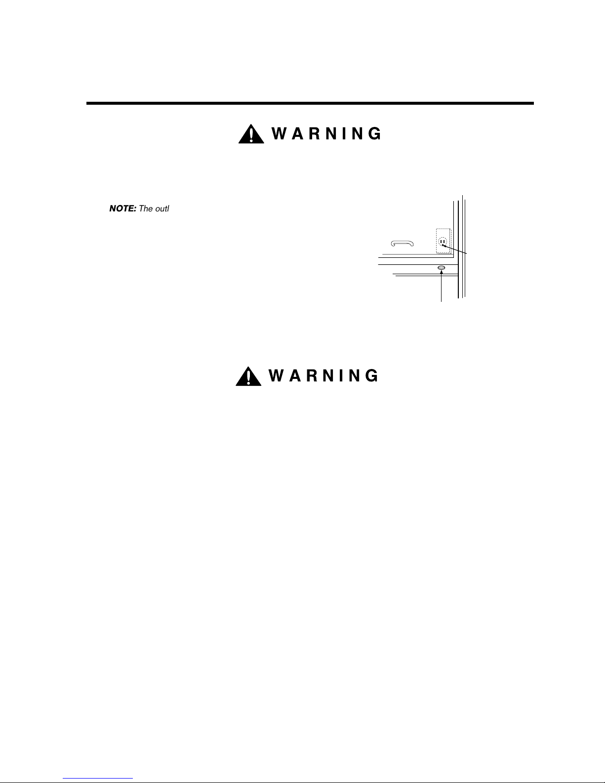
AVOID ELECTRICAL SHOCK! THIS APPLIANCE MUST BE GROUNDED!
1. Locate the grounded electric outlet for this oven in the cabinet
above the oven, as shown in Figure 4 Detail.
2. You will cut the power-supply-cord hole (shown in Figure 4 Detail)
later when you prepare the wall and upper cabinet in Step 4.
Improper grounding could result in
electric shock or other personal injury.
• DO NOT, UNDER ANY CIRCUMSTANCES, REMOVE THE POWER SUPPLY
CORD GROUNDING PRONG! This appliance MUST be grounded!
STEP 1: PREPARE THE
ELECTRICAL CONNECTIONS
Grounded Outlet
( Inside Cabinet )
Upper
Cabinet
Power-Supply-Cord Hole
Figure 4 Detail
WARNING
WARNING
NOTE: The outlet should be on a circuit dedicated to the
microwave oven 120V, 60Hz., AC only with a 15 or
20A fused electrical supply.
NOTE: Do not use an extension cord.
Keep the power cord dry and do not pinch or crush it.
IMPORTANT: If you do not have the proper wall outlet, you
MUST have one installed by a qualified
electrician.
8
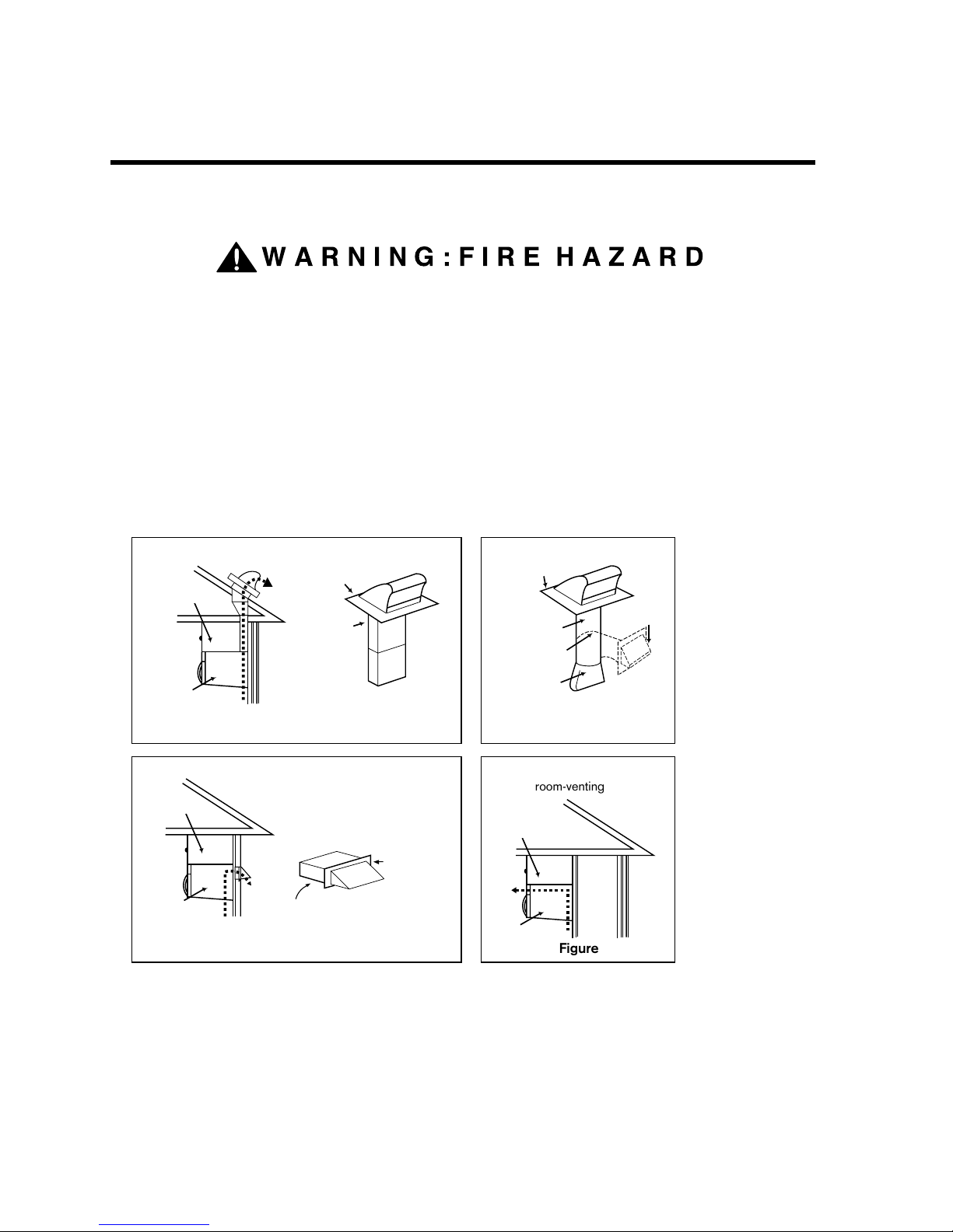
THIS OVEN MUST BE PROPERLY VENTED!
You may vent your oven in one of three ways:
Roof-venting If your oven is located on an outside wall near the roof, as in Figures 5 (31/4" x 10" duct)
and 6 (6" round duct.)
Wall-venting If your oven is located on an outside wall on the first floor of your house, as in Figure 7
(31/4" x 10" duct) and Figure 6 (6" round duct.)
Room-venting If your oven is located on an inside wall of your house, as in Figure 8.
REMEMBER AS YOU INSTALL THE VENTING:
• Keep the length of the ductwork and the number of elbows to a minimum to ventilate your oven efficiently.
See examples on page 9.
• Keep the size of the ductwork the same.
• Do not install two elbows together.
• Use duct tape to seal all joints in the duct system.
• Use caulking to seal the exterior wall or roof opening around the cap.
STEP 2:
PREPARE THE VENTING SYSTEM
Wall-venting
through-the-wall
wall cap
3 1/4"x10"
duct
Figure 7
cabinet
oven
through-the-roof
3 1/4"x10"
duct
Figure 5
roof cap
Roof-venting
cabinet
oven
6" min.
diameter
round duct
3 1/4" to round
duct transition
3 1/4" to round
ductwork transition
Figure 6
roof cap
wall cap
elbow
WARNING:FIRE HAZARD
room-venting
Figure 8
cabinet
oven
NOTE: The ductwork you need for outside ventilation is not included with your oven. The standard ductwork
fittings and length are shown in Figure 9, page 9.
NOTE: If you choose the rear exhaust method (roof- or wall-venting), be sure there is enough clearance within the
wall for the exhaust duct.
“wall-venting”
“roof-venting”
9
STEP 2:
PREPARE THE VENTING SYSYTEM
STANDARD FITTINGS
DUCT LENGTH
The total length of the duct system, including straight duct, elbows, transitions, wall or roof caps must not
exceed the equivalent of 140 feet.
For best performance, do not use more than three 90 degree elbows.
Below are the standard fittings and their equivalent length in feet.
Figure 9
Examples
For 3 1/4"x10" SYSTEMS
1-3 1/4" x 10" 90
o
elbow
1-Wall Cap
8 feet straight duct
TOTAL LENGTH
1-transition
2-90
o
elbows
1-Wall Cap
8 feet straight
TOTAL LENGTH
For 6" ROUND SYSTEMS
1
4567
23
3 1/4"x10"
to 6"=5ft.
90o elbow
=10ft.
45o elbow
=5ft.
3 1/4"x10"
wall cap
=40ft.
3 1/4"x10"
flat elbow
=10ft.
3 1/4"x10" roof
cap=24ft.
3 1/4"x10" 90˚
elbow=25ft.
6ft.
2ft.
2ft.
3 1/4"x10"
90o elbow
wall cap
6ft.
90
o
elbows
transition
wall cap
= 25 ft.
= 40 ft.
= 8 ft.
= 73 ft.
= 5 ft.
= 20 ft.
= 40 ft.
= 8 ft.
= 73 ft.
NOTE: If the existing duct is round, you must use a rectangular-to-round adapter, with a rectangular 3" extension
duct installed between the damper assembly and the adapter to prevent the exhaust damper’s sticking.
To calculate the equivalent length of each ductpiece used, see the examples below.
10
Your microwave oven is shipped with the blower assembled for roof venting. You need to adjust the blower if
you want wall-venting or room-vented (recirculating) installation.
ELECTRICAL SHOCK HAZARD! UNPLUG UNIT BEFORE WORKING ON IT.
• DO NOT PULL OR STRETCH THE BLOWER WIRING! Pulling and stretching the blower wiring could result in
electrical shock.
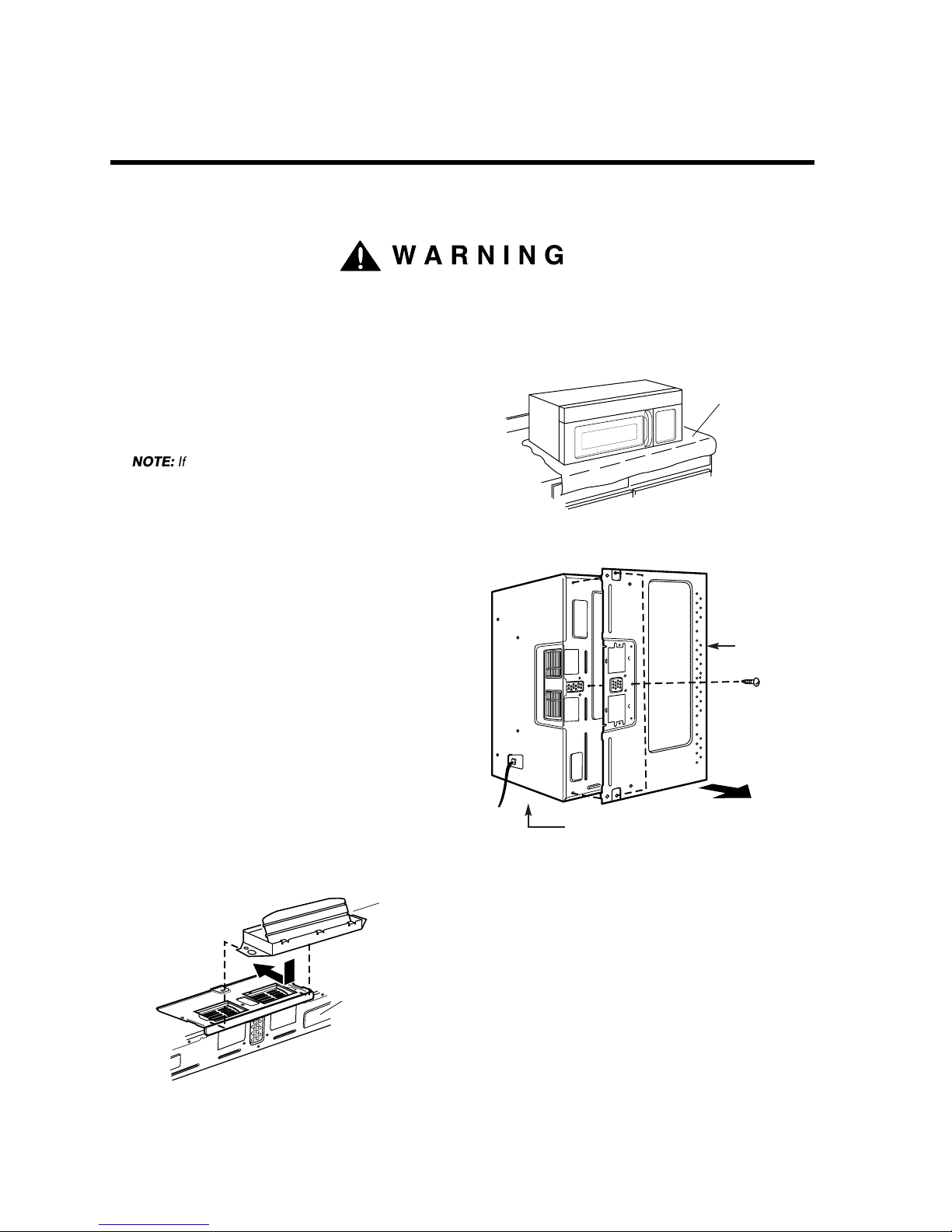
REMOVE THE MOUNTING PLATE:
1. Remove any shipping materials and parts from inside
the microwave oven.
2. Cover the countertop or cooktop with a thick,
protective covering to protect it from damage and dirt.
See Figure 10.
3. Remove mounting plate screw(s) (1 or 2 screws)
from the mounting plate as shown and discard
(see Figure 11).
4. This plate will be used to locate and mark the mounting
holes on the rear wall. (It will be used to locate and
mark the mounting holes on the rear wall.)
5. Locate exhaust adaptor, grease filters and hardware
packet.
6. At this point, remove any adhesive tape (if there is any),
on the exhaust adaptor, the grease filters and the
power supply cord.
ROOF-VENTED INSTALLATION:
This oven is shipped assembled for roof-vented. You
will need to install the exhaust adaptor regardless of
cabinet.
1. Attach the exhaust adaptor to the blower plate by
sliding it into the guides (see Figure 12).
Go to step 4 on page 13.
STEP 3:
PREPARE THE VENTING BLOWER
Figure 10
A thick, protective
covering
Figure 11
Mounting
plate
Mounting plate
screw(s)
(1 or 2 screws)
Control panel side
Figure 12
Back
of oven
Exhaust
adaptor
WARNING
NOTE: If you have a free-standing range, disconnect it, move it
onto a piece of cardboard or hardboard and pull it away
from the wall, so that you can get closer to the upper
cabinet and back wall for easier measuring and drilling.
11
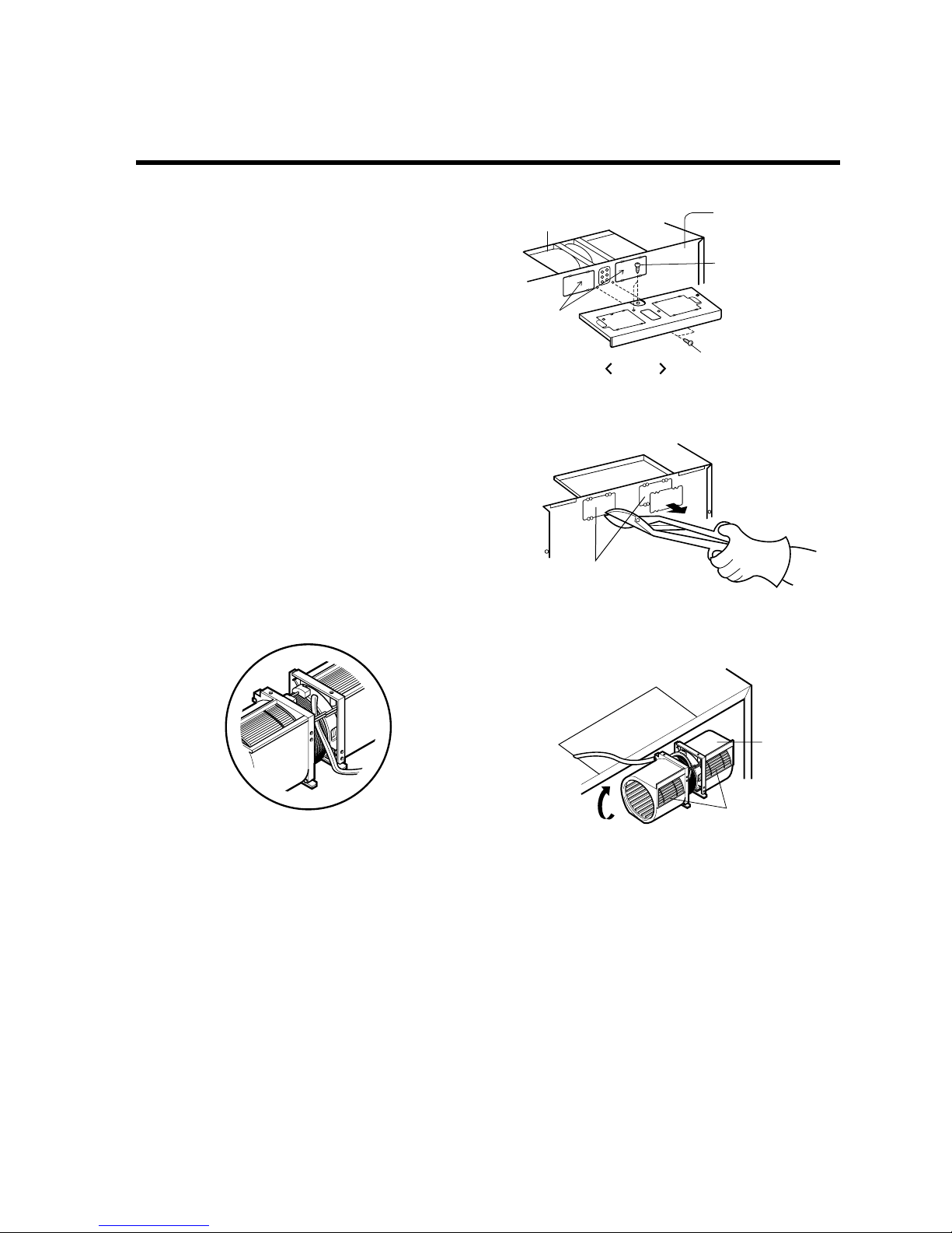
WALL-VENTED INSTALLATION:
1. Remove one blower unit mounting screw and one blower
plate screw. Remove the blower plate from cabinet.
See Figure 13.
2. Carefully lift the blower unit out of the microwave oven.
3. Use side cutters or tin snips to cut and remove knockouts
“B” from Back plate. Discard knockouts. Be careful not
to distort the plate. See Figure 14.
4. Reassemble the blower wire. See Figure 15.
5. Rotate the unit so that the exhaust ports face the rear of
the cabinet. See Figure 16. When you insert blower unit,
blower wire must be like Figure 16.
6. Place blower unit back into cabinet. Check that the
exhaust ports face towards the rear of the cabinet.
See Figure 17.
7. Reattach the blower plate to cabinet so the exhaust ports
and blower plate opening are aligned. Attach with one
blower unit mounting screw and then one blower plate
mounting screw. See Figure 18.
STEP 3:
PREPARE THE VENTING BLOWER
Figure 13
Option
blower plate
mounting screws
blower unit
mounting screw
blower unit
Parts "B"
back plate
Figure 14
Knockout Parts "B"
Parts "B"
Figure 16
exhaust
ports
blower
unit
Figure 15
 Loading...