

Page 1
삼 흥
정 판
Over-the-Range Microwave
Installation Instructions
For Models: HMV8050
PLEASE READ ENTIRE INSTRUCTIONS BEFORE PROCEEDING
IMPORTANT: Save these instructions for the local electrical inspector’s use.
INSTALLER: Please leave these Installation Instructions with this unit for the owner.
OWNER: Please retain these instructions for future reference.
Printed in Korea
P/No.: MFL06206602
Household Appliances
Page 2
YOUR SAFETY FIRST
BEFORE YOU START
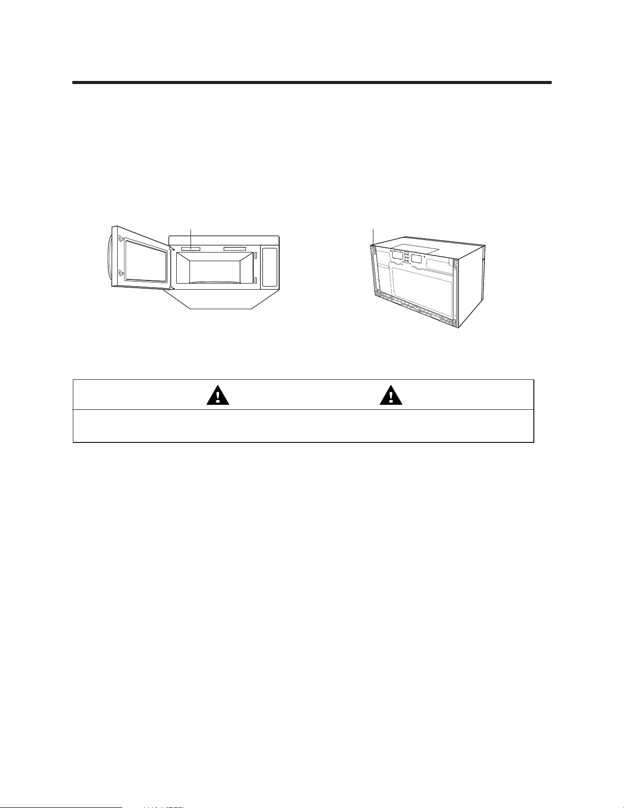
• Proper installation is the installer's responsibility!
– Read the entire manual before you begin. The Model number label is located on the oven front.
See Figure 1. Mounting plate is located on back side of microwave oven. See Figure 2.
BE SURE TO READ THE FOLLOWING SAFETY INSTRUCTIONS:
Model Number Plate
Figure 1 Figure 2
Mounting Plate
WARNING
For Your Safety
• You will need TWO people to install this oven. It is heavy and could cause personal injury if not handled
properly.
•
Avoid Electrical Shock!
– Before you drill into the wall, note where electrical outlets are and where electrical wires might be behind
concealed in the wall, YOU COULD GET AN ELECTRIC SHOCK if you contact electrical wires with your
drill bit.
– Locate and disconnect the power of any electrical circuits that could be affected by installing this oven.
IF YOU DO NOT DISCONNECT THE POWER, YOU COULD GET AN ELECTRIC SHOCK.
• ELECTRICAL RATING OF THIS OVEN : 120V AC. 60Hz.
– You need a 120V, 60Hz, AC only, 15A or 20A, fused electrical supply (located in the cabinet above the
microwave as close as possible to the microwave circuit) serving only the microwave.
– 2 –
Page 3
YOUR SAFETY FIRST
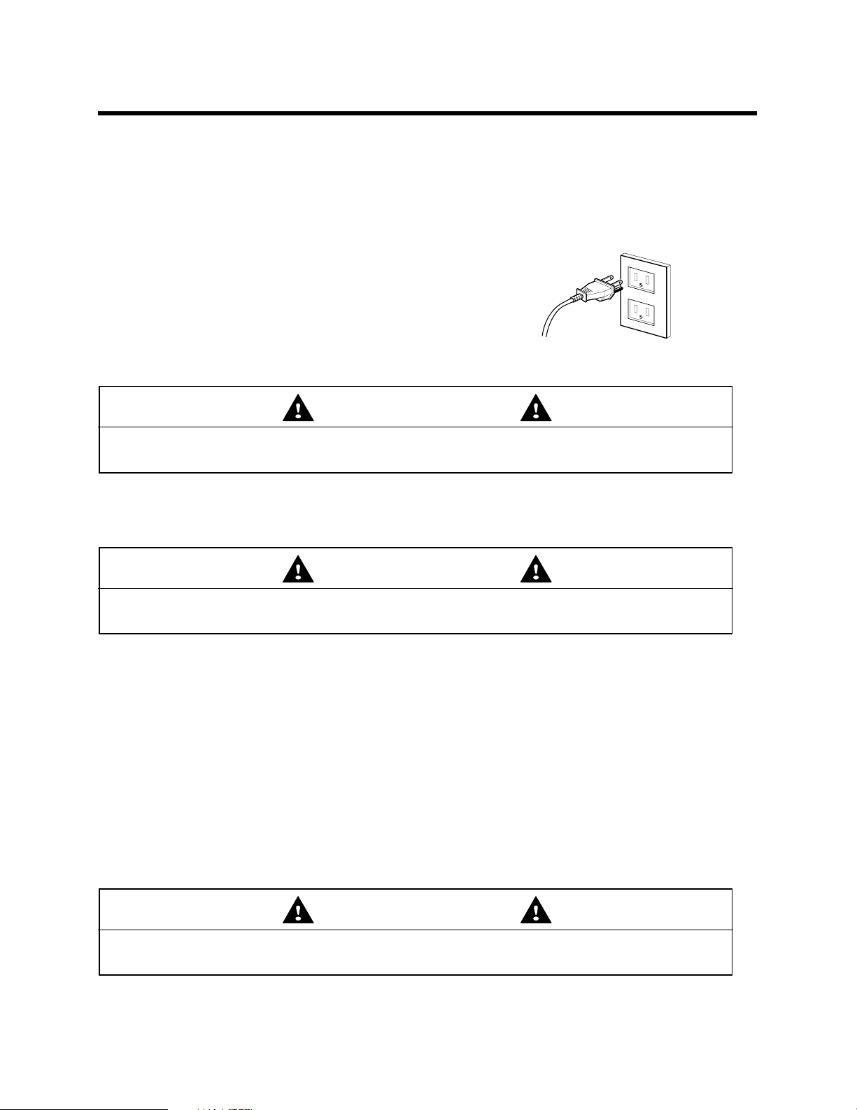
• THIS APPLIANCE MUST BE GROUNDED!
– If there is an electrical short circuit, grounding reduces the risk of electrical shock by providing an escape
wire for the electric current. This appliance is equipped with a cord having a grounding wire with a grounding
plug.
• Place the plug into a properly installed and grounded outlet. See Figure 3.
• Do not use an extension cord.
• Keep the power cord dry and do not pinch or crush it.
• DO NOT, UNDER ANY CIRCUMSTANCES, REMOVE THE
POWER SUPPLY CORD GROUNDING PRONG!
This appliance MUST be grounded!
WARNING
If you use the grounding plug improperly, you risk electric shock and or fire!
Check with a qualified electrician if you are not sure whether the oven is properly grounded or if you do not
completely understand the grounding instructions.
DO NOT USE A FUSE IN THE NEUTRAL OR GROUNDING CIRCUIT.
PROPERLY POLARIZED AND
GROUNDED OUTLET
Three-Pronged (Grounding) Plug
Figure 3
WARNING
Improper grounding could result in electric shock, fire or other personal injury.
SAVE THESE INSTRUCTIONS FOR THE LOCAL ELECTRICAL INSPECTOR'S USE.
• DO NOT EXPOSE YOURSELF TO EXCESSIVE MICROWAVE ENERGY!
– DO NOT try to operate the microwave oven with the door open.
– DO NOT tamper with or defeat the safety interlocks.
– DO NOT place objects between the microwave oven front face and the door.
– DO NOT allow soil or cleaner residue to build up on the flat surfaces around the microwave oven door.
– DO NOT operate the microwave oven if it is damaged.
– The microwave oven door must close properly to operate safely.
– DO NOT USE THE MICROWAVE OVEN:
• If the door is bent.
• If the hinges or latches are broken or loose.
• If the door seals, sealing surfaces or glass is broken.
– DO NOT ATTEMPT TO ADJUST OR REPAIR THE OVEN YOURSELF!
It should be adjusted and repaired by a qualified technician who can check for microwave leakage after
repairing the oven.
WARNING
If you do not use the microwave oven as instructed,
you could be exposed to excessive microwave energy.
– 3 –
Page 4
YOUR SAFETY FIRST
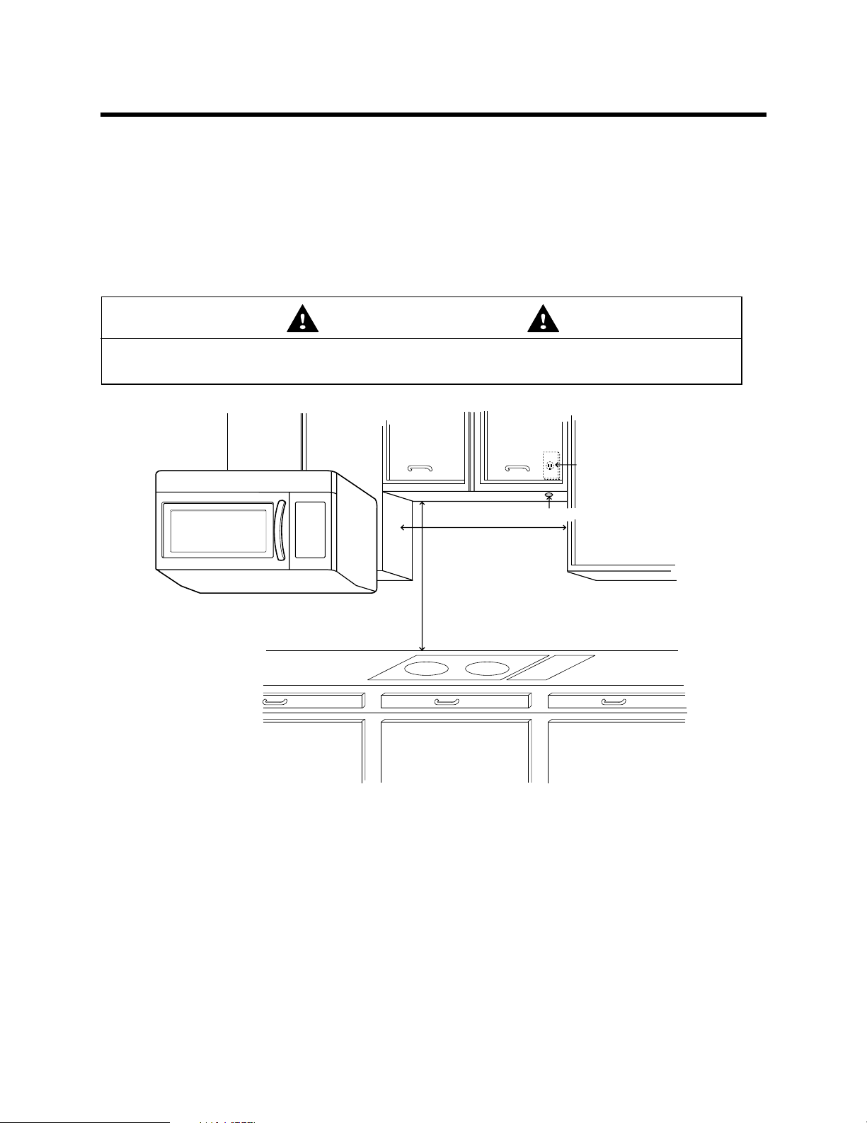
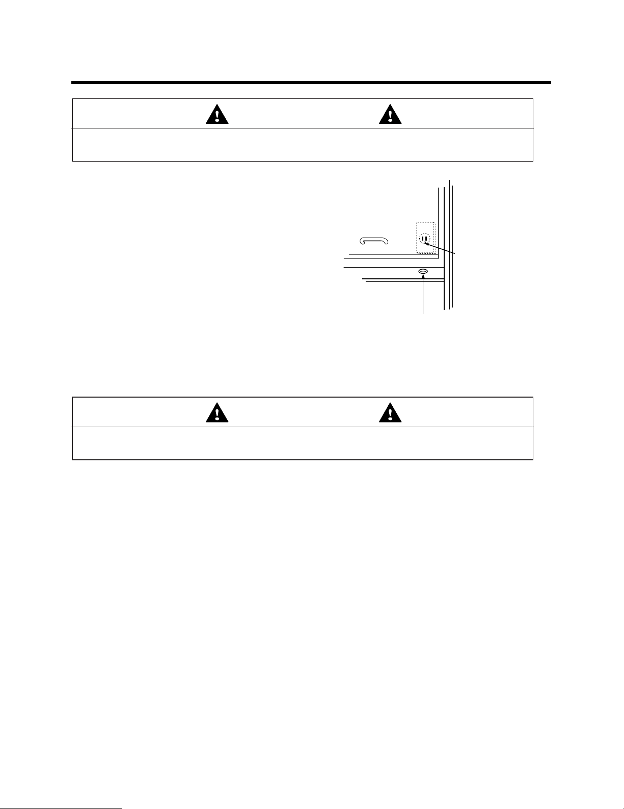
30" min. cabinet opening width
30" min. clearance from bottom
of cabinet to cooking surface
or countertop before installation.
Grounded Outlet
(inside upper cabinet)
Power Supply Cord Hole
(Use templates included
with installation instructions)
• MAKE SURE YOU HAVE ENOUGH SPACE AND SUPPORT.
– Mount the oven against a flat, vertical wall, so that it is supported by the wall. The wall should be
constructed of minimum 2" x 4" wood studding and 3/8" thick drywall or plaster/lath.
– ATTACH AT LEAST ONE of the two lag screws supporting the oven to a vertical, 2" x 4" wall stud.
– DO NOT mount the microwave oven to an island or peninsula cabinet.
– BE SURE the upper cabinet and rear wall structures are able to support 150 lbs., plus the weight of any
items you place inside the oven or upper cabinet.
– Locate the oven away from strong draft areas, such as windows, doors, and strong heating vents.
– BE SURE you have enough space. See Figure 4 below for minimum vertical and horizontal clearance.
WARNING
If you do not mount the oven as instructed,
you risk personal injury and/or property damage.
Figure 4
CAUTION
• Before you begin installing the oven, PLACE A PIECE OF THE CARTON OR OTHER HEAVY
MATERIAL (a blanket) over the countertop or cooktop to protect it. Do not use a plastic cover.
Failure to protect these surfaces could result in property damage.
– 4 –
Page 5
PARTS, TOOLS, MATERIALS
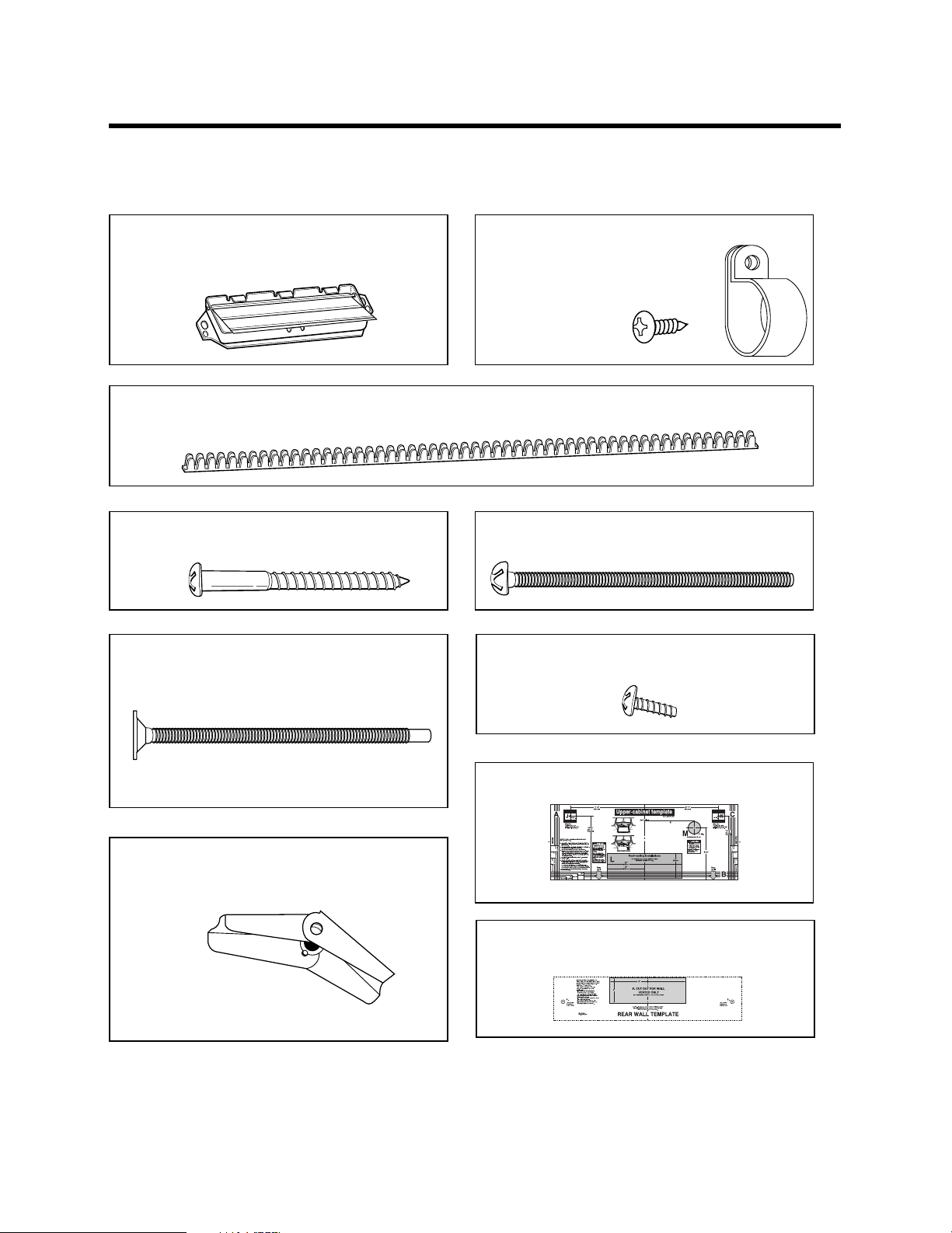
THE FOLLOWING PARTS ARE SUPPLIED WITH THE OVEN:
NOTE: Depending on your ventilation requirements, you may not use all of these parts.
Damper/duct connector
(for roof venting or wall venting installation)
Not Actual Size (2 pieces must be assembled as
shown)
One power cord clamp bushing - Actual Size (for the cord hole in a metal upper cabinet)
Four 1/4" x 2" lag screws - Actual Size
(for wall stud holes)
Two 1/4" x 3" bolts - Actual Size
(for securing to the upper cabinet)
One power cord clamp and
One dark-colored mounting screw
(to hold the power cord)
Actual Size
Four 1/4" x 3" toggle bolts - Actual Size
(for drywall holes)
Two tapping screws - Actual Size
(for attaching the damper duct connector)
One upper cabinet template- Not Actual Size
Four spring toggle heads - Actual Size
(for the toggle bolts)
One rear wall template- Not Actual Size
(3 pieces mounting plate only)
NOTE: You need to install at least two lag screws into a 2" x 4" stud and four anchor bolts into the wall.
and the mounting area must meet the 150 lbs. weight requirement.
– 5 –
Page 6
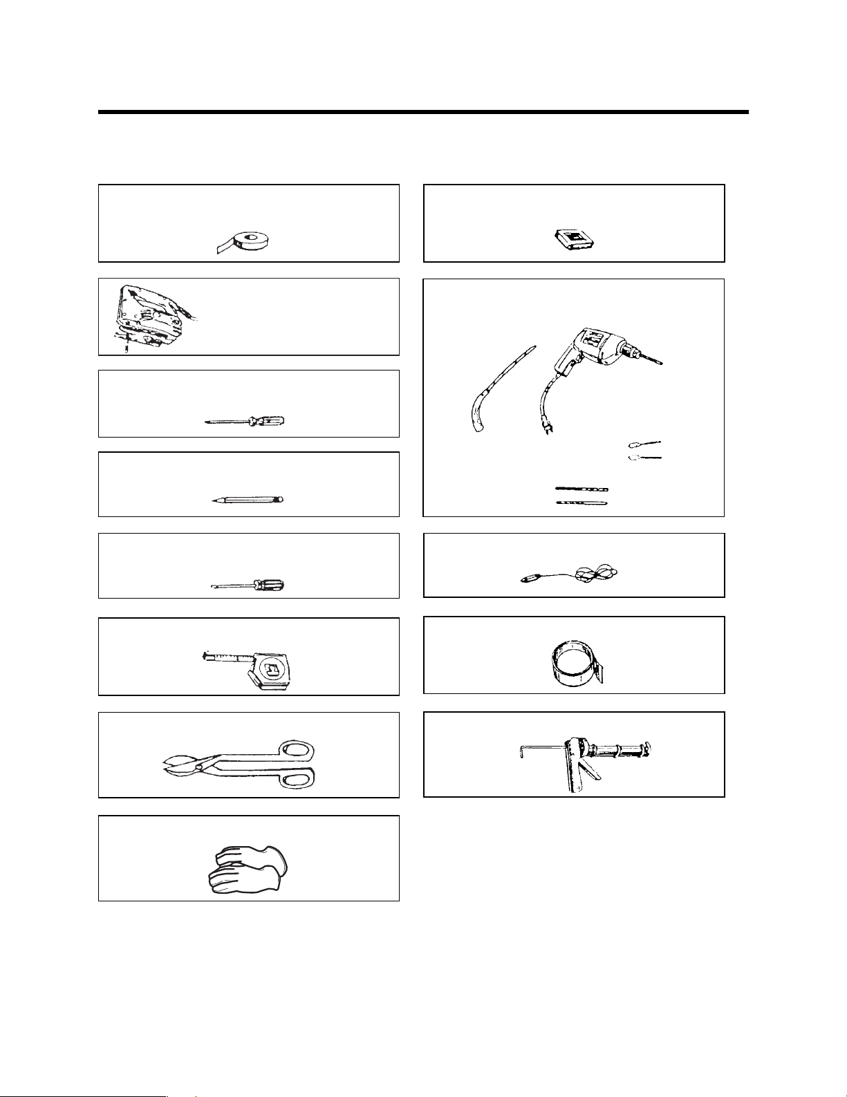
PARTS, TOOLS, MATERIALS
You will need the following tools and materials for the installation:
Carton or other heavy material for covering the counter top.
(for taping the templates to the wall)
Clear Tape
Saber Saw
(for cutting vent holes for roof
or wall vending)
Phillips Screwdriver
(for the screws)
Pencil
Flat Blade Screwdriver
(for the toggle bolts)
Stud Finder or Thin Nail
Keyhole Saw (for the power cord hole)
Electric Drill
3/8" and 3/4" wood drill bits
1/2" and 3/16"
drill bits
Plumb Line
Measuring Tape
(metal preferred)
Small Side Cutters or Tin Snips
Gloves
●
If you have brick or masonry walls, you will need special hardware and tools.
●
The ductwork you need for the installation is not included. All wall and roof caps must have a back-draft damper.
(Shown on page 5).
– 6 –
Duct Tape
Caulking Gun
Page 7
STEP 1: PREPARE THE ELECTRICAL
CONNECTIONS
WARNING
AVOID ELECTRICAL SHOCK! THIS APPLIANCE MUST BE GROUNDED!
1. Locate the grounded electric outlet for this oven in the
cabinet above the oven, as shown in Figure 5.
NOTE: The outlet should be on a circuit dedicated to the
microwave oven (120V, 60 Hz., AC only) with a 15 or 20A
fused electrical supply.
IMPORTANT: If you do not have the proper wall outlet,
you MUST have one installed by a qualified electrician.
2. You will cut the power-supply-cord hole (shown in Figure 5)
later when you prepare the wall and upper cabinet in Step 4.
Upper
Cabinet
Grounded Outlet
(Inside Cabinet)
NOTE: Do not use an extension cord.
Keep the power cord dry and do not pinch or crush it.
Power-Supply-Cord Hole
Figure 5
WARNING
Improper grounding could result in electric shock or other personal injury.
DO NOT, UNDER ANY CIRCUMSTANCES, REMOVE THE POWER SUPPLY CORD
GROUNDING PRONG!
This appliance MUST be grounded!
– 7 –
Page 8
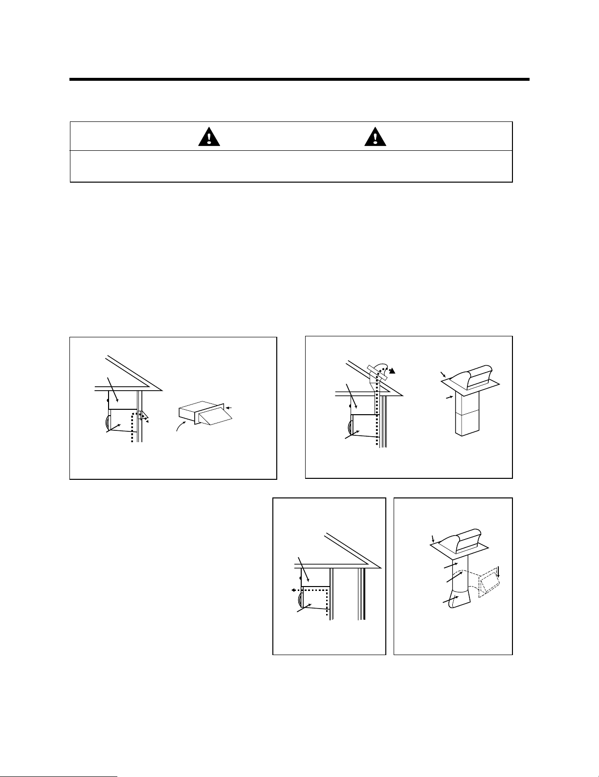
STEP 2: PREPARE THE VENTING SYSTEM
cabinet
oven
NOTE: The ductwork you need for outside ventilation is not included with your oven. The standard ductwork
fittings and length are shown in Figure 10, page 9.
WARNING
THIS OVEN MUST BE PROPERLY VENTED!
You may vent your oven in one of three ways. However, do NOT vent into a wall cavity, an attic, or an unused
area.
Roof-venting If your oven is located on an outside wall near the roof, as in Figures 7 (3 1/4" x 10" duct) and
Wall-venting If your oven is located on an outside wall of your house, as in Figure 6 (3 1/4" x 10" duct) and
Room-venting If your oven is located on an inside wall of your house, as in Figure 8.
NOTE: If you choose the rear exhaust method (roof-or wall-venting), be sure there is enough clearance within the
wall for the exhaust duct.
cabinet
Figure 9 (6" round duct.)
Figure 9 (6" round duct.)
Wall Venting
Roof Venting
roof cap
cabinet
wall cap
oven
Wall venting
3 1/4"x10"
duct
through-the-wall
Figure 6
REMEMBER AS YOU INSTALL THE
VENTING:
Keep the length of the ductwork and the
numberof elbows to a minimum to ventilate
your oven efficiently. See examples on page 9.
Keep the size of the ductwork the same.
Do not install two elbows together.
Use duct tape to seal all joints in the duct
system.
Use caulking to seal the exterior wall or roof
opening around the cap.
3 1/4"x10"
duct
oven
Roof venting
through-the-roof
Figure 7
Room Venting
roof cap
6"min diameter
round duct
elbow
3 1/4" to round
duct transition
ductwork transition
Figure 8 Figure 9
wall cap
3 1/4" to round
– 8 –
Page 9
STEP 2: PREPARE THE VENTING SYSTEM
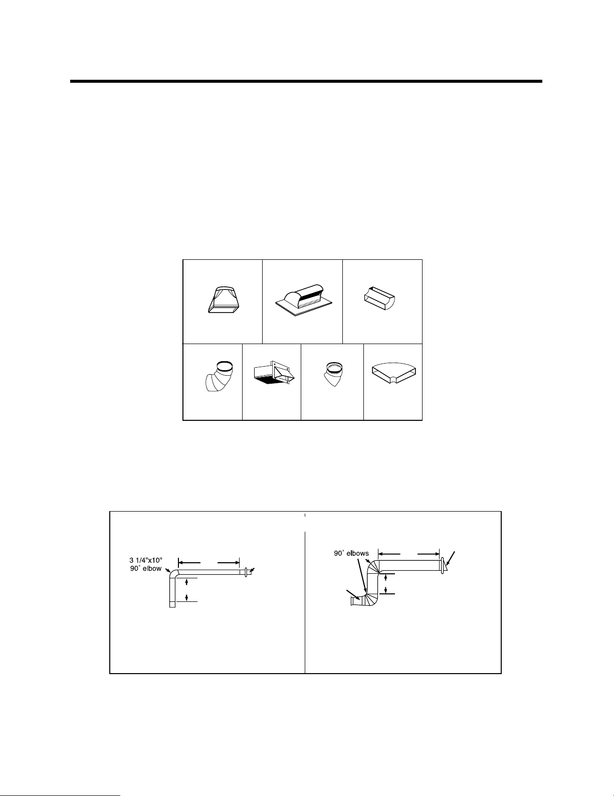
Standard Fittings
NOTE: If the existing duct is round, you must use a rectangular-to-round adapter, with a rectangular 3" extension
duct installed between the damper assembly and the adapter to prevent the exhaust damper’s sticking.
Duct Length
The total length of the duct system, including straight duct, elbows, transitions, and wall or roof caps must not
exceed the equivalent of 140 feet.
For best performance, do not use more than three 90 degree elbows, and keep length as short as possible.
Below are the standard fittings and their equivalent length in feet.
1 2 3
3 1/4” x 10”
to 6"=5ft.
4 5 6 7
90˚elbow
=10ft.
3 1/4” x 10” roof
3 1/4” x 10”
wall cap
=40ft.
cap=24ft.
45˚elbow
=5ft.
3 1/4” x 10” 90˚
elbow=25ft.
3 1/4” x 10”
flat elbow
=10ft.
Figure 10
To calculate the equivalent length of each duct piece used, see the examples below.
Examples
For 3 1/4"x10" SYSTEMS
6ft.
2ft.
wall cap
For 6"ROUND SYSTEMS
6ft.
transition
2ft.
wall cap
1-3 1/4” x 10” 90° elbow = 25 ft.
1-Wall Cap = 40 ft.
8 feet straight duct = 8 ft.
TOTAL LENGTH = 73 ft.
1-transition = 5 ft.
2-90° elbows = 20 ft.
1-Wall Cap = 40 ft.
8 feet straight = 8 ft.
TOTAL LENGTH = 73 ft.
– 9 –
Page 10
STEP 3: PREPARE THE VENTING BLOWER
WARNING
●
To avoid risk of property damage, unplug the microwave oven or disconnect power at
source by removing fuse or throwing circuit breaker.
●
To avoid risk of personal injury, wear protective gloves when handling mounting plate.
DO NOT PULL OR STRETCH THE BLOWER WIRING! Pulling and stretching the blower wiring could result in
electrical shock.
●
Your microwave oven is shipped with the blower assembled for room venting. If you want wall-venting
or roof-vented installation, you must change the blower, as detailed below.
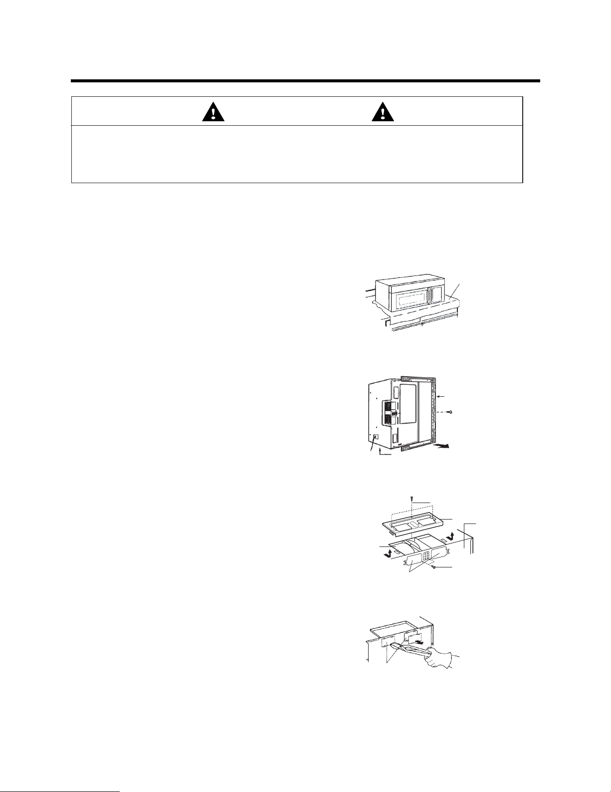
A thick, protective
Before You Start
1. Remove any shipping materials and parts from inside the
microwave oven.
2. Cover the counter top or cooktop with a thick, protective
covering to protect it from damage and dirt. See Figure 11.
NOTE: If you have a free-standing range, disconnect it, move it
onto a piece of cardboard or hardboard and pull it away
from the wall, so that you can get closer to the upper
cabinet and back wall for easier measuring and drilling.
Figure 11
covering
Remove The Mounting Plate:
1. Remove mounting plate screw(s) (1 or 2 screws) from the
mounting plate as shown and discard. See Figure 12.
2. This plate will be used as the rear mounting plate. (It will be
used to locate and mark the mounting holes on the rear wall.)
3. Locate exhaust adapter, grease filters and hardware packet.
4. At this point, remove any adhesive tape (if there is any), on the
exhaust adapter, the grease filters and the power supply cord.
Room-Vented (recirculating) Installation:
This oven is shipped assembled for room-vented.
Go to step 4 on page 12.
Wall-Vented Installation:
1. Remove one blower unit mounting screw and one or two
blower plate screw(s). Remove the blower plate from cabinet.
See Figure 13.
2. Carefully lift the blower unit out of the microwave oven.
3. Use side cutters or thin snips to cut and remove knockouts “B”
from Back plate. Discard knockouts. Be careful not to distort
the plate. See Figure 14.
Blower Unit
Control Panel Side
Parts “B”
Parts “B”
Mounting plate
Mounting plate
screw(s)
(1 or 2 screws)
Figure 12
Blower Plate
Mounting Screw (option)
Figure 13
Knockouts Parts “B”
Blower Plate
Back Plate
Blower Unit
Mounting Screw (option)
– 10 –
Figure 14
Page 11
STEP 3: PREPARE THE VENTING BLOWER
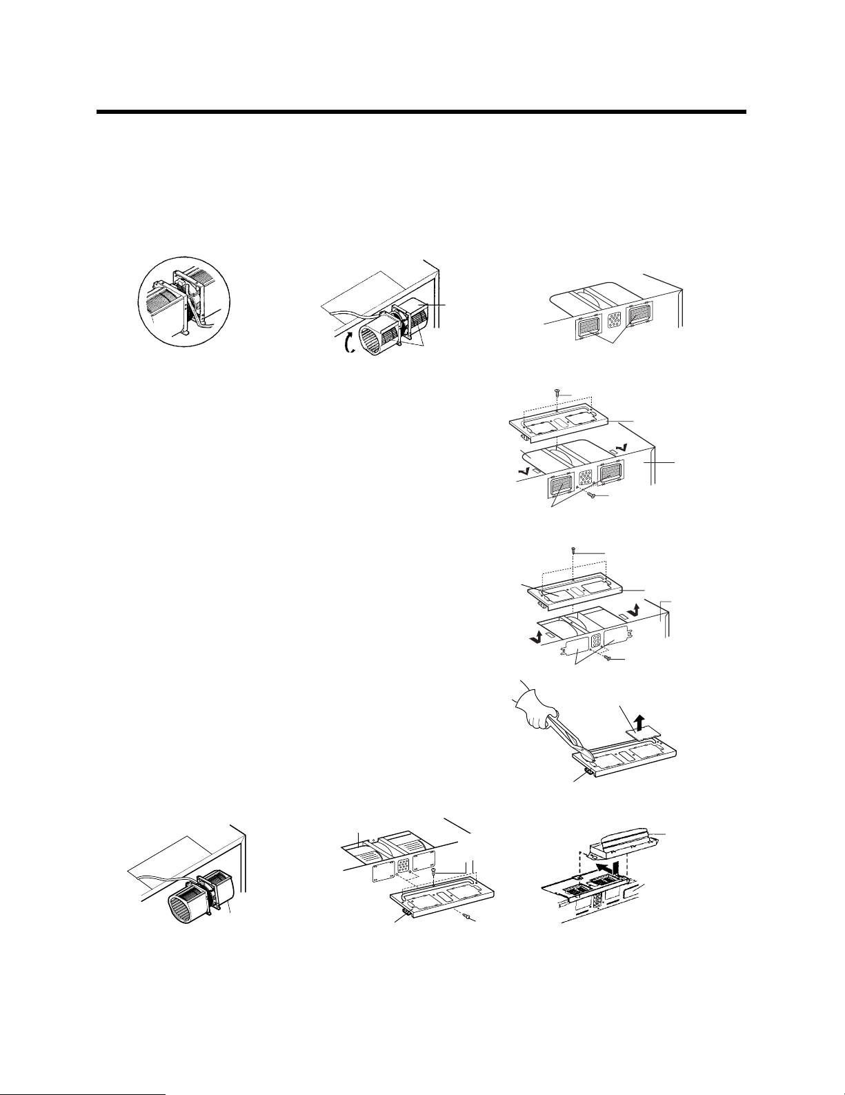
4. Reassemble the blower wire. See Figure 15.
5. Rotate the unit so that the exhaust ports face the rear of the cabinet. See Figure 17. When you insert blower unit,
blower wire must be like figure 16.
6. Place blower unit back into cabinet. Check that the exhaust ports face towards the rear of the cabinet. See Figure
17.
7. Reattach the blower plate to cabinet so the exhaust ports and blower plate opening are aligned. Attach with one
blower unit mounting screw and then one blower plate mounting screw. See Figure 18.
blower
unit
exhaust
Figure 15
Roof-Vented Installation:
ports
Figure 16
exhaust
ports
blower plate
mounting screw (option)
Figure 17
1. Remove one blower unit mounting screw and one or two
blower plate screw(s). Remove the blower plate from cabinet.
See Figure 19.
2. Use side cutter or thin snips to cut and remove knockouts "A"
from Blower plate. Discard knockouts. Be careful not to distort
the plate. See Figure 20.
3. Carefully lift the blower unit out of the microwave oven.
4. Rotate blower unit 90° so the exhaust ports face the top of
the cabinet. See Figure 21.
5. Reassemble the blower wire.
6. Place blower unit back into microwave oven.
7. Reattach blower plate to microwave oven. Attach with the one
blower unit mounting screw and then the one or two blower
plate mounting screw(s). See Figure 22.
8. Attach the exhaust adapter to the blower plate by sliding it into
the Guide. See Figure 23.
blower unit
blower unit
blower unit
exhaust ports
blower unit
parts “B”
blower plate
blower plate
mounting screw (option)
Figure 18
Figure 19
Knockouts “A”
Figure 20
blower plate
back plate
blower unit
mounting screw (option)
blower plate
mounting screw (option)
blower plate
back plate
blower unit
mounting screw (option)
Exhaust
adapter
blower
unit
blower plate
blower unit
mounting screw
(option)
Figure 21 Figure 22 Figure 23
– 11 –
Back
of oven
Page 12

STEP 4: PREPARE THE WALL & UPPER
CABINET
WARNING
To avoid personal injury or property damage, do not attempt to install this microwave
oven if you cannot find a wall stud.
Measure And Track/Tape Up The Templates
1. Using a plumb line and (metal) measuring tape, find and mark
the vertical center line on the back wall, as in Figure 24.
2. Find and mark one or two points where the studs are on the
wall. (Studs are normally 16 inches apart). Then measure and
mark the stud locations. If you cannot find any wall stud,
consult a local building contractor.
CAUTION
DO NOT ATTEMPT TO INSTALL THE MICROWAVE OVEN IF YOU CANNOT FIND A WALL
STUD.
3. Line up the plumb line on the wall with the center line on the
mounting plate.
NOTE: Be sure the minimum width is 30 inches and the distance
from the top of the wall template to the range or counter
top is at least 30 inches. See Figure 24.
4. Center mounting plate in operating by lining up the plumb line
on wall with centerline on mounting plate. Make sure the
minimum width is 30 inches and that the top of the mounting
plate is located a minimum of 30 inches above the cooking
surface. See Figure 25.
NOTE: If the cabinets are not plumb, adjust the mounting plate to
the cabinets. If the front edge of the cabinet is lower than
the back edge, adjust the mounting plate to be level with
the cabinet front.
5. Measure the bottom of the upper cabinet frame. Trim the edges
A, B and C on the upper cabinet template so that the template
will fit on the bottom of the upper cabinet. If upper cabinet has
a recessed frame, trim the template so it fits inside the
recessed area. Align the centerline of the upper cabinet
template with the centerline of the mounting plate, then
securely tape or tack the upper cabinet template in place. See
Figure 25.
Figure 24
upper cabinet template
mounting plate
(3 pieces mounting plate)
Figure 25
– 12 –
Page 13

STEP 4: PREPARE THE WALL & UPPER
CABINET
WARNING
To avoid risk of personal injury, electrical shock or death:
Note where electrical outlets and electrical wires are before you drill into the wall.
Locate and disconnect power to any electrical circuits that could be affected by
installing this oven.
WARNING
To avoid risk of personal injury, electrical shock or death, cover the edge of the power
supply cord hole with the power supply cord bushing.
Drill The Holes In The Wall And Upper Cabinet.
1. Drill holes on the circles. If there is a stud, drill a 3/16"hole for
lag screws. If there is no stud, drill a 3/4
screws. Make sure to use at least 1 lag screw in a stud, and 4
toggle screws in the drywall or the plaster.
2. Drill a 3/8” hole at points J and K on the upper cabinet
template.
NOTE: If the bottom of the upper cabinet is recessed 3/4
more, you will need 2
provide additional support for the bolts. See Figure 26.
Mark the center of each filler block and drill a 3/8”
diameter hole at the marks.
Align filler blocks over the two openings in the top of
the microwave oven cabinet and attach to cabinet with
masking tape. See Figure 27.
"
3. Cut or drill a 2
supply cord hole on the upper cabinet template. If the upper
cabinet is metal, you will need to cover the edge of the hole
with the power supply cord bushing (supplied) to prevent
damage to the cord from the rough metal edge.
4. Cut out the venting areas (with the saber saw):
Roof-Vented: cut out the shaded area marked L on the
upper cabinet template.
Wall-Vented: Tape the rear wall template to the rear wall,
lining up with the holes previously drilled for holes A and B
in the plate. Cut out the shaded area marked F on the REAR
WALL TEMPLATE.
Room-Vented: go to STEP 5, INSTALL THE MOUNTING
PLATE, located on page 14.
5. Complete whichever venting system you have chosen. Use
caulking compound to seal the exterior wall or roof opening
around the wall cap or roof cap.
diameter hole at the area marked M. Power
"
x 2"filler blocks (not included) to
"
hole for toggle
"
or
cabinet front
filler block
Figure 26
Figure 27
cabinet
bottom shelf
filler
block
– 13 –
Page 14

STEP 5: INSTALL THE MOUNTING PLATE
3/16?Hole on Studs
5/8?Hole on Dry wall Only
Center Line
Draw
Center Line
Draw Lines
on Studs
For Wall-
Vented Only
Minimum 66
"
From the Floor
Support Tab Support Tab
E
Mounting
Plate
C
D
A
B
(3 pieces mounting plate)
Wall
Mounting
Plate
Space More Than Wall Thickness
Bolt
End
Toggle Bolt
Toggle Wings
The Oven Must Be Connected To At Least One
Wall Stud.
1. Draw a vertical line on the wall at the center of the 30 wide
space. Use the mounting plate as the template for the rear
wall. Place the mounting plate on the wall, making sure
that the tabs are against the bottom of the cabinet. Line up
the notch and center line on the mounting plate to the
center line on the wall.
2. While holding the mounting plate with one hand, draw
circles on the wall at holes A, B, C and D. Four holes must
be used for mounting. If the holes are not used, the
installation will not be secure. Installer must use these
holes for proper installation. Use toggle bolts through these
holes unless one of them lines up with a stud. Use a wood
screw for studs.
NOTE: Draw a fifth circle inside area E, through one of the
3. Drill holes on the circles. If there is a stud, drill a 3/16 hole
4. Attach the plate to the wall. To use spring toggle head
bottom holes to match the location of a stud. For wallvented: The oven requires a rear wall cutout opening
for the rear wall duct and the exhaust adaptor must be
attached to the mounting plate. See the next page on
how to prepare the rear wall cutout opening and the
exhaust adapter/mounting plate for wall-vented.
for lag screws. If there is no stud, drill a 5/8 hole for toggle
bolts. Make sure to use at least 1 lag screw in a stud, and
4 toggle bolts in the drywall or the plaster.
Figure 28
bolts: Remove the toggle wings from the bolts. Insert the
bolts into the mounting plate and replace the spring toggle
head to 3/4 past the bolt ends. Insert the spring toggle
head into the holes in the wall to mount the plate. You may
pull forward on the plate to help in tightening the toggle
bolts. Tighten all bolts.
Figure 29
– 14 –
Page 15

STEP 5: INSTALL THE MOUNTING PLATE
For Wall-Vented
Make the box cutout for the rear wall duct.
– 3 pieces mounting plate:
Use the wall template to determine the location and size of
the box cutout for the rear wall duct.
Attach the exhaust adapter to the rear mounting plate (back
plate) wall side. Push in securely until it is past the top locking
tabs and in the lower locking tabs. Take care to assure the
damper hinge is installed so that it is at the top and that the
damper swings freely.
Carefully guide the exhaust adapter, now attached to the
mounting plate, into the house duct. Before using the screws to
attach the plate to the wall. This will assure proper alignment
for installation.
Return to step 5, item 3 to continue. After completing the
installation of the mounting plate, again check the rear damper
for free movement to assure it will operate properly.
Exhaust Adapter
Slide exhaust
adapter into
guides on
rear panel.
Locking
Tabs
Figure 30
Damper
(hinge side up)
Back Plate
(wall side)
Guides
– 15 –
Page 16

STEP 6: ATTACH THE OVEN TO THE WALL
WARNING
To avoid risk of personal injury or property damage, use will need two people to
install this microwave oven.
1. Carefully lift microwave oven and hang it on support tabs
(See Figure 28) at the bottom of the mounting
plate.Reaching through upper cabinet, thread
power supply cord through the power supply cord
hole in the bottom of the upper cabinet.
See Figure 31.
2. Rotate the microwave oven upward so the top of
oven is against the bottom of the upper cabinet or
cabinet frame.
3. Then insert a bolt down through each hole in the
upper cabinet bottom.See Figure 32.
Tighten the bolts until the gap between the upper cabinet
and microwave oven is closed.
power cord
power cord
hole
Figure 31
4. If wall vented or room vented installation is used,go to
No. 7 on the next page.
Figure 32
– 16 –
Page 17

STEP 6: ATTACH THE OVEN TO THE WALL
5. Roof venting installation: See Figure 33.
Install ductwork through the vent opening in the
upper cabinet. Complete the venting system through the
roof according to the method needed. See
Venting System
Use caulking gun to seal the exterior roof opening
around the exhaust cap. See Figure 7 on page 8.
6. Use the power supply cord clamp to bundle the power
supply cord. Install the power supply cord clamp, using a
screw as shown in Figure 34, to the inside of the cabinet.
7. Grasp filter screen with one hand holding the ring and
the other hand holding the opposite end. Insert the end
of the filter screen without ring into the opening and slide
towards the side of the microwave oven. Insert ring end
of filter screen into the opening and slide entire screen
towards the center of the microwave until screen is
securely in position. Repeat for other filter screen. See
Figure 35.
8. Plug in the power supply cord.
9. Read your Owner’s Manual, then check the operation of
your microwave oven.
"
STEP 2.
"
Prepare The
Figure 33
Figure 34
– 17 –
Figure 35
Page 18

Memo
Page 19

삼 흥
정 판
Électroménagers
Four à micro-ondes avec hotte
Instructions d’installation
For Models: HMV8050
PRIÈRE DE LIRE TOUTES LES INSTRUCTIONS AVANT DE PROCÉDER À L’INSTALLATION.
IMPORTANT : Conserver ces instructions pour que l’inspecteur local puisse vérifier l’installation.
INSTALLATEUR : Prière de remettre ces instructions au propriétaire après l’installation.
PROPRIÉTAIRE : Conserver ces instructions pour référence future.
Imprimé en Corée
Piéce n°: MFL06206602
Household Appliances
Page 20

VOTRE SÉCURITÉ AVANT TOUT
AVANT DE DÉBUTER
• Une installation adéquate est la responsabilité de l’installateur!
– Veuillez lire tout le manuel avant de débuter. L’étiquette du numéro de modèle est située à l’avant du four à micro-ondes.
Référez-vous au schéma 1. La plaque de montage est située à l’arrière du four. Référez-vous au schéma 2.
ASSUREZ-VOUS DE LIRE LES MESURES DE PRÉVENTION SUIVANTES :
Schéma 1 Schéma 2
AVERTISSEMENT
POUR VOTRE SÉCURITÉ:
•
DEUX personnes devront être présentes pour installer ce four. Il est lourd et pourrait vous blesser si
vous ne le manipulez pas adéquatement.
• Évitez les chocs électriques!
– Avant de percer dans le mur, remarquez l’emplacement des prises de courant ainsi que l’endroit où passent les fils
électriques. VOUS POURRIEZ VOUS ÉLECTROCUTER si vous touchez à des fils avec la mèche de votre perceuse.
– Localisez et coupez le courant de tous les circuits électriques qui pourraient être touchés lors de l’installation du four.
VOUS POURRIEZ VOUS ÉLECTROCUTER SI VOUS NE COUPEZ PAS LE COURANT.
• TENSION ASSIGNÉE À CE FOUR : 120V CA, 60Hz.
– Vous devez posséder une source d’alimentation avec fusibles (située dans l’armoire la plus proche que possible de la prise
du four) de 120V, 60Hz, CA seulement, de 15A ou 20A et qui est dédiée exclusivement au four à micro-ondes.
– 2 –
Page 21

VOTRE SÉCURITÉ AVANT TOUT
• VOUS DEVEZ EFFECTUER LA MISE À LA TERRE DE CET APPAREIL!
– S’il se produit un court-circuit, la mise à la terre réduit les risques de choc électrique en procurant une voie de sortie à
l’alimentation électrique. Cet appareil possède un cordon d’alimentation muni d’un fil et d’une fiche avec mise à la terre.
• Branchez la fiche dans une prise bien installée et mise à la terre. Référez-vous au schéma 3.
• Ne vous servez pas de cordon d’extension.
• Gardez le cordon au sec et sans le pincer ni l’écraser.
• NE COUPEZ JAMAIS LA BROCHE DE MISE À LA TERRE
DE VOTRE CORDON D’ALIMENTATION!
Cet appareil DOIT être mis à la terre!
AVERTISSEMENT
Vous risquez de vous électrocuter si vous n’utilisez pas adéquatement
la prise avec mise à la terre!
Consultez un électricien qualifié si vous doutez que votre four soit bien mis à la terre ou si vous ne comprenez pas
complètement les instructions de mise à la terre.
N’UTILISEZ PAS DE FUSIBLE DANS LE CIRCUIT NEUTRE OU DE MISE À LA TERRE.
PRISE DE COURANT POLARISÉE ET
ADÉQUATEMENT MISE À LA TERRE
Fiche à trois broches (avec prise de terre)
Schéma 3
AVERTISSEMENT
Une mauvaise mise à la terre pourrait occasionner un choc électrique ou
d’autres blessures.
CONSERVEZ CES INSTRUCTIONS EN CAS D’UNE VISITE PAR L’INSPECTEUR
EN BÂTIMENTS DE VOTRE QUARTIER.
• NE VOUS EXPOSEZ PAS À UN SURPLUS D’ÉNERGIE DU FOUR À MICRO-ONDES!
– NE TENTEZ PAS de faire fonctionner le four si la porte est ouverte.
– N’ESSAYEZ PAS d’altérer ni d’annuler les mécanismes d’enclenchement de sécurité.
– NE PLACEZ PAS d’objets entre la porte et la devanture du four.
– NE LAISSEZ PAS s’accumuler les résidus de saleté ou de détergents sur les surfaces plates autour de la porte du four.
– NE FAITES PAS FONCTIONNER le four s’il est endommagé.
– La porte du four doit pouvoir se refermer parfaitement afin que l’appareil fonctionne en toute sécurité.
– N’UTILISEZ PAS LE FOUR À MICRO-ONDES :
• Si la porte est tordue.
• Si les charnières ou loquets sont brisés ou lâches.
• Si les joints d’étanchéité de la porte ou de la vitre sont brisés.
– N’ESSAYEZ PAS D’AJUSTER NI DE RÉPARER LE FOUR PAR VOUS-MÊME!
Il ne doit être ajusté et réparé que par un technicien qui peut vérifier s’il n’y a pas de fuite de micro-ondes après avoir réparé
le four.
AVERTISSEMENT
Vous pourriez vous exposer à un surplus de micro-ondes si vous n’utilisez
pas le four à micro-ondes tel qu’indiqué.
– 3 –
Page 22

VOTRE SÉCURITÉ AVANT TOUT
• ASSUREZ-VOUS D’AVOIR SUFFISAMMENT D’ESPACE ET DE SOUTIEN.
– Montez le four sur un mur vertical et plat afin qu’il puisse être soutenu par le mur. Le mur devrait être monté sur des
madriers d’au moins 2 po. x 4 po. et fait de plâtre, lattes ou de feuilles de gypse d’une épaisseur minimale de 3/8 po.
– VISSEZ AU MOINS UNE des deux vis à tête ronde qui supportent le four à un madrier vertical de 2 po. x 4 po.
– N’INSTALLEZ PAS le four au-dessus d’un îlot central ni sous une armoire suspendue.
– ASSUREZ-VOUS que les structures de l’armoire et du mur arrière puissent soutenir un poids de 150 lbs en plus du poids
des items que vous placez dans le four et ceux qui se trouvent déjà dans les armoires supérieures.
– Éloignez le four des endroits où les courants d’air sont trop forts tels que les fenêtres, portes et bouches de chauffage
puissantes.
– ASSUREZ-VOUS de posséder suffisamment d’espace. Référez-vous au schéma 4 ci-dessous pour calculer l’espace de
dégagement minimal sur le plan vertical et horizontal.
AVERTISSEMENT
Vous risqueriez de vous blesser et/ou d’endommager vos biens si
vous n’installez pas le four selon les instructions.
Schéma 4
MISE EN GARDE
• Avant de débuter l’installation du four, PLACEZ UN MORCEAU DE CARTON OU DE TISSUS ÉPAIS (une couverture)
sur le comptoir ou sur votre four conventionnel afin de le protéger. N’utilisez pas de recouvrement de plastique.
Vous pourriez endommager vos biens si vous ne protégez pas adéquatement ces surfaces.
– 4 –
Page 23

PIÈCES, OUTILS, MATÉRIAUX
LES PIÈCES SUIVANTES SONT FOURNIES AVEC LE FOUR:
REMARQUE:Les pièces utilisées dépendent des besoins en ventilation ; elles ne sont pas nécessairement toutes
utilisées.
Clapet de refoulement / raccord de conduit
(pour les installations à évacuation par le toit ou le mur)
Taille non réelle (les 2 éléments doivent être assemblés
tel qu’indiqué)
Une traversée pour serre-câble - Grandeur réelle
(pour le trou de cordon dans une armoire supérieure en métal)
Quatre tire-fonds de 1/4 x 2 po(6 x 51 mm)-
Grandeur réelle
(pour les trous dans les montants du mur)
Deux boulons 1/4 x 3 po- Grandeur réelle
(pour attacher l'armoire supérieure)
Un serre-câble et
une vis de couleur foncée
(pour retenir le cordon d’alimentation)
Grandeur réelle
Quatre boulons à ailettes de 1/4 x 3 po(6 x 76 mm)-
Grandeur réelle
(pour les trous dans le placoplâtre)
Deux vis autotaraudeuses - Grandeur réelle
(pour attacher le raccord de conduit du clapet de
refoulement)
Plantilla de un gabinete superior -
No es de tamaño real
Quatre écrous à ailettes - Grandeur réelle
REMARQUE: Il faudra poser au moins deux tire-fonds dans un montant de 2 x 4 po (51 x 102 mm) et quatre boulons
(pour les boulons à ailettes)
Plantilla en la pared posterior - No es el tamaño real
(Placa de (3) tres piezas de montura solamente)
d’ancrage dans le mur. La partie portante doit satisfaire aux conditions de capacité de support de 150 lb (68
kg) minimum.
– 5 –
Page 24

PIÈCES, OUTILS, MATÉRIAUX
Il faut les outils et matériaux suivants :
Carton ou autre matériau épais pour couvrir le comptoir.
Ruban adhésif transparent
(pour maintenir les gabarits sur le mur)
Scie sauteuse
(pour découper les trous
d’évacuation dans le toit ou le mur)
Tournevis cruciforme
(pour les vis)
Crayon à papier
Tournevis à lame plate
(pour les boulons à ailettes)
Détecteur de clous ou clou mince
Scie à guichet (pour découper le trou du cordon
d’alimentation)
Perceuse
électrique
Forets à bois de 3/8 po et 3/4 po
Forets à bois de
1/2 po et3/16 po
Fil à plomb
Ruban à mesurer
(de préférence en métal)
Pince à coupe de côté ou ciseaux à métaux
Gants
●
Si le mur est en briques ou en maçonnerie, il faut de la visserie et des outils spéciaux.
●
Les conduits nécessaires pour l’évacuation ne sont pas inclus. Les capuchons muraux ou de toit doivent être
munis d’un clapet de refoulement. (Montré page 5.)
Ruban adhésif en toile
Pistolet à calfeutrer
– 6 –
Page 25

ÉTAPE 1 : PRÉPARER LE
RACCORDEMENT À L’ÉLECTRICITÉ
AVERTISSEMENT
ÉVITEZ LES RISQUES DE CHOC ÉLECTRIQUE!
CET APPAREIL DOIT ÊTRE MIS À LA TERRE!
1. Placer la prise de courant reliée à la terre dans laquelle sera
branché le four dans l’armoire au-dessus du four, tel
qu’indiqué à la schéma 5.
REMARQUE : La prise doit être raccordée à un circuit
réservé au four à micro-ondes (120 V, 60 Hz, courant
alternatif uniquement) et protégé par un fusible de 15
ou 20 A.
IMPORTANT: En cas d’absence d’une prise de courant
qui convienne, il FAUT en faire poser une par un électricien
qualifié.
2. Le trou pour le cordon électrique (montré à la schéma 5) sera
découpé plus tard, au moment de la préparation du mur et de
l’armoire supérieure, à l’étape 4.
REMARQUE : Ne pas utiliser de rallonge.
Garder le cordon d’alimentation au sec et ne
pas le pincer ni l’écraser.
Armoire
supérieure
Trou pour le cordon d’alimentation
Schéma 5
Prise reliée à la
terre
(dans l’armoire)
AVERTISSEMENT
Une mauvaise mise à la terre pourrait occasionner un choc
électrique ou des blessures graves.
LA BROCHE DE MISE À LA TERRE DU CORDON D’ALIMENTATION ÉLECTRIQUE
NE DOIT EN AUCUN CAS ÊTRE COUPÉE OU ENLEVÉE DE LA PRISE !
Cet appareil DOIT être relié à la terre !
– 7 –
Page 26

ÉTAPE 2 : PRÉPARER L’ÉVACUATION
REMARQUE : Les conduits nécessaires à l’évacuation vers l’extérieur ne sont pas fournis. Le matériel et les
longueurs de conduits standard sont indiqués à la schéma 10, page 9.
AVERTISSEMENT
CE FOUR DOIT ÊTRE RACCORDÉ À UNE ÉVACUATION APPROPRIÉE !
L’évacuation peut se faire de trois façons différentes. Toutefois, NE PAS faire déboucher l’évacuation dans une
cavité, un grenier ou un endroit non utilisé.
Évacuation par le toit Si le four est posé sur un mur donnant sur l’extérieur et à proximité d’un toit,
Évacuation par le mur Si le four est posé sur un mur donnant sur l’extérieur, comme l’illustrent les
Évacuation dans la pièce Si le four est posé sur une cloison intérieure, comme l’illustre la schéma 8.
REMARQUE : Dans le cas d’une évacuation par l’arrière (évacuation par le mur ou par le toit), vérifier qu’il y a
suffisamment de place dans le mur pour le conduit d’évacuation.
Évacuation par le mur
comme l’illustrent les schéma 7 (conduit de 3 1/4 x 10 po [8,2 x 25,4 cm]) et 9
(conduit de 6 po [15 cm] de diamètre).
schéma 6(conduit de 3 1/4 x 10 po [8,2 x 25,4 cm]) et 9 (conduit de 6 po
[15 cm] de diamètre).
Évacuation par le toit
armoire
four
par le mur
"
x10
3 1/4
conduit de
"
à travers le mur
Schéma 6
PENDANT LA POSE DU MATÉRIEL
D’ÉVACUATION, NE PAS OUBLIER :
Pour une évacuation efficace, garder la
longueur des conduits et le nombre de
coudes au minimum. Voir les exemples
page 9.
Les conduits doivent tous être de la même
dimension.
Ne pas raccorder deux coudes ensemble.
Utiliser du ruban adhésif en toile pour
étanchéifier tous les joints.
Utiliser du mastic pour calfater le pourtour
du capuchon sur le mur ou le toit.
capuchon
de mur
Évacuation dans la pièce
armoire
four
Schéma 8
armoire
four
par le foit
capuchon de toit
3 1/4
conduit de
Schéma 7
capuchon de toit
conduit rond de
6 po (15 cm)
de diamètre
transition pour
conduit rond de
3 1/4 po (82 mm)
"
x10
"
à travers le foit
coude
Schéma 9
capuchon
de mur
transition pour
conduit rond de
3 1/4 po (82 mm)
– 8 –
Page 27

ÉTAPE 2 : PRÉPARER L’ÉVACUATION
Matériel standard
REMARQUE : Si le conduit existant est rond, il faut utiliser un adaptateur rectangle-rond avec la rallonge de
Longueur de conduit
La longueur totale des conduits, c’est-à-dire conduits droits, coudes, transitions et capuchons de mur ou de toit
compris, ne doit pas dépasser l’équivalent de 140 pieds (42,7 m).
Pour une évacuation optimum, ne pas utiliser plus de 3 coudes à 90 degrés et faire en sorte que le conduit soit le
plus court possible.
Voici le matériel standard et la longueur de conduit équivalente.
conduit carrée de 3 po (76 mm) posée entre le clapet de refoulement et l’adaptateur pour
empêcher que le clapet ne se bloque.
1 2 3
3 1/4 po. x 10 po.”
à 6” = 5 pi.
4 5 6 7
Coude de 90
= 10 pi.
3 1/4 po.
˚
x 10 po. = 40 pi.
3 1/4 po.
x 10 po. = 24 pi.
Coude de 45˚
= 5 pi.
Coude de 90˚ de 3 1/4 po.
x 10 po. = 25 pi.
3 1/4 po.
x 10 po. = 10 pi.
Schéma 10
Pour calculer l’équivalence de longueur de chaque élément de conduit utilisé, voir
les exemples ci-dessous.
Examples
Pour les CONDUITS de 3 1/4 x 10 po
(8,2 x 25,4 cm)
coude à 90˚ de
3 1/4x10 po
(82 x 254 mm)
6 pi(1.82 cm)
2 pi (60 cm)
capuchon
de mur
1 coude de 3 1/4 x 10 pi
(8,2 x 25,4 cm) = 25 pi (7,6 m)
1 capuchon de mur = 40 pi (12 m)
conduit droit de 8 pi (2,4 m) = 8 pi (2,4 m)
LONGUEUR TOTALE = 73 pi (22 m)
Pour les CONDUITS RONDS de 6 po
(15,2 cm)
coudes de 90˚
transition
6 pi (1.82 cm)
2 pi (60 cm)
1 transition = 5 pi (1,5 m)
2 coudes de 90˚ = 20pi (6 m)
1 capuchon de mur = 40pi (12 m)
conduit droit de 8 pi (2,4 m) = 8 pi (2,4 m)
LONGUEUR TOTALE = 73pi (22 m)
capuchon
de mur
– 9 –
Page 28

ÉTAPE 3 : PRÉPARER LE VENTILATEUR
D’ÉVACUATION
AVERTISSEMENT
Pour éviter les risques de dégâts, débrancher le four à micro-ondes ou le couper du secteur en
débranchant le fusible ou en déclenchant le disjoncteur.
Pour éviter les risques de blessures, porter des gants protecteurs pour la manipulation de la
plaque de montage.
NE PAS TIRER SUR LE CBLAGE DU VENTILATEUR NI L’ÉTIRER! Ceci pourrait provoquerune
électrocution.
Le four à micro-ondes est expédié prêt pour une évacuation dans la pièce (recirculation de l’air).
Pour une évacuation murale ou par le toit, le ventilateur doit être changé tel qu’expliqué ci-dessus.
Avant de commencer
1.
Enlever les matériaux d’emballage et les pièces de l’intérieur du
four.
2. Couvrir le comptoir ou la surface de cuisson avec un matériau
protecteur épais afin d’empêcher les dégâts et la saleté.
Voir la
schéma 11
REMARQUE: Dans le cas d’une cuisinière autonome, la
.
débrancher, la mettre sur un morceau de carton ou
d’isorel et l’éloigner du mur pour pouvoir se
rapprocher de l’armoire supérieure et du mur et se
faciliter la tâche pour prendre des mesures et
percer des trous
Retirer la plaque de montage.
1. Retirer la ou les vis de la plaque de montage (1 ou 2 vis) tel
qu’illustré et les mettre au rebut. Voir la
2. Cette plaque sera utilisée comme plaque de montage à
l’arrière. (Elle servira à déterminer les trous de montage sur le
mur arrière et à les marquer d’un repère.)
3. Trouver l’adaptateur d’évacuation, les filtres à graisse et le
paquet de matériel.
4. À ce point, enlever tout ruban adhésif (si nécessaire) du
raccord d’évacuation, des filtres à graisse et du cordon
d’alimentation.
schéma 13
.
Évacuation dans la pièce (recirculation de l’air) :
Ce four est livré monté pour une évacuation dans la pièce
Aller à l’étape 4 de là pàge 12.
Évacuation par le mur :
1. Enlever une vis du ventilateur et une ou deux vis de la plaque
du ventilateur. Enlever la plaque du ventilateur de l’armoire.
Voir la
schéma
2. Soulever, en procédant avec soin, le ventilateur du four à micro
ondes.
3. Utiliser une pince à coupe de côté ou des ciseaux à métaux
pour découper et enlever les pièces B de la plaque arrière.
Mettre les pièces B au rebut. Faire attention à ne pas tordre la
plaque. Voir la
13.
schéma 14
.
Ventilateur
protecteur épais
Schéma 11
Plaque de montage
Vis de la plaque de
montage (1 ou 2)
Côté du panneau de commande
Schéma 12
Vis de la plaque du ventilateur (option)
Plaque du ventilateur
Vis de montage du
Pièces B
Schéma 13
Pièces B
Schéma 14
ventilateur (option)
Défoncer les pièces B
Matériau
Plaque arrière
– 10 –
Page 29

ÉTAPE 3 : PRÉPARER LE VENTILATEUR
D’ÉVACUATION
4. Poser à nouveau le fil du ventilateur. Voir la
schéma 15
.
5. Faire tourner le dispositif de façon à ce que les bouches d’évacuation soient dirigées vers l’arrière de l’armoire.
Voir la
schéma 17
. Pour insérer le ventilateur, le fil électrique doit être placé comme à la
schéma 16
.
6. Remettre le ventilateur dans l’armoire. S’assurer que les bouches d’évacuation sont dirigées vers l’arrière de
l’armoire. Voir la
schéma 17
.
7. Remonter la plaque du ventilateur sur l’armoire de façon à ce que les bouches d’évacuation et la plaque du
ventilateur soient centrées. Enlever une vis du ventilateur et une ou deux vis de la plaque du ventilateur. Voir la
schéma 18
Évacuation par le toit :
1. Enlever une vis du ventilateur et une ou deux vis de la plaque
du ventilateur. Enlever la plaque du ventilateur de l’armoire.
Voir la
2. Utiliser une pince à coupe de côté ou des ciseaux à métaux
.
Schéma 15
schéma 19
ventilateur
bouches d’évacuation
Schéma 16
.
Ventilateur
bouches
d’évacuation
Vis de la plaque du ventilateur (option)
Schéma 17
Plaque du ventilateur
Plaque arrière
pour découper et enlever les pièces A de la plaque du
ventilateur. Mettre les pièces A au rebut. Faire attention à ne
pas tordre la plaque. Voir la
schéma 20
.
3. Soulever, en procédant avec soin, le ventilateur du four à
Bouches d’évacuation du
ventilateur
Schéma 18
Vis de montage du ventilateur
(option)
micro ondes.
4. Faire tourner le ventilateur de 90º, de façon à ce que les
bouches d’évacuation soient dirigées vers le haut de l’armoire.
Voir la
schéma 21
.
5. Poser à nouveau le fil du ventilateur.
Ventilateur
Vis de la plaque du ventilateur
(option)
Plaque du ventilateur
Plaque arrière
6. Remettre le ventilateur dans le four à micro-ondes.
7. Remonter la plaque du ventilateur sur le four à micro-ondes.
Fixer en place avec une vis du ventilateur et une ou deux vis
de la plaque du ventilateur. Voir la
schéma 22
.
8. Fixer l’adaptateur de l’évacuation à la plaque du ventilateur en
le glissant dans le guide. Voir la
schéma 23
.
Vis de montage du
ventilateur
Schéma 19
Défoncer les pièces A
Pièces A
blower unit
mounting screw (option)
plaque du ventilateur
Schéma 20
Ventilateur
pièces B
Ventilateur
Vis de la plaque du ventilateur
(option)
plaque du
ventilateur
Vis de montage du
ventilateur (option)
Schéma 21 Schéma 22 Schéma 23
– 11 –
Adaptateur
d’évacuation
Arrière du four
Page 30

ÉTAPE 4 : PRÉPARER LE MUR ET
L’ARMOIRE SUPÉRIEURE
AVERTISSEMENT
Pour éviter les blessures ou les dégâts matériels, ne pas effectuer la pose de ce four à
micro-ondes s’il n’est pas possible de trouver de montant dans le mur.
Mesurer et fixer les gabarits en place à l’aide de
punaises ou de ruban adhésif.
1. À l’aide d’un fil à plomb et d’un ruban à mesurer (en métal),
trouver et marquer d’un repère l’axe central vertical du mur
arrière, tel qu’indiqué à la
2. Trouver et marquer d’un repère un ou deux points où se
trouvent des montants dans le mur. (Les montants sont
normalement à 40 cm [16 po] les uns des autres.) Mesurer
ensuite l’emplacement des montants et les marquer d’un
repère. S’il n’est pas possible de repérer de montants dans le
mur, consulter un entrepreneur de bâtiment local.
ATTENTION
NE PAS EFFECTUER LA POSE DU FOUR À
MICRO-ONDES S’IL N’EST PAS POSSIBLE DE
TROUVER DE MONTANT DANS LE MUR.
schéma 24
.
Schéma 24
3.
Placer le fil à plomb sur l’axe central de la plaque de montage
sur le mur.
REMARQUE: S’assurer que la largeur minimum est de 76 cm (30
Centrer la plaque de montage en alignant la ligne à plomb le
4.
long du mur
S’assurer que la largeur
le haut de la plaque de montage
(30 po) au-dessus de la cuisinière ou du comptoir. Voir la
schéma 25
REMARQUE:
5.
Mesurer le bas de l’encadrement de l’armoire supérieure. Couper
les bords A, B et C du gabarit de l’armoire supérieure pour que le
gabarit aille sur le dessous de l’armoire supérieure. Si l’armoire
supérieure a un encadrement encastré, couper les bords du
gabarit pour qu’il puisse s’insérer dans l’encastrement. Aligner
l’axe central du gabarit de l’armoire supérieure et l’axe central de
la plaque de montage, puis fixer solidement le gabarit en place à
l’aide de punaises ou de ruban adhésif.
Voir la
po) et que la distance entre le haut du gabarit au
mur et le dessus de la cuisinière ou du comptoir est
d’au moins 76 cm (30 po). Voir la
et sur l’axe central de la plaque de montage.
.
Si les armoires ne sont pas parfaitement verticales,
ajuster la plaque de montage par rapport à l’armoire.
Si le bord avant de l’armoire est plus bas que le bord
arrière, ajuster la plaque de montage de façon à ce
qu’elle soit au bon niveau par rapport à l’avant de
l’armoire.
schéma 25
minimum est de 76 cm (30 po) et que
se trouve au moins à 76 cm
.
schéma 24
.
Schéma 25
– 12 –
Page 31

ÉTAPE 4 : PRÉPARER LE MUR ET
L’ARMOIRE SUPÉRIEURE
AVERTISSEMENT
Pour éviter les risques de blessures et d’électrocution, voire de décès :
Prendre note de l’emplacement des câbles et des prises de courant avant de percer les trous.
Localiser et couper du secteur tout circuit électrique pouvant être affecté lors de la pose du
four.
AVERTISSEMENT
Pour éviter les risques de blessures, d’électrocution ou de décès, couvrir le rebord du
trou du cordon d’alimentation de la traversée pour serre-câble.
Percer les trous dans le mur et l’armoire supérieure.
1. Trouver les points A, B, C et D de la plaque de montage et
percer un trou de 3/16 po (5 mm) en tout point qui donne sur
un montant mural. Percer un trou de 3/4 po (19 mm) en tout
point qui se trouve dans le vide entre les montants.
2. Percer un trou de 3/8 po (10 mm) aux points J, et K du gabarit
de l’armoire supérieure.
REMARQUE : Si le bas de l’armoire supérieure forme un
3. Couper ou percer un trou de 2 po (51 mm) de diamètre dans la
zone marquée d’un M, pour le cordon d’alimentation, sur le
gabarit de l’armoire supérieure. Si l’armoire supérieure est en
métal, il faudra couvrir les rebords du trou avec la traversée
pour serre-câble (fournie) afin d’éviter que le cordon ne se
trouve endommagé par le rebord métallique.
4. Découper les trous d’évacuation (à l’aide de la scie sauteuse) :
Évacuation par le toit : découper la partie ombrée marquée
d’un L sur le gabarit de l’armoire supérieure.
Ventilación por la pared: Adhiera con cinta la plantilla de la
pared posterior a la pared posterior, alineándola con los
orificios taladrados previamente para los orificios A y B de la
placa. Corte el área oscurecida marcada con F en la
PLANTILLA DE LA PARED POSTERIOR.
Évacuation dans la pièce : passer à l’ÉTAPE 5, POSER LA
PLAQUE DE MONTAGE, page 14.
5. Terminer l’évacuation désirée. Utiliser du mastic pour calfater
le pourtour du capuchon sur le mur ou le toit.
encastrement de 3/4 po (19 mm) ou plus, il faudra
deux morceaux de bois de remplissage de 2 x 2
po (51 x 51 mm) pour assurer un support
complémentaire aux boulons. Voir la
Marquer le centre de chaque morceau de bois
etpercerd’un trou de 3/8(10 mm)de diamètre en
ce point.
Aligner les morceaux de bois de remplissage sur
les deux ouvertures du dessus du four et les fixer
en place à l’aide de ruban adhésif. Voir la
schéma
27.
schéma 26
.
avant de l’armoire
bois de
remplissage
Schéma 26
Schéma 27
tablette inférieure
de l’armoire
bois de
remplissage
– 13 –
Page 32

ÉTAPE 5 : POSER LA PLAQUE DE
A
C
E
D
B
MONTAGE
Le four doit être fixé à au moins un montant de mur.
1. Tracer une ligne verticale sur le mur au centre de l’espace de
76 cm (30 po) de large. Utiliser la plaque de montage comme
gabarit pour le mur arrière. Placer la plaque de montage sur
le mur en veillant à ce que les pattes soient contre le fond de
l’armoire. Aligner la fente et l’axe central de la plaque de
montage et l’axe central tracé sur le mur.
2. Tenir la plaque de montage d’une main et tracer des cercles
sur le mur au niveau des trous A, B, C et D. Le montage
exige quatre trous. S’il n’y a pas quatre trous, le four ne sera
pas fixé suffisamment solidement au mur. L’installateur doit
utiliser ces trous pour assurer une pose correcte. Utiliser des
boulons à ailettes dans ces trous, sauf si l’un d’eux tombe sur
un montant de mur. Dans ce cas, utiliser une vis à bois.
REMARQUE: Tracer un cinquième cercle dans la partie E, qui
traverse l’un des trous du fond et soit placé à
l’emplacement d’un montant.
Évacuation par le mur: Le four doit avoir une ouverture
découpée dans le mur arrière pour le conduit mural arrière et le
raccord d’évacuation doit être fixé à la plaque de montage. Voir
page suivante la marche à suivre pour préparer l’ouverture dans
le mur arrière et le raccord d’évacuation / plaque de montage
dans le cas d’un four dont l’évacuation se fait par le mur.
3. Percer des trous sur les cercles tracés. À l’emplacement d’un
montant, percer un trou de 5 mm (3/16 po) pour les tire-fond.
En l’absence de montant, percer un trou de 16 mm (5/8 po)
pour les boulons à ailettes. Veiller à utiliser au moins un tirefond dans le cas d’un montant et 4 boulons à ailettes dans le
cas de placoplâtre ou de plâtre.
Schéma 28
4. Fixer la plaque au mur. Pour utiliser les écrous à ailettes :
Enlever les ailettes des boulons. Insérer les boulons dans la
plaque de montage et remettre l’ailette en place en la vissant
au 3/4 de la hauteur du boulon à partir de l’extrémité. Insérer
le boulon à ailettes dans le trou dans le mur pour fixer la
plaque en place. Tirer la plaque vers soi pour aider à serrer
les boulons à ailettes. Serrer tous les boulons.
Schéma 29
– 14 –
Page 33

ÉTAPE 5 : POSER LA PLAQUE DE
MONTAGE
Évacuation par le mur
• Ouvrir la découpe de la boîte pour le conduit mural arrière.
- Plaque de montage d’une pièce :
À l’aide d’un crayon à papier, faire des points dans les fentes
F et G ainsi que dans les trous H et I. Retirer la plaque de
montage et tracer des traits entre les points. Ceci donne
l’emplacement et la taille de la découpe de la boîte pour le
mur arrière (schéma 30).
- Plaque de montage en 3 pièces :
Utilice la plantilla de la pared para determinar la ubicación y
dimensiones del recorte de la caja para el ducto de la pared
trasera.
• Fixer le raccord d’évacuation à la plaque de montage arrière
(plaque arrière) en le faisant coulisser entre les guides au haut
et au centre de la plaque du côté mur de celle-ci. Pousser
fermement jusqu’à ce qu’il aille au-delà des pattes de
verrouillage supérieures et qu’il soit inséré dans les pattes de
verrouillage inférieures. Veiller à s’assurer que la charnière du
clapet soit en place de façon à ce qu’elle soit au haut du clapet
et que celui-ci pivote librement.
• Guider soigneusement le raccord d’évacuation fixé à la plaque
de montage dans le conduit d’évacuation dans le mur avant
d’utiliser les vis pour fixer la plaque au mur. Ceci assure un
bon alignement avant la pose finale.
Raccord
d’évacuation
Glisser le raccord
d’évacuation
dans les guides
du panneau
arrière.
Clapet de
refoulement (côté
charnière vers le
Plaque arrière
(côté vers le mur)
Pattes de
verrouillage
Guides
Schéma 30
• Retourner à l’étape 5, partie 3 pour continuer. Une fois la pose
de la plaque de montage terminée, revérifier que le clapet de
refoulement arrière pivote librement afin de s’assurer qu’il
fonctionne correctement
– 15 –
Page 34

ÉTAPE 6 : FIXER LE FOUR AU MUR
AVERTISSEMENT
Pour éviter les risques de blessures ou de dégâts, deux personnes sont nécessaires
pour la pose du four.
1. Soulever avec soin le four à micro-ondes et le suspendre sur
les pattes de support (voir la
de montage. Passer par l’armoire supérieure pour faire passer
le cordon d’alimentation dans le trou ménagé à cet effet dans
le dessous de l’armoire supérieure. Voir la
2. Faire tourner le four vers le haut de façon à ce que le dessus
du four soit contre le dessous de l’armoire supérieure ou de
son encadrement.
3. Insérer un boulon dans chaque trou du dessous de l’armoire
supérieure. Voir la
qu’il n’y ait plus d’espace entre l’armoire et le four à microondes.
schéma 32
schéma 28
. Serrer les boulons jusqu’à ce
) au bas de la plaque
schéma 31
.
cordon d’alimentation
trou du cordon
d’alimentation
Schéma 31
4. Dans le cas d’une évacuation par le mur ou dans la pièce,
passer à l’étape 7, page suivante.
Schéma 32
– 16 –
Page 35

ÉTAPE 6 : FIXER LE FOUR AU MUR
5. Évacuation par le toit : Poser le conduit d’évacuation dans
l’ouverture à cet effet dans l’armoire supérieure. Terminer la
pose du système d’évacuation à travers le toit en suivant la
méthode nécessaire. Voir la
L’ÉVACUATION, ÉTAPE 2, en utilisant un pistolet à calfeutrer
pour étanchéifier l’ouverture du toit autour du capuchon
d’évacuation.
6. Utiliser le serre-câble pour regrouper le cordon d’alimentation.
Poser le serre-câble à l’intérieur de l’armoire à l’aide d’une vis
tel qu’indiqué à la
7. Saisir l’élément du filtre, une main tenant l’anneau et l’autre
le côté opposé. Insérer l’extrémité de l’élément sans anneau
dans l’ouverture et faire glisser vers le côté du four. Insérer
l’extrémité à anneau de l’élément du filtre dans l’ouverture et
faire coulisser la totalité de l’élément vers le centre du four
jusqu’à ce qu’il soit fermement en place. Faire de même avec
l’autre filtre. Voir la
8. Brancher le cordon d’alimentation.
9. Lire le Manuel de l’utilisateur, puis vérifier le bon
fonctionnement du four à micro-ondes.
Schéma 7
schéma 34
schéma 35
schéma 33
.
. Voir PRÉPARER
.
.
conduit
clapet
Schéma 33
Schéma 34
serre-câble
pour cordon
d’alimentation
– 17 –
Schéma 35
Page 36

Memo
 Loading...