

Bosch HES3053U/10 Installation Guide
INSTALLATION AND SERVICE MUST BE PERFORMED BY A QUALIFIED INSTALLER.
IMPORTANT: SAVE FOR LOCAL ELECTRICAL INSPECTOR'S USE.
READ AND SAVE THESE INSTRUCTIONS FOR FUTURE REFERENCE.
Clearances and Dimensions
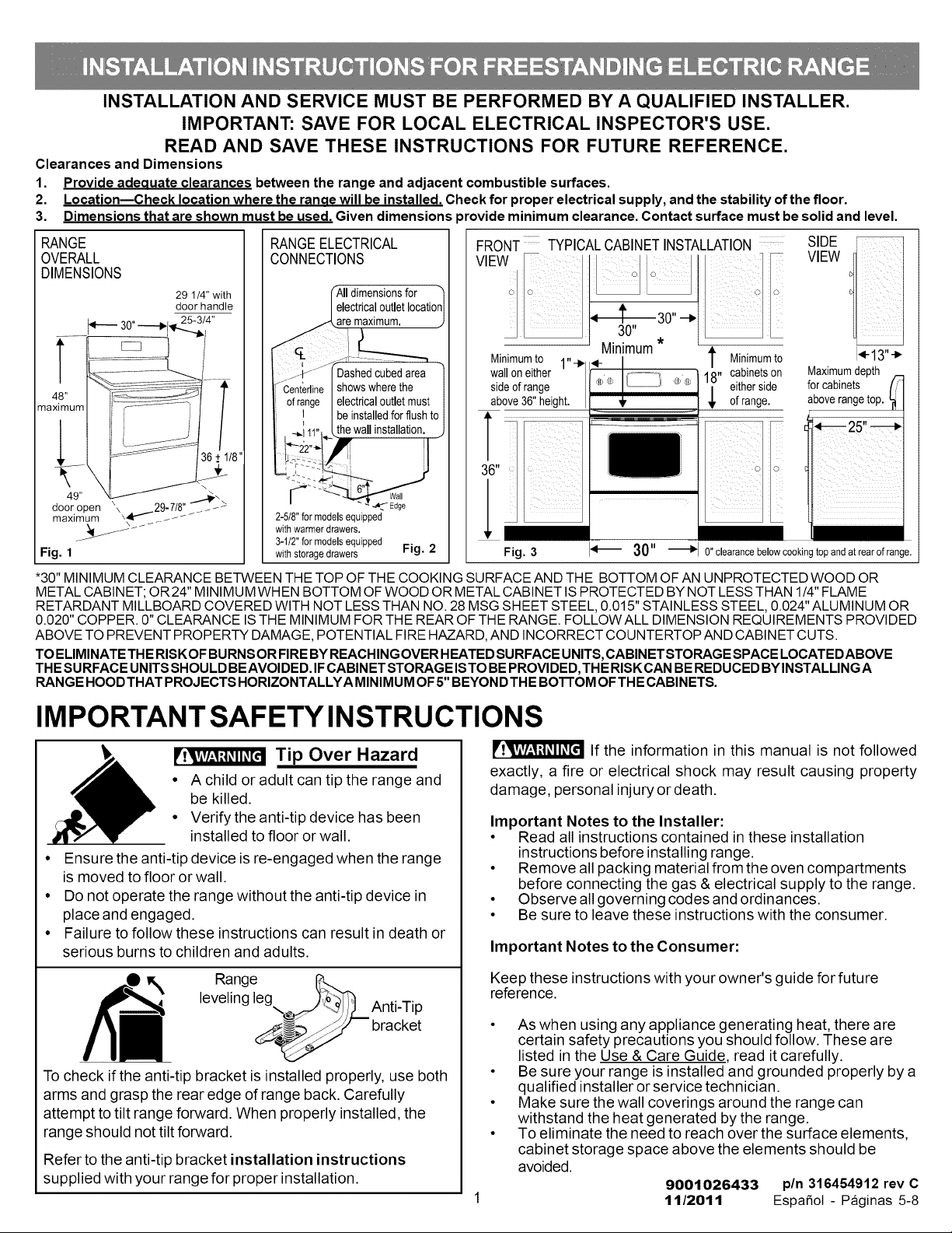
1. Provideadeauate clearancesbetweenthe rangeand adjacent combustiblesurfaces.
2. LocationmChecklocationwhere the ranae willbe installed.Checkfor properelectricalsupply,andthe stability ofthe floor.
3. Dimensionsthatare shownmust beused. Givendimensions )rovide minimumclearance.Contact surfacemustbe solidand level.
RANGE RANGEELECTRICAL FRONT TYPICALCABINETINSTALLATION SIDE
OVERALL CONNECTIONS _ VIEW
DIMENSIONS
29 1/4"with _AIIdimensionsfor
door handle I electricaloutletlocationI
' " 30" 25-3/4" jA.are maximum, j 30"
...... _ _u°--*'%' _ zji :_-':'--m. Minimum*
I __j--_"-J['Dashedcubedarea 1 -_ _-
[_CentedineI showswherethe l ®®
ma um above36"height.
ofrange I electricaloutletmust | l aboverangetop.
| ! I beinstalledforflush )1 ........................................................................
walloneither 18" cabinetson Maximumdepth
sideofrange eitherside for cabinets
_,o1: _to.13i
ofrange.
I II
_ ,___-- I.., 11.. Lthe wallinstallation, j 1_ _25,! _
door open "\\_29-7/8" _ -- " < -_ Edge
maximum __ _ _" 2-5/8"for modelsequipped
_ _ _ _ withwarmer drawers.
_ 3-1/2"for modelsequipped
Fig. 1 with storagedrawers Fig. 2 Fig. 3 _'_ 30" _ 0" clearancebelowcookingtop andat rearof range.
*30" MINIMUMCLEARANCEBETWEENTHETOPOFTHE COOKINGSURFACEANDTHE BOTTOMOFANUNPROTECTEDWOODOR
METALCABINET;OR24" MINIMUMWHENBOTTOMOFWOODORMETALCABINETISPROTECTEDBY NOTLESSTHAN 1/4"FLAME
RETARDANTMILLBOARDCOVEREDWITH NOT LESSTHAN NO.28 MSGSHEETSTEEL,0.015"STAINLESSSTEEL,0.024"ALUMINUM OR
0.020"COPPER.0"CLEARANCEISTHE MINIMUMFORTHEREAROFTHE RANGE.FOLLOWALLDIMENSIONREQUIREMENTSPROVIDED
ABOVETOPREVENTPROPERTYDAMAGE,POTENTIALFIREHAZARD,AND INCORRECTCOUNTERTOPANDCABINETCUTS.
TOELIMINATETHERISKOFBURNSORFIREBYREACHINGOVERHEATEDSURFACEUNITS,CABINETSTORAGESPACELOCATEDABOVE
THESURFACEUNITSSHOULDBEAVOIDED.IFCABINETSTORAGEISTOBEPROVIDED,THERISKCANBEREDUCEDBYINSTALLINGA
RANGEHOODTHATPROJECTSHORIZONTALLYAMINIMUMOF5"BEYONDTHEBo'n'OM OFTHECABINETS.
36+ 1/8" _:_ I
IMPORTANT SAFETY INSTRUCTIONS
• A child or adult can tip the range and
be killed.
_ Tip Over Hazard
• Verify the anti-tip device has been
installed to floor or wall.
• Ensure the anti-tip device is re-engaged when the range
is moved to floor or wall.
• Do not operate the range without the anti-tip device in
place and engaged.
• Failure to follow these instructions can result in death or
serious burns to children and adults.
leveling leg )_o'__,:,] ^_+=_-=_
_ -_/i/_ ,-,.u--.t-,
_J_i Range
To check ifthe anti-tip bracket is installed properly, use both
arms and grasp the rear edge of range back. Carefully
attempt to tilt range forward. When properly installed, the
range should not tilt forward.
Refer to the anti-tip bracket installation instructions
supplied with your range for proper installation.
__jJ bracket
exactly, a fire or electrical shock may result causing property
damage, personal injury or death.
Important Notes to the Installer:
• Read all instructions contained in these installation
• Remove all packing material from the oven compartments
• Observe all governing codes and ordinances.
• Be sure to leave these instructions with the consumer.
Important Notes to the Consumer:
Keep these instructions with your owner's guide for future
reference.
• As when using any appliance generating heat, there are
• Be sure your range is installed and grounded properly by a
• Make sure the wall coverings around the range can
• To eliminate the need to reach over the surface elements,
If the information in this manual is not followed
instructions before installing range.
before connecting the gas & electrical supply to the range.
certain safety precautions you should follow. These are
listed in the Use & Care Guide, read it carefully.
qualified installer or service technician.
withstand the heat generated by the range.
cabinet storage space above the elements should be
avoided.
9001026433 pin 316454912 rev C
1112011 Espa_ol - Paginas 5-8
BEFORE STARTING -Tools You Will Need
For leveling legs and Anti-Tip Bracket:
• Adjustable wrench or channel lock pliers
• 5/16" Nutdriver or Flat Head Screwdriver
• Electric Drill & 1/8" Diameter Drill Bit
(Masonry Drill Bit if installing in concrete)
For electrical supply connection:
• 1/4" & 3/8" Socket driver or Nutdriver
Additional Materials You Will Need:
• Power Supply Cord or
• Copper Electrical Wiring & Metal Conduit
(for hard wiring)
NORMAL INSTALLATION STEPS
1. ANTI-TIPBRACKETINSTALLATIONINSTRUCTIONS-
IMPORTANT SAFETYWARNING
To reduce the risk of tipping of the range, the range must be
secured to the floor by properly installed Anti-Tip Bracket and
screws packed with the range. Failure to install the anti-tip
bracket will allow the range to tip over if excessive weight is
placed on an open door or if a child climbs upon it. Serious
injury might result from spilled hot liquids or from the range
itself.
If range is ever moved to a different location, the Anti-Tip
Bracket must also be moved and installed with the range.
Instructions are provided for installation in wood or cement
fastened to either the floor or wall. When installed to the wall,
make sure that screws completely penetrate dry walt and are
secured in wood or metal. When fastening to the floor or wall,
be sure that screws do not penetrate electrical wiring or
plumbing.
la. Locate the Bracket using the Template - (Bracket
may be located on either the left or right side of the range. Use
the information below to locate the bracket if template is not
available).
Mark the floor or walt where
left or right side of the range
wilt be located. If rear of
range is against the walt or
no further than 1-1/4" from
wall when installed, you may
use the walt or floor mount
method. If molding is
installed and does not allow
the bracket to fit flush against the walt, remove molding or
mount bracket to the floor. For walt mount, locate the bracket by
placing the back edge of the template against the rear walt and
the side edge of template on the mark made referencing the
side of the range (See Fig. 4). Place bracket on top of template
and mark location of the screw holes in walt. If rear of range is
further than 1-1/4" from the wall when installed, attach bracket
to the floor. For floor mount, locate the bracket by placing back
edge of the template where the rear of the range wilt be
located. Mark the location of the screw holes, shown in
template.
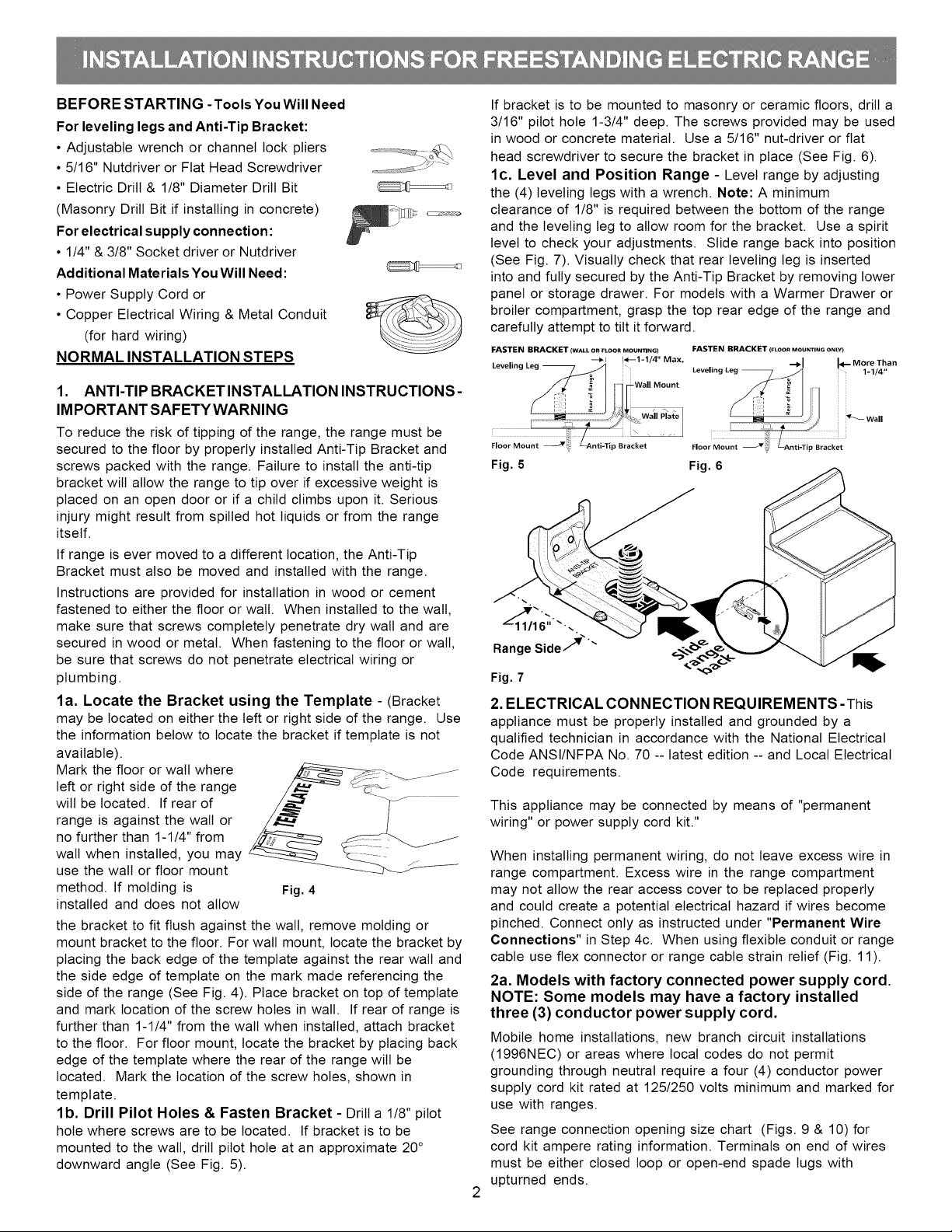
lb. Drill Pilot Holes & Fasten Bracket - Drill a 1/8" pilot
hole where screws are to be located. If bracket is to be
mounted to the walt, drill pilot hole at an approximate 20 °
downward angle (See Fig. 5).
Fig. 4
If bracket is to be mounted to masonry or ceramic floors, drill a
3/16" pilot hole 1-3/4" deep. The screws provided may be used
in wood or concrete material. Use a 5/16" nut-driver or flat
head screwdriver to secure the bracket in place (See Fig. 6).
lc. Level and Position Range - Level range by adjusting
the (4) leveling legs with a wrench. Note: A minimum
clearance of 1/8" is required between the bottom of the range
and the leveling leg to allow room for the bracket. Use a spirit
level to check your adjustments. Slide range back into position
(See Fig. 7). Visually check that rear leveling leg is inserted
into and fully secured by the Anti-Tip Bracket by removing lower
panel or storage drawer. For models with a Warmer Drawer or
broiler compartment, grasp the top rear edge of the range and
carefully attempt to tilt it forward.
FASTEN BRACKET (WALL OR FLOOR MOUN_NG) FASTEN BRACKET (FLOOR MOUNTING ONLY)
Leveling Leg -- _1 1<--1-1/4" Max. "-_1 I<-- More Than
Wall Mount
Floor Mount _i
ip Bracket
Fig. 5
Leveling Leg -- %1/4"
_Wall
Floor Mount
Bracket
Fig. 6
RangeSmde7
Fig. 7
2. ELECTRICAL CONNECTION REQUIREMENTS -This
appliance must be properly installed and grounded by a
qualified technician in accordance with the National Electrical
Code ANSI/NFPA No. 70 -- latest edition -- and Local Electrical
Code requirements.
This appliance may be connected by means of "permanent
wiring" or power supply cord kit."
When installing permanent wiring, do not leave excess wire in
range compartment. Excess wire in the range compartment
may not allow the rear access cover to be replaced properly
and could create a potential electrical hazard if wires become
pinched. Connect only as instructed under "Permanent Wire
Connections" in Step 4c. When using flexible conduit or range
cable use flex connector or range cable strain relief (Fig. 11).
2a. Models with factory connected power supply cord.
NOTE: Some models may have a factory installed
three (3) conductor power supply cord.
Mobile home installations, new branch circuit installations
(1996NEC) or areas where local codes do not permit
grounding through neutral require a four (4) conductor power
supply cord kit rated at 125/250 volts minimum and marked for
use with ranges.
See range connection opening size chart (Figs. 9 & 10) for
cord kit ampere rating information. Terminals on end of wires
must be either closed loop or open-end spade lugs with
upturned ends.
2b. MODELS REQUIRING POWER SUPPLY CORD KIT.
RISK OF FIRE OR ELECTRICAL SHOCK MAY OCCUR IF AN
INCORRECT SIZE RANGE CORD KIT IS USED, THE
INSTALLATION INSTRUCTIONS ARE NOT FOLLOWED OR
STRAIN RELIEF BRACKET IS DISCARDED.
This appliance may be connected by means of a power supply
cord. Only a power supply cord kit rated at 125/250 volts
minimum, and marked for use with ranges shall be used. See
Fig. 10 for cord kit ampere rating information. Cord must have
either three (3) or four (4) conductors (See Fig. 8). Terminals
on end of wires must be either closed loop or open-end spade
lugs with upturned ends. Cord must have strain relief properly
installed. See Steps 4a. for 4-Wire or 4b. for 3-Wire
connections.
Separate Strain Relief
before installation
Fig. 11
3. ELECTRICAL CONNECTION TO RANGE.
The Rear Access Cover must be removed (Fig 9). To remove,
loosen center screw (one screw) and remove cover. The
terminal block will then be accessible.
3 & 4 - Wire electrical wall Receptacle types &
recommended mounting orientation on wall
Required for new and
remodeled installations
4-Wire Wall
receptacle (14-50R)
existing installations
O Allowed for
Fig. 8
3 Wire Wall
receptacle (10-50R)
NOTE: Range is shipped from factory with 1-3/8" dia. hole as
shown. To use either 7/8" dia. hole or 1-1/8" dia. knockouts
refer to Fig. 9.
1-1/8" Dia. 7/8" Dia.
Knockout Hole
(See Chart) (See Chart)
Mounting
Rear
Access
Cover
Plate
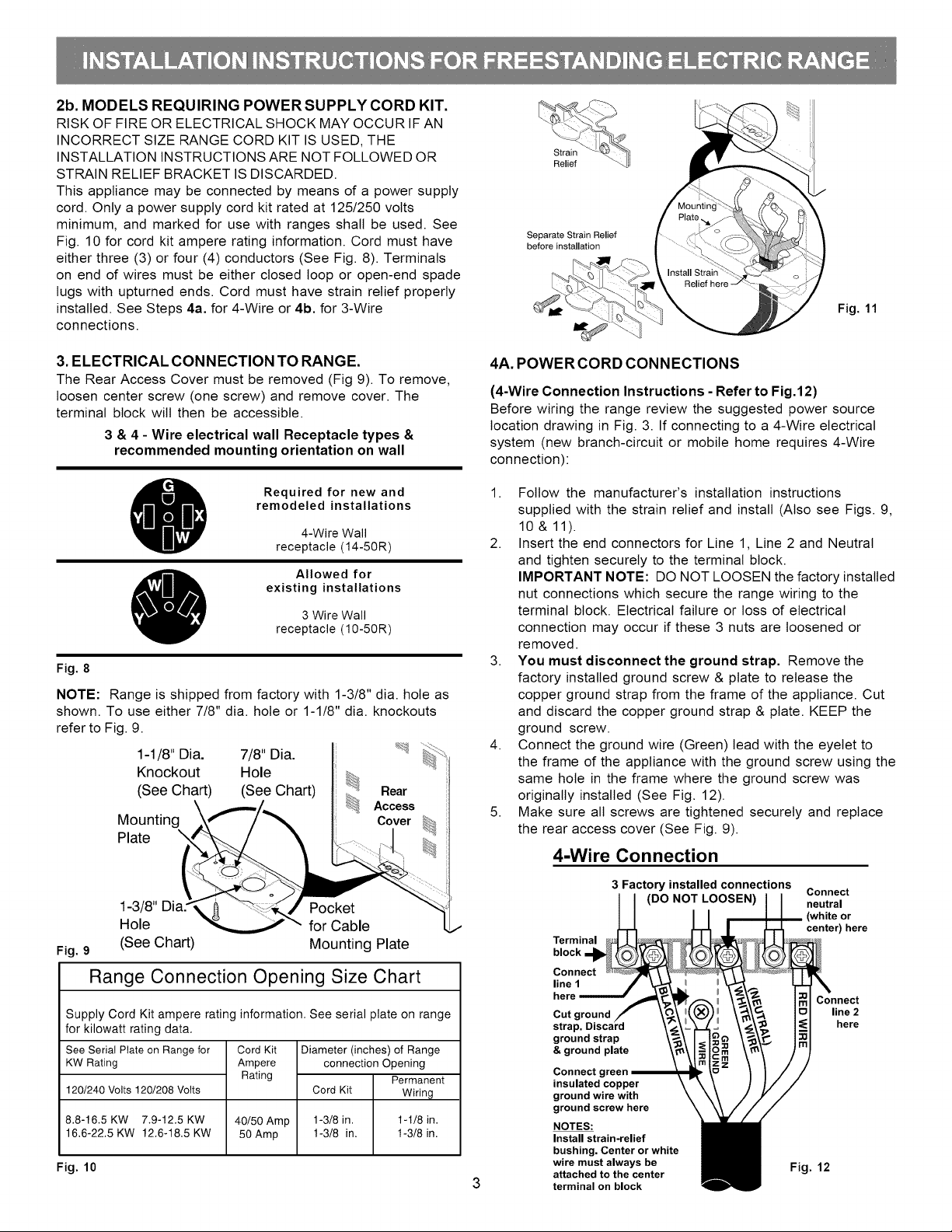
4A. POWER CORD CONNECTIONS
(4-Wire Connection Instructions - Refer to Fig.12)
Before wiring the range review the suggested power source
location drawing in Fig. 3. If connecting to a 4-Wire electrical
system (new branch-circuit or mobile home requires 4-Wire
connection):
1. Follow the manufacturer's installation instructions
supplied with the strain relief and install (Also see Figs. 9,
10 & 11).
2. Insert the end connectors for Line 1, Line 2 and Neutral
and tighten securely to the terminal block.
IMPORTANT NOTE: DO NOT LOOSEN the factory installed
nut connections which secure the range wiring to the
terminal block. Electrical failure or loss of electrical
connection may occur if these 3 nuts are loosened or
removed.
3. You must disconnect the ground strap. Remove the
factory installed ground screw & plate to release the
copper ground strap from the frame of the appliance. Cut
and discard the copper ground strap & plate. KEEP the
ground screw.
4. Connect the ground wire (Green) lead with the eyelet to
the frame of the appliance with the ground screw using the
same hole in the frame where the ground screw was
originally installed (See Fig. 12).
5. Make sure all screws are tightened securely and replace
the rear access cover (See Fig. 9).
4-Wire Connection
1-3/8" Pocket
Hole for Cable
Fig. 9 (See Chart) Mounting Plate
Range Connection Opening Size Chart
Supply Cord Kit ampere rating information. See serial plate on range
for kilowatt rating data.
See Serial Plate on Range for
KW Rating
120/240 Volts 120/208 Volts
8.8-16.5 KW 7.9-12.5 KW
16.6-22.5 KW 12.6-18.5 KW
Fig. 10
Cord Kit
Ampere
Rating
40/50 Amp
50 Amp
Diameter (inches) of Range
connection Opening
Permanent
Cord Kit Wiring
1-3/8 in. 1-1/8 in.
1-3/8 in. I-3/8 in.
3 Factory installed connections
(DO NOT LOOSEN)
Terminal
block
Connect
line 1
here
Cut ground
strap.
ground strap
& ground plate
Connect g
insulated copper
ground wire with
ground screw here
NOTES:
Install strain-relief
bushing. Center or white
wire must always be
attached to the center
terminal on block
Connect
neutral
(white or
center) here
Connect
line 2
here
Fig. 12
 Loading...