

Bosch HES23, HES34, HES43, HES25, HES24 Installation Manual
...
ELECTRIC FRFE-STANDING CONVECTION RANGE
Insta lation Manual
For Use with Model(s): all electric models
... Our Inspiration
PARTS NFEDED=
50 Amp Power Supply Cord Kit*
Measuring Tape
Phillips head Screwdriver
!=!!4"Wrench
Pencil
T=20TorxScrewdriver
Screws (2) and Anchors (2) for Anti=tip Bracket
(Style will vary depending on mounting surface)
• Level
Drill and Drill Bit
Safety Gloves and Goggles
Torque Wrench (For Hard Wire Installation Only)*
Tape (Optional)
Cloth or cardboard (Optional =to Protect Floor)
ADDITIONAL PARTS NEEDED FOR
HARD WIRE INSTALLATIONS:
Flexible Conduit (For Hard Wire Installation Only)
Torque Wrench (For Hard Wire Installation Only)
Note; Power Supply Cord Kit Not Necessary For
Hard Wire Installations
PARTS PROVIDED- _
AntFTip Bracket
Terminal Lugs (For Use With Hard Wire Installations)*
* Not necessary for Canadian installations,
_ WARNING
Before installing, turn power OFF at the service
panel. Lock service panel to prevent power
from being turned ON accidentally.
Stepping, leaning or sitting on the doors or
drawers of this range can result in serious
injuries and also cause damage to the range.
Do not allow children to climb or play around
the range. The weight of a child on an open
door may cause the range to tip, resulting in
serious burns or other injury.
Do not store items of interest to children in the
cabinets above a range or on the backguard of a
range. Children climbing on the range to reach
,_ items could be seriously injured. J
Remove all tape and packaging before using
the range. Destroy the packaging after unpacking
the range. Never allow children to play with
packaging material.
Be sure your appliance is properly installed
and grounded by a qualified technician in
accordance with the National Electrical Code ANSI!
NFPA No. 7 latest edition and local electrical code
requirements.
Important: Local codes vary. Installation, electrical
connections and grounding must comply with all
applicable codes.
:Install only per installation instructions
provided in the literature package for this
range.
• Ask your dealer to recommend a qualified
technician and an authorized repair service.
• Know how to disconnect the power to the
range at the circuit breaker or fuse box in case of
an emergency.
. Do not repair or replace any part of the
appliance unless specifically recommended
in the _anuats. All other servicing should be
done by a qualified technician. This may reduce
the risk of personal injury and damage to the
range.
• Never _odify or alter the construction of a
range by removing leveling legs, panels, wire
covers, anti=tip brackets/screws, or any other part
of the product.
DO NOT L%FT RANGE BY DOOR HANDLE.
Remove the door for easier handling and
installation. See 'Removing Oven Door' in the
Maintenance section of the Use and Care Manual.
CAUTION
Do not use the warming drawer(if equipped) or
oven for storage.
Unit is heavy and requires at least two people or
proper equipment to move.
Hidden surfaces may have sharp edges. Use
caution when reaching behind or under range.
J
English _ 1
Your Life ...
i,Insta((Venti(ation
Steps 1 through 5." Preparation
f
Bosch strongly recommends the installation of a
ventilation hood above this range, For most kitchens a
certified hood rating of not less than 300 CFM is
recommended, The range hood must be instal(ed
according to instructions furnished with the hood.
2. Prepare Cab(nets
This unit is designed for installation near adjacent walls
and projecting surfaces constructed of combustible
materials,
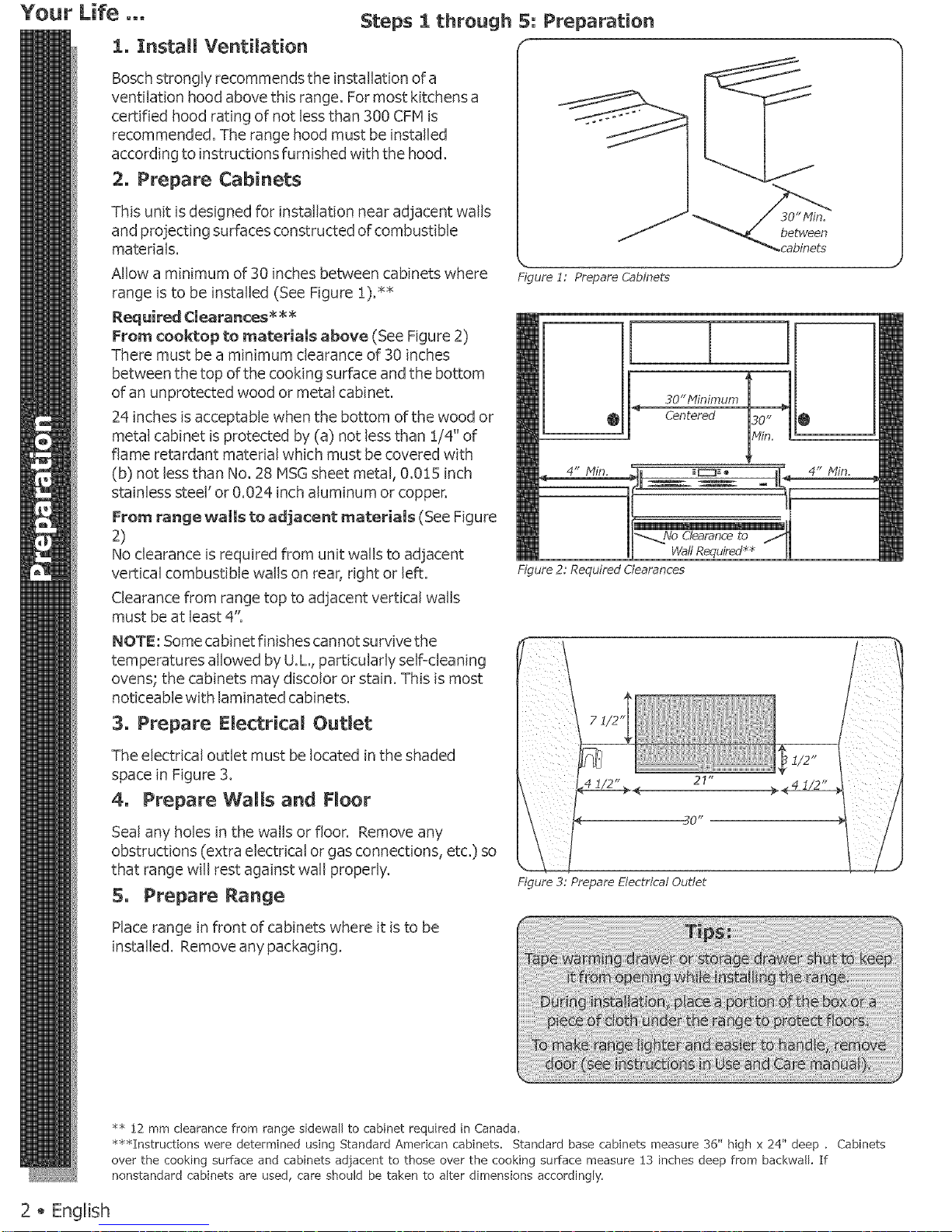
Allow a minimum of 30 inches between cabinets where
Eigure 1: Prepare Cabinets
range is to be instaUed (See Figure 1).**
Required Clearances *_
From cooktop to materials above (See Figure 2)
There must be a minimum clearance of 30 inches
between the top of the cooking surface and the bottom
of an unprotected wood or metal cabinet.
24 inches is acceptable when the bottom of the wood or
metal cabinet is protected by (a) not less than 1/4" of
flame retardant material which must be covered with
(b) not less than No. 28 MS(3sheet metal, 0.0!5 inch
stainless steel' or 0.024 inch aluminum or copper.
From range walls to adjacent materials (See Figure
No clearance is required from unit walls to adjacent
O
30"Minimum
Centered
30"
Min,
O
4" Min.
] _yo Clearance to /
Wall Requked _
4" Min,
vertical combustible walls on rear, right or left.
Clearance from range top to adjacent vertical walls
must be at least 4':
NOTE: Some cabinet finishes cannot survive the
temperatures allowed by U.L, particularly self<leaning
ovens; the cabinets may discolor or stain. This is most
noticeable with laminated cabinets.
3o Prepare Electrical Outlet
Figure 2: Required Clearances
The electrical outlet must be located in the shaded
space in Figure 3.
4. Prepare Walls and Floor
Seal any holes in the walls or floor. Remove any
obstructions (extra electrical or gas connections, etc.) so
that range wiil rest against wall properly.
Prepare Range
F{igure 3: Prepare Electrical Oudet
Place range in front of cabinets where it is to be
installed. Remove any packaging.
m
** 12 mm clearance from range sidewall to cabinet required in Canada.
***Instructions were determined using Standard American cabinets. Standard base cabinets measure 36" high x 24" deep . Cabinets
over the cooking surface and cabinets adjacent to those over the cooking surface measure 13 inches deep from backwall. If
nonstandard cabinets are used, care should be taken to alter dimensions accordingly.
2 _ English
Step 6: Preparation (cont'd)
6o Prepare Emectrical Connection
Verify that wiring to house is adequate.
Contact your local utility company to verify that the present
electric service to your home is adequate. In some
instances, the sizeof the wiring to the house and service
switch must be increased to handle the electrical load
demanded by the range.
Verify that Wiring inside house is adequate.
Most wiring codes require a separate circuit with separate
disconnect switch and fuses either in the main entrance
panel or in a separate switch and fuse box.
Most local building regulations and codes require that
electrical wiring be done by licensed electricians. Besure
to install your range according to the electric codes in place
in your region.
_ILTo prevent electri_l shock, grounding
the
prong on the range cord shouJd not be cut or
removed under any circumstances. It must be
plugged into a matching grounding type receptacle and
connected to a correctly polarized 240=Volt circuit. If there
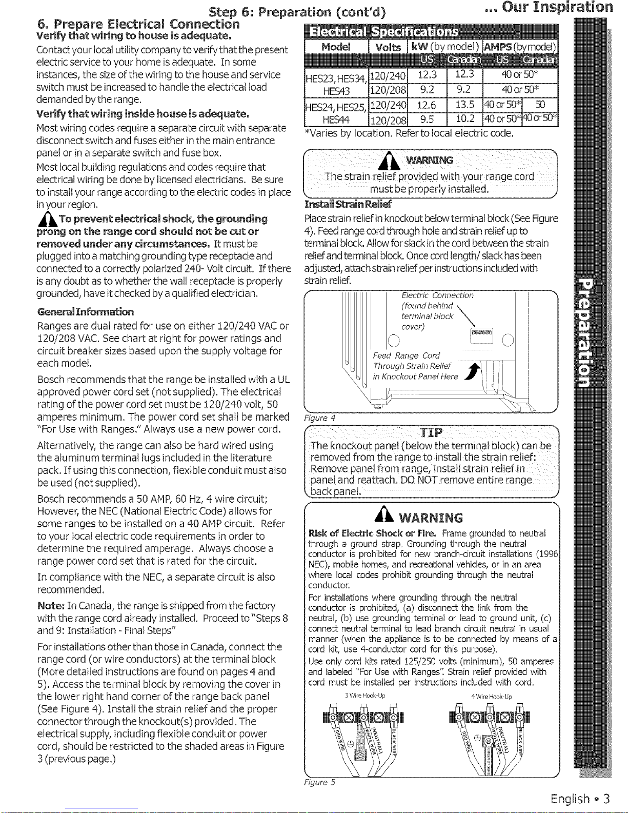
Model Volts
HES23,HES34,120/240
kW (by model)
HES43 120/208 9.2 I 9.2
qES24,HES25, 120/240 12.6 I 13.5
HESC¢ 120/208 9.5 11_0.2
_Varies by location. Referto local electric code.
The strain relief provided with your range cord
Install _rain Relief
Placestrain relief in knockout belowterminal block (SeeFigure
4). Feedrange cord through hole and strain relief upto
terminal block.Allow for slack inthe cord between the strain
reliefandterminal block.Once cord length/slack has been
adjusted, attach strain reliefper instructions includedwith
isany doubt as to whether the wall receptacle is properly
grounded, have it checked by a qualified electrician.
General Information
Ranges are dual rated for use on either :[20/240 VAC or
:[20/208 VAC. See chart at right for power ratings and
circuit breaker sizes based upon the supply voltage for
each model.
Bosch recommends that the range be installed with a UL
approved power cord set (not supplied). The electrical
rating of the power cord set must be :[20/240 volt, 50
amperes minimum. The power cord set shall be marked
strain relief.
£igure 4
Electric Connection
(found behind \
terminal block X
Feed Range Cord
Through Strain Relief _-_
in Knockout Panet Here ._ I_
i I
' '1 l\_\l
"For Usewith Ranges." Always use a new power cord.
Alternatively, the range can also be hard wired using
the aluminum terminal lugs included in the literature
pack. If using this connection, flexible conduit must also
be used (not supplied).
Bosch recommends a 50 AMP, 60 Hz, 4 wire circuit;
However, the NEC (National Electric Code) allows for
some ranges to be installed on a 40 AMP circuit. Refer
to your local electric code requirements in order to
determine the required amperage. Always choose a
range power cord set that is rated for the circuit.
In compliance with the NEC,a separate circuit is also
recommended.
Note; In Canada, the range isshipped from the factory
with the range cord already installed. Proceed to"Steps 8
and 9: Installation =Final Steps"
For installations other than those in Canada, connect the
range cord (or wire conductors) at the terminal block
(Hore detailed instructions are found on pages 4 and
5). Access the terminal block by removing the cover in
the lower right hand corner of the range back panel
(See Figure 4). Install the strain relief and the proper
connector through the knockout(s) provided. The
electrical supply, including flexible conduit or power
cord, should be restricted to the shaded areas in Figure
3 (previous page.)
TIP
_The knockout pane! (bei0w the terminal block) Canbe_
|removed from the range to instal! the strain relief:
_Remove panel from range, install strain relief in
_pane! and reattach, DO NOT remove entire range
WARNING
_.iskof Electric Shock or Fire. Framegroundedto neutral
through a ground strap. Groundingthroughthe neutral
conductoris prohibitedfor new branch<ircuitinstallations(19£
NEC),mobilehomes,andrecreationalvehicles,or inanarea
where local codesprohibitgroundingthrough the neutral
conductor.
Forinstallationswhere groundingthrough the neutral
conductoris prohibited,(a) disconnectthe linkfrom the
neutral, (b) usegroundingterminalor leadto groundunit, (c)
connectneutralterminalto lead branchcircuit neutralin usual
manner(when the applianceis to be connectedby meansof
cord kit, use4=conductorcord for this purpose).
Useonly cord kits rated 125/250volts (minimum),50 amperes
and labeled"For Usewith Ranges':Strainrelief providedwith
cord must be installedper instructionsincludedwith cord.
3 Wire Hook-Up 4-Wire Hook-Up
£igure 5
English _ 3
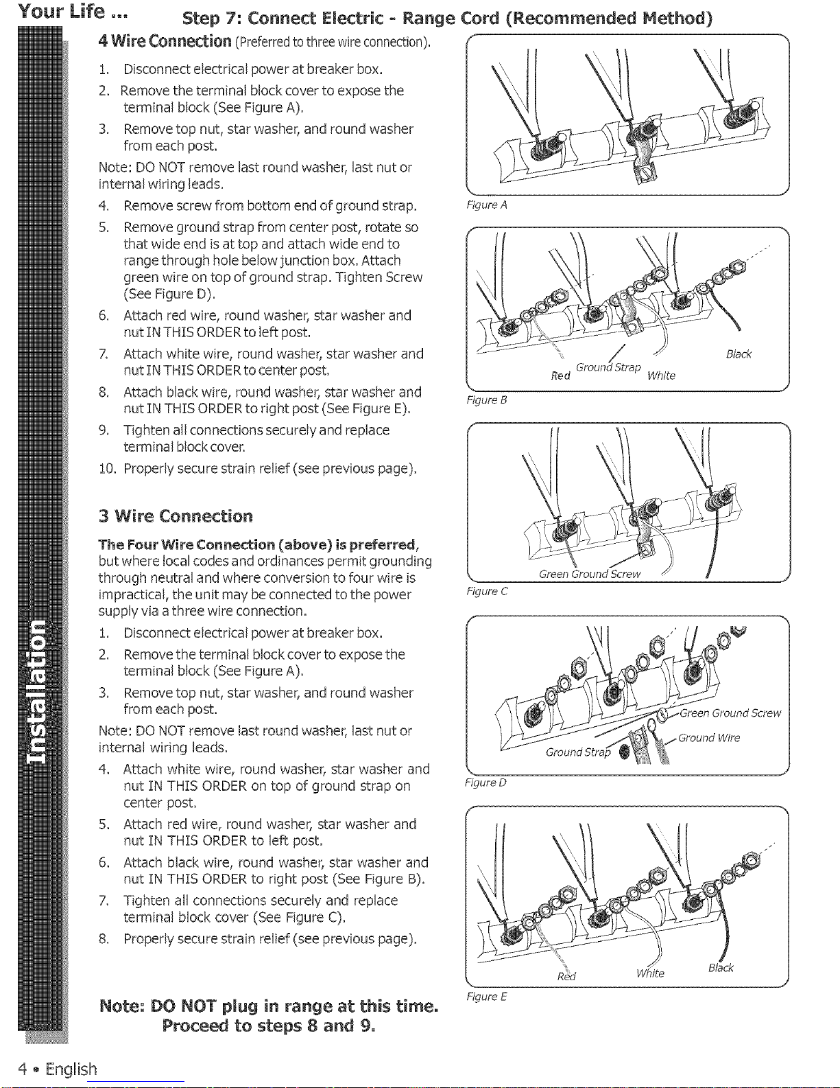
Your Life ... Step 7: Connect Electric - Range Cord (Recommended Method)
4 Wire Connection (Preferredto three wireconnection), f
!. Disconnect electrical power at breaker box.
2. Remove the terminal block cover to expose the
terminal block (See Figure A).
3. Remove top nut, star washer, and round washer
from each post.
Note: DO NOT remove last round washer, last nut or
internal wiring leads.
4. Remove screw from bottom end of ground strap.
5. Remove ground strap from center post, rotate so
that wide end is at top and attach wide end to
range through hole below junction box. Attach
green wire on top of ground strap. Tighten Screw
(See Figure D).
6. Attach red wire, round washer, star washer and
nut IN THIS ORDERto left post.
7. Attach white wire, round washer, star washer and
nut IN THIS ORDERto center post.
8. Attach black wire, round washer, star washer and
nut IN THIS ORDER to right post (See Figure E).
9. Tighten all connections securely and replace
terminal block cover.
Figure A
FigureB
10. Properly secure strain relief (see previous page).
3 Wire Connection
The Four Wire Connection (above} is preferred,
but where local codes and ordinances permit grounding
through neutral and where conversion to four wire is
impractical, the unit may be connected to the power
supply via athree wire connection.
!. Disconnect electrical power at breaker box.
2. Remove the terminal block cover to expose the
terminal block (See Figure A).
3. Remove top nut, star washer, and round washer
from each post.
Note: DO NOT remove last round washer, last nut or
internal wiring leads.
4. Attach white wire, round washer, star washer and
nut IN THIS ORDER on top of ground strap on
center post.
5. Attach red wire, round washer, star washer and
nut TNTHTS ORDER to left post.
6. Attach black wire, round washer, star washer and
nut IN THTS ORDER to right post (See Figure B).
7. Tighten all connections securely and replace
terminal block cover (See Figure C).
8. Properly secure strain relief (see previous page).
Note; DO NOT plug in range at this time,
Proceed to steps 8 and 9,
Figure C
f
J
Figure D
<
Black
Figure E
4 _ English
Note:
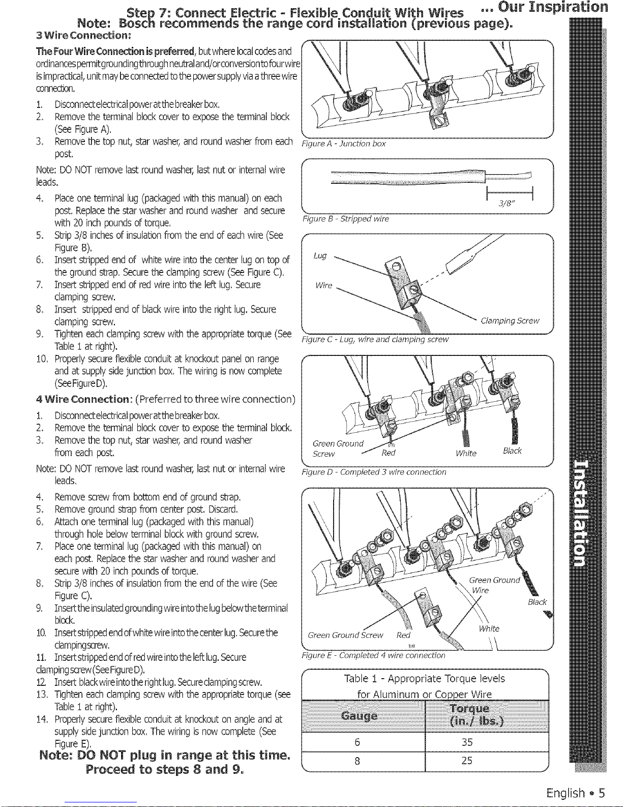
3 Wire ConneXion:
The FourWireConneXion ispreferred,butwherelocalcodesand
ordinancespermitgroundingthroughneutraland/orconversiontofourwire
isimpractical,unitmaybeconnectedtothebowersupplyviaathreewire
oonnedJon,
!. Disconnectelectricalpoweratthebreakerbox.
2. Removethe terminalblockcoverto exposethe terminalblock
(SeeFigureA).
3. Removethe top nut, starwasher,and roundwasherfrom each
post.
Note:DO NOTremovelastroundwasher,lastnut or internalwire
leads.
4. Placeoneterminallug (packagedwith this manual)on each
post.Replacethe starwasherand roundwasher andsecure
with 20 inchpoundsof torque.
5. Strip3/8 inchesof insulationfrom the endof eachwire (See
FigureB).
6. insert strippedend of white wireintothecenterlug ontop of
thegroundstrap.Securetheclampingscrew(SeeFigureC).
7. Insertstrippedendof redwire into the left lug. Secure
dampingscrew.
8. Insert strippedend of blackwireintothe right lug. Secure
dampingscrew.
9. Tighteneachclampingscrewwith the appropriatetorque(See
Table! at right).
!0. Properlysecureflexibleconduitat knockoutpanelon range
andat supplysidejunction box.Thewiring is now complete
(SeeFigureD).
4 Wire Cor_nection: (Preferred to three wire connection)
!. Disconnectelectricalpoweratthebreakerbox.
2. Removethe terminalblockcoverto exposethe terminalblock.
3. Removethe top nut, starwasher,and roundwasher
from eachpost.
Note:DO NOTremovelastroundwasher,lastnut or internalwire
leads.
4. Removescrewfrom bottomend of groundstrap.
5. Removeground strapfrom centerpost. Discard.
6. Attachoneterminallug (packagedwiththis manual)
throughholebelowterminalblockwith groundscrew.
7. Placeoneterminallug (packagedwith this manual)on
eachpost. Replacethe starwasherand roundwasherand
securewith 20 inchpoundsof torque.
8. Strip3/8 inchesof insulationfrom the endof the wire(See
FigureC).
9. Inserttheinsulatedgroundingwireintothelugbelowtheterminal
block.
!0. Insertstrippedendofwhitewireintothecenterlug.Securethe
clampingscrew.
!1. Insertstrippedendofredwireintothelef_lug.Secure
clampingscrew(SeeFigureD).
!2. Insertblackwireintotherightlug.Securedampingscrew.
!3. Tighteneachdampingscrewwith the appropriatetorque(see
Table! at right).
!4. Properlysecureflexibleconduitat knockouton angleand at
supplysidejunctionbox.The wiringis now complete(See
FigureE).
Note-" DO NOT plug in range at this time.
Proceed to steps 8 and 9.
Step 7: Connect Flectric - He×ibLe Conduit With Wires ,,. Our Inspiration
Bosch recommends the range cord installation (previous page),
\ "x
Figure B - Stripped wire
Figure. C - Lug, wire and damping screw
Clamping Bcrew
Green Ground
Screw Red White Black
Figure D - Completed 3 wire connection
Figure E - Completed 4 wire connection
Table ! - Appropriate Torque levels
for Aluminum or
6
8
35
25
English ,, 5
 Loading...