

Bosch HD18-2 Owner’s Manual
IMPORTANT: IMPORTANT : IMPORTANTE:
Read Before Using Lire avant usage Leer antes de usar
For English Version Version française Versión en español
See page 2 Voir page 12 Ver la página 22
Operating/Safety Instructions
Consignes de fonctionnement/sécurité
Instrucciones de funcionamiento y seguridad
1-877-BOSCH99 (1-877-267-2499) www.boschtools.com
Call Toll Free for
Consumer Information
& Service Locations
Pour obtenir des informations
et les adresses de nos centres
de service après-vente,
appelez ce numéro gratuit
Llame gratis para
obtener información
para el consumidor y
ubicaciones de servicio
HD18-2
BM 160992A0V9_HD18-2 4/6/15 8:21 AM Page 1
-2-
Work area safety
Keep work area clean and well lit. Cluttered
or dark areas invite accidents.
Do not operate power tools in explosive
atmospheres, such as in the presence of
flammable liquids, gases or dust. Power
tools create sparks which may ignite the dust
or fumes.
Keep children and bystanders away while
operating a power tool. Distractions can
cause you to lose control.
Electrical safety
Power tool plugs must match the outlet.
Never modify the plug in any way. Do not
us e any ada p t e r plugs w i th eart h e d
(grounded) power tools. Unmodified plugs
an d ma tchin g ou tlets wil l re duce risk o f
electric shock.
Avoid body contact with earthed or grounded
surfaces such as pipes, radiators, ranges
and refrigerators. There is an increased risk
of electric shock if your body is earthed or
grounded.
Do not expose power tools to rain or wet
conditions. Water entering a power tool will
increase the risk of electric shock.
Do not abuse the cord. Never use the cord
for carrying, pulling or unplugging the power
tool. Keep cord away from heat, oil, sharp
edges or moving parts. Damaged or entangled
cords increase the risk of electric shock.
When operating a power tool outdoors,
use an extension cord suitable for outdoor
use. Use of a cord suitable for outdoor use
reduces the risk of electric shock.
If operating a power tool in a damp location
is unavoidable, use a Ground Fault Circuit
Interrupter (GFCI) protected supply. Use of
an GFCI reduces the risk of electric shock.
Personal safety
Stay alert, watch what you are doing and
us e c ommon se nse when o pera ting a
power tool. Do not use a power tool while
you are tired or under the influence of drugs,
alcohol or medication. A moment of inattention
while operating power tools may result in
serious personal injury.
Use personal protective equipment. Always
wear eye protection. Protective equipment
such as dust mask, non-skid safety shoes, hard
hat, or hearing protection used for appropriate
conditions will reduce personal injuries.
Prevent unintentional starting. Ensure the
sw itch is in the off- posi tion be fore
connecting to power source and / or battery
pa ck, pi cking u p o r c arry ing the to ol.
Carrying power tools with your finger on the
switch or energizing power tools that have the
switch on invites accidents.
Remove any adjusting key or wrench before
turning the power tool on. A wrench or a
key left attached to a rotating part of the
power tool may result in personal injury.
Do not overreach. Keep proper footing and
balance at all times. This enables better
co ntrol of the p ower tool in une x pected
situations.
Dress properly. Do not wear loose clothing
or jewelry. Keep your hair, clothing and
gloves away from moving parts. Loose
clothes, jewelry or long hair can be caught in
moving parts.
If devices are provided for the connection
of dust extraction and collection facilities,
ensure these are connected and properly
used. Use of dust collection can reduce dust-
related hazards.
Power tool use and care
Do not forc e the pow e r too l . Use the
correct power tool for your application. The
correct power tool will do the job better and
safer at the rate for which it was designed.
Do not use the power tool if the switch does
not turn it on and off. Any power tool that
ca n n ot be cont r o l led with the swit c h is
dangerous and must be repaired.
Read all safety warnings and all instructions. Failure to follow the warnings
and instructions may result in electric shock, fire and/or serious injury.
SAVE ALL WARNINGS AND INSTRUCTIONS FOR FUTURE REFERENCE
The term “power tool” in the warnings refers to your mains-operated (corded) power tool or
battery-operated (cordless) power tool.
!
WARNING
General Power Tool Safety Warnings
BM 160992A0V9_HD18-2 4/6/15 8:21 AM Page 2
-3-
Safety Rules for Hammer Drills
Wear ear protectors with impact drilling.
Exposure to noise can cause hearing loss.
Use auxiliary handle(s), if supplied with the
tool. Loss of control can cause personal injury.
Hold power too l by insul ated gripping
surfaces, when performing an operation
where the cutting accessory may contact
hidden wiring or its own co rd. Cutti ng
accessory contacting a "live" wire may make
exposed metal parts of the power tool "live"
and could give the operator an electric shock.
Use clamps or another practical way to
secure and support the workpiece to a
stable platform. Holding the work by hand or
against your body leaves it unstable and may
lead to loss of control.
Do not drill, fasten or break into existing
walls or other blind areas where electrical
wiring ma y ex i st . If this si t u a t io n is
unavoidable, disconnect all fuses or circuit
breakers feeding this worksite.
Always wear safety gog g l e s o r e y e
protection when using this tool. Use a
dust mask or respirator for applications
which generate dust.
Use thick cushioned gloves and limit the
expo sur e t ime by t aki ng frequent r est
periods. Vibration caused by hammer-drill
action may be harmful to your hands and
arms.
Secure the material being drilled. Never
hold it in you r hand or across legs.
Unstable support can cause the drill bit to
bind causing loss of control and injury.
Position the cord clear of rotating bit. Do
not wrap the cord around your arm or
wrist. If you lose control and have the cord
wrapped around your arm or wrist it may
entrap you and cause injury.
Position yourself to avoid being caught
between the tool or side handle and walls
or posts. Should the bit become bound or
jammed in the work, the reaction torque of
the tool could crush your hand or leg.
If the bit becomes boun d in t h e
workpiece, release th e tr i g g e r
im m ediat e ly, r e verse the dir e ction of
rotation and slowly squeeze the trigger to
back out the bit. Be ready for a strong
reaction torque. The drill body will tend to
twist in the opposite direction as the drill bit is
rotating.
Do not grasp the tool or place your hands
too close to the spinning chuck or drill
bit. Your hand may be lacerated.
Disconnect the plug from the power source
a
nd/or the battery pack from the power tool
before making any adjustments, changing
accessories, or storing power tools. Such
preventive safety measures reduce the risk of
starting the power tool accidentally.
Store idle power tools out of the reach of
children and do not allow persons unfamiliar
with the power tool or these instructions to
operate the power tool. Power tools are
dangerous in the hands of untrained users.
Maintain power tools. Check for misalignment
or binding of moving parts, breakage of
parts and any other condition that may
affect the power tool’s operation. If damaged,
have the power tool repaired before use.
Ma n y a c c idents are caused by poor l y
maintained power tools.
Keep cutting tools sharp and clean. Properly
m
aintained cutting tools with sharp cutting
edges are less likely to bind and are easier to
control.
Use the power tool, accessories and tool
bits etc. in accordance with these instructions,
taking into account the working conditions
and the work to be performed. Use of the
power tool for operations different from those
intended could result in a hazardous situation.
Service
Have your power tool serviced by a qualified
re p a i r pe rson u s i n g on ly identical
replacement parts. This will ensure that the
safety of the power tool is maintained.
BM 160992A0V9_HD18-2 4/6/15 8:21 AM Page 3
-4-
When installing a drill bit, insert the shank
o
f the b i t well wi t h i n the ja w s of t h e
chuck. If the bit is not inserted deep
enough, the grip of the jaws over the bit is
reduced and the loss of control is increased.
Do not u se du l l or dam a ged b i t s an d
accessories. Dull or damaged bits have a
greater tendency to bind in the workpiece.
When removing the bit from the tool avoid
contact w i t h sk i n an d us e pr o p e r
protective gloves when grasping the bit or
accessory. Accessories may be hot after
prolonged use.
Check to see th at k eys and adjus ting
wr e n c h e s are r e m o v e d from t h e drill
before switching the tool "ON". Keys or
wr e n c h e s can f l y away a t high v e l o c ity
striking you or a bystander.
Do not run the drill while carrying it at
your side. A spinning drill bit could become
entangled with clothing and injury may result.
Additional Safety Warnings
GFCI and personal protection devices like
electrician’s rubber gloves and footwear will
further enhance your personal safety.
Do not use AC only rated tools with a DC
power supply. While the tool may appear to
work, the electrical components of the AC
rated tool are likely to fail and create a hazard
to the operator.
Keep handles dry, clean and free from oil
and grease. Slippery hands cannot safely
control the power tool.
Use clamps or other practical way to secure
and support the workpiece to a stable
platform. Holding the work by hand or against
your body is unstable and may lead to loss of
control.
Develop a periodic maintenance schedule
for your tool. When cleaning a tool b e
careful not to disassemble any portion of
th e tool sin c e inter nal wire s may be
misplaced or pinched or safety guard return
sp ring s may be improp erly mount ed.
Certain cleaning agents such as gasoline,
carbon tetrachloride, ammonia, etc. may
damage plastic parts.
Risk of injury to user. The power cord must only
be serviced by a Bosch Factory Service Center
or Autho rized Bosch Service Station.
Some dust created by power
sanding, sawing, grinding,
drilling, and other construction activities
contains chemicals known to cause cancer,
birth defects or other reproductive harm.
Some examples of these chemicals are:
• Lead from lead-based paints,
• Crystalline silica from bricks and cement and
other masonry products, and
• Arsenic and chromium from chemically-
treated lumber.
Yo u r risk f r o m these expo s u r es vari e s ,
depending on how often you do this type of
work. To reduce your expos ure to th ese
chemicals: work in a well ventilated area, and
work with approved safety equipment, such as
those dust masks that are specially designed
to filter out microscopic particles.
!
WARNING
BM 160992A0V9_HD18-2 4/6/15 8:21 AM Page 4
-5-
IMPORTANT: Some of the following symbols may be used on your tool. Please study them
and learn their meaning. Proper interpretation of these symbols will allow you to operate the
tool better and safer.
Symbol Name Designation/Explanation
V Volts Voltage (potential)
A Amperes Current
Hz Hertz Frequency (cycles per second)
W Watt Power
kg Kilograms Weight
min Minutes Time
s Seconds Time
Diameter Size of drill bits, grinding wheels, etc.
n
0
No load speed Rotational speed, at no load
n Rated speed Maximum attainable speed
.../min Revolutions or reciprocation Revolutions, strokes, surface speed,
per minute orbits etc. per minute
0 Off position Zero speed, zero torque...
1, 2, 3, ... Selector settings Speed, torque or position settings.
I, II, III, Higher number means greater speed
Infinitely variable selector with off Speed is increasing from 0 setting
Arrow Action in the direction of arrow
Alternating current Type or a characteristic of current
Direct current Type or a characteristic of current
Alternating or direct current Type or a characteristic of current
Class II construction Designates Double Insulated
Construction tools.
Earthing terminal Grounding terminal
Warning symbol Alerts user to warning messages
Li-ion RBRC seal Designates Li-ion battery recycling
program
Ni-Cad RBRC seal Designates Ni-Cad battery recycling
program
Read manual symbol Alerts user to read manual
Wear eye protection symbol Alerts user to wear eye protection
Symbols
0
BM 160992A0V9_HD18-2 4/6/15 8:21 AM Page 5
-6-
This symbol designates that this tool is listed by Underwriters Laboratories.
This symbol designates that this tool is listed by the Canadian Standards
Association.
This symbol designates that this tool is listed by the Canadian Standards
Association, to United States and Canadian Standards.
This symbol designates that this tool complies to NOM Mexican Standards.
This symbol designates that this tool is listed by the Intertek Testing
Services, to United States and Canadian Standards.
Symbols (continued)
IMPORTANT: Some of the following symbols may be used on your tool. Please study them
and learn their meaning. Proper interpretation of these symbols will allow you to operate the
tool better and safer.
This symbol designates that this component is recognized by Underwriters
Laboratories.
This symbol designates that this tool is listed by Underwriters Laboratories,
to United States and Canadian Standards.
BM 160992A0V9_HD18-2 4/6/15 8:21 AM Page 6
-7-
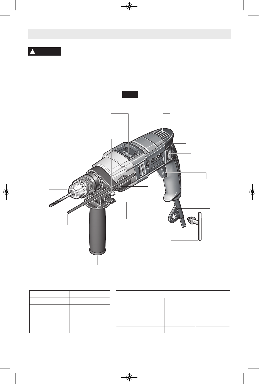
Functional Description and Specifications
D
is c onne c t th e plu g fro m the powe r sou r ce b e fore mak ing a ny
assembly, adjustments or changing accessories. Such preventive safety
measures reduce the risk of starting the tool accidentally.
!
WARNING
NOTE: For tool specifications refer to the nameplate on your tool.
REVERSING
SWITCH LEVER
VENTILATION
OPENINGS
GEAR
SELECTION
SWITCH
CHUCK
VARIABLE SPEED
CONTROLLED TRIGGER
SWITCH
AUXILIARY
HANDLE
FIG. 1
CHUCK KEY &
STORAGE AREA
DRILL/HAMMER DRILL
SELECTION SWITCH
Hammer Drill
DEPTH
GAUGE
RUBBERIZED GRIP
CORD
PROTECTOR
COLLAR MOUNT
LOCKING TEETH
SWIVEL CORD
WING KNOB
DEPTH GAUGE
RELEASE LEVER
Drilling capacities
Low Speed
(#1)
High Speed
(#2)
Concrete / Masonry 3/4" 5/8"
Steel 1/2" 1/4"
Wood 1-9/16" 1"
Model number HD18-2
No load speed 1 n0 0-1,200/min
No load speed 2 n0 0-3,200/min
Impact rate 1 0-19,200 BPM
Impact rate 2 0-51,200 BPM
Chuck capacity 1/2"
BM 160992A0V9_HD18-2 4/6/15 8:21 AM Page 7
-8-
Assembly
Disconnect the plug from
the power source before
maki ng any assembly, adjustm ents or
changing acce ssories. Such preventive
safety measures reduce the risk of starting the
tool accidentally.
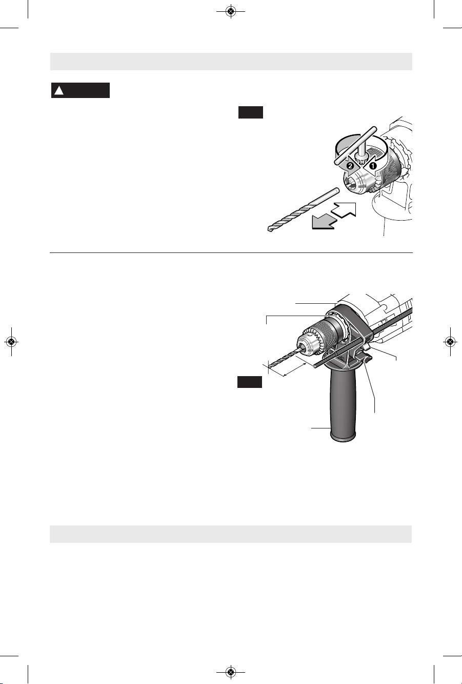
INSERTING BIT
For small bits, open jaws enough to insert the
bit up to the flutes. For large bits, insert the bit
as far as it will go. Center the bit as you close
the jaws by hand. This posit ions the bit
properly, giving maximum contact between the
chuck jaws and the bit shank.
To tighten chuck, insert key into each of the
three key holes in succession and tighten
clockwise firmly. The chuck can be released by
using one hole only (Fig. 2).
!
WARNING
C
FIG. 2
Counter
Clockwise
Clockwise
AUXILIARY HANDLE
The tool must be supported with the auxiliary
handle, which can be swiveled and locked into
12 positions 360˚ around the collar mount.
To reposition and/or swivel the handle, rotate
wing knob counterclockwise and push handle
forward until it disengages from locking teeth in
the collar mount, move handle to the desired
po sitio n and p ush handl e in ward unt il i t
engages into desired position, then securely
tighten wing knob (Fig. 3).
DEPTH GAUGE
Your drilling depth can be pre-set and/or
repeated by using the depth gauge.
Setting depth: After the auxiliary handle is
installed, make sure the accessory has been
fully inserted into the chuck before setting the
depth gauge (Fig. 3).
To adjust depth, push down on the depth
gauge release lever, slide the depth gauge to
desired depth and release pressure on lever to
lock the depth gauge in place (Fig. 3).
X
FIG. 3
Operating Instructions
VARIABLE SPEED CONTROLLED
TRIGGER SWITCH
Your tool is equipped with a variable speed trigger
switch. The tool can be turned "ON" or "OFF" by
squeezing or releasing the trigger. The speed can
be adjusted from the minimum to maximum
nameplate RPM by the pressure you apply to the
trigger. Apply more pressure to increase the
speed and release pressure to decrease speed
(Fig. 1).
LOCKING
TEETH
COLLAR MOUNT
DEPTH
GAUGE
RELEASE
LEVER
WING
KNOB
AUXILIARY
HANDLE
BM 160992A0V9_HD18-2 4/6/15 8:21 AM Page 8
-9-
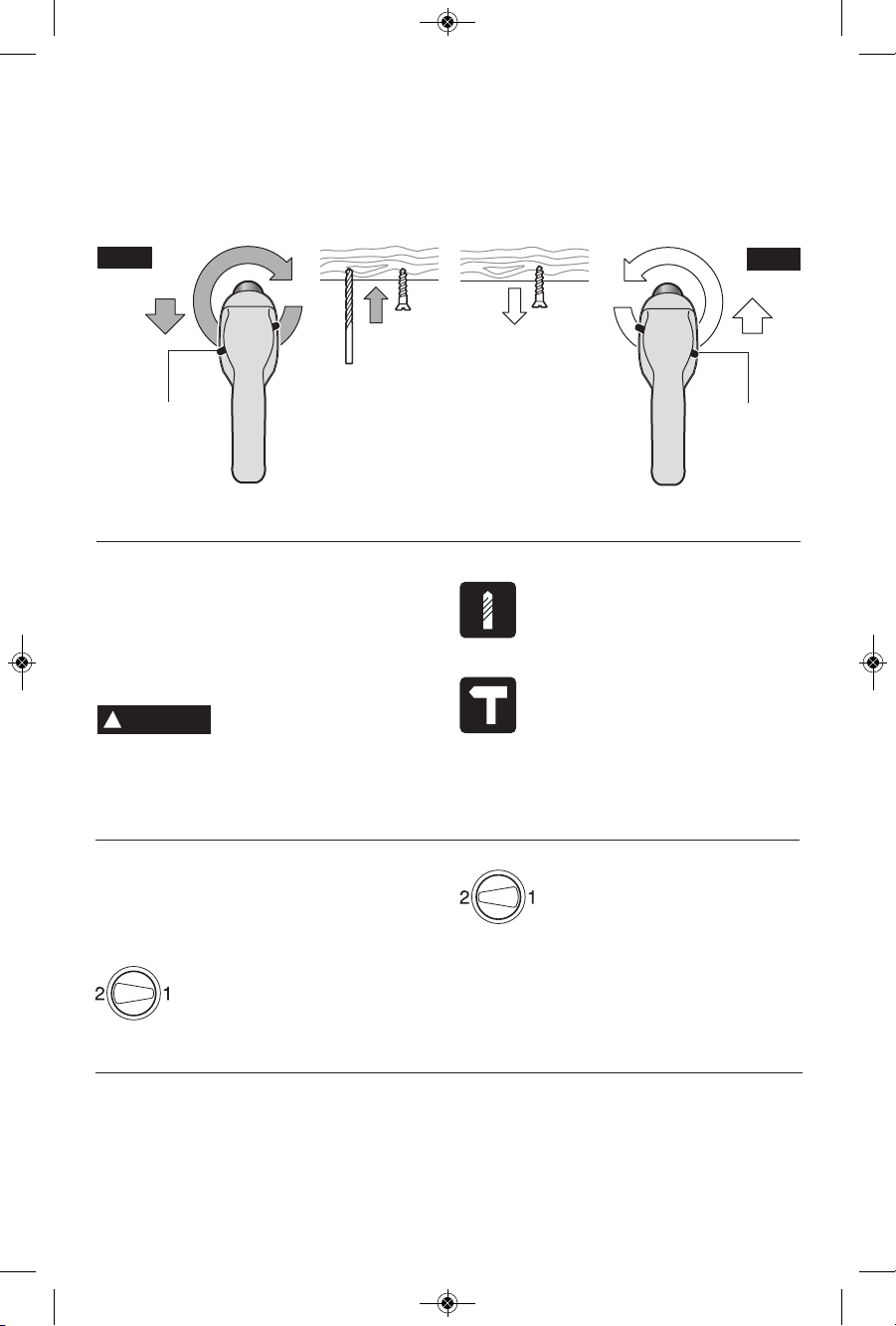
REVERSING SWITCH LEVER
This tool is equipped with a rotating brush
reversing system. This results in longer tool life
while maximizing power in both forward and re v
erse directions. The reverse switch can be
oper ated from either the right or left side of the
tool.
FOR FORWARD ROTATION: slide switch to
arrow marked forward (Fig. 4).
FOR REVERSE RO TATION: slide the slide
switch to arrow marked re verse. NOTE: Tool
will not operate in middle position (Fig. 5).
REVERSING
SWITCH
LEVER
FIG. 4
FIG. 5
REVERSING
SWITCH
LEVER
DRILL/HAMMER DRILL SELECTION
SWITCH
The selector switch allows the tool to be set for
various drilling/hammer drilling applications.
Mo ve the sele c tor s w itch right or lef t
depending on the below applications (Fig. 1).
Do no t op e rate the
selection switch until the
tool comes to a complete stop. Shifting
during rotation of the chuck can cause damage
to the tool.
Drill only action: For drilling in
woods, metals, plastics or other
non concrete materials.
Drill w ith hammer action: For
drilling in
masonry, asphalt, tile or
other similar hard materials.
!
CAUTION
GEAR SELECTION DIAL
Gear selection: The proper gear selection is
direct ly relat ed to the spee d and t orqu e
required for various jobs. The following should
be adhered to when selecting the proper gear:
Speed 1 = low speed with high
torque
Speed 2 = high speed with low
torque
Changing gears: Change gear position only
with the motor at a complete standstill. To
change gears rotate the gear selection dial. If
you have difficulties changing from one gear to
the other, turn the chuck by hand until the
gears engage (Fig. 1).
CHUCK KEY & STORAGE AREA
Your tool is equipped with a chuck key that is
conveniently located on the cord protector
where it is always handy and unlikely to get lost
or misplaced.
BM 160992A0V9_HD18-2 4/6/15 8:21 AM Page 9

You will extend the life of your bits and do
ne ater w ork i f you alwa y s put the bit in
contac t wi th t he w ork before pullin g th e
trigger. During the oper a tion, hold the tool
firmly and exert light, steady pressure. Too
much pressure at low speed will stall the tool.
Too little pressure will keep the bit from
cutting and cause excess friction by sliding
over the surface. This can be damaging to
both tool and bit.
DRILLING WITH VARIABLE SPEED
The trigger controlled variable speed feature
will eliminate the need for center punches in
hard materials. The variable speed trigger
allows you to slowly increase RPM. By using
a slow starting speed, you are able to keep
the bit from “wander ing”. You can increase
the speed as the bit “bites” into the work by
squeezing the trigger.
DRILL BITS
Always inspect drill bits for excessive wear. Use
only bits that are sharp and in good condition.
TWIST BITS: Available with straight and
reduced shanks for wood and light duty metal
drilling. High speed bits cut faster and last
longer on hard ma terials.
CARBIDE TIPPED BITS: Used for drilling
stone, con crete, plaster, cement and other
unusually hard nonmetals. Use continuous
heavy feed pres sure when employing carbide
tip bits.
DRILLING WOOD
Be certain workpiece is clamped or anchored
firm ly. Always apply pressure in a straight line
with the drill bit. Maintain enough pressure to
keep the drill “biting”.
When drilling holes in wood, twist bits can be
used. Twist bits may overheat unless pulled out
frequently to clear chips from flutes.
Use a “back-up” block of wood for work that is
likely to splinter, such as thin materials.
You will drill a cleaner hole if you ease up on
the pressure just before the bit breaks through
the wood. Then complete the hole from the
back side.
DRILLING METAL
There are two rules for drilling hard materials.
First, the harder the material, the greater the
pres sure you need to apply to the tool. Second,
the harder the material, the slower the speed.
Here are a couple of tips for drilling in metal.
Lubri cate the tip of the bit occasionally with
cutting oil except when drilling soft metals such
as alu minum, cop per or cast iron. If the hole to
be drilled is fairly large, drill a smaller hole first,
then enlarge to the required size, it’s often
faster in the lon g run . Main tain eno ugh
pressure to assure that the bit does not just
spin in the hole. This will dull the bit and greatly
shorten its life.
DRILLING MASONRY
Use carbide-tipped masonry bit for cinder block,
mortar, common brick, soft stone and other
materials. The amount of pressure to be used
is dependent upon the type of material being
drilled. Soft materials require less pressure
while the hard materials need more pressure to
prevent the drill bit from spinning.
-10-
Operating Tips
BM 160992A0V9_HD18-2 4/6/15 8:21 AM Page 10
 Loading...