

Bosch HBL 435A UC, HBL 432A UC, HBL 436A UC, HBL 442A UC, HBL 445A UC Installation Instructions Manual
...
INSTALLATION INSTRUCTION MANUAL
for
Bosch Electric Built-in
Single & Double Oven Models HBN 44../45../46..
114192
/
M
ANUEL D’INSTALLATION
f
our électrique Bosch encastré,
s
imple et double
M
odels HBN 44../45../46..

INSTALLATION INSTRUCTION MANUAL
for
Bosch Electric Built-in
Single & Double Oven Models HBN 44../45../46..
114192
BEFORE YOU BEGIN, READ THESE INSTRUCTIONS COMPLETELY AND CAREFULLY
IMPORTANT: Save these instructions for the local electrical inspector’s use
INSTALLER: Please leave this manual with owner for future reference.
OWNER: Please keep this manual for future reference

Table of Contents
INTRODUCTION ............................................................................................................................. 3
TOOLS Y O U W I L L NEED........................................................................................................ 3
POWER REQUIREMENTS ....................................................................................................... 3
CHOOSING OVEN LOCATION............................................................................................... 3
STEPS FOR INSTALLATION .................................................................................................. 3
TECHNICAL DATA......................................................................................................................... 4
SINGLE OVEN............................................................................................................................ 4
DOUBLE OVEN.......................................................................................................................... 4
UNDERCOUNTER INSTALLATION.......................................................................................... 5
SINGLE OVEN............................................................................................................................ 5
WALL INSTALLATION................................................................................................................. 6
SINGLE OVEN............................................................................................................................ 6
DOUBLE OVEN.......................................................................................................................... 7
ELECTRICAL SUPPLY.................................................................................................................. 8
WIRING REQUIREMENTS ...................................................................................................... 8
CONNECTING TO 208 VOLT CIR CUI T ............................................................................... 9
ELECTRICAL CONNECTIONS................................................................................................... 10
3-WIRE BRANCH CIRCUIT..................................................................................................... 10
4-WIRE BRANCH CIRCUIT..................................................................................................... 10
FINAL CHECKLIST........................................................................................................................ 11
2
INTRODUCTION
Please read these instructions COMPLETELY
AND CAREFULLY. They will save you time and
effort and help to ensure optimum oven performance. Be sure to observe all WARNINGS.
These installation instructions are intended for
use by a qualified installer. In addition to these instructions the oven shall be installed:
• In the United States, in accordance with the Na-
tional Electric Code/State and Municipal codes
and/or local codes.
• In Canada, in accordance with Canadian Elec-
tric Code C22.1-latest edition/Provincial and
Municipal codes and/or local codes.
These shall be carefully followed at all times.
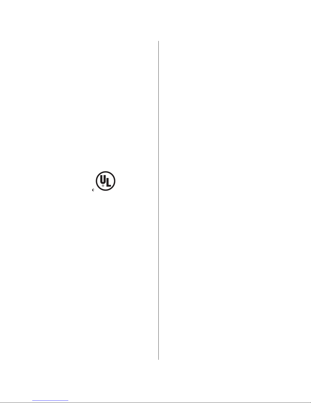
Note: If installing your oven in Canada please
check to make sure that you have a model
with the UL Canadian listing mark, as
shown below:
The UL Canadian listing mark consists of the circled UL symbol preceded by the letter “C”, as
shown. This should appear on the oven’s rating
plate along with the UL United States listing
mark, which is the circled UL symbol above but
not preceded by the letter “C”.
TOOLS YOU WILL NEED
The following tools are needed to install your new
oven:
• Tape measure and straightedge or ruler
• Pencil
• Phillips screwdriver
• Level
• Wire cutters and wire stripper
• 1" hole saw
• Hand or saber saw.
POWER REQUIREMENTS
The oven must be supplied with the proper voltage and frequency. The oven is manufactured to
be connected to a three wire or four wire, single
phase, 240 volt, 60 Hz AC electrical supply on a
separate circuit fused on both sides of the line. If
a 208 volt circuit must be used, wiring inside the
oven must be modified. See Connection to a 208
Volt Circuit, in this manual. A circuit breaker or
time-delay fuse sized not to exceed the circuit rating of the appliance specified on the rating plate
located on the frame behind the door of the oven
is recommended.
The oven must be supplied with copper wires
ONLY.
It is recommended that you have the electrical
wiring and hook-up of your oven performed by a
qualified electrician. After installation is complete have the electrician show you where the
main disconnect is and which of the circuit breakers/fuses are for the oven.
CHOOSING OVEN LOCATION
Carefully select the location where the oven will
be placed. The oven should be located for convenient use in the kitchen, but away from strong
drafts. Strong drafts may be caused by open doors
or windows, or by heating and/or air conditioning
vents or fans. Make sure that electrical power can
be provided to the location selected.
STEPS FOR INSTALLATION
The following pages provide the necessary information for proper installation of the oven arranged as follows:
• Technical Data
• Installation Cutout Dimensions, Required
Clearances and Mounting instructions for:
> Undercounter Installation, Single Oven
>Wall Installation, Single Oven
>Wall Installation, Double Oven
• Electrical Supply and Wiring Requirements
• Modifications required if Connecting to 208
Volt Circuit.
• Electrical Connections for 3-wire or 4-wire
Branch Circuit.
• Final Checklist.
3

TECHNICAL DATA
SINGLE OVEN
For cutout dimensions see fo llow ing sections titled :
Preparing Location
Single Oven
Models
Electrical Ratings
and Maximum Connected Load
Convection
Oven
Volts Hertz
Amperes
@240V/208V
Watts
@240V/208V
HBL 442A UC 240/208 60 13.5/13.6 3,250/2,820 Yes
HBL 445A UC 240/208 60 13.5/13.6 3,250/2,820 Yes
HBL 446A UC 240/208 60 13.5/13.6 3,250/2,820 Yes
DOUBLE OVEN
For cutout dimensions see fo llow ing sections titled :
Preparing Location
Double Oven
Models
Electrical Ratings
and Maximum Connected Load
Convection
Oven
(top/bottom)
Volts Hertz
Amperes
@240V/208V
Watts
@240V/208V
HBN 452A UC 240/208 60 26/26 6,250/5,400 Yes/No
HBN 455A UC 240/208 60 26/26 6,250/5,400 Yes/No
HBN 456A UC 240/208 60 26/26 6,250/5,400 Yes/No
HBN 462A UC 240/208 60 26/26 6,250/5,400 Yes/Yes
HBN 465A UC 240/208 60 26/26 6,250/5,400 Yes/Yes
HBN 466A UC 240/208 60 26/26 6,250/5,400 Yes/Yes
22-13/16"
23-1/4" height
25-5/8" width
22" depth
114204-2
48" height
47-5/8"
26-5/8" width
22" depth
114205-2
4
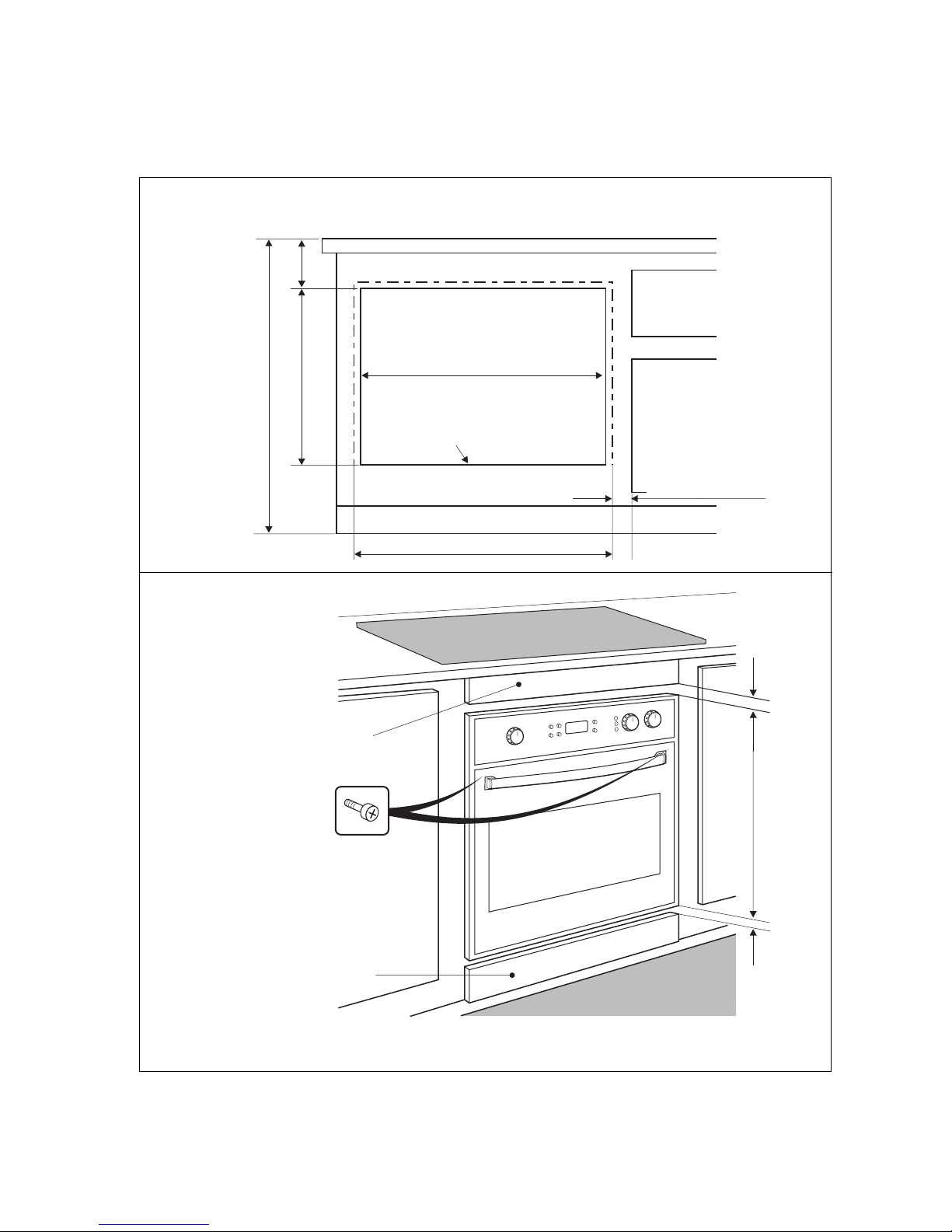
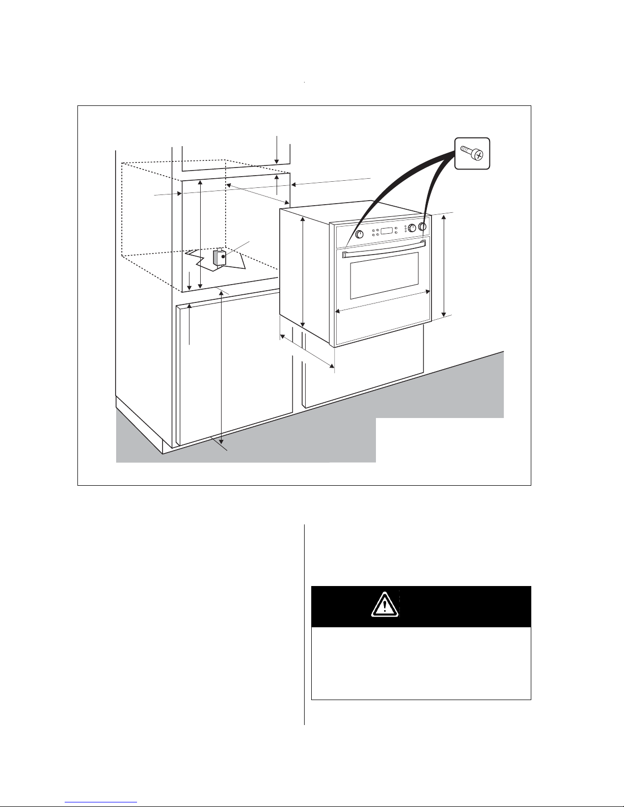
UNDERCOUNTER INSTALLATION, SINGLE
1/4 min. spacing if decorative
filler panels are used.
Note: Decorative inserts must
maintain minimum spacing as shown.
Note: Decorative inserts must
maintain minimum spacing as shown.
Oven electrical supply:
Locate junction box in
adjacent cabinet or below
bottom support surface.
Bottom support surface must
be solid, level and able to
support at least of 150 lbs.
25-3/8" opening width
toe space area
1/4" min. distance
between oven door
frame and adjacent
doors or drawer fronts.
26-5/8" width of oven door frame
36" countertop height
23" opening height
4-1/2"
min.
Secure oven to cabinet using the screws
provided. Screws should be inserted through the
mounting holes in the positions indicated in the
frame (open door to see frame and mounting
holes). Do notovertighten screws.
114206-2
Refer to and follow Notes and Warning listed under Wall Installation, Single Oven (facing page)
5
Note: 1. Do not slide oven across floor. Dam-
age to floor covering or floor could result.
2. The oven support surface must be a
minimum 3/4" thick plywood platform, solid, level and flush with the
bottom of the cabinet cutout.
3. Use extreme caution when moving or
installing the oven. It is very heavy.
4. Be very careful when moving or installing the oven to avoid damage to
the oven frame or damage to the cabinets.
5. Be sure to level oven. An oven that is
not level may provide poor or inconsistent baking results.
6. Be careful when placing oven. DO
NOT pinch the conduit between the
oven back or wall and the inner cabinet wall or floor.
Securely fasten oven to cabinet using the
screws provided. Failure to do so could result
in oven moving or tipping during use and
causing damage to the oven or cabinets or personal injury.
WARNING
1 min.
Electrical
supply
junction box
24" opening
depth
25-3/8" opening width
23" opening
height
1/4" min.
22-13/16"
23-1/4" height
26-5/8" width
34" min. recommended
so oven door, when open,
is 36" from floor.
22" depth
Secure oven to cabinet using the screws
provided. Screws should be inserted
through the mounting holes in the
positions indicated in the frame (open
door to see frame and mounting holes).
Do not overtightenscrews.
114207-2
WALL INSTALLATION, SING LE OVEN
6
Note: 1. Do not slide oven across floor. Dam-
age to floor covering or floor could result.
2. The oven support surface must be a
minimum 3/4" thick plywood platform, solid, level and flush with the
bottom of the cabinet cutout.
3. Use extreme caution when moving or
installing the oven. It is very heavy.
4. Be very careful when moving or installing the oven to avoid damage to
the oven frame or damage to the cabinets.
5. Be sure to level oven. An oven that is
not level may provide poor or inconsistent baking results.
6. Be careful when placing oven. DO
NOT pinch the conduit between the
oven back or wall and the inner cabinet wall or floor.
Securely fasten oven to cabinet using the
screws provided. Failure to do so could result
in oven moving or tipping during use and
causing damage to the oven or cabinets or personal injury.
WARNING
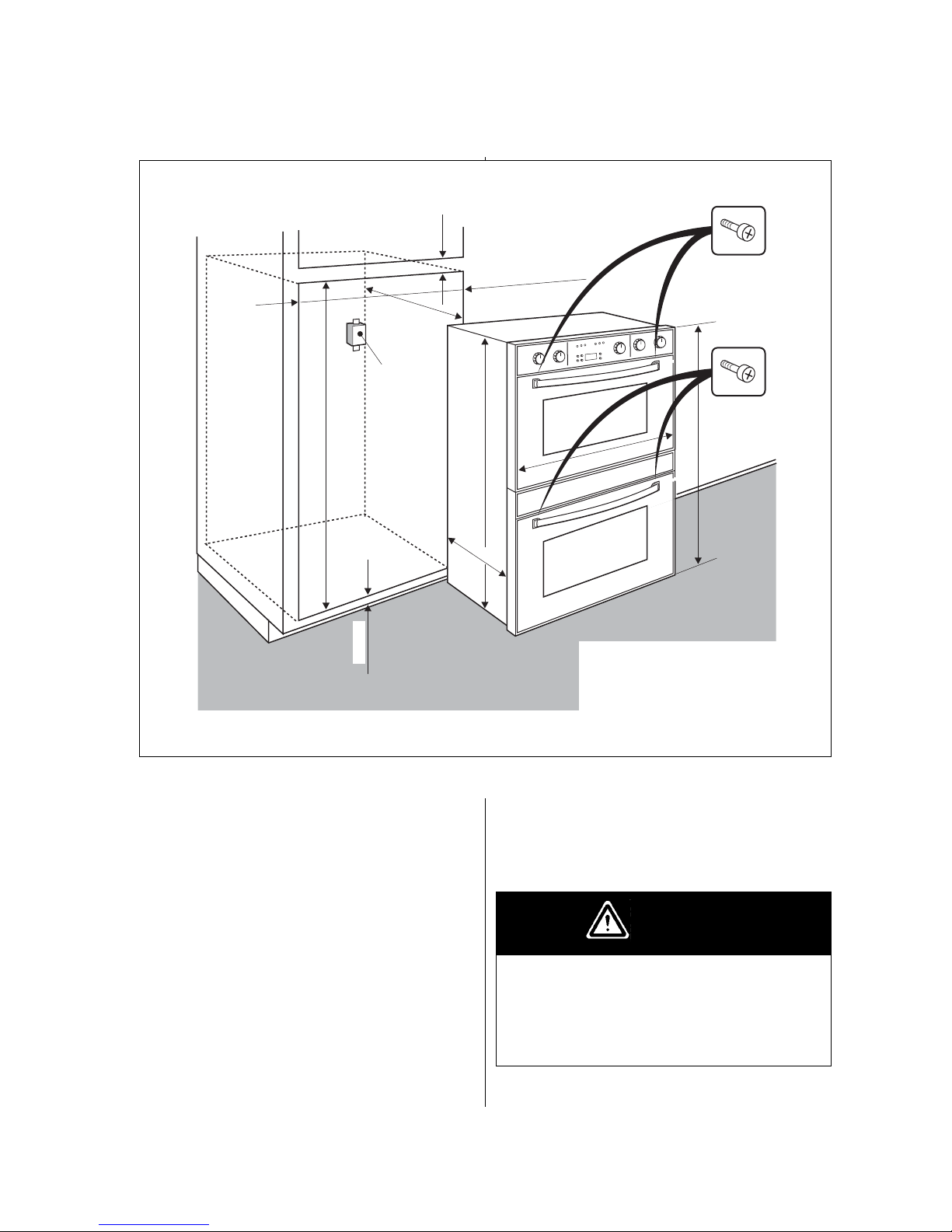
WALL INSTALLATION, DOUBLE OVEN
1 min.
Electrical
supply
junction box
24" opening
depth
25-3/8" Opening width
47-13/16" opening height
48" height
47-5/8"
26-5/8" width
22" depth
1/4" min.
Secure oven to cabinet using the screws
provided. Screws should be inserted
through the mounting holes in the
positions indicated in the frame (open
door to see frame and mounting holes).
Do not overtightenscrews.
114208-2
7
 Loading...