

Bosch GWS 7-115, GWS 7-125, GWS 10-125 C, GWS 9-125, GWS 10-125 CE Operating Instructions Manual
...
Bedienungsanleitung
Operating Instructions
Instrukcja obs¬ugi
Návod k obsluze
Návod na pouÏívanie
Használati utasítás
Руководство по
эксплуатации
Iнструкцiя з
експлуатацiї
Instrucøiuni de folosire
Ръководство за
експлоатация
Uputstvo za
opsluÏivanje
Navodilo za uporabo
Upute za uporabu
Deutsch
English
Po polsku
âesky
Slovensky
Magyar
Русский
Українська
Românå
Български
Srpski
Slovensko
Hrvatski
GWS 7-115
GWS 7-125
GWS 9-125
GWS 10-125 C
GWS 10-125 CE
GWS 14-125 C
GWS 14-125 CE
GWS 14-150 C

1 609 929 C30 • 01.01
1 605 703 099
1 600 210 039
1 603 340 031
1 603 340 040
1 607 950 043
1 602 025 024
1 601 329 013
2 602 025 121
1 601 329 013
2 605 510 192
2 605 510 193
2 605 510 194
2 605 510 182
2 605 730 036
1 600 793 007
2 605 510 187
2 605 510 188
2 605 438 404
Ø 115 mm
Ø 125 mm
Ø 150 mm
Ø 115/125 mm
Ø 150 mm
2 x
Ø 115/125 mm
1 609 929 C30 • 01.01
1 609 929 C30 • 01.01
6
DIAMOND Laser
20
8
19
10
11
18
17
1 607 000 200
0 603 999 011
4
5
6
8
9
10
11
12
2
3
16
13
14
15
12
1
7
3
6
8
9
10
11
7

Deutsch - 1
1 609 929 C30 • TMS • 15.01.01
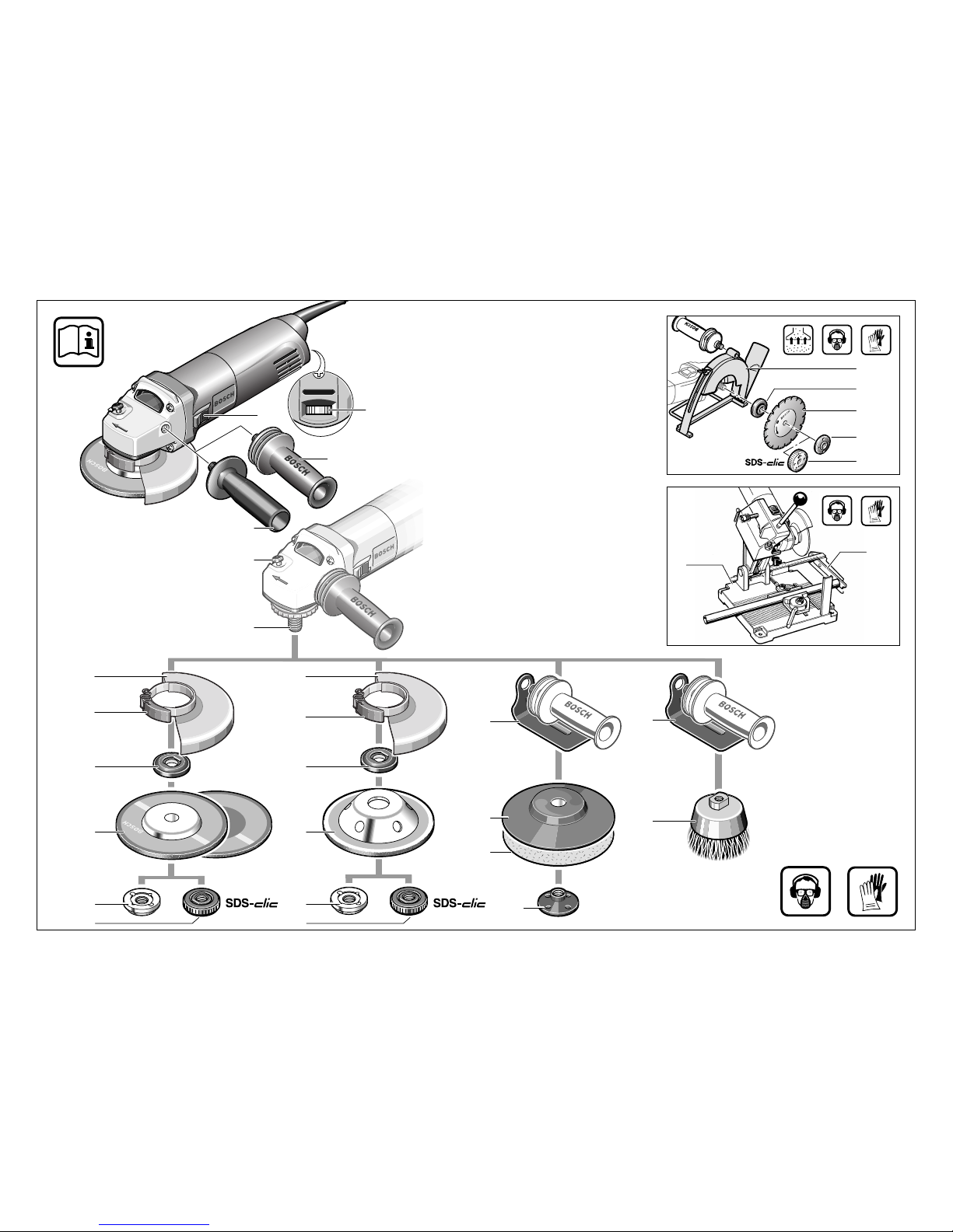
1
Stellrad Drehzahlvorwahl (Typ CE)
2
Ein-/Ausschalter
3
Zusatzgriff
4
Spindel-Arretiertaste
5
Schleifspindel
6
Schutzhaube
7
Spannhebel
8
Aufnahmeflansch mit O-Ring
9
Schrupp-/Trennscheibe*
10 Spannmutter
11 Schnellspannmutter *
12 Handschutz*
13 Gummischleifteller*
14 Schleifblatt*
15 Rundmutter*
16 Topfbürste*
17 Trennschleifständer*
18 Längenanschlag*
19 Diamant-Trennscheibe*
20 Führungsschlitten mit Absaugschutzhaube*
* Zubehör
* Abgebildetes oder beschriebenes Zubehör gehört
teilweise nicht zum Lieferumfang.
Gerätekennwerte
Winkelschleifer GWS 7-115 GWS 7-125 GWS 9-125 GWS 10-125 C
Bestellnummer 0 601 800 ... 0 601 800 048 0 601 801 ... 0 601 802 ...
Nennaufnahme* 750 W 750 W 900 W 1 020 W
Abgabeleistung* 450 W 450 W 520 W 600 W
Leerlaufdrehzahl 11 000 min
-1
11 000 min
-1
11 000 min
-1
11 000 min
-1
Schleifscheiben-Ø max. 115 mm max. 125 mm max. 125 mm max. 125 mm
Schleifspindelgewinde M 14 M 14 M 14 M 14
Anlaufstrombegrenzung – – – •
Constantelectronic – – – •
Drehzahlvorwahl – – – –
Gewicht (ohne Zubehör) ca. 1,55 kg 1,55 kg 1,60 kg 1,60 kg
Schutzklasse
/ II / II / II / II
Winkelschleifer GWS 10-125 CE GWS 14-125 C GWS 14-125 CE GWS 14-150 C
Bestellnummer 0 601 803 ... 0 601 804 ... 0 601 805 ... 0 601 806 ...
Nennaufnahme* 1 020 W 1 400 W 1 400 W 1 400 W
Abgabeleistung* 600 W 820 W 820 W 820 W
Leerlaufdrehzahl 2 800–
11 000 min
-1
11 000 min
-1
2 800–
11 000 min
-1
9 300 min
-1
Schleifscheiben-Ø max. 125 mm max. 125 mm max. 125 mm max. 150 mm
Schleifspindelgewinde M 14 M 14 M 14 M 14
Anlaufstrombegrenzung • • • •
Constantelectronic • • • •
Drehzahlvorwahl • – • –
Gewicht (ohne Zubehör) ca. 1,60 kg 1,80 kg 1,80 kg 1,85 kg
Schutzklasse
/ II / II / II / II
* Angaben gelten für Nennspannungen [U] 230/240 V. Bei niedrigeren Spannungen und in länderspezifischen
Ausführungen können diese Angaben variieren.
Geräteelemente
Deutsch - 2
1 609 929 C30 • TMS • 15.01.01
Drehzahlvorwahl (Typ CE)
Messwerte ermittelt entsprechend EN 50 144.
Der A-bewertete Geräuschpegel des Gerätes be-
trägt typischerweise: Schalldruckpegel 88 dB (A);
Schallleistungspegel 101 dB (A).
Gehörschutz tragen!
Die bewertete Beschleunigung beträgt typischerweise 5,0 m/s
2
.
Bei der Verwendung des vibrationsdämpfenden
Zusatzgriffes ist die Hand-Arm-Vibration des benutzten Elektrowerkzeuges typischerweise niedriger als 2,5 m/s
2
.
Das Gerät ist bestimmt zum Trennen, Schruppen
und Bürsten von Metall- und Steinwerkstoffen
ohne Verwendung von Wasser. Zum Trennen
von Stein ist ein Führungsschlitten vorgeschrieben.
Für Geräte mit elektronischer Steuerung: Mit zulässigen Schleifwerkzeugen kann das Gerät zum
Schleifen und Polieren verwendet werden.
Schlitze in tragenden Wänden unterliegen der
Norm DIN 1053 Teil 1 oder länderspezifischen
Festlegungen.
Diese Vorschriften sind unbedingt einzuhalten.
Vor Arbeitsbeginn den verantwortlichen Statiker,
Architekten oder die zuständige Bauleitung zu
Rate ziehen.
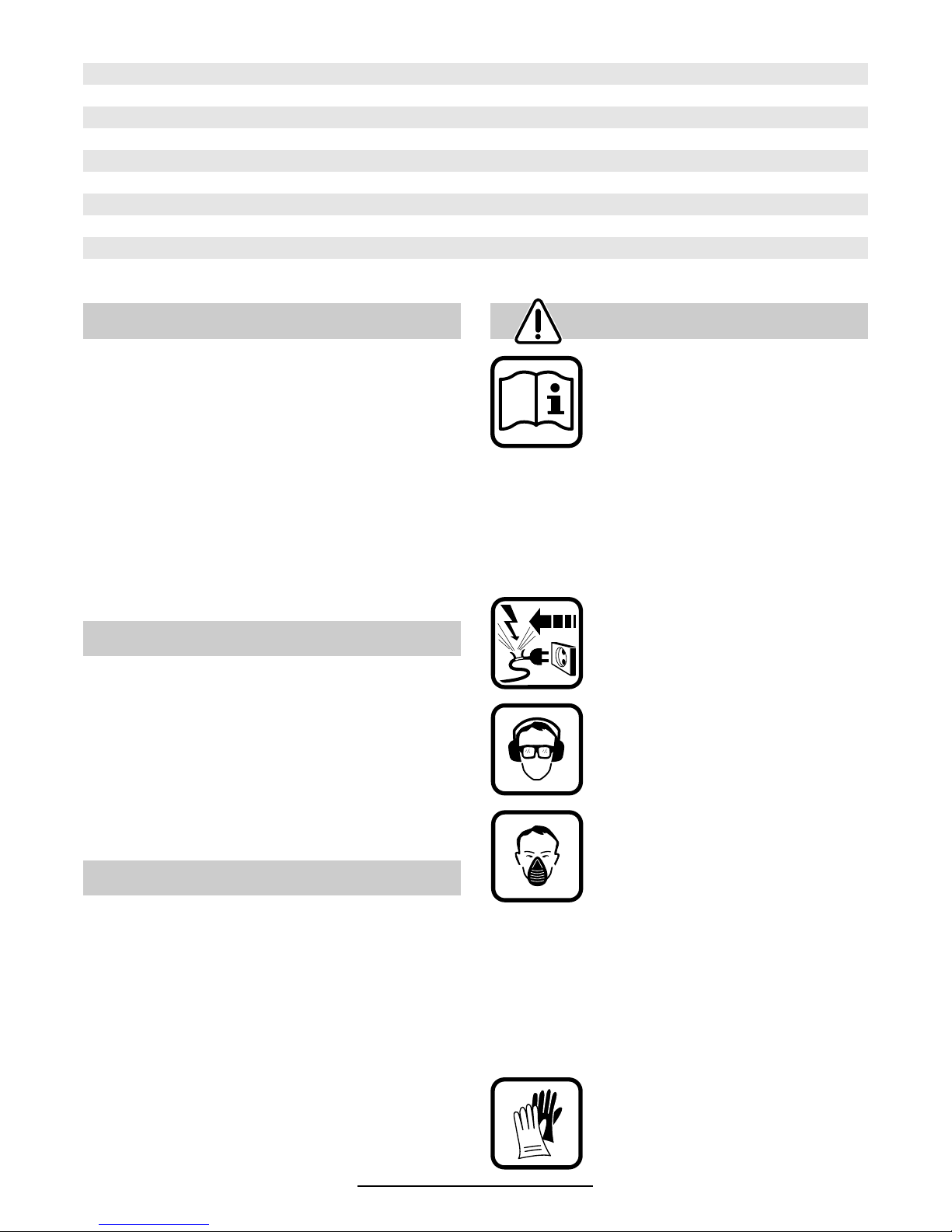
Gefahrloses Arbeiten mit dem
Gerät ist nur möglich, wenn Sie
die Bedienungsanleitung und
die Sicherheitshinweise vollständig lesen und die darin enthaltenen Anweisungen strikt befolgen. Zusätzlich müssen die
allgemeinen Sicherheitshinweise im beigelegten Heft befolgt werden. Lassen Sie sich
vor dem ersten Gebrauch praktisch einweisen.
Wird bei der Arbeit das Netzkabel
beschädigt oder durchtrennt, Kabel
nicht berühren, sondern sofort den
Netzstecker ziehen. Gerät niemals
mit beschädigtem Kabel benutzen.
Schutzbrille und Gehörschutz tragen.
Beim Arbeiten entstehende Stäube
können gesundheitsschädlich,
brennbar oder explosiv sein. Geeignete Schutzmaßnahmen sind
erforderlich.
Zum Beispiel: Manche Stäube gelten als krebserregend. Geeignete
Staub-/Späneabsaugung verwenden und Staubschutzmaske tragen.
Leichtmetallstaub kann brennen oder explodieren. Arbeitsplatz stets sauberhalten, weil Materialmischungen besonders gefährlich sind.
Schutzhandschuhe und festes
Schuhwerk tragen.
Wenn notwendig, auch Schürze
tragen.
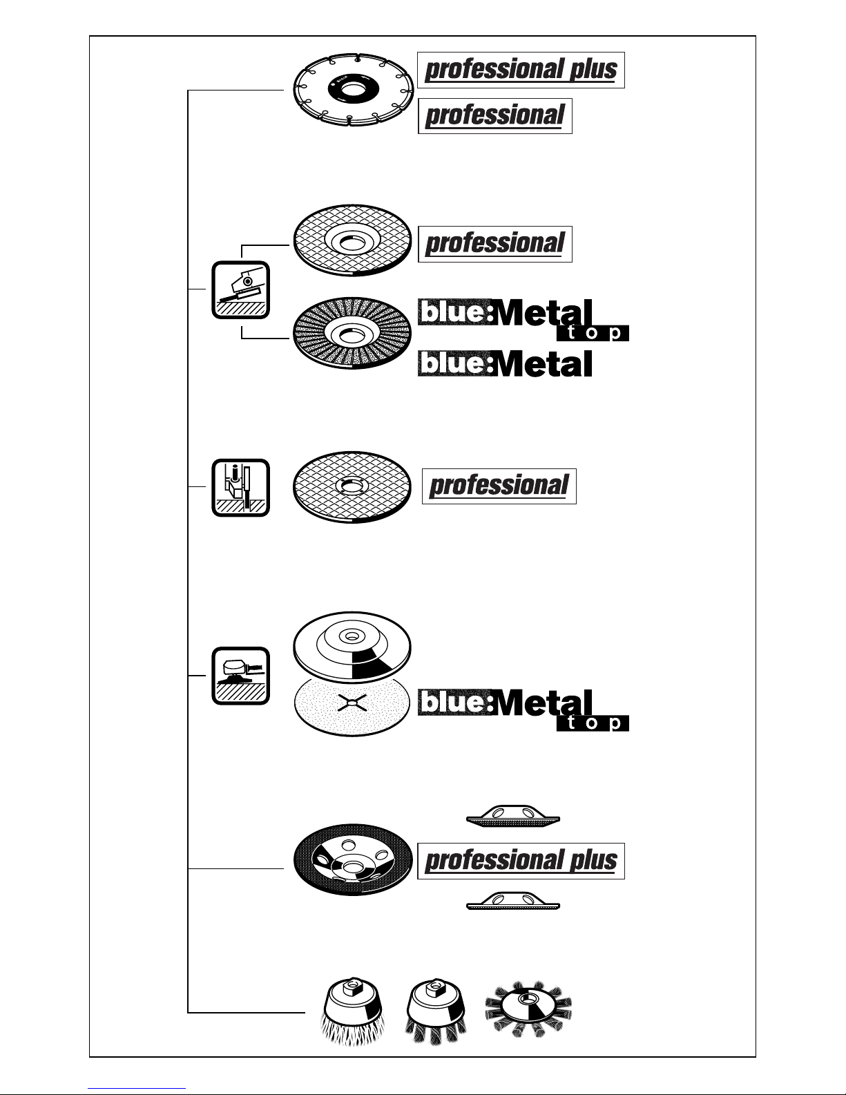
Material Anwendung Werkzeug Stellrad
Kunststoff Polieren Lammfellhaube 1
Feinschliff Filzpolierscheibe 1
Metall Feinschliff Schwabbelscheibe 1
Farbe entfernen Schleifblatt 2–3
Holz, Metall Bürsten, Entrosten Topfbürste, Schleifblatt 3
Metall, Stein Schleifen Schleifscheibe 4–6
Metall Schruppen Schruppscheibe 6
Stein* Trennen* Trennscheibe und Führungsschlitten 6
*Trennen von Gestein ist nur mit Führungsschlitten zulässig (Zubehör).
Geräusch-/Vibrationsinformation
Bestimmungsgemäßer Gebrauch
Hinweise zur Statik
Zu Ihrer Sicherheit

Deutsch - 3
1 609 929 C30 • TMS • 15.01.01
■
Geräte, die im Freien verwendet werden, über
einen Fehlerstrom-Schutzschalter (FI-) mit
maximal 30 mA Auslösestrom anschließen.
Nur ein für den Außenbereich zugelassenes
Verlängerungskabel verwenden.
■
Beim Arbeiten das Gerät immer fest mit beiden
Händen halten und für einen sicheren Stand
sorgen.
■
Kabel immer nach hinten vom Gerät wegführen.
■
Gerät vor dem Ablegen immer ausschalten
und auslaufen lassen.
■
Stecker nur bei ausgeschaltetem Gerät in die
Steckdose einstecken.
■
Bei Stromausfall oder wenn der Netzstecker
gezogen wird, den Ein-/Ausschalter sofort entriegeln und in Aus-Position bringen. Dies verhindert einen unkontrollierten Wiederanlauf.
■
Das Gerät darf nur für Trockenschnitt/Trockenschliff verwendet werden.
■
Bei allen Arbeiten mit dem Gerät muss der Zusatzgriff
3 montiert sein.
■
Das Elektrowerkzeug nur an isolierten
Handgriffen anfassen, wenn das Einsatzwerkzeug eine verborgene Leitung oder
das eigene Netzkabel treffen kann.
Kontakt mit einer spannungsführenden Leitung kann Metallteile des Gerätes unter Spannung setzen und zu einem elektrischen Schlag
führen.
■
Für Arbeiten mit Schrupp- oder Trennscheiben
muss die Schutzhaube
6
montiert sein. Für Ar-
beiten mit dem Gummischleifteller
13 oder mit
der Topfbürste
16 /Scheibenbürste/Fächer-
schleifscheibe wird empfohlen, den Handschutz
12 (Zubehör) zu montieren.
■
Beim Bearbeiten von Stein Staubabsaugung
verwenden. Der Staubsauger muss zum Absaugen von Gesteinsstaub zugelassen sein.
Zum Trennen von Stein Führungsschlitten verwenden.
■
Asbesthaltiges Material darf nicht bearbeitet
werden.
■
Nur Schleifwerkzeuge verwenden, deren zulässige Drehzahl mindestens so hoch ist wie
die Leerlaufdrehzahl des Gerätes.
■
Schleifwerkzeuge vor dem Gebrauch überprüfen. Das Schleifwerkzeug muss einwandfrei
montiert sein und sich frei drehen können. Probelauf mindestens 30 Sekunden ohne Belastung durchführen. Beschädigte, unrunde oder
vibrierende Schleifwerkzeuge nicht verwenden.
■
Schleifwerkzeug vor Schlag, Stoß und Fett
schützen.
■
Das Gerät nur eingeschaltet gegen das Werkstück führen.
■
Hände weg von rotierenden Schleifwerkzeugen.
■
Die Drehrichtung beachten. Gerät immer so
halten, dass Funken oder Schleifstaub vom
Körper weg fliegen.
■
Beim Schleifen von Metallen entsteht Funkenflug. Darauf achten, dass keine Personen gefährdet werden. Wegen der Brandgefahr dürfen sich keine brennbaren Materialien in der
Nähe (Funkenflugbereich) befinden.
■
Vorsicht beim Schlitzen z. B. in tragenden
Wänden: Siehe Hinweise zur Statik.
■
Nicht in verborgene Bereiche bohren,
schneiden oder sägen, in denen Elektro-,
Gas- oder Wasserleitungen liegen können.
Geeignete Suchgeräte verwenden, um
diese Leitungen aufzuspüren, oder die örtliche Versorgungsgesellschaft hinzuziehen.
Kontakt mit Elektroleitungen kann zu Feuer
und elektrischem Schlag führen. Beschädigung einer Gasleitung kann zur Explosion führen. Eindringen in eine Wasserleitung verursacht Sachbeschädigung oder kann elektrischen Schlag verursachen.
■
Blockieren der Trennscheibe führt zur ruckartigen Reaktionskraft des Gerätes. In diesem
Fall Gerät sofort ausschalten.
■
Abmessungen der Schleifscheiben beachten.
Lochdurchmesser muss ohne Spiel zum Aufnahmeflansch
8
passen. Keine Reduzierstü-
cke oder Adapter verwenden.
■
Niemals Trennscheiben zum Schruppschleifen verwenden. Trennscheiben keinem seitlichen Druck aussetzen.
■
Anweisung des Herstellers zur Montage und
Verwendung des Schleifwerkzeuges beachten.
■
Vorsicht! Schleifkörper läuft nach dem Ausschalten des Gerätes noch nach.
■
Gerät nicht im Schraubstock festspannen.
■
Niemals Kindern die Benutzung des Gerätes
gestatten.
■
Bosch kann nur dann eine einwandfreie Funktion des Gerätes zusichern, wenn für dieses
Gerät vorgesehenes Original-Zubehör verwendet wird.
Deutsch - 4
1 609 929 C30 • TMS • 15.01.01
■
Vor allen Arbeiten am Gerät Netzstecker
ziehen.
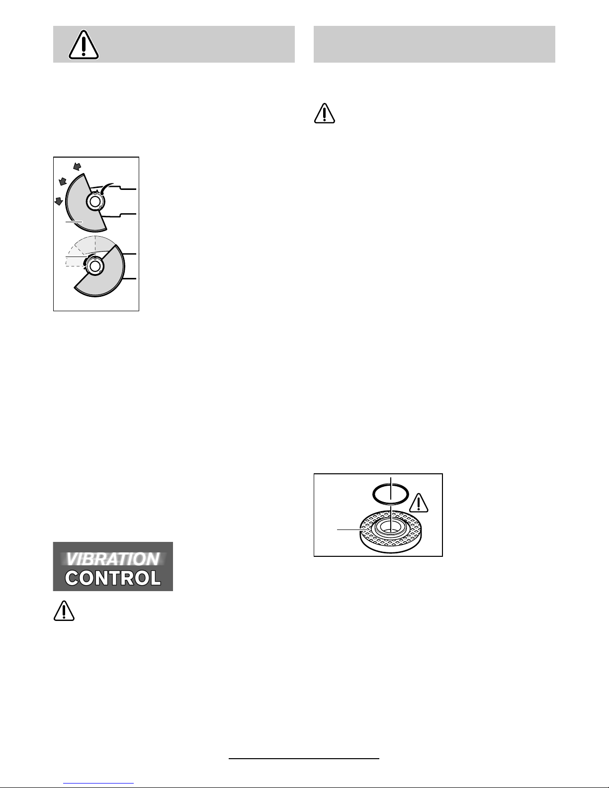
Schutzhaube
■
Für Arbeiten mit Schrupp- oder Trennscheiben muss die Schutzhaube 6 montiert
sein.
Spannhebel 7 öffnen.
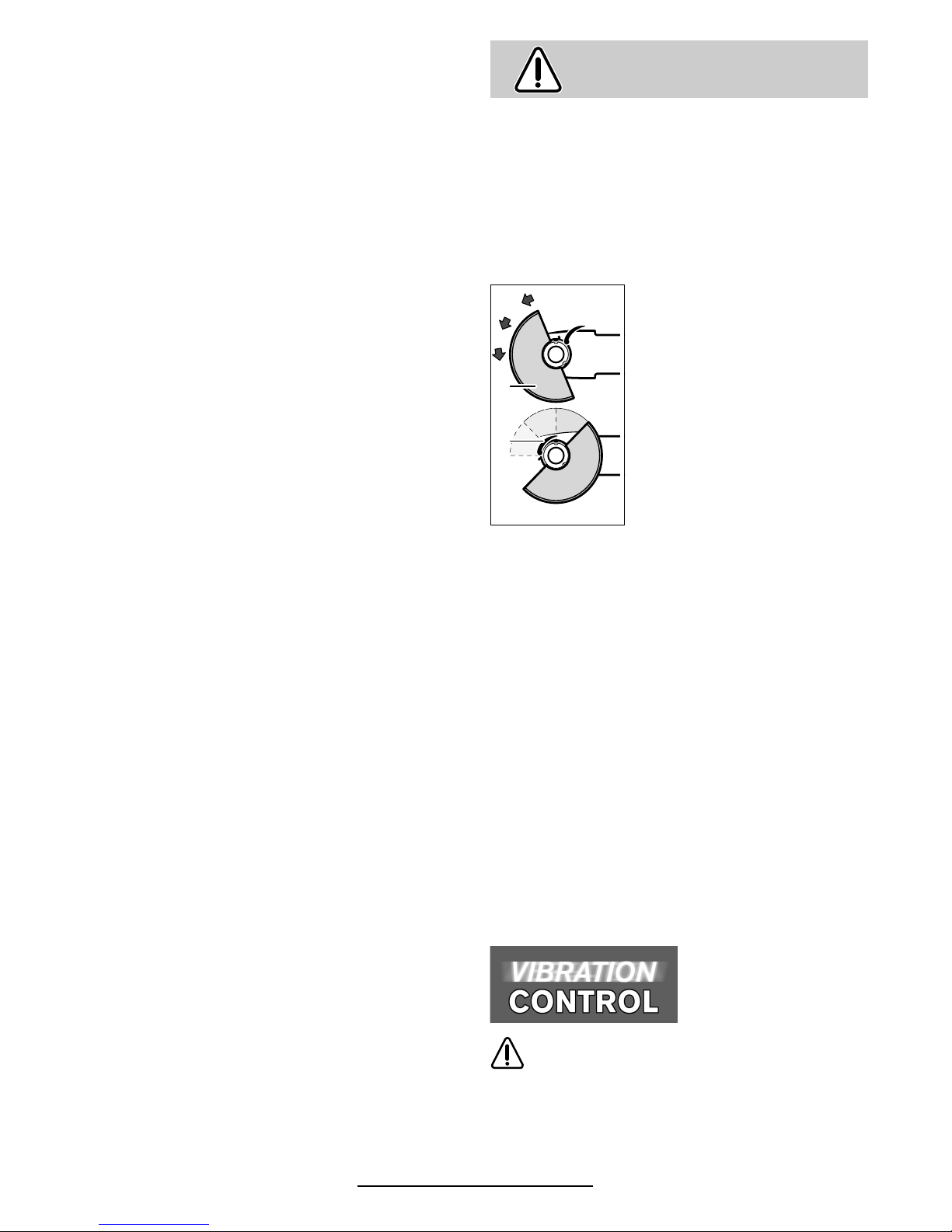
Schutzhaube
6
mit Codiernocken in Codiernut am Spindelhals des Gerätekopfes setzen
und entgegen dem Uhrzeigersinn in die erforderliche Stellung (Arbeitsposition) drehen.
Zum Festklemmen der
Schutzhaube 6 den Spannhebel 7 schließen.
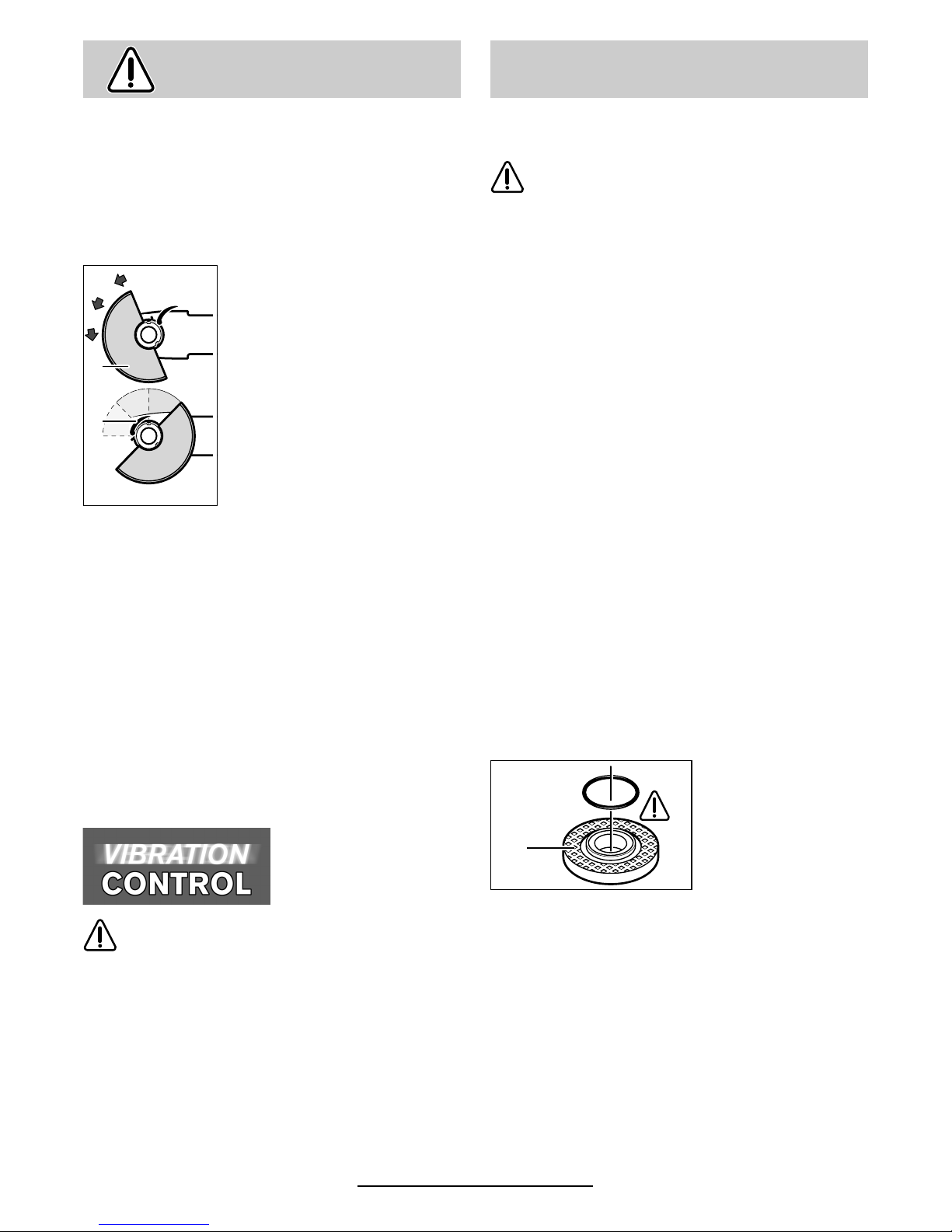
Die geschlossene Seite der
Schutzhaube 6 muss stets
zum Bediener zeigen.
Hinweis: Codiernocken an der Schutzhaube 6
stellen sicher, dass nur eine zum Gerätetyp passende Schutzhaube montiert werden kann.
Demontage in umgekehrter Reihenfolge.
Zusatzgriff
■ Bei allen Arbeiten mit dem Gerät muss der
Zusatzgriff 3 montiert sein.
Zusatzgriff 3 abhängig von der Arbeitsweise
rechts oder links am Gerätekopf einschrauben.
Vibrationsdämpfender Zusatzgriff
(Zubehör)
Keinerlei Veränderungen am Zusatzgriff
vornehmen.
Beschädigten Zusatzgriff nicht weiterverwenden.
Handschutz (Zubehör)
Für Arbeiten mit dem Gummischleifteller 13 oder
mit der Topfbürste 16/Scheibenbürste/Fächer-
schleifscheibe wird empfohlen, den Handschutz 12 (Zubehör) zu montieren. Der Hand-
schutz 12 wird mit dem Zusatzgriff 3 befestigt.
■ Vor allen Arbeiten am Gerät Netzstecker
ziehen.
Nur Schleifwerkzeuge verwenden, deren zulässige Drehzahl mindestens so
hoch ist wie die Leerlaufdrehzahl des
Gerätes.
Schrupp- und Trennscheiben werden
beim Arbeiten sehr heiß; nicht anfassen
bevor sie abgekühlt sind.
■ Schleifspindel und alle zu montierenden Teile
reinigen. Zum Festspannen und Lösen der
Schleifwerkzeuge Schleifspindel 5 feststellen
mit Spindel-Arretiertaste 4.
Spindel-Arretiertaste 4 nur bei stillstehender
Schleifspindel betätigen!
Schrupp-/Trennscheibe
■ Abmessungen der Schleifscheiben beachten.
Lochdurchmesser muss ohne Spiel zum Aufnahmeflansch 8 passen. Keine Reduzierstü-
cke oder Adapter verwenden.
Bei Verwendung einer Diamant-Trennscheibe
darauf achten, dass der Drehrichtungspfeil auf
der Diamant-Trennscheibe und die Drehrichtung
des Gerätes (Drehrichtungspfeil auf dem Gerätekopf) übereinstimmen.
Montage siehe Bildseite.
Spannmutter 10 aufschrauben und mit Zweilochschlüssel festziehen (siehe Abschnitt „Schnellspannmutter“).
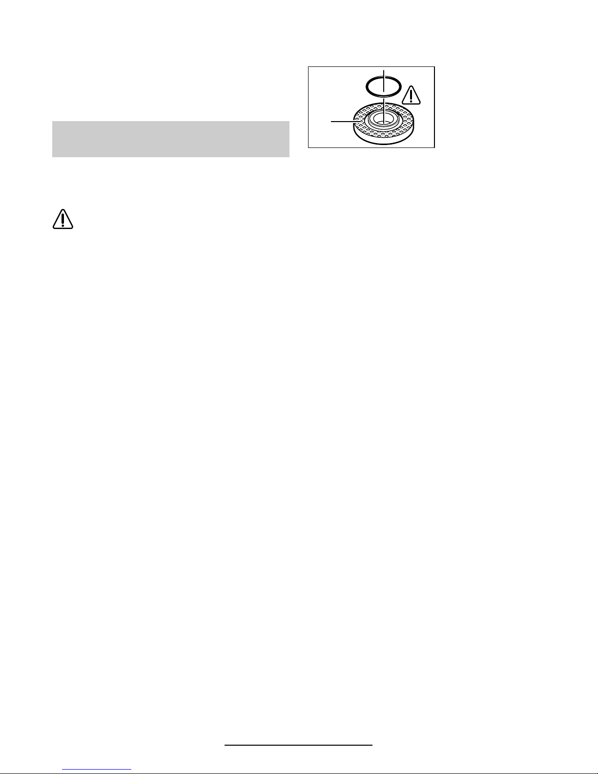
Im Aufnahmeflansch 8 ist um den
Zentrierbund ein ORing (Kunststoffteil)
eingesetzt.
Fehlt der O-Ring oder ist er beschädigt, muss
er unbedingt ersetzt werden (Bestell-Nr.
1 600 210 039), bevor der Aufnahmeflansch 8
montiert wird.
☞
Nach der Montage des Schleifwerkzeuges vor dem Einschalten prüfen, ob das
Schleifwerkzeug richtig montiert ist und
sich frei drehen kann.
Schutzvorrichtungen
montieren
6
7
Schleifwerkzeuge montieren
(Zubehör)
8
Deutsch - 5
1 609 929 C30 • TMS • 15.01.01
Fächerschleifscheibe
(Schleifmopteller)
Schutzhaube 6 abnehmen und Handschutz 12
montieren. Speziellen Aufnahmeflansch 8 (Zubehör, Bestell-Nr. 2 605 703 028) und Fächerschleifscheibe auf Schleifspindel 5 setzen.
Spannmutter 10 aufschrauben und mit Zweilochschlüssel festziehen.
Gummi-Schleifteller 13
Schutzhaube 6 abnehmen und Handschutz 12
montieren.
Montage siehe Bildseite.
Rundmutter 15 aufschrauben und mit Zweilochschlüssel festziehen.
Topfbürste 16/Scheibenbürste
Schutzhaube 6 abnehmen und Handschutz 12
montieren.
Das Schleifwerkzeug muss sich so weit auf die
Schleifspindel 5 aufschrauben lassen, dass es
am Schleifspindelflansch am Ende des Schleifspindelgewindes fest anliegt. Mit Gabelschlüssel
festziehen.
Verwendet werden können alle in dieser Bedienungsanleitung genannten Schleifwerkzeuge
(Schrupp- und Trennscheiben aus kunstharzgebundenem, faserstoffarmiertem Material).
Die zulässige Drehzahl [min
-1
] bzw. Umfangsgeschwindigkeit [m/s] der verwendeten Schleifwerkzeuge muss den Angaben in der Tabelle
mindestens entsprechen.
Deshalb stets die zulässige Drehzahl/Um-
fangsgeschwindigkeit auf dem Etikett der
Schleifwerkzeuge beachten.
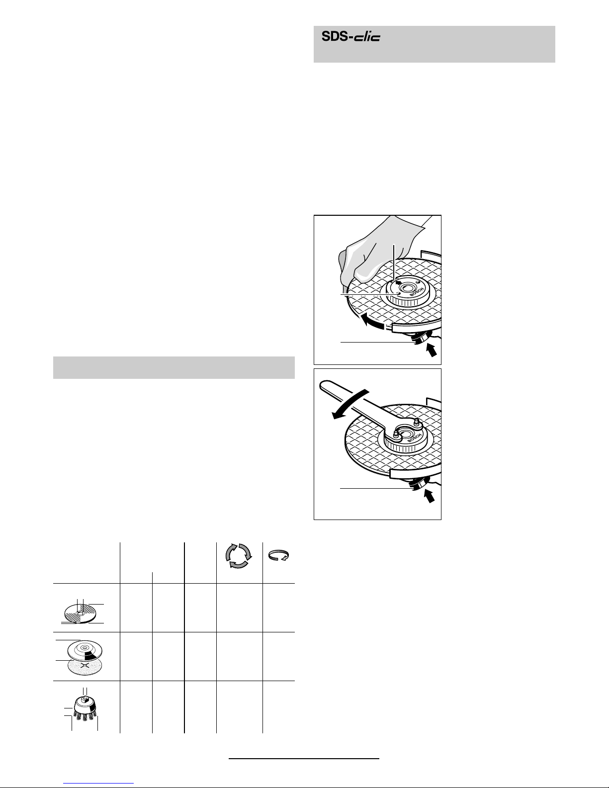
Anstelle der Spannmutter 10 kann die Schnell-
spannmutter 11 (Zubehör) verwendet werden.
Schleifwerkzeuge lassen sich dann ohne Werkzeug montieren.
Die Schnellspannmutter 11 darf nur für
Schrupp- und Trennscheiben verwendet werden.
Nur einwandfreie, unbeschädigte Schnellspannmutter 11 verwenden.
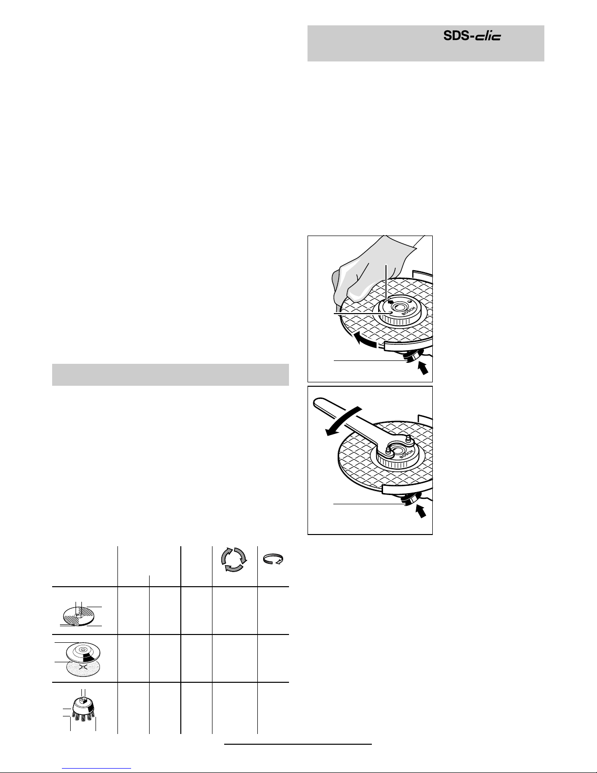
Beim Aufschrauben darauf achten, dass die beschriftete Seite nicht zur Schleifscheibe zeigt; der
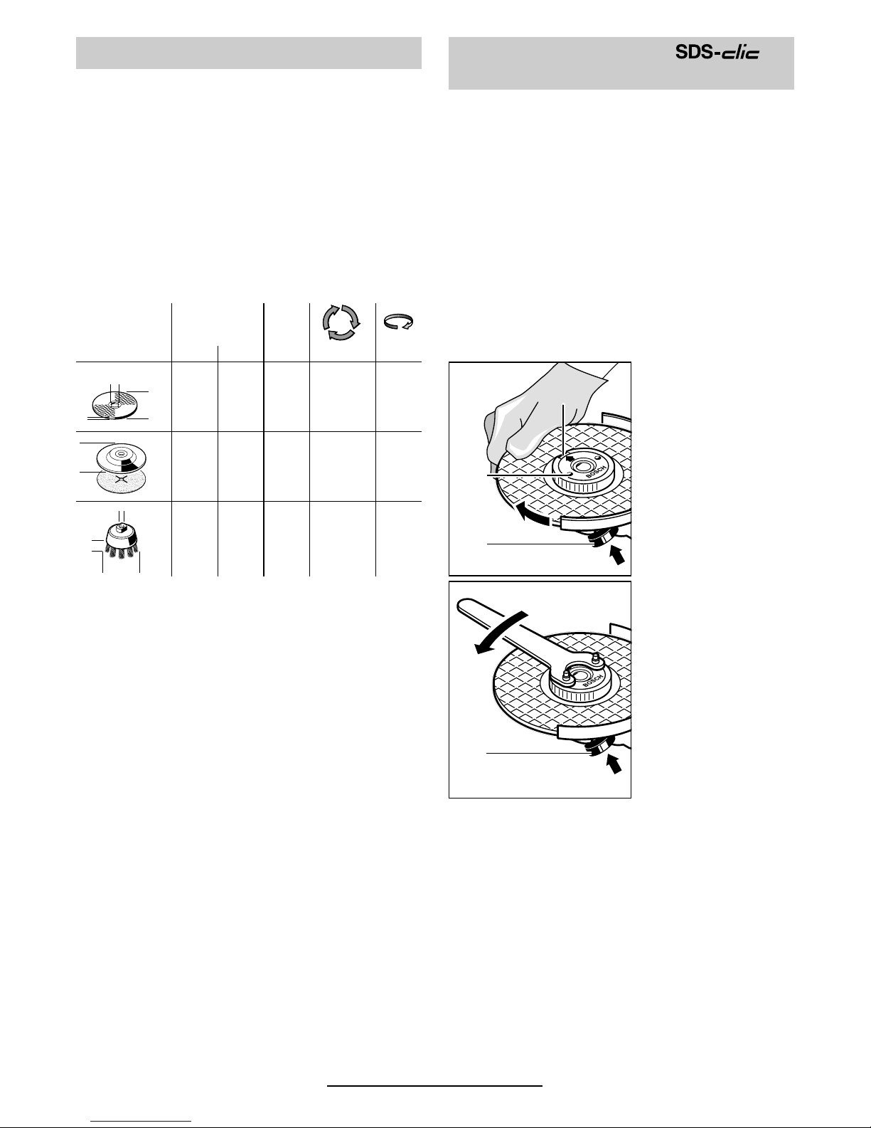
Pfeil muss auf die Indexmarke 21 zeigen.
Schleifspindel feststellen mit SpindelArretiertaste 4.
Schnellspannmutter
durch kräftiges Drehen der Schleifscheibe im Uhrzeigersinn festziehen.
Eine ordnungsgemäß befestigte unbeschädigte Schnellspannmutter lässt
sich durch Drehen
des Rändelringes
entgegen den Uhrzeigersinn von Hand
lösen.
Eine festsitzende
Schnellspannmutter nie mit einer
Zange lösen, sondern Zweilochschlüssel verwenden. Den Zweiloch-
schlüssel wie im Bild
gezeigt ansetzen.
Zulässige Schleifwerkzeuge
max.
[mm] [mm]
Dbd[min
-1
] [m/s]
115
125
150
6
6
6
22,2
22,2
22,2
11 000
11 000
9 300
80
80
80
115
125––
––11 000
11 0008080
75 30 M 14 11 000 45
b
d
D
D
D
b
d
Schnellspannmutter
(Zubehör)
4
21
11
4
Deutsch - 6
1 609 929 C30 • TMS • 15.01.01
Netzspannung beachten: Die Spannung der
Stromquelle muss mit den Angaben auf dem
Typschild des Gerätes übereinstimmen. Mit
230 V gekennzeichnete Geräte können auch an
220 V betrieben werden.
Einschalten: Ein-/Ausschalter 2 vorschieben.
Ausschalten: Ein-/Ausschalter 2 loslassen.
Arretieren: Ein-/Ausschalter 2 vorschieben
und nach vorn niederdrücken bis
er einrastet.
Ausschalten: Ein-/Ausschalter 2 hinten nieder-
drücken - Schalter springt in AusStellung.
☞
Probelauf!
Schleifwerkzeuge vor Gebrauch überprüfen. Das Schleifwerkzeug muss einwandfrei montiert sein und sich frei drehen können. Probelauf mindestens 30 Sekunden
ohne Belastung durchführen. Beschädigte,
unrunde oder vibrierende Schleifwerkzeuge nicht verwenden.
Anlaufstrombegrenzung (Typ C/CE)
Durch sanften Anlauf des Gerätes reicht eine
16-A-Sicherung aus.
Ein Gerät ohne Anlaufstrombegrenzung benötigt
eine höhere Absicherung.
Constantelectronic (Typ C/CE)
Die Constantelectronic hält die Drehzahl bei
Leerlauf und Last nahezu konstant und gewährleistet eine gleichmäßige Arbeitsleistung.
Überlastschutz
Bei Überlastung bleibt der Motor stehen. Gerät
sofort entlasten und unbelastet bei höchster
Leerlaufdrehzahl ca. 30 Sekunden abkühlen lassen.
Erforderliche Drehzahl mit Stellrad 1 gemäß der
Tabelle nach dem Abschnitt „Gerätekennwerte“
vorwählen (Anhaltswerte).
■ Werkstück einspannen, sofern es nicht
durch sein Eigengewicht sicher liegt.
■ Das Gerät nicht so stark belasten, dass es
zum Stillstand kommt.
■ Schrupp- und Trennscheiben werden beim
Arbeiten sehr heiß; nicht anfassen bevor
sie abgekühlt sind.
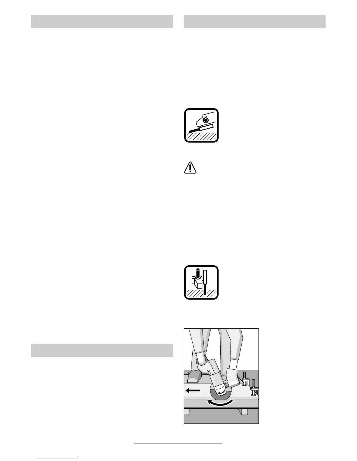
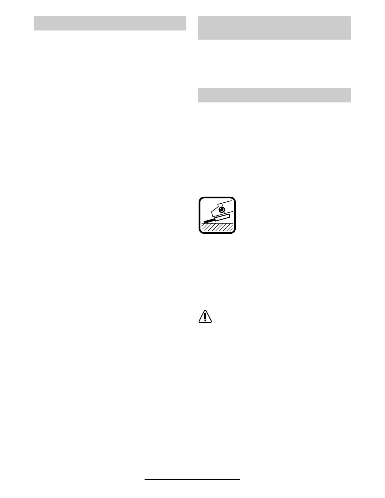
Schruppschleifen
Mit Anstellwinkeln von 30° bis 40°
erreicht man beim Schruppen das
beste Ergebnis. Gerät mit mäßigem Druck hin- und her bewegen.
Dadurch wird das Werkstück nicht
zu heiß, verfärbt sich nicht, und es
gibt keine Rillen.
Niemals Trennscheiben zum Schruppen
verwenden.
Fächerschleifscheibe
(Schleifmopteller)
Mit der Fächerschleifscheibe (Zubehör) lassen
sich auch gewölbte Oberflächen und Profile
(Konturenschliff) bearbeiten.
Fächerschleifscheiben haben wesentlich höhere
Standzeiten als Schleifblätter, geringere Geräuschpegel und niedrigere Schleiftemperaturen.
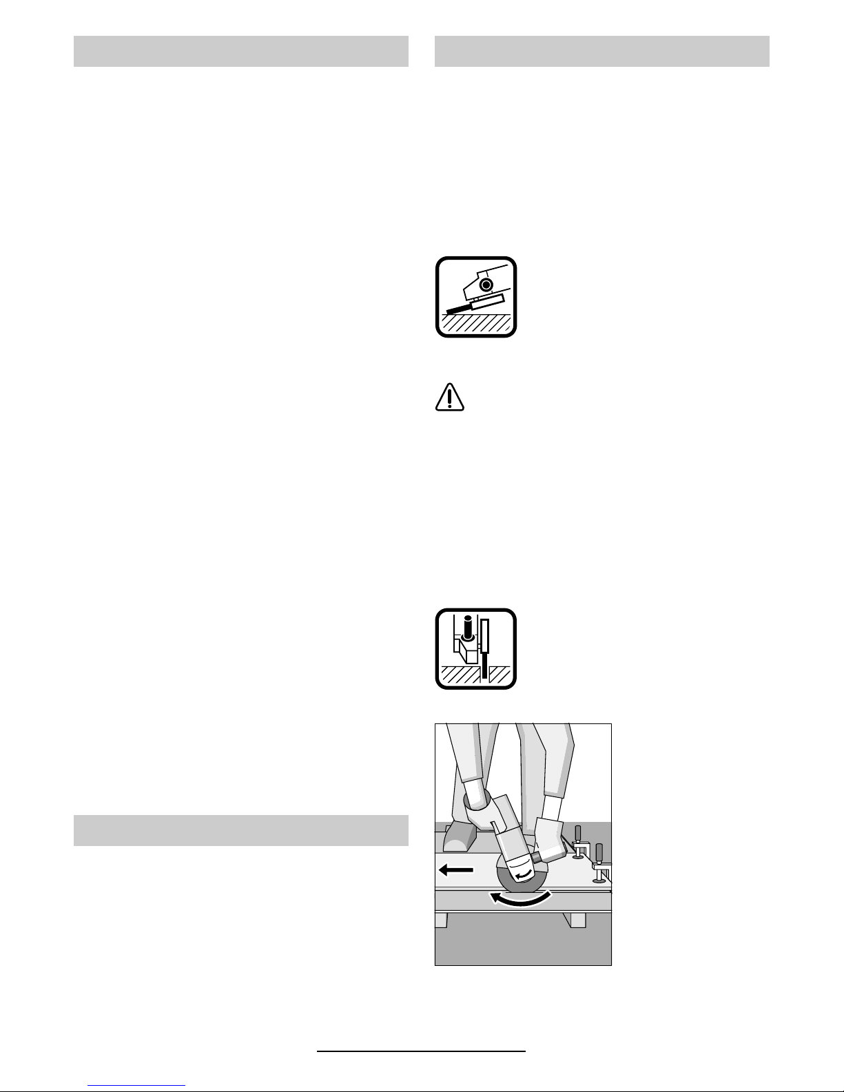
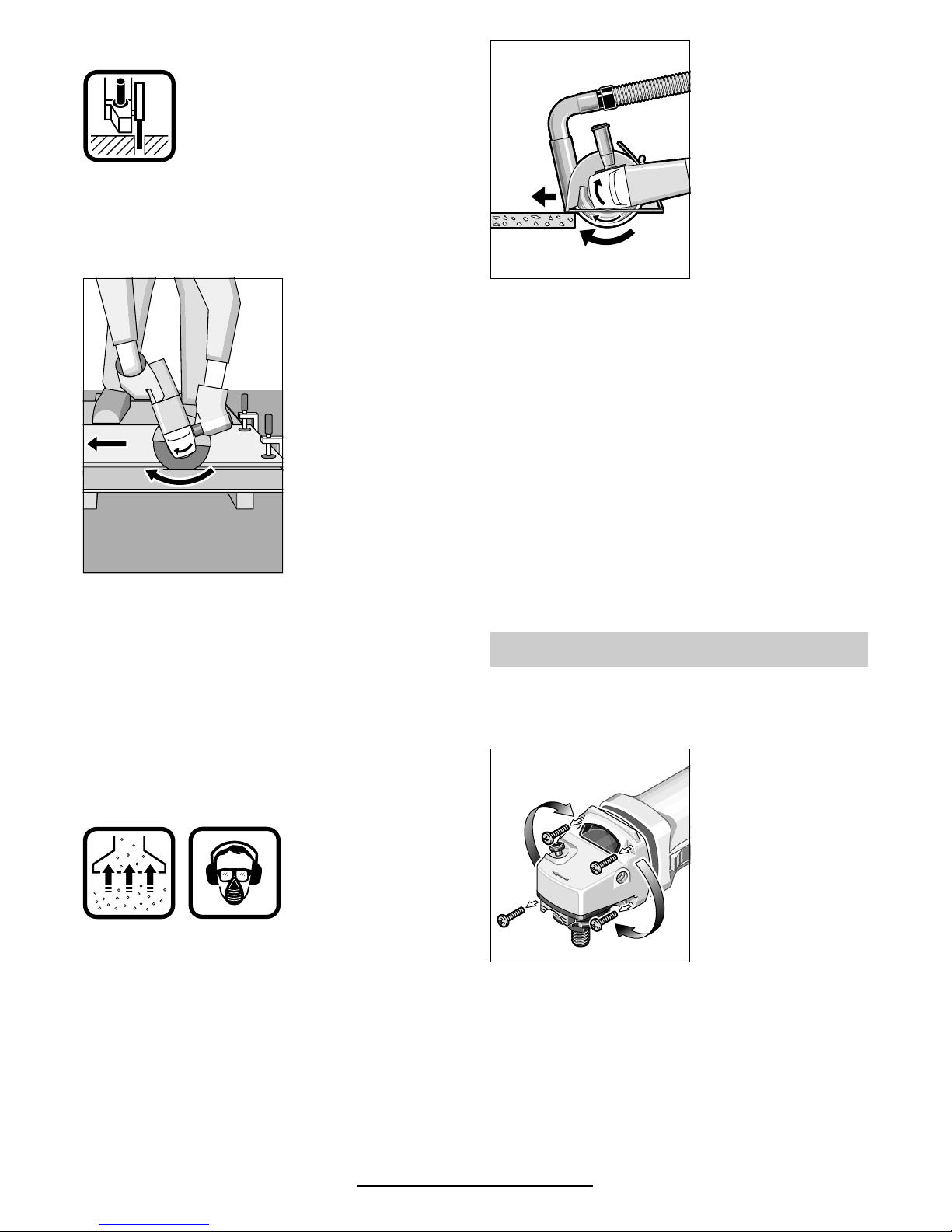
Trennschleifen
Beim Trennschleifen nicht drücken,
nicht verkanten, nicht oszillieren.
Mit mäßigem, dem zu bearbeitendem Material angepasstem Vorschub arbeiten.
Auslaufende Trennschleifscheiben
nicht durch seitliches Gegendrücken abbremsen.
Wichtig ist die Richtung, nach der man
trennt.
Das Gerät muss
stets im Gegenlauf
arbeiten; deshalb mit
dem Gerät nicht in
die andere Richtung
fahren! Es besteht
sonst die Gefahr,
dass es unkontrol-
liert aus dem Schnitt
gedrückt wird.
Inbetriebnahme
Drehzahlvorwahl (Typ CE)
Arbeitshinweise
Deutsch - 7
1 609 929 C30 • TMS • 15.01.01
Trennschleifständer
Mit dem Trennschleifständer 17 (Zubehör) kön-
nen Werkstücke längengleich im Winkel von
0 bis 45° zugeschnitten werden.
Beim Trennen von Profilen und Vierkantrohren
am besten am kleinsten Querschnitt ansetzen.
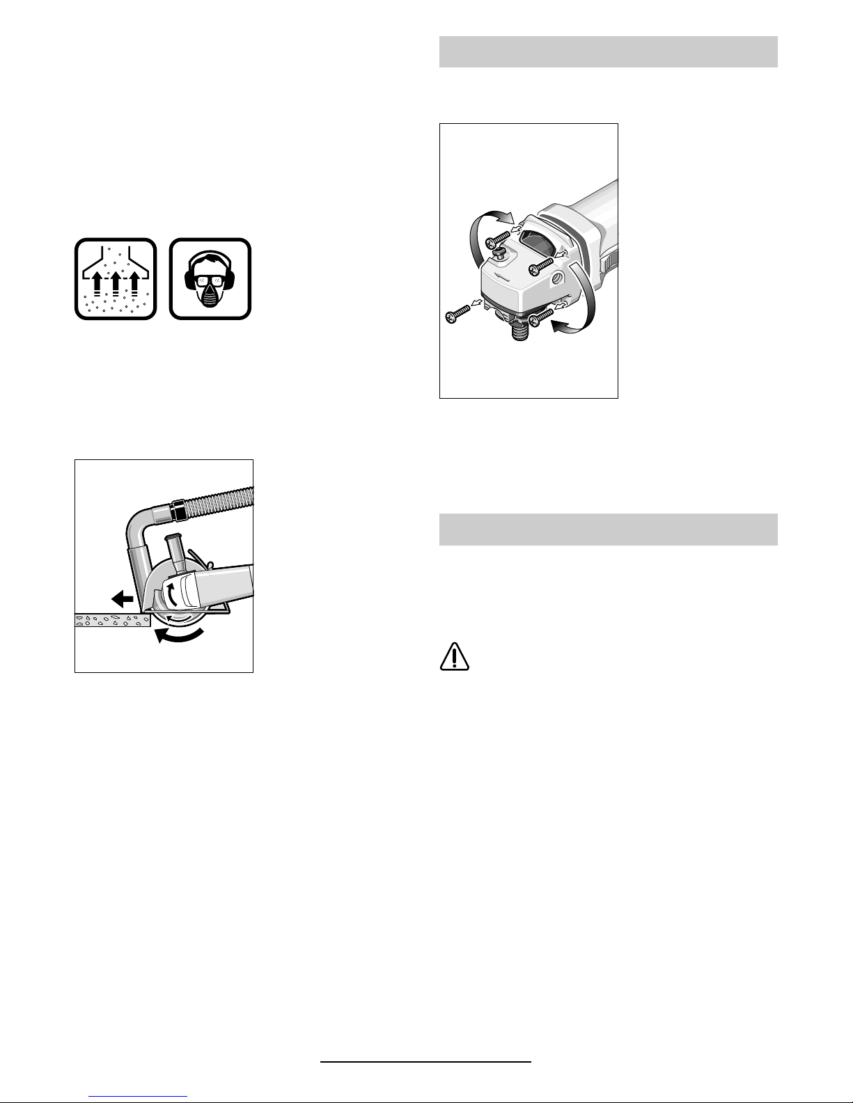
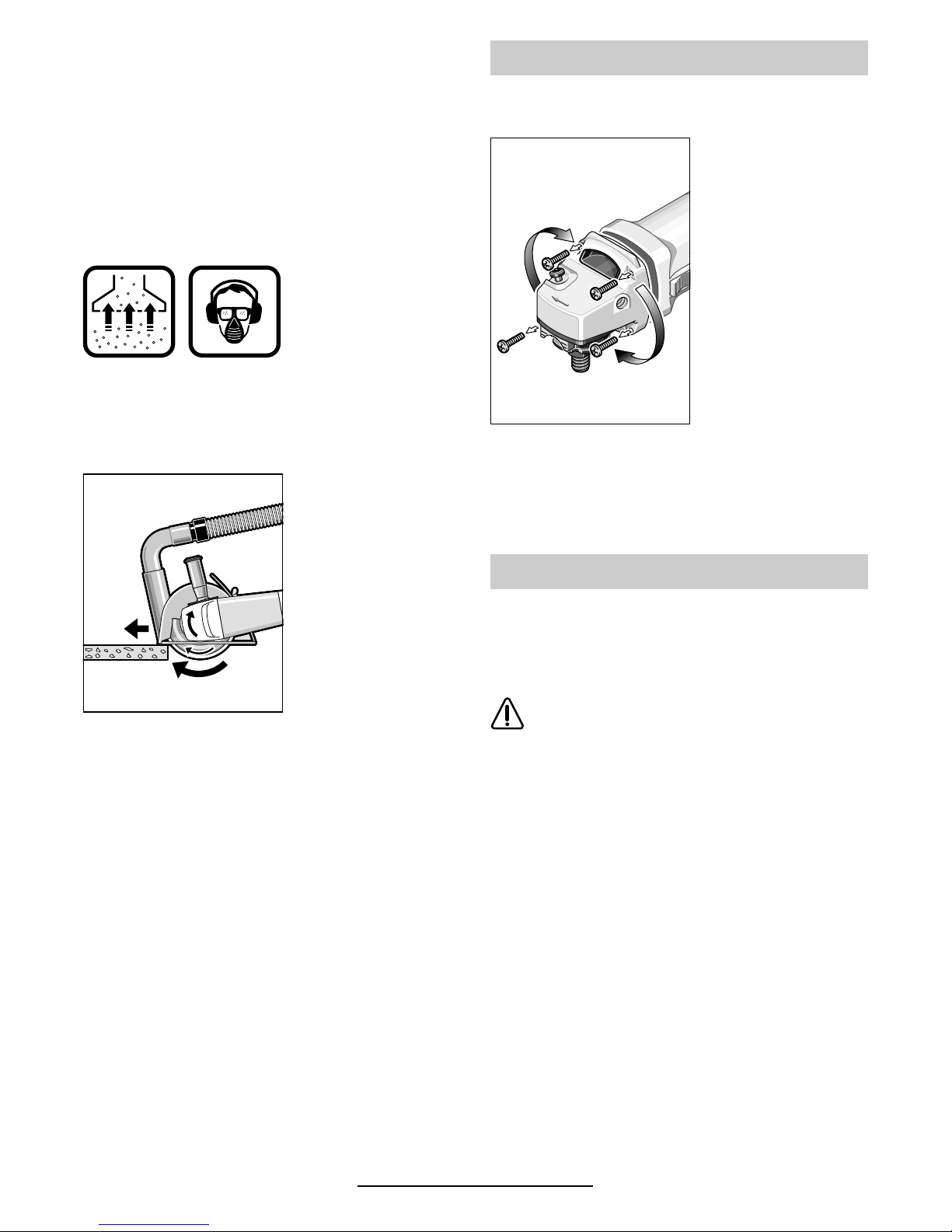
Trennen von Gestein
■ Das Gerät darf nur für Trockenschnitt/Tro-
ckenschliff verwendet werden.
Am besten eine Diamant-Trennscheibe
verwenden. Zur Sicherheit gegen Verkanten muss der
Führungsschlitten 20 mit spezieller
Absaugschutzhaube
verwendet werden.
Das Gerät darf nur mit Staubabsaugung betrieben werden. Zusätzlich Staubschutzmaske tragen.
Der Staubsauger
muss zum Absaugen
von Gesteinsstaub
zugelassen sein.
Bosch bietet geeignete Staubsauger an.
Gerät einschalten
und mit dem vorderen Teil des Führungsschlittens auf
das Werkstück setzen.
Das Gerät mit mäßigem, dem zu bearbeitenden
Material angepassten Vorschub schieben (Bild).
Beim Trennen besonders harter Werkstoffe, z. B.
Beton mit hohem Kieselgehalt, kann die Diamant-Trennscheibe überhitzen und dadurch beschädigt werden. Ein mit der Diamant-Trennscheibe umlaufender Funkenkranz weist deutlich
darauf hin.
In diesem Fall den Trennvorgang unterbrechen
und die Diamant-Trennscheibe kurze Zeit unbelastet bei Leerlaufdrehzahl abkühlen lassen.
Merklich nachlassender Arbeitsfortschritt und
umlaufender Funkenkranz sind Anzeichen für
eine stumpf gewordene Diamant-Trennscheibe.
Durch kurze Schnitte in abrasivem Material (z. B.
Kalksandstein) kann diese wieder geschärft werden.
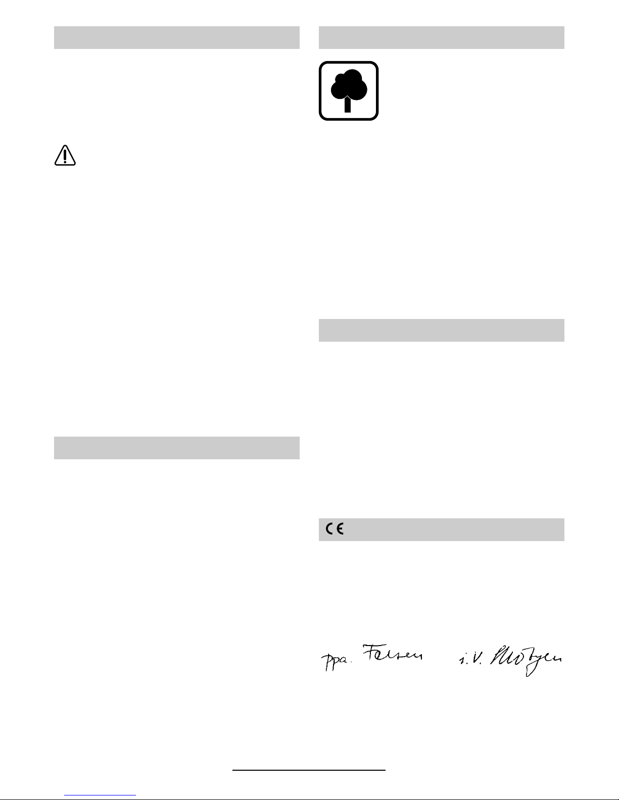
■ Vor allen Arbeiten am Gerät Netzstecker
ziehen.
Der Gerätekopf lässt
sich zum Gerätegehäuse in 90°-Schritten drehen. Dadurch
kann der Ein-/Ausschalter für besondere Arbeitsfälle in
eine günstigere
Handhabungsposition gebracht werden; z. B. für Trennarbeiten mit Führungsschlitten 20/
Trennschleifständer 17 (Zubehör)
oder für Linkshänder.
Die vier Schrauben ganz herausdrehen.
Gerätekopf vorsichtig und ohne vom Gehäuse
abzunehmen in die neue Position drehen.
Schrauben wieder eindrehen und festziehen.
■ Vor allen Arbeiten am Gerät Netzstecker
ziehen.
☞
Gerät und Lüftungsschlitze stets sauber
halten, um gut und sicher zu arbeiten.
Bei extremen Einsatzbedingungen kann
sich bei der Bearbeitung von Metallen leitfähiger Staub im Innern des Gerätes absetzen. Die Schutzisolierung des Gerätes
kann beeinträchtigt werden. Es empfiehlt
sich in solchen Fällen die Verwendung einer stationären Absauganlage, häufiges
Ausblasen der Lüftungsschlitze und das
Vorschalten eines Fehlerstrom-Schutzschalters (FI).
Sollte das Gerät trotz sorgfältiger Herstellungsund Prüfverfahren einmal ausfallen, ist die Reparatur von einer autorisierten Kundendienststelle
für Bosch-Elektrowerkzeuge ausführen zu lassen.
Bei allen Rückfragen und Ersatzteilbestellungen
bitte unbedingt die 10-stellige Bestellnummer laut
Typenschild des Gerätes angeben.
Gerätekopf drehen
Wartung und Reinigung
Deutsch - 8
1 609 929 C30 • TMS • 15.01.01
Für Bosch-Geräte leisten wir Garantie gemäß
den gesetzlichen/länderspezifischen Bestimmungen (Nachweis durch Rechnung oder Lieferschein).
Schäden, die auf natürliche Abnützung, Überlastung oder unsachgemäße Behandlung zurückzuführen sind, bleiben von der Garantie ausgeschlossen.
Beanstandungen können nur anerkannt werden,
wenn Sie das Gerät unzerlegt an den Lieferer
oder an eine Bosch-Kundendienstwerkstätte für
Druckluft- oder Elektrowerkzeuge senden.
Rohstoffrückgewinnung statt Müllentsorgung
Gerät, Zubehör und Verpackung sollten einer
umweltgerechten Wiederverwertung zugeführt
werden.
Diese Anleitung ist aus chlorfrei gefertigtem Recycling-Papier hergestellt.
Zum sortenreinen Recycling sind Kunststoffteile
gekennzeichnet.
In Deutschland sind nicht mehr gebrauchsfähige
Geräte zum Recycling beim Handel abzugeben
oder (ausreichend frankiert) direkt einzuschicken
an:
Recyclingzentrum Elektrowerkzeuge
Osteroder Landstraße 3
37589 Kalefeld
Deutschland
Robert Bosch GmbH
Servicezentrum Elektrowerkzeuge
Zur Luhne 2
D-37589 Kalefeld
✆ Service:........................................01 80 - 3 35 54 99
Fax
.......................................................... (0 55 53) 20 22 37
✆ Kundenberater: .......................01 80 - 3 33 57 99
Österreich
ABE Service GmbH
Jochen-Rindt-Straße 1
A-1232 Wien
✆ Service:...................................................(01) 61 03 80
Fax
...............................................................(01) 61 03 84 91
✆ Kundenberater:....................... (01) 7 97 22 30 20
Schweiz
Robert Bosch AG
Kundendienst Elektrowerkzeuge
Industriestrasse 31
CH-8112 Otelfingen
✆ Service:............................................. (01) 8 47 16 16
✆ Kundenberater:....... Grüne Nr. 0 800 55 11 55
Wir erklären in alleiniger Verantwortung, dass
dieses Produkt mit den folgenden Normen oder
normativen Dokumenten übereinstimmt:
EN 50 144 gemäß den Bestimmungen der Richtlinien 89/336/EWG, 98/37/EG.
Dr. Gerhard Felten Dr. Eckerhard Strötgen
Robert Bosch GmbH, Geschäftsbereich Elektrowerkzeuge
Änderungen vorbehalten
Garantie
Umweltschutz
Service und Kundenberater
Konformitätserklärung

English - 1
1 609 929 C30 • TMS • 15.01.01
1 Speed selector thumbwheel (Type CE)
2 On/Off switch
3 Auxiliary handle
4 Spindle lock
5 Grinder spindle
6 Protective guard
7 Clamping lever
8 Mounting flange with O-ring
9 Roughing/cutting disc*
10 Clamping nut
11 quick clamping nut*
12 Hand protector*
13 Rubber sanding plate*
14 Sanding sheet*
15 Round nut*
16 Cup brush*
17 Cutting grinder stand*
18 Length stop*
19 Diamond cutting disc*
20 Cutting guide with protective vacuuming
hood*
* Optional accessories
* Not all of the accessories illustrated or described are
included as standard delivery.
Tool Specifications
Angle Grinder GWS 7-115 GWS 7-125 GWS 9-125 GWS 10-125 C
Part number 0 601 800 ... 0 601 800 048 0 601 801 ... 0 601 802 ...
Rated power* 750 W 750 W 900 W 1 020 W
Output power* 450 W 450 W 520 W 600 W
No-load speed 11 000 rpm 11 000 rpm 11 000 rpm 11 000 rpm
Grinding disk dia. max. 115 mm max. 125 mm max. 125 mm max. 125 mm
Grinder spindle threads M 14 M 14 M 14 M 14
Starting current limiter – – – •
Constant electronics – – – •
Speed selection – – – –
Weight (without
optional extras) approx.
1.55 kg 1.55 kg 1.60 kg 1.60 kg
Safety class / II / II / II / II
Angle Grinder GWS 10-125 CE GWS 14-125 C GWS 14-125 CE GWS 14-150 C
Part number 0 601 803 ... 0 601 804 ... 0 601 805 ... 0 601 806 ...
Rated power* 1 020 W 1 400 W 1 400 W 1 400 W
Output power* 600 W 820 W 820 W 820 W
No-load speed 2 800 –
11 000 rpm
11 000 rpm 2 800 –
11 000 rpm
9 300 rpm
Grinding disk dia. max. 125 mm max. 125 mm max. 125 mm max. 150 mm
Grinder spindle threads M 14 M 14 M 14 M 14
Starting current limiter • • • •
Constant electronics • • • •
Speed selection • – • –
Weight (without
optional extras) approx.
1.60 kg 1.80 kg 1.80 kg 1.85 kg
Safety class / II / II / II / II
* The values given are valid for nominal voltages [U] of 230/240 V. For lower voltages and models for specific countries,
these values can vary.
Machine Elements
English - 2
1 609 929 C30 • TMS • 15.01.01
Speed Selection (Type CE)
Measured values determined according to
EN 50 144.
Typically the A-weighted noise levels of the product are: sound pressure level: 88 dB (A); sound
power level: 101 dB (A).
Wear ear protection!
The typical weighted acceleration is 5.0 m/s
2
.
When using the auxiliary handle with vibration
absorption, the hand/arm vibration of the power
tool used is typically less than 2.5 m/s
2
.
The machine is intended for cutting, roughing and
brushing metal and stone materials without using
water. For cutting stone, a cutting guide is required.
For machines with electronic control: With approved sanding tools, the machine can be used
for sanding and polishing.
Slots in load carrying walls are subject to the
Standard DIN 1053, Part 1 or country-specific
regulations.
These regulations are to be observed under all
circumstances. Before beginning work, consult
the responsible structural engineer, architects or
the construction supervisor.
Working safely with this machine is possible only when the
operating and safety information
are read completely and the instructions contained therein are
strictly followed. In addition, the
general safety instructions in the
enclosed booklet must be followed. Before using for the first
time, ask for a practical demonstration.
If the mains cable is damaged or
cut through while working, do not
touch the cable but immediately
pull the mains plug. Never use the
machine with a damaged cable.
Wear protective glasses and ear
protection.
The dust that is produced while
working can be detrimental to
health, inflammable or explosive.
Suitable safety measures are required.
Examples: Some dusts are regarded as carcinogenic. Use suitable dust-/chip extraction and wear a
dust mask.
Dust from light alloys can burn or explode. Always keep the work place clean, as blends of materials are particularly dangerous.
Wear protective gloves and sturdy
shoes.
When necessary, also wear an
apron.
Material Application Tool Thumbwheel
Plastic Polishing Lamb’s wool hood 1
Finish polishing Felt polishing disk 1
Metal Finish grinding Buffing disk 1
Removing paint Sanding sheet 2–3
Wood, Metal Brushing, Removing rust Cup brush, sanding sheet 3
Metal, Stone Grinding Grinding disk 4–6
Metal Roughing Roughing disk 6
Stone* Cutting* Cutting disk and cutting guide 6
*Cutting of stone is permitted only with the cutting guide (optional extra).
Noise/Vibration Information
Intended Use
Information Structures
For Your Safety

English - 3
1 609 929 C30 • TMS • 15.01.01
■ Connect machines that are used in the open
via a residual current device (RCD) with an actuating current of 30 mA maximum. Use only
extension cables that are approved for outdoor
use.
■ When working with the machine, always hold it
firmly with both hands and provide for a secure
stance.
■ Always direct the cable to the rear away from
the machine.
■ Always switch off the machine and allow to
come to a stop before placing it down.
■ Insert the mains plug only when the machine is
switched off.
■ For mains failure or when the main plug is
pulled, unlock the On/Off switch immediately
and turn it to the off position. This prevents uncontrolled restarting.
■ The machine must be used only for dry cutting/grinding.
■ For all work with the machine, the auxiliary
handle 3 must be mounted.
■ Hold tools by insulated gripping surfaces
when performing an operation where the
cutting tool may contact hidden wiring or
its own cord.
Contact with a “live” wire will make exposed
metal parts of the tool “live” and shock the operator.
■ For work with roughing or cutting discs, the
protective guard 6 must be mounted. For work
with the rubber sanding plate 13 or with the
cup brush 16/disc brush/flap disc, mounting
the hand protector 12 (optional extra) is rec-
ommended.
■ Use a vacuum cleaner for drawing off the dust
when working with stone. The vacuum cleaner
must be approved for masonry dust. When
cutting stone, use the cutting guide.
■ Do not work with materials containing asbestos.
■ Use only grinding tools with a permissible
speed at least as high as the no-load speed of
the machine.
■ Check grinding tools before use. The grinding
tool must be properly mounted and turn freely.
Perform a test run for at least 30 seconds without load. Do not use damaged, out-of-round or
vibrating grinding tools.
■ Protect the grinding tool from impact, shock
and grease.
■ Apply the machine to the workpiece only when
switched on.
■ Keep hands away from rotating grinding tools.
■ Pay attention to the direction of rotation. Al-
ways hold the machine so that sparks and
grinding dust fly away from the body.
■ When grinding metal, flying sparks are produced. Take care that no persons are endangered. Due to danger of fire, no combustible
materials should be located in the vicinity
(spark flight zone).
■ Be careful when cutting grooves, e. g. in loadcarrying walls: See information on structures.
■ Do not drill, fasten or cut into blind areas
where electric, gas or water lines may exist.
Use appropriate detectors to determine if
these lines are hidden in the work area or
call the local utility company for assistance.
Contacting electric lines may cause fire or
electric shock. Striking a gas line will probably
result in explosion. Breaking into a water pipe
will cause property damage or may cause an
electric shock.
■ Blocking the cutting disc leads to jerking reaction forces on the machine. In this case switch
off the machine immediately.
■ Pay attention to the dimensions of the grinding
disc. The mounting hole diameter must fit the
mounting flange 8 without play. Do not use reducer pieces or adapters.
■ Never use cutting discs for rough grinding. Do
not exert any lateral pressure on the cutting
discs.
■ Observe the manufacturer’s instructions for
mounting and using grinding tools.
■ Caution! The grinding tool runs on after the
machine is switched off.
■ Do not clamp the machine in a vice.
■ Never allow children to use the machine.
■ Bosch is only able to ensure perfect function-
ing of the machine if the original accessories
intended for it are used.
English - 4
1 609 929 C30 • TMS • 15.01.01
■ Before any work on the machine itself, pull
the mains plug.
Protective Guard
■ For work with roughing or cutting discs,
the protective guard 6 must be mounted.
Open the clamping lever 7.
Place the protective guard 6
with coded cams into the respectively coded grooves on
the spindle collar of the machine head and turn anticlockwise to the required position (working position).
To fasten the protective
guard 6, close the clamping
lever 7.
The closed side of the protective guard 6 must always
point to the operator.
Note: Coded notches on the protective guard 6
ensure that only a protective guard that fits the
machine type can be mounted.
Disassemble in the reverse sequence.
Auxiliary Handle
■ For all work with the machine, the auxiliary
handle 3 must be mounted.
Screw the auxiliary handle 3 on the right or left of
the machine head depending on the working
method.
Auxiliary handle with vibration
absorption (Optional extra)
Do not make any alterations to the auxiliary handle.
Do not continue to use an auxiliary handle if it is
damaged.
Hand Protector (Optional extra)
For work with the rubber sanding plate 13 or with
the cup brush 16/disc brush/flap disc, mounting
the hand protector 12 (optional extra) is recom-
mended. The hand protector 12 is fastened with
the auxiliary handle 3.
■ Before any work on the machine itself, pull
the mains plug.
Use only grinding tools with a permissible speed at least as high as the no-load
speed of the machine.
Roughing and cutting discs become
very hot while working; do not touch until they have cooled.
■ Clean the grinder spindle and all parts to be
mounted. For clamping and loosening the
grinding tools, lock the grinder spindle 5 with
the spindle locking button 4.
Actuate the spindle locking button 4 only
when the grinder spindle is at a standstill!
Roughing/Cutting Disk
■ Pay attention to the dimensions of the grinding
disc. The mounting hole diameter must fit the
mounting flange 8 without play. Do not use reducer pieces or adapters.
When using a diamond cutting disk, take care
that the direction of rotation arrow on the diamond cutting disk and the direction of rotation of
the machine (direction of rotation arrow on the
machine head) agree.
For mounting, see the illustration page.
Screw on the clamping nut 10 and tighten with
the two-hole spanner (see Section “Quick Clamping Nut”).
An O-ring (plastic
part) is inserted in
the retainer flange 8
around the spigot.
If the O-ring is missing or is damaged, it must
in all cases be replaced (Order No.
1 600 210 039) before the retainer flange 8 is
mounted.
☞
After mounting the grinding tool and before switching on, check that the grinding tool is correctly mounted and that it
can turn freely.
Mounting the
Protective Devices
6
7
Mounting the Grinding Tools
(Optional Accessories)
8
English - 5
1 609 929 C30 • TMS • 15.01.01
Flap disc
Remove the protective guard 6 and mount the
hand protector 12. Place the special retainer
flange 8 (optional extra, Order No.
2 605 703 028) and the flap disc on the grinder
spindle 5 . Screw on the clamping nut 10 and
tighten with the two-hole spanner.
Rubber Sanding Plate 13
Remove the protective guard 6 and mount the
hand protector 12.
For mounting, see the illustration page.
Screw on the round nut 15 and tighten with the
two-hole spanner.
Cup Brush 16/Disc brush
Remove the protective guard 6 and mount the
hand protector 12.
The grinding tool must be able to be screwed
onto the grinding spindle 5 until it rests firmly
against the grinder spindle flange at the end of
the grinder spindle threads. Tighten with an
open-ended spanner.
All grinding tools described in these operating instructions can be used (roughing and cutting
discs of synthetic resin-bonded, fibre-reinforced
material).
The permissible speed [rpm] or the circumferential speed [m/s] of the grinding tools used must be
at least in accordance with the values given in the
table.
Therefore, always observe the permissible rota-
tional/circumferential speed on the label of the
grinding tool.
Instead of the clamping nut 10, the quick clamping nut 11 (optional extra) can be used. Grinding
tools can be mounted without using tools.
The quick clamping nut 11 may be used only
for roughing and cutting discs.
Use only a flawless, undamaged quick clamping nut 11.
When screwing on, take care that the side with
printing does not point to the grinding disc. The
arrow must point to the index mark 21.
Lock the grinder
spindle with the spindle locking button 4.
Tighten the quick
clamping nut by
forcefully turning the
grinding disc in the
clockwise direction.
A properly tightened
undamaged, quick
clamping nut can be
loosened by hand
turning the knurled
ring in the counterclockwise direction.
Never loosen a tight
quick clamping nut
with pliers but use a
two-hole spanner.
Insert the two-hole
spanner as shown in
the illustration.
Approved Grinding Tools
max.
[mm] [mm]
Dbd[rpm] [m/s]
115
125
150
6
6
6
22.2
22.2
22.2
11 000
11 000
9 300
80
80
80
115
125––
––11 000
11 0008080
75 30 M 14 11 000 45
b
d
D
D
D
b
d
Quick Clamping Nut
(Optional Extra)
4
21
11
4
English - 6
1 609 929 C30 • TMS • 15.01.01
Check for correct mains voltage: The voltage
of the power source must agree with the voltage
specified on the nameplate of the machine.
Equipment marked with 230 V can also be connected to 220 V.
Switching on: Slide the On/Off switch 2
forward.
Switching off: Release the On/Off switch 2.
Locking: Slide the On/Off switch 2 for-
ward and press down to the
front until it latches.
Switching off: Press down the On/Off switch 2
to the rear - the switch springs
to the off position.
☞
Test run!
Check the grinding tool before use. The
grinding tool must be flawlessly mounted
and be able to rotate freely. Perform a test
run of at least 30 seconds without load. Do
not use damaged, out-of-round or vibrating
grinding tools.
Starting Current Limiting (Type C/CE)
As a result of soft starting, a 13-A fuse is adequate.
A machine without starting current-limiter requires a higher fuse protection.
Constant Electronics (Type C/CE)
The constant speed electronics hold the speed at
no-load and when under load nearly constant and
ensure uniform working performance.
Overload Protection
When overloaded, the motor comes to a stop.
Relieve the load on the machine immediately and
allow to cool for approx. 30 seconds at the highest no-load speed.
Preselect the required speed using the thumb
wheel 1 according to the table following the sec-
tion “Product Specification” (reference values).
■ Clamp the workpiece if it does not remain
stationary due to its own weight.
■ Do not load the machine so heavily that it
comes to a standstill.
■ Roughing and cutting discs become very
hot while working; do not touch until they
have cooled.
Rough Grinding
With an approach angle of 30° to
40°, the best roughing results can
be achieved. Move the machine
back and forth with moderate pressure. In this manner, the work piece
will not become too hot, does not
discolour and no ridges are formed.
Never use a cutting disc for roughing.
Flap disc
With the flap disc (optional extra), curved surfaces and profiles (contour sanding) can be
worked.
Flap discs have a considerably higher service life
than sanding sheets, lower noise level and lower
sanding temperatures.
Cutting
When cutting, do not press, tilt or
oscillate. Work with moderate advancing that is adapted to the material being worked.
Do not brake coasting cutting disks
with side pressure.
Important is the direction in which cutting is performed.
The machine must
always work opposite
to the direction of rotation. Therefore,
never move the machine in the other direction! Otherwise,
the danger exists of it
being pushed un-
controlled out of the
cut.
Initial Operation
Speed Selection (Type CE)
Operating Instructions
English - 7
1 609 929 C30 • TMS • 15.01.01
Cutting grinder Stand
With the cutting grinder stand 17 (optional extra),
work pieces of the same length can be cut at angles of 0 to 45°.
When cutting profiles and square pipes, it is best
to start with the smallest cross section.
Cutting Stone
■ The machine must be used only for dry cut-
ting/grinding.
It is best to work with
a diamond cutting
disc. To ensure
against tilting, the
cutting guide 20
with special protective vacuuming hood
must be used.
The machine must be operated only with dust extraction. In addition, wear a dust mask.
The vacuum cleaner
must be approved for
the extraction of masonry dust.
Bosch provides suitable vacuum cleaners.
Switch on the machine and place the
front part of the cutting guide on the
workpiece.
Slide the machine with moderate advancing that
is adapted to the material to be worked (Figure).
For cutting especially hard material, e. g., concrete with high gravel content, the diamond cutting disc can overheat and become damaged as
a result. This is indicated clearly by a ring of
sparks that rotates with the diamond cutting disc.
In this case, interrupt the cutting process and allow the diamond cutting disc to cool by running
frely at no-load speed for a short time.
Noticeable decreasing work progress and a rotating spark ring are indications of a diamond cutting
disc that has become dull. With brief cuts in an
abrasive material (e. g., chalky sand stone), it
can be sharpened again.
■ Before any work on the machine itself, pull
the mains plug.
The machine head
can be rotated with respect to the machine
housing in 90° steps.
In this manner, the
on/off switch can be
brought to an advantageous handling position for special working situations, e. g.,
for cutting work with
the cutting guide 20/
cut-off stand 17 (op-
tional extra) or for left-
handed persons.
Unscrew completely the four screws.
Rotate the machine head carefully and without
removing from the housing to the new position.
Screw in the screws again and tighten.
■ Before any work on the machine itself, pull
the mains plug.
☞
For safe and proper working, always keep
the machine and the ventilation slots clean.
In extreme working conditions, conductive
dust can accumulate in the interior of the
machine when working with metal. The
protective insulation of the machine can be
degraded. The use of a stationary extraction system is recommended in such cases
as well as frequently blowing out the ventilation slots and installing a residual current
device (RCD).
If the machine should fail despite the rigorous
manufacturing and testing procedures, repair
should be carried out by an authorised after-sales
service centre for Bosch power tools.
In all correspondence and spare parts orders,
please always include the 10-digit order number
given on the nameplate of the machine.
Rotating the Machine Head
Maintenance and Cleaning
English - 8
1 609 929 C30 • TMS • 15.01.01
We guarantee Bosch appliances in accordance
with statutory/country-specific regulations (proof
of purchase by invoice or delivery note).
Damage attributable to normal wear and tear,
overload or improper handling will be excluded
from the guarantee.
In case of complaint please send the machine,
undismantled, to your dealer or the Bosch Service Centre for electric power tools.
Recycle raw materials instead of disposing as
waste.
The machine, accessories and packaging should
be sorted for environmental-friendly recycling.
These instructions are printed on recycled paper
manufactured without chlorine.
The plastic components are labelled for categorized recycling.
Great Britain
Robert Bosch Ltd. (B.S.C.)
P.O. Box 98
Broadwater Park
North Orbital Road
Denham-Uxbridge
GB-Middlesex UB 9 5HJ
✆ Service........................................ (0 18 95) 83 87 82
✆ Advice line................................ (0 18 95) 83 87 91
Fax
......................................................... (0 18 95) 83 87 89
Ireland
Beaver Distribution Ltd.
Greenhills Road
IRL-Tallaght-Dublin 24
✆ Service................................................. (01) 45 15 211
Fax
.................................................................. (01) 45 17 127
Australia
Robert Bosch Australia L.t.d.
RBAU/SPT2
1555 Centre Road
P.O. Box 66 Clayton
AUS-3168 Clayton/Victoria
✆ .................................................................. 1 800 804 777
Fax
.................................................................. 1 800 819 520
CustomerSupportSPT@au.bosch.com
www.bosch.com.au
New Zealand
Robert Bosch Limited
14-16 Constellation Drive
Mairangi Bay
Auckland
New Zealand
✆ .................................................................. (09) 47 86 158
Fax
.................................................................. (09) 47 82 914
We declare under our sole responsibility that this
product is in conformity with the following standards or standardisation documents: EN 50 144
according to the provisions of the directives
89/336/EEC, 98/37/EC.
Dr. Gerhard Felten Dr. Eckerhard Strötgen
Robert Bosch GmbH, Geschäftsbereich Elektrowerkzeuge
Subject to change without notice
Guarantee
Environmental Protection
Service and Customer Assistance
Declaration of Conformity

Po polsku - 1
1 609 929 C30 • TMS • 15.01.01
1 Regulator nastawczy wst™pnego wyboru
pr™dko∂ci obrotowej (Typ CE)
2 Wƌcznik/wyƌcznik
3 Uchwyt dodatkowy
4 Przycisk blokady wrzeciona
5 Wrzeciono szlifierki
6 Os¬ona tarczy
7 DΩwignia mocujåca
8 Ko¬nierz mocujåcy z pier∂cieniem typu O
9 Tarcza szlifierska/tnåca*
10 ƒruba mocujåca
11 Szybkozaciskowa ∂ruba mocujåca *
12 Os¬ona ræki*
13 Gumowa tarcza szlifierska*
14 Ok¬adzina szlifierska*
15 Nakrætka okråg¬a*
16 Szczotka garnkowa*
17 Stø¬ do ciæcia*
18 Prowadnica wzd¬u†na*
19 Diamentowa tarcza tnåca*
20 Prowadnica saneczkowa z pokrywå
odsysajåcå*
* Osprz™t dodatkowy
* Opisany lub przedstawiony osprz™t nie nale†y
w ca∆o∂ci do wyposa†enia standardowego
elektronarz™dzia.
Dane techniczne
Szlifierka kåtowa GWS 7-115 GWS 7-125 GWS 9-125 GWS 10-125 C
Numer katalogowy 0 601 800 ... 0 601 800 048 0 601 801 ... 0 601 802 ...
Moc nominalna* 750 W 750 W 900 W 1 020 W
Moc wyj∂ciowa* 450 W 450 W 520 W 600 W
Pr™dko∂ç obrotowa
bez obciå†enia
11 000 min
-1
11 000 min
-1
11 000 min
-1
11 000 min
-1
Ø tarczy szlifierskiej max. 115 mm max. 125 mm max. 125 mm max. 125 mm
Gwint wrzeciona tarczy M 14 M 14 M 14 M 14
Ograniczenie prådu
rozruchowego
– – – •
System Constant-Electronic – – – •
Wst∑pny wybør pr∑dko∂ci
obrotowej
– – – –
Ci™†ar
(bez wyposa†enia) ok.
1,55 kg 1,55 kg 1,60 kg 1,60 kg
Klasa ochrony / II / II / II / II
Szlifierka kåtowa GWS 10-125 CE GWS 14-125 C GWS 14-125 CE GWS 14-150 C
Numer katalogowy 0 601 803 ... 0 601 804 ... 0 601 805 ... 0 601 806 ...
Moc nominalna* 1 020 W 1 400 W 1 400 W 1 400 W
Moc wyj∂ciowa* 600 W 820 W 820 W 820 W
Pr™dko∂ç obrotowa
bez obciå†enia
2 800 –
11 000 min
-1
11 000 min
-1
2 800 –
11 000 min
-1
9 300 min
-1
Ø tarczy szlifierskiej max. 125 mm max. 125 mm max. 125 mm max. 150 mm
Gwint wrzeciona tarczy M 14 M 14 M 14 M 14
Ograniczenie prådu
rozruchowego
• • • •
System Constant-Electronic • • • •
Wst∑pny wybør pr∑dko∂ci
obrotowej
• – • –
Ci™†ar
(bez wyposa†enia) ok.
1,60 kg 1,80 kg 1,80 kg 1,85 kg
Klasa ochrony / II / II / II / II
* Dane wa†ne dla napi™ç [U] 230/240 V. Przy ni†szych napi™ciach i w wersjach specjalnych dla ró†nych krajów warto∂ci te
mogå si™ zmieniaç.
Elementy urzådzenia
Po polsku - 2
1 609 929 C30 • TMS • 15.01.01
Wst™pny wybór pr™dko∂ci obrotowej (Typ CE)
Warto∂ci pomiarowe wyznaczone zgodnie
z EN 50 144.
Zmierzony poziom ha∆asu urzådzenia jest
typowy: poziom ci∂nienia akustycznego wynosi
88 dB (A); poziom mocy akustycznej wynosi
101 dB (A).
Stosowaç ∂rodki ochrony s∆uchu!
Wyznaczone przyspieszenie wynosi 5,0 m/s
2
.
W czasie stosowania uchwytu dodatkowego
z pow∆okå antywibracyjnå wibracje na linii
r™ka-rami™ stosowanego elektronarz™dzia så
typowo mniejsze ni† 2,5 m/s
2
.
Urzådzenie jest przeznaczone do ci™cia,
zdzierania i szczotkowania metali i materia∆ów
kamiennych bez zastosowania wody. Do ci™cia
kamienia stosowaç obowiåzkowo prowadnic™
saneczkowå.
Dotyczy urzådzeµ ze sterowaniem
elektronicznym: z dopuszczonymi narz™dziami
szlifierskimi mo†na stosowaç elektronarz™dzie
do wykonywania prac szlifierskich i polerskich.
Wynonywanie szczelin w ∂cianach no∂nych
podlega normie DIN 1053 cz™∂ç 1 lub
miejscowym przepisom i ustaleniom.
Nale†y ∂ci∂le stosowaç si™ do tych przepisów.
Przed rozpocz™ciem pracy zasi™gnåç opinii
odpowiedzialnego za konstrukcj™ statyka,
architekta lub kierownictwa budowy.
Bezpieczna i wydajna praca przy
u†yciu tego urzådzenia mo†liwa
jest po uwa†nym zapoznaniu si™
z niniejszå instrukcjå obs∆ugi
oraz ∂cis∆ym przestrzeganiem
wskazówek bezpieczeµstwa.
Dodatkowo nale†y zapoznaç si™
z ogólnymi wskazówkami
bezpieczeµstwa za∆åczonymi do
niniejszej instrukcji. Przed
pierwszym u†yciem urzådzenia
odbyç odpowiedni instrukta†
praktyczny.
Je∂li w czasie pracy dojdzie do
uszkodzenia lub przeci™cia kabla
zasilajåcego - nie dotykaç go.
Natychmiast wyciågnåç wtyczk™
z gniazdka. Nigdy nie pracowaç
urzådzeniem z uszkodzonym
kablem zasilajåcym.
Stosowaç okulary ochronne i ∂rodki
ochrony s∆uchu.
Materia∆ Zastosowanie Narz∑dzie Zakres pr∑dko∂ci
na regulatorze
Tworzywa sztuczne Polerowanie Pokrywa z we∆ny jagni∑cej 1
Szlif delikatny Filcowa tarcza polerska 1
Metale Szlif delikatny Wielowarstwowa p∆øcienna
tarcza polerska
1
Usuwanie farby Tarcza szlifierska 2–3
Drewno, metal Szczotkowanie,
odrdzewianie
Szczotka garnkowa,
tarcza szlifierska
3
Metal, kamieµ Szlifowanie Tarcza szlifierska 4–6
Metal Zdzieranie Tarcza zdzierajåca 6
Kamieµ* Ci∑cie* Tarcza tnåca z prowadnicå 6
*Ci∑cie kamieni dozwolone jest wy∆åcznie razem z prowadnicå saneczkowå (osprz∑t dodatkowy).
Informacja na temat ha∆asu i wibracji
U†ytkowanie zgodnie
z przeznaczeniem
Wskazówki dotyczåce statyki budowli
Zasady bezpieczeµstwa
Po polsku - 3
1 609 929 C30 • TMS • 15.01.01
Powstajåce w czasie pracy py∆y
mogå byç niebezpieczne dla
zdrowia, palne lub wybuchowe.
Niezb™dne jest stosowanie
odpowiednich ∂rodków
zabezpieczajåcych.
Na przyk∆ad: Niektóre py∆y så
rakotwórcze. Stosowaç
odpowiednie systemy odsysania
wiórów/py∆ów szlifierskich i
zak∆adaç mask™ przeciwpy∆owå.
Py∆y powstajåce przy obróbce metali lekkich så
∆atwopalne i wybuchowe. Utrzymywaç miejsce
pracy ca∆y czas w porzådku i czysto∂ci, poniewa†
mieszanki metali så szczególnie niebezpieczne.
Stosowaç r™kawice ochronne
i odpowiednie obuwie robocze.
Je∂li to konieczne, na∆o†yç równie†
fartuch ochronny.
■ Urzådzenia pracujåce na wolnym powietrzu
przy∆åczaç poprzez ochronny wy∆åcznik
prådowy (FI) o maksymalnym prådzie
wy∆åczajåcym 30 mA. Stosowaç wy∆åcznie
przeznaczone do pracy na zewnåtrz kable
przed∆u†ajåce.
■ W czasie pracy trzymaç mocno urzådzenie
w obu d∆oniach i przyjåç bezpiecznå pozycj™
roboczå.
■ Kabel zasilajåcy prowadziç zawsze za
urzådzeniem.
■ Przed od∆o†eniem wy∆åczyç urzådzenie
i pozwoliç na swobodny wybieg.
■ Wtyczk™ wk∆adaç do gniazdka sieciowego
tylko przy wy∆åczonym urzådzeniu.
■ W przypadku przerwania dop∆ywu prådu lub
wyciågni™cia wtyczki z gniazdka, natychmiast
odblokowaç przycisk w∆åcznika/wy∆åcznika
i pozwoliç mu na powrót do pozycji wyj∂ciowej.
Zapobiega to niekontrolowanemu ponownemu
rozruchowi urzådzenia.
■ Urzådzenie jest przeznaczone wy∆åcznie do
szlifu/ci∑cia na sucho.
■ Ze wzgl™dów bezpieczeµstwa zawsze
stosowaç uchwyt dodatkowy 3.
■ Elektronarz™dzie chwytaç tylko za
izolowane uchwyty, je∂li narz™dzie robocze
mia∆oby trafiç w ukryty przewód
instalacyjny lub w∆asny kabel zasilajåcy.
Kontakt z przewodem napi™ciowym mo†e
spowodowaç, †e metalowe cz™∂ci
elektronarz™dzia znajdå si™ pod napi™ciem
i spowodujå pora†enie elektryczne
obs∆ugujåcego.
■ Przy pracach z wykorzystaniem tarcz
zdzierajåcych/rozcinajåcych zamocowaç
pokryw™ ochronnå 6. Przy pracach tarczami
gumowymi 13 lub szczotkami garnkowymi 16/
szczotkami tarczowymi nale†y zamocowaç
os∆on™ r™ki 12 (osprz™t dodatkowy).
■ W czasie obróbki kamienia stosowaç system
odsysania pyƗw. Podƌczany odkurzacz musi
posiadaç atest dopuszczeniowy do odsysania
py∆ów kamiennych. Do ci™cia kamienia
stosowaç prowadnic™ saneczkowå.
■ Materia∆y zawierajåce azbest nie mogå byç
obrabiane.
■ Stosowaç wy∆åcznie narz™dzia szlifierskie,
których dopuszczalna pr™dko∂ç obrotowa jest
co najmniej tak wysoka jak pr™dko∂ç obrotowa
urzådzenia na biegu bez obciå†enia.
■ Przed w∆åczeniem urzådzenia sprawdziç, czy
narz™dzie zosta∆o prawid∆owo zamontowane
i czy mo†e si™ swobodnie obracaç.
Przeprowadziç próbny rozruch przez co
najmniej 30 sekund bez obciå†enia na biegu
ja∆owym. Uszkodzone, nieokråg∆e lub
wibrujåce narz™dzia szlifierskie nie mogå byç
stosowane.
■ Chroniç narz∑dzia przed upadkami,
uderzeniami i smarami.
■ Prowadziç urzådzenie do obrabianego
elementu w stanie wƌczonym.
■ Nie zbli†aç d∆oni do obracajåcych si™ narz™dzi
szlifierskich.
■ Uwa†aç na kierunek padania iskier.
Utrzymywaç szlifierk∑ zawsze w takiej pozycji,
aby iskry i py∆ szlifierski nie pada∆y na
obs∆ugujåcego.
■ W czasie szlifowania metali powstaje snop
iskier. Nale†y uwa†aç, aby nie by∆y nim
zagro†one osoby znajdujåce si∑ w pobli†u
pracy szlifierki. Ze wzgl∑døw bezpieczeµstwa
nie wolno przechowywaç w miejscu pracy
szlifierki (w zasi∑gu padania snopu iskier)
†adnych materia∆øw ∆atwopalnych.
■ Uwaga przy wykonywaniu szczelin i otworów
np. w ∂cianach no∂nych: patrz wskazówki
statyka.
Po polsku - 4
1 609 929 C30 • TMS • 15.01.01
■ Nie wierciç, nie ciåç i nie pi∆owaç
w obszarach, w których mogå przebiegaç
przewody elektryczne, gazowe lub
wodociågowe. Stosowaç odpowiednie
przyrzådy wykrywajåce w celu lokalizacji
takich instalacji lub zasi™gnåç pomocy
odpowiedniego miejscowego
przedsi™biostwa zasilajåcego.
Kontakt z przewodami elektrycznymi mo†e
doprowadziç do wybuchu ognia lub
pora†enia.Uszkodzenia instalacji gazowej
mogå prowadziç do wybuchu. Uszkodzenia
instalacji wodnej mogå doprowadziç do
powstania szkód lub pora†enia elektrycznego.
■ Zablokowanie tarczy tnåcej prowadzi do
gwa∆townej reakcji zwrotnej urzådzenia.
W takim przypadku natychmiast wy∆åczyç
urzådzenie.
■ Otwør podk∆adki 8 musi idealnie bez
jakichkolwiek luzøw pasowaç w otwør tarczy
szlifierskiej/tnåcej. Nie stosowaç podk∆adek
redukcyjnych lub adapterøw.
■ Nie hamowaç wybiegu obracajåcych si∑
narz∑dzi poprzez boczne dociskanie
urzådzeniem do innych przedmiotøw.
■ Przy monta†u i stosowaniu oprzyrzådowania
szlifierskiego przestrzegaç wskazøwek
producenta.
■ Pami∑taç o tym, †e po wy∆åczeniu urzådzenia
tarcza szlifierska obraca si∑ jeszcze.
■ Nie mocowaç urzådzenia w imadle.
■ W †adnym przypadku urzådzenia nie mogå
obs∆ugiwaç dzieci.
■ Firma Bosch zapewnia bezawaryjne
funkcjonowanie elektronarz™dzia tylko
w przypadku stosowania oryginalnego
oprzyrzådowania.
■ Przed przyståpieniem do jakichkolwiek
czynno∂ci przy urzådzeniu wyciågnåç
wtyczk™ z gniazdka.
Os¬ona tarczy
■ Przy pracach z wykorzystaniem tarcz
zdzierajåcych/rozcinajåcych zamocowaç
pokryw™ ochronnå 6.
Otworzyç dΩwigni™
mocujåcå 7.
Nasadziç pokryw™
ochronnå 6 z kodowym
noskiem wpustowym na
ko∆nierz wrzeciona g∆owicy
urzådzenia i obróciç
w †ådanå pozycj™ roboczå
(pozycj™ pracy).
W celu unieruchomienia
pokrywy ochronnej 6
zamknåç dΩwigni™
mocujåcå 7.
Zamkniæta strona os¬ony
tarczy 6 musi zawsze
wskazywaç na
obs¬ugujåcego.
Wskazøwka: Os¬ona tarczy 6 posiada wypust
kodujåcy umo†liwiajåcy zamontowanie tylko
odpowiedniej do danego typu urzådzenia os¬ony.
Demonta† nast™puje w odwrotnej kolejno∂ci.
Uchwyt dodatkowy
■ Ze wzgl™dów bezpieczeµstwa zawsze
stosowaç uchwyt dodatkowy 3.
Uchwyt dodatkowy 3 wkræciç w g¬owicæ
urzådzenia po lewej lub prawej stronie,
w zale†no∂ci od wymagaµ roboczych.
Uchwyt dodatkowy z t∆umieniem
wibracji (osprz™t dodatkowy)
Nie wykonywaç jakichkolwiek zmian
w uchwycie dodatkowym.
Nie u†ywaç uszkodzonego uchwytu
dodatkowego.
Monta† elementøw
zabezpieczajåcych
6
7
Po polsku - 5
1 609 929 C30 • TMS • 15.01.01
Os∆ona r™ki (osprz™t dodatkowy)
Przy pracach tarczami gumowymi 13 lub
szczotkami garnkowymi 16/szczotkami
tarczowymi nale†y zamocowaç os∆on™ r™ki 12
(osprz™t dodatkowy). Os∆ona r™ki 12 mocowana
jest wspólnie z uchwytem dodatkowym 3.
■ Przed przyståpieniem do jakichkolwiek
czynno∂ci przy urzådzeniu wyciågnåç
wtyczk™ z gniazdka.
Stosowaç wy∆åcznie narz™dzia
szlifierskie, których dopuszczalna
pr™dko∂ç obrotowa jest co najmniej tak
wysoka jak pr™dko∂ç obrotowa
urzådzenia na biegu bez obciå†enia.
Tarcze zdzierajåce i tnåce rozgrzewajå
sie w czasie pracy do wysokich
temperatur; nie dotykaç przed
ostygni™ciem.
■ Przed monta†em oczy∂ciç wrzeciono
szlifierskie i wszystkie elementy. W celu
dociågni™cia lub zwolnienia narz™dzi
szlifierskich ustaliç po∆o†enie wrzeciona 5
za pomocå przycisku blokady wrzeciona 4.
Przycisk blokady wrzeciona 4 obs∆ugiwaç
wyƌcznie przy nieruchomym wrzecionie!
Tarcze zdzierajåce/tnåce
■ Otwør podk∆adki 8 musi idealnie bez
jakichkolwiek luzøw pasowaç w otwør tarczy
szlifierskiej/tnåcej. Nie stosowaç podk∆adek
redukcyjnych lub adapterøw.
Przy mocowaniu diamentowej tarczy tnåcej
uwa†aç, aby strza∆ki kierunku obrotu na tarczy
diamentowej i szlifierce (strza∆ka kierunku
obrotów na g∆owicy urzådzenia) pokrywa∆y si™.
Monta† patrz szkic.
Nakr™tk™ mocujåcå 10 nakr™ciç i dociågnåç za
pomocå klucza dwuczopowego (patrz rozdzia∆
„ƒruba szybkomocujåca“).
W ko¬nierzu
mocujåcym 8
zamontowany jest
pier∂cieµ typu O
(cz™∂ç z tworzywa
sztucznego).
W przypadku stwierdzenia jego braku lub
uszkodzenia bezwzgl™dnie wymieniç lub
uzupe¬niç, zanimponownie zamontujemy
ko¬nierz 8 (numer katalogowy pier∂cienia
1 600 210 039).
☞
Po zamontowaniu narz™dzia
szlifierskiego i przed wƌczeniem
urzådzenia sprawdziç, czy narz™dzie
zosta∆o prawid∆owo zamontowane
i czy mo†e si™ swobodnie obracaç.
Tarcze ∂cierne MOP
Zdjåç pokryw∑ ochronnå 6 i zamontowaç os∆on∑
r∑ki 12. Osadziç specjalnå podk∆adk™ 8 (osprz∑t
dodatkowy numer katalogowy pier∂cienia
2 605 703 028) oraz tarcz™ na wrzecionie 5
i zamocowaç przy u†yciu nakr™tki mocujåcej 10.
Gumowy talerz szlifierski 13
Zdjåç pokryw∑ ochronnå 6 i zamontowaç os∆on∑
r∑ki 12.
Monta† patrz szkic.
Zakr∑ciç nakr∑tk∑ okråg∆å 15 i dociågnåç jå za
pomocå klucza dwuczopowego.
Szczotki garnkowe 16/
Szczotki tarczowe
Zdjåç pokryw∑ ochronnå 6 i zamontowaç os∆on∑
r∑ki 12.
Szczotk∑ garnkowå nakr∑ciç bezpo∂rednio na
wrzeciono 5 i dociågnåç przy u†yciu klucza
wide∆kowego. Wrzeciono szlifierki musi zostaç
ca∆kowicie wkr∑cone w korpus narz∑dzia
szlifierskiego. Narz∑dzie szlifierskie musi
przylegac dok∆adnie do ko∆nierza wrzeciona
szlifierki.
Monta† narz∑dzi szlifierskich
(osprz∑t dodatkowy)
8
Po polsku - 6
1 609 929 C30 • TMS • 15.01.01
Stosowaç mo†na wy∆åcznie wymienione
w niniejszej instrukcji narz™dzia szlifierskie
(tarcze zdzierajåce i tnåce spajane †ywicami
syntetycznymi i zbrojone w∆óknem).
Dopuszczalna pr™dko∂ç obrotowa [min
-1
]
wzgl. pr™dko∂ç obwodowa [m/s] zastosowanych
narz™dzi szlifierskich musi odpowiadaç co
najmniej warto∂ciom podanym w tabeli.
Przestrzegaç dopuszczalnych pr™dko∂ci
obrotowych/obwodowych umieszczonych na
etykiecie kontrolnej narz™dzia szlifierskiego.
Zamiast zwyk∆ej ∂ruby mocujåcej 10 do
monta†u narz™dzi mo†na stosowaç ∂rub™
szybkomocujåcå 11 (osprz™t dodatkowy).
W ten sposób monta† narz™dzi szlifierskich
przebiega bez dodatkowego klucza.
ƒruba szybkomocujåca 11 mo†e byç
stosowana wyƌcznie do mocowania tarcz
zdzierajåcych i tnåcych.
Stosowaç wy∆åcznie nieuszkodzonå ∂rub™
szybkomocujåcå 11.
W czasie monta†u przestrzegaç: Strza∆ka na
gørnej powierzchni musi wskazywaç pole
indeksowe 21 (patrz szkic).
Ustaliç po∆o†enie
wrzeciona
szlifierskiego za
pomocå przycisku
blokady wrzeciona 4.
ƒrub™
szybkomocujåcå
dociågnåç poprzez
mocne dokr™cenie
w kierunku zgodnym
do kierunku obrotów
wskazówek zegara.
Prawid∆owo
zamocowana,
nieuszkodzona ∂ruba
szybkomocujåca
pozwala si∑ ∆atwo
zluzowaç r∑kå
poprzez obracanie
pier∂cieniem
rade∆kowym
przeciwnie do
kierunku ruchu
wskazøwek zegara.
Mocno dokr™conej nakr™tki nie zwalniaç nigdy
przy u†yciu szczypcy/kombinerek, stoswaç
wy∆åcznie klucz dwuczopowy. Klucz nasadzaç
jak pokazano na rysunku.
Dopuszczalne narz™dzia szlifierskie
max.
[mm] [mm]
Dbd[min
-1
] [m/s]
115
125
150
6
6
6
22,2
22,2
22,2
11 000
11 000
9 300
80
80
80
115
125––
––11 000
11 0008080
75 30 M 14 11 000 45
b
d
D
D
D
b
d
ƒruba szybkomocujåca
(osprz™t dodatkowy)
4
21
11
4
Po polsku - 7
1 609 929 C30 • TMS • 15.01.01
Przestrzegaç odpowiednie napi∑cie: Napi™cie
Ωród∆a prådu musi byç zgodne z danymi na
tabliczce znamionowej urzådzenia. Urzådzenia
oznaczone 230 V mogå byç zasilane z sieci
220 V.
W∆åczanie: W∆åcznik/wy∆åcznik 2 przesunåç
do przodu i nacisnåç z przodu a†
do zablokowania.
Wy¬åczanie: Nale†y zwolniç w¬åcznik/
wyŒcznik 2.
Blokowanie: Przycisk wƌcznika/wyƌcznika 2
przesunåç do przodu i wcisnåç
przedniå cz™∂ciå do wyraçnego
zaskoczenia.
Wyƌczanie: Przycisk wƌcznika/wyƌcznika 2
wcisnåç z ty∆u - w∆åcznik
wyskakuje do pozycji wyj∂ciowej.
☞
Próbny rozruch!
Przed u†yciem sprawdziç narz™dzia
szlifierskie. Narz™dzie szlifierskie musi byç
prawid∆owo zamocowane w narz™dziu
i musi si™ swobodnie obracaç. Rozruch
próbny powinien trwaç przynajmniej
30 sekund na biegu bez obciå†enia. Nie
stosowaç uszkodzonych, nieokråg∆ych lub
drgajåcych narz™dzi szlifierskich.
Ogranicznik prådku rozruchowego
(Typ C/CE)
Dzi™ki delikatnemu rozruchowi urzådzenia
wystarcza zabezpieczenie instalacji elektrycznej
bezpiecznikiem 16 A.
Urzådzenie bez ogranicznika prådu
rozruchowego wymaga stosowania
bezpieczników o wy†szym ampera†u.
Constant-Electronic (Typ C/CE)
System Constant-Electronic utrzymuje staƌ
pr™dko∂ç obrotowå na biegu bez obciå†enia i pod
zmiennym obciå†eniem przyczyniajåc si™ tym
samym do optymalnego i równomiernego
post™pu roboczego.
Zabezpieczenie
przeciwprzeciå†eniowe
W przypadku przeciå†enia urzådzenia silnik
nap™dowy zatrzymuje si™. Natychmiast odciå†yç
urzådzenie i pozwoliç na prac™ bez obciå†enia
przez ok. 30 sekund na najwy†szej pr™dko∂ci
obrotowej w celu och∆odzenia silnika.
Wst™pnie wybraç i ustawiç za pomocå regulatora
nastawczego 1 wymaganå pr™dko∂ç obrotowå
zgodnie z danymi zawartymi w tabeli znajdujåcej
si™ za rozdzia∆em „Dane techniczne urzådzenia“.
■ Zamocowaç obrabiany element, je∂li nie
spoczywa bezpiecznie i pewnie pod
w∆asnym ci™†arem.
■ Nie obciå†aç urzådzenia do stanu
zatrzymania.
■ Tarcze zdzierajåce i tnåce rozgrzewajå sie
w czasie pracy do wysokich temperatur;
nie dotykaç przed ostygni™ciem.
Szlifowanie zgrubne
Najlepsze efekty pracy przy
szlifowaniu zgrubnym osiåga
si∑ prowadzåc tarcz∑ szlifierskå
pod kåtem 30 do 40 stopni do
obrabianej powierzchni.
Urzådzenie z umiarkowanå si∆å
przyciskaç ruchami tam
i z powrotem do szlifowanego
elementu. Dzi∑ki odpowiedniej
sile docisku obrabiany element
nie nagrzeje si∑ bardzo, nie
przefarbuje oraz nie powstanå
w trakcie szlifowania rowki lub inne
nierøwno∂ci na jego powierzchni.
W †adnym przypadku nie stosowaç
tarcz tnåcych do zdzierania.
Tarcze ∂cierne MOP
Dzi∑ki tarczy ∂ciernej MOP (osprz∑t dodatkowy)
mo†na obrabiaç røwnie† powierzchnie wypuk∆e
oraz profile (szlif konturowy).
Tarcze ∂cierne tego typu odznaczajå si∑ d∆u†szå
†ywotno∂ciå ni† konwencjonalne ok∆adziny
szlifierskie, mniejszym poziomem ha∆asu oraz
mniejszå temperaturå pracy.
Uruchamianie Wst™pny wybór pr™dko∂ci obrotowej
(Typ CE)
Wskazówki robocze
Po polsku - 8
1 609 929 C30 • TMS • 15.01.01
Przecinanie
W czasie ci™cia nie naciskaç zbyt
mocno urzådzenia, nie
przekrzywiaç, nie oscylowaç.
Pracowaç z równomiernym,
dopasowanym optymalnie do
danego typu materia∆u posuwem.
Nie hamowaç wybiegu
obracajåcych si∑ narz∑dzi poprzez
boczne dociskanie urzådzeniem do
innych przedmiotøw.
Wa†ny jest kierunek
ci™cia.
Urzådzenie musi
zawsze pracowaç
przy biegu
przeciwnym,
nie pracowaç
urzådzeniem
w innym kierunku!
W przeciwnym
wypadku mo†e
doj∂ç do
niekontrolowanego
wyrwania urzådzenia
z linii ci™cia.
Stojak do ciæç
Dziæki stojakowi do ciæç 17 (osprzæt dodatkowy)
mo†na wykonywaç wzd¬u†ne ciæcia elementøw
w zakresie od 0 do 45 stopni.
Najlepsze rezultaty osiåga si∑ przy ci∑ciu profili
oraz rur.
Ci∑cie kamieni
■ Urzådzenie jest przeznaczone wy∆åcznie do
szlifu/ci∑cia na sucho.
Najlepiej stosowaç
diamentowe tarcze
tnåce. Dla
zabezpieczenia
przed nierównym
i nieprostopad∆ym
prowadzeniem
obowiåzkowo
stosowaç
prowadnic™
saneczkowå 20
ze specjalnå
pokrywå ochronnoodsysajåcå.
Urzådzenie mo†e byç u†ytkowane tylko
z systemem odsysania py∆ów. Stosowaç
dodatkowo mask™ przeciwpy∆owå.
Odkurzacz musi byç
dopuszczony do
poch∆aniania py∆ów
kamiennych.
Firma Bosch oferuje
odpowiednie
odkurzacze.
W∆åczyç urzådzenie
oraz przy∆o†yç
przedniå cz∑∂ç
prowadnicy do
ci∑tego elementu.
Pracowaç z równomiernym, dopasowanym
optymalnie do danego typu materia∆u posuwem
(szkic).
Przy ci™ciu szczególnie twardych materia∆ów, np.
betonu z du†å zawarto∂ciå krzemu mo†e doj∂ç
do przegrzania i uszkodzenia tarczy
diamentowej. Biegnåcy po diamentowej tarczy
wieniec iskier wskazuje na objawy przegrzania.
Natychmiast przerwaç ci™cie i och∆odziç tarcz™
w∆åczajåc urzådzenie na biegu bez obciå†enia.
Stopniowo zmniejszajåcy si™ post™p ci™cia
i biegnåcy po tarczy snop iskier to oznaki
st™pienia diamentowej tarczy tnåcej. Poprzez
krótkie ci™cia w materiale ∂cieralnym (np.
piaskowiec) mo†na tarcz™ ponownie naostrzyç.
■ Przed przyståpieniem do jakichkolwiek
czynno∂ci przy urzådzeniu wyciågnåç
wtyczk™ z gniazdka.
G∆owica urzådzenia
pozwala si™
przestawiaç
w stosunku do
obudowy przek∆adni
w krokach co 90°.
Dzi™ki temu mo†liwe
jest przestawienie
przycisku wƌcznika/
wyƌcznika
w korzystniejszå
pozycj™ obs∆ugowå
do wykonywania szczególnych przypadków
roboczych; np. przy wykonywaniu prac tnåcych
z u†yciem prowadnicy saneczkowej 20/stojaka
szlifierskiego 17 (osprz™t dodatkowy) lub dla
obs∆ugi przez lewor™cznych.
Wykr™ciç cztery ∂ruby.
Nie zdejmujåc g∆owicy urzådzenia z obudowy
ostro†nie przestawiç w nowå pozycj™ roboczå.
Wkr™ciç i dociågnåç ∂ruby.
Przestawianie g∆owicy przek∆adni
Po polsku - 9
1 609 929 C30 • TMS • 15.01.01
■ Przed przyståpieniem do jakichkolwiek
czynno∂ci przy urzådzeniu wyciågnåç
wtyczk™ z gniazdka.
☞
W celu bezpiecznej i efektywnej pracy
urzådzenie szczeliny wentylacyjne
utrzymywaç zawsze w czystym stanie.
W czasie ekstremalnych warunków pracy
przy obróbce metali wewnåtrz urzådzenia
mo†e osadzaç si™ przewodzåcy pråd kurz
i py∆. W takiej sytuacji mo†e doj∂c do
zak∆ócenia dzia∆ania izolacji ochronnej
urzådzenia. W takich przypadkach zaleca
si™ zastosowanie stacjonarnego
urzådzenia odpylajåcego, cz™stsze
przedmuchiwanie szczelin wentylacyjnych
oraz przyƌczenie wƌcznika ochronnego
ró†nicowego (FI).
Je∂li elektronarz™dzie, mimo dok¬adnej
i wszechstronnej kontroli produkcyjnej,
ulegnie kiedykolwiek awarii, napraw™ powinien
przeprowadziç autoryzowany serwis
elektronarz™dzi firmy Bosch.
Przy wszystkich zg¬oszeniach oraz
zamøwieniach cz™∂ci zamiennych koniecznie
podawaç 10-cyfrowy numer katalogowy
urzådzenia zgodnie z danymi na tabliczce
znamionowej.
Elektronarz™dzia firmy Bosch obj™te så
dwunastomiesi™cznå gwarancjå. W tym okresie
usuwane så bezp¬atnie usterki wynikajåce z wad
produkcyjnych lub zastosowania
nieodpowiednich materia¬ów.
Uszkodzenia wynikajåce z naturalnego zu†ycia,
przeciå†enia lub nieumiej™tnego obchodzenia
si™ z urzådzeniem nie så obj™te gwarancjå.
Gwarancja uznawana jest tylko wtedy,
gdy narz™dzie zostanie dostarczone w stanie
nierozebranym wraz z kartå gwarancyjnå do
punktu sprzeda†y lub Centralnego Serwisu firmy
Bosch.
Odzyskiwanie surowcøw zamiast usuwania
odpadøw
Urzådzenie, osprz∑t dodatkowy oraz
opakowanie mogå byç powtórnie zu†ytkowane
po przeprowadzeniu dok∆adnego procesu
recyclingu.
Instrukcja obs∆ugi wykonana zosta∆a na
bezchlorowym papierze.
Cz∑∂ci z tworzyw sztucznych så odpowiednio
oznakowane celem odpowiedniego
i odpowiedzialnego przeprowadzenia
recyclingu zu†ytych materia∆ów.
BSC:
ul. Poleczki 3
PL-02-822 Warszawa
✆ ..............................................................(0-22) 643-92-36
Fax
..............................................................(0-22) 641-43-05
O∂wiadczamy niniejszym z pe∆nå
odpowiedzialno∂ciå, †e produkt ten zgodny
jest z nast™pujåcymi normami lub dokumentami
normatywnymi: EN 50 144 zgodnie
z postanowieniami wytycznych 89/336/EWG,
98/37/EG.
Dr. Gerhard Felten Dr. Eckerhard Strötgen
Robert Bosch GmbH, Geschäftsbereich Elektrowerkzeuge
Zastrzega siæ prawo dokonywania zmian
Konserwacja i doglåd
Gwarancja
Ochrona ∂rodowiska
Serwis
O∂wiadczenie o zgodno∂ci

âesky - 1
1 609 929 C30 • TMS • 15.01.01
1
Nastavovací koleãko pfiedvolby poãtu
otáãek (Typ CE)
2
Spínaã
3
Pfiídavná rukojeÈ
4
Tlaãítko aretace vfietene
5
Brusné vfieteno
6
Ochrann˘ kryt
7
Upínací páãka
8
Upínací pfiíruba s o-krouÏkem
9
Hrubovací/dûlící kotouã*
10 Upínací matice
11 Rychloupínací matice *
12 Ochrana ruky*
13 Gumov˘ opûrn˘ talífi*
14 Brusn˘ list*
15 Kruhová matice*
16 Hrncov˘ kartáã*
17 Dûlící stojan brusky*
18 Podéln˘ doraz*
19 Diamantov˘ dûlící kotouã*
20 Vodící sanû s odsávacím ochrann˘m
krytem*
* Pfiíslu‰enství
* Vyobrazené nebo popsané pfiíslu‰enství zãásti
nepatfií k objemu dodávky.
Charakteristické údaje
Úhlová bruska GWS 7-115 GWS 7-125 GWS 9-125 GWS 10-125 C
Objednací ãíslo 0 601 800 ... 0 601 800 048 0 601 801 ... 0 601 802 ...
Jmenovit˘ pfiíkon* 750 W 750 W 900 W 1 020 W
V˘stupní v˘kon* 450 W 450 W 520 W 600 W
Otáãky naprázdno 11 000 min
-1
11 000 min
-1
11 000 min
-1
11 000 min
-1
Ø brusného kotouãe max. 115 mm max. 125 mm max. 125 mm max. 125 mm
Závit brusného vfietene M 14 M 14 M 14 M 14
Omezení rozbûhového
proudu
– – – •
Konstantní elektronika – – – •
Pfiedvolba poãtu otáãek – – – –
Hmotnost
(bez pfiíslu‰enství) ca.
1,55 kg 1,55 kg 1,60 kg 1,60 kg
Tfiída ochrany
/ II / II / II / II
Úhlová bruska GWS 10-125 CE GWS 14-125 C GWS 14-125 CE GWS 14-150 C
Objednací ãíslo 0 601 803 ... 0 601 804 ... 0 601 805 ... 0 601 806 ...
Jmenovit˘ pfiíkon* 1 020 W 1 400 W 1 400 W 1 400 W
V˘stupní v˘kon* 600 W 820 W 820 W 820 W
Otáãky naprázdno 2 800 –
11 000 min
-1
11 000 min
-1
2 800 –
11 000 min
-1
9 300 min
-1
Ø brusného kotouãe max. 125 mm max. 125 mm max. 125 mm max. 150 mm
Závit brusného vfietene M 14 M 14 M 14 M 14
Omezení rozbûhového
proudu
• • • •
Konstantní elektronika • • • •
Pfiedvolba poãtu otáãek • – • –
Hmotnost
(bez pfiíslu‰enství) ca.
1,60 kg 1,80 kg 1,80 kg 1,85 kg
Tfiída ochrany
/ II / II / II / II
* Údaje platí pro síÈové napûtí [U] 230/240 V. U niωích napûtí a specifick˘ch provedení pro jednotlivé zemû se mohou
tyto údaje mûnit.
âásti stroje

âesky - 2
1 609 929 C30 • TMS • 15.01.01
Pfiedvolba poãtu otáãek (Typ CE)
Mûfiené hodnoty byly zji‰tûny v souladu
s EN 50 144.
Podle kfiivky A vyhodnocená úroveÀ hladiny
hluãnosti tohoto stroje je následující: hladina
akustického tlaku 88 dB (A); hladina zvukového
v˘konu 101 dB (A).
PouÏívejte prostfiedky pro ochranu sluchu!
VáÏená efektivní hodnota zrychlení vibrací ãiní
normálnû 5,0 m/s
2
.
Pfii pouÏití pfiídavné rukojeti tlumící vibrace je
vibrace ruky a ramene s pouÏit˘m
elektronáfiadím typicky niωí neÏ 2,5 m/s
2
.
Stroj je urãen k dûlení, hrubování a kartáãování
kovov˘ch a kamenn˘ch materiálÛ bez pouÏití
vody. K dûlení kamene jsou pfiedepsány vodící
sanû.
Pro stroje s elektronickou regulací:
s dovolen˘mi brusn˘mi nástroji lze stroj pouÏít
k brou‰ení a le‰tûní.
Záfiezy v nosn˘ch stûnách budov podléhají
normû DIN 1053 díl 1 nebo specifick˘m
ustanovením dané zemû.
Tyto pfiedpisy je nezbytné dodrÏet.
Pfied zaãátkem práce je tfieba se poradit
u zodpovûdného statika, architekta nebo
pfiíslu‰ného vedoucího stavby.
Bezpeãná práce se strojem je
moÏná jen pokud si dÛkladnû
proãtete návod k obsluze
a bezpeãnostní pfiedpisy
a pfiísnû dodrÏíte zde uvedené
pokyny. Souãasnû musí b˘t
dodrÏeny v‰eobecné
bezpeãnostní pfiedpisy
v pfiiloÏené broÏufie. Nechte se
pfied prvním pouÏitím stroje
prakticky pouãit.
Pokud pfii práci dojde k po‰kození
síÈového kabelu, nedot˘kejte se jej
a okamÏitû vytáhnûte zástrãku ze
zásuvky. Nikdy nepouÏívejte stroj
s po‰kozen˘m kabelem.
Noste ochranné br˘le a chrániãe
sluchu.
Prach, kter˘ vzniká pfii práci mÛÏe
b˘t zdraví ‰kodliv˘, hofilav˘ nebo
v˘bu‰n˘. Jsou Ïádoucí vhodná
ochranná opatfiení.
Napfiíklad: Nûkter˘ prach je
karcinogenní. PouÏívejte vhodné
odsávání prachu ãi tfiísek a noste
ochrannou masku proti prachu.
Piliny lehk˘ch kovÛ mohou hofiet nebo
explodovat. Pracovní místo udrÏujte vÏdy
v ãistotû, protoÏe smûsice materiálÛ jsou
obzvlá‰È nebezpeãné.
Noste ochranné rukavice
a pevnou obuv.
Je-li nutné, noste také zástûru.
Materiál PouÏití Nástroj Poloha koleãka
Umûlá hmota Le‰tûní Potah z beránãí kÛÏe 1
Jemné brou‰ení Plstûn˘ le‰tící kotouã 1
Kov Jemné brou‰ení Mûkk˘ kotouã 1
Odstranûní barvy Brusn˘ list 2–3
Dfievo, kov Kartáãování, Odrezování Hrncov˘ kartáã, brusn˘ list 3
Kov, kámen Brou‰ení Brusn˘ kotouã 4–6
Kov Nrubování Nrubovací kotouã 6
Kámen* Oddûlování* Dûlící kotouã a Vodící sanû 6
*Oddûlování kamene je pfiípustné pouze s vodícími sanûmi (pfiíslu‰enství).
Informace o hluãnosti a vibracích
PouÏití
Poznámky ke statice
Pro Va‰i bezpeãnost

âesky - 3
1 609 929 C30 • TMS • 15.01.01
■ Stroje, které se pouÏívají venku, pfiipojte pfies
proudov˘ chrániã (FI) s vybavovacím
proudem max. 30 mA. ProdluÏovací kabel
pouÏívejte v provedení pro venkovní uÏití.
■ Pfii práci drÏte stroj vÏdy pevnû obûma
rukama a zajistûte si bezpeãn˘ postoj.
■ Kabel veìte vÏdy od stroje dozadu.
■ Pfied odloÏením stroj vÏdy vypnûte a nechte
dobûhnout.
■ Zástrãku zasuÀte do zásuvky pouze tehdy, je-
li stroj vypnut˘.
■ Pfii v˘padku proudu nebo je-li vytaÏena síÈová
zástrãka, spínaã okamÏitû odjistûte a dejte jej
do polohy vypnuto. Toto zabraÀuje
nekontrolovatelnému znovuspu‰tûní.
■ Stroj smí b˘t pouÏit pouze pro fiezání ãi
brou‰ení za sucha.
■ Pfii kaÏdé práci se strojem musí b˘t
namontována pfiídavná rukojeÈ
3 . ■
Pokud nasazen˘ nástroj mÛÏe zasáhnout
skryté vedení nebo vlastní síÈov˘ kabel,
berte stroj pouze za izolovanou rukojeÈ.
Kontakt s elektrick˘m vedením mÛÏe
zpÛsobit napûtí na kovov˘ch dílech stroje
a vést k úderu elektrick˘m proudem.
■ Pfii práci s hrubovacím nebo dûlícím
kotouãem musí b˘t namontován ochrann˘
kryt
6
. Pro práci s gumov˘m opûrn˘m
talífiem
13 nebo s hrncov˘m kartáãem 16 ,
event. diskov˘m kartáãem ãi vûjífiov˘m
brusn˘m kotouãem se doporuãuje
namontovat ochranu ruky
12 (pfiíslu‰enství).
■ Pfii opracovávání kamene pouÏijte odsávání
prachu. Vysavaã musí b˘t schválen pro
odsávání kamenného prachu. Pfii dûlení
kamene pouÏívejte vodící sanû.
■ Nesmí se zpracovávat azbestov˘ materiál.
■ PouÏívejte pouze takové brusné nástroje,
jejichÏ dovolené otáãky jsou nejménû tak
vysoké jako otáãky stroje naprázdno.
■ Pfied pouÏitím provûfite brusné nástroje.
Brusn˘ nástroj musí b˘t bezvadnû
namontován a musí se volnû otáãet.
Zku‰ební bûh proveìte minimálnû 30 sekund
bez zatíÏení. NepouÏívejte po‰kozené,
nerotaãní nebo vibrující brusné nástroje.
■ Brousící nástroj chraÀte pfied úderem,
nárazem a mastnotou.
■ Stroj veìte proti obrobku pouze v zapnutém
stavu.
■ Dejte ruce pryã od rotujících brousících
nástrojÛ.
■ Dbejte smûru otáãení. Stroj drÏte vÏdy tak,
aby jiskry nebo brusn˘ prach odletovaly
smûrem od tûla.
■ Pfii brou‰ení kovÛ odlétávají jiskry. Dbejte
na to, aby nebyly ohroÏeny Ïádné osoby.
Z dÛvodu nebezpeãí poÏáru se nesmí
v blízkosti nacházet Ïádné hofilavé materiály
(oblast odletu jisker).
■ Pozor u záfiezÛ napfi. v nosn˘ch stûnách:
viz poznámky ke statice.
■
Nevrtejte, nestfiíhejte nebo nefieÏte do
takov˘ch zakryt˘ch ploch, kde mohou b˘t
elektrická, plynová nebo vodovodní
vedení. PouÏijte vhodné detekãní pfiístroje
k zji‰tûní tûchto vedení nebo kontaktujte
místní dodavatelskou spoleãnost.
Kontakt s elektrick˘m vedením mÛÏe vést
k poÏáru a úderu elektrick˘m proudem.
Po‰kození plynového vedení mÛÏe vést
k explozi. Proniknutí do vodovodního vedení
zpÛsobuje vûcné ‰kody nebo mÛÏe zpÛsobit
i úder elektrick˘m proudem.
■ Zablokování dûlícího kotouãe vede
k zpûtnému rázu stroje. V tomto pfiípadû
stroj okamÏitû vypnûte.
■ Dbejte rozmûrÛ brusn˘ch kotouãÛ. PrÛmûr
otvoru musí bez vÛle lícovat k upínací
pfiírubû
8
. NepouÏívejte Ïádné redukce nebo
adaptéry.
■ Nikdy nepouÏívejte dûlící kotouãe
k hrubovacím pracem. Dûlící kotouãe
nevystavujte boãnímu tlaku.
■ Dbejte pokynÛ v˘robce k montáÏi a pouÏití
brusného nástroje.
■ Pozor! Po vypnutí stroje brusné tûleso je‰tû
dobíhá.
■ Stroj neupínejte do svûráku
■ Nikdy nedovolte dûtem pouÏívat tento stroj.
■ Firma Bosch mÛÏe zaruãit bezvadnou funkci
stroje pouze tehdy, pokud bude k tomuto
stroji pouÏito urãené originální pfiíslu‰enství.

âesky - 4
1 609 929 C30 • TMS • 15.01.01
■
Pfied kaÏdou prací na stroji vytáhnûte
síÈovou zástrãku.
Ochrann˘ kryt
■
Pfii práci s hrubovacím nebo dûlícím
kotouãem musí b˘t namontován ochrann˘
kryt
6 .
Otevfiete upínací páãku 7 .
Ochrann˘ kryt
6 s kódovacím
nosem nasaìte do kódovací
dráÏky na krku vfietene hlavy
stroje a otáãejte proti smûru
hodinov˘ch ruãiãek do
poÏadované pozice
(pracovní polohy).
K upevnûní ochranného
krytu 6 uzavfiete upínací
páãku 7.
Uzavfiená strana
ochranného krytu 6 musí
vÏdy smûfiovat k uÏivateli.
Upozornûní: Kódovací nos na ochranném
krytu 6 zaji‰Èuje, Ïe lze namontovat pouze jeden
ochrann˘ kryt hodící se k danému typu stroje.
DemontáÏ v opaãném sledu.
Pfiídavná rukojeÈ
■ Pfii kaÏdé práci se strojem musí b˘t
namontována pfiídavná rukojeÈ 3.
Pfiídavnou rukojeÈ 3 na‰roubujte podle druhu
práce na hlavu stroje vpravo nebo vlevo.
Pfiídavná rukojeÈ tlumící vibrace
(pfiíslu‰enství)
Neprovádûjte na pfiídavné rukojeti
Ïádné zmûny.
Po‰kozenou pfiídavnou rukojeÈ dále
nepouÏívejte.
Ochrana ruky (pfiíslu‰enství)
Pro práci s gumov˘m opûrn˘m talífiem 13 nebo
s hrncov˘m kartáãem 16, event. diskov˘m
kartáãem ãi vûjífiov˘m brusn˘m kotouãem se
doporuãuje namontovat ochranu ruky 12
(pfiíslu‰enství). Ochrana ruky 12 se upevní
pomocí pfiídavné rukojeti 3.
■ Pfied kaÏdou prací na stroji vytáhnûte
síÈovou zástrãku.
PouÏívejte pouze takové brusné
nástroje, jejichÏ dovolené otáãky jsou
nejménû tak vysoké jako otáãky stroje
naprázdno.
Hrubovací a dûlící kotouãe se pfii práci
velmi zahfiívají; nedot˘kejte se jich,
dokud nevychladnou.
■ Brusné vfieteno a v‰echny montovatelné díly
oãistûte. K upevnûní a uvolnûní brusn˘ch
nástrojÛ zajistûte brusné vfieteno 5 tlaãítkem
aretace vfietene 4.
Tlaãítko aretace vfietene 4 stlaãte pouze
tehdy, je-li brusné vfieteno v klidu!
Hrubovací/dûlící kotouã
■ Dbejte rozmûrÛ brusn˘ch kotouãÛ. PrÛmûr
otvoru musí bez vÛle lícovat k upínací
pfiírubû 8. NepouÏívejte Ïádné redukce nebo
adaptéry.
Pfii pouÏití diamantového dûlícího kotouãe
dbejte na to, aby ‰ipka smûru otáãení na
diamantovém dûlícím kotouãi souhlasila se
smûrem otáãení stroje (‰ipka smûru otáãení
na hlavû stroje).
MontáÏ viz obrazová strana.
Na‰roubujte upínací matici 10 a utáhnûte
pomocí klíãe se dvûma ãepy (viz odstavec
„rychloupínací matice“).
V upínací pfiírubû 8
je okolo stfiedícího
osazení vloÏen
o-krouÏek (plastov˘
díl).
Chybí-li o-krouÏek nebo je-li po‰kozen, musí
b˘t nutnû nahrazen (obj. ã. 1 600 210 039)
dfiíve, neÏ bude namontována upínací pfiíruba 8.
☞
Po montáÏi brusného nástroje, pfied
zapnutím provûfite, je-li brusn˘ nástroj
správnû namontován a mÛÏe se volnû
otáãet.
MontáÏ ochrann˘ch
pfiípravkÛ
6
7
MontáÏ brusn˘ch nástrojÛ
(pfiíslu‰enství)
8

âesky - 5
1 609 929 C30 • TMS • 15.01.01
Vûjífiov˘ brusn˘ kotouã
(brusné mopové talífie)
Odejmûte ochrann˘ kryt 6 a namontujte
ochranu ruky 12. Speciální upínací pfiírubu 8
(pfiíslu‰enství, obj. ã. 2 605 703 028) a vûjífiov˘
brusn˘ kotouã nasaìte na brusné vfieteno 5.
Na‰roubujte upínací matici 10 a utáhnûte
klíãem se dvûma ãepy.
Gumov˘ opûrn˘ talífi 13
Odejmûte ochrann˘ kryt 6 a namontujte
ochranu ruky 12.
MontáÏ viz obrazová strana.
Na‰roubujte kruhovou matici 15 a utáhnûte
klíãem se dvûma ãepy.
Hrncov˘ kartáã 16/diskov˘ kartáã
Odejmûte ochrann˘ kryt 6 a namontujte
ochranu ruky 12.
Brusn˘ nástroj se musí nechat na‰roubovat
na brusné vfieteno 5 natolik, aby pevnû dosedal
na pfiírubu na konci závitu brusného vfietene.
Utáhnûte stranov˘m klíãem.
PouÏity mohou b˘t v‰echny brusné nástroje
uvedené v tomto návodu k obsluze (hrubovací
a dûlící kotouãe z vláknit˘ch materiálÛ s pojivy
z umûlé pryskyfiice).
Dovolené otáãky [min
-1
] popfi. obvodová
rychlost [m/s] pouÏit˘ch brusn˘ch nástrojÛ
musí nejménû odpovídat údajÛm v tabulce.
Proto vÏdy dbejte na dovolené otáãky
a obvodovou rychlost na ‰títku brusn˘ch
nástrojÛ.
Místo upínací matice 10 lze pouÏít
rychloupínací matici 11 (pfiíslu‰enství). Brusné
nástroje lze potom namontovat bez pomoci
nástroje.
Rychloupínací matice 11 smí b˘t pouÏita
pouze pro hrubovací a dûlící kotouãe.
PouÏívejte pouze bezvadnou, nepo‰kozenou
rychloupínací matici 11.
Pfii na‰roubování dbejte na to, aby popsaná
strana nesmûfiovala k brusnému kotouãi; ‰ipka
musí ukazovat na indexovou znaãku 21.
Brusné vfieteno
zajistûte tlaãítkem
aretace vfietene 4.
Rychloupínací matici
utáhnûte siln˘m
otoãením brusného
kotouãe ve smûru
hodinov˘ch ruãiãek.
¤ádnû upevnûnou
nepo‰kozenou
rychloupínací matici
lze otáãením
r˘hovaného krouÏku
proti smûru
hodinov˘ch ruãiãek
uvolnit rukou.
Pevnû usazenou
rychloupínací
matici nikdy
neuvolÀujte
pomocí kle‰tí, ale
pouÏijte klíã se
dvûma ãepy. Klíã se
dvûma ãepy nasaìte
podle obrázku.
Dovolené brusné nástroje
max.
[mm] [mm]
Dbd[min
-1
] [m/s]
115
125
150
6
6
6
22,2
22,2
22,2
11 000
11 000
9 300
80
80
80
115
125––
––11 000
11 0008080
75 30 M 14 11 000 45
b
d
D
D
D
b
d
Rychloupínací matice
(pfiíslu‰enství)
4
21
11
4

âesky - 6
1 609 929 C30 • TMS • 15.01.01
Dbejte na správné sít'ové napûtí: Napûtí
zdroje proudu musí souhlasit s údaji na typovém
‰títku stroje. Stroje oznaãené 230 V mohou
pracovat i pfii 220 V.
Zapnutí: Spínaã 2 posuÀte dopfiedu.
Vypnutí: Uvolnûte spínaã 2.
Aretace: Spínaã 2 posuÀte vpfied a stlaãte
aÏ zaskoãí.
Vypnutí: Spínaã 2 stlaãte vzadu - spínaã
pfieskoãí do polohy vypnuto.
☞
Zku‰ební bûh!
Pfied pouÏitím provûfite brusné nástroje.
Brusn˘ nástroj musí b˘t bezvadnû
namontován a musí se volnû pohybovat.
Zku‰ební bûh proveìte nejménû
30 sekund bez zatíÏení. Po‰kozené,
nekruhové nebo vibrující brusné kotouãe
nepouÏívejte.
Ohraniãení rozbûhového proudu
(Typ C/CE)
Díky pozvolnému rozbûhu stroje je dostaãující
ji‰tûní 16 A.
Stroj bez omezení rozbûhového proudu
vyÏaduje vy‰‰í ji‰tûní.
Konstantní elektronika (Typ C/CE)
Konstantní elektronika drÏí otáãky pfii chodu
naprázdno a pfii zatíÏení blízko konstantû
a zaruãuje rovnomûrn˘ pracovní v˘kon.
Ochrana proti pfietíÏení
Pfii pfietíÏení zÛstane motor stát. Stroj je nutné
okamÏitû odtíÏit a nezatíÏen˘ jej nechte ca
30 sekund pfii nejvy‰‰ích otáãkách naprázdno
ochladit.
PoÏadovan˘ poãet otáãek pfiedvolte pomocí
nastavovacího koleãka 1 podle tabulky
v odstavci „charakteristické údaje“ (orientaãní
hodnoty).
■ Upnûte obrobek, pokud neleÏí bezpeãnû
svoji vlastní vahou.
■ NezatûÏujte stroj natolik, aby do‰lo k jeho
zastavení.
■ Hrubovací a dûlící kotouãe se pfii práci
velmi zahfiívají; nedot˘kejte se jich, dokud
nevychladnou.
Hrubování
Nejlep‰ího v˘sledku se pfii
hrubování dosáhne pokud
pracujeme pod úhlem od
30° do 40°. S mírn˘m tlakem
pohybujte strojem tam a zpût.
Obrobek tak nebude pfiíli‰ hork˘,
nezbarví se a nevyskytnou se
Ïádné r˘hy.
Nikdy nepouÏívejte k hrubování dûlící
kotouãe.
Vûjífiov˘ brusn˘ kotouã
(brusné mopové talífie)
Pomocí vûjífiového brusného kotouãe
(pfiíslu‰enství) lze opracovávat klenuté povrchy
a profily (konturov˘ brus).
Vûjífiové brusné kotouãe mají podstatnû vy‰‰í
Ïivotnost neÏ brusné listy, malou hluãnost
a niωí brusné teploty.
Dûlení
Pfii oddûlování netlaãte, nehraÀte,
neoscilujte. Pracujte s mírn˘m
posuvem, pfiizpÛsoben˘m
opracovávanému materiálu.
Dobíhající dûlící brusné kotouãe
nebrzdûte boãním protitlakem.
DÛleÏit˘ je smûr,
podle kterého se
oddûluje
Stroj musí vÏdy vÛãi
obrobku pracovat
nesouslednû; proto
nezajíÏdûjte se
strojem do jiného
smûru! Jinak vzniká
nebezpeãí, Ïe bude
nekontrolovanû
vyraÏen z fiezu.
Uvedení stroje do provozu
Pfiedvolba poãtu otáãek (Typ CE)
Pracovní pokyny

âesky - 7
1 609 929 C30 • TMS • 15.01.01
Dûlící stojan brusky
Pomocí dûlícího stojanu brusky 17
(pfiíslu‰enství) lze podélnû fiezat obrobky pod
úhlem 0 aÏ 45°.
Pfii dûlení profilÛ a ãtyfihrann˘ch trubek je
nejlépe zaãít mal˘m pfiíãn˘m fiezem, napfi.na
hranû.
¤ezání hornin
■ Stroj smí b˘t pouÏit pouze pro fiezání ãi
brou‰ení za sucha.
Nejlépe pouÏijte
diamantov˘ dûlící
kotouã. Pro
zamezení hranûní
musí b˘t pouÏity
vodící sanû 20 se
speciálním
odsávacím
ochrann˘m krytem.
Stroj smí b˘t provozován pouze s odsáváním
prachu. DoplÀkovû noste ochrannou masku
proti prachu.
Vysavaã musí b˘t
schválen k odsávání
kamenného prachu.
Firma Bosch nabízí
vhodné vysavaãe.
Stroj zapnûte
a pfiední ãástí
vodících saní
nasaìte na obrobek.
Stroj posunujte s mírn˘m posuvem
pfiizpÛsoben˘m opracovávanému materiálu
(obrázek).
Pfii dûlení obzvlá‰È tvrd˘ch materiálÛ, jako napfi.
beton s vysok˘m obsahem kfiemíku, mÛÏe dojít
k pfiehfiátí diamantového dûlícího kotouãe a tím
k jeho po‰kození. Vûnec jisker obíhající
diamantov˘ dûlící kotouã na to zfietelnû
upozorÀuje.
V takovém pfiípadû pfieru‰te pracovní proces
a diamantov˘ dûlící kotouã nechte zchladit
nezatíÏen˘ pfii otáãkách naprázdno.
Viditelnû ochabující postup práce a obíhající
vûnec jisker jsou znaky pro tup˘ diamantov˘
kotouã. Krátk˘mi záfiezy do abrazivního
materiálu (napfi. vápnitého pískovce) jej lze opût
oÏivit.
■ Pfied kaÏdou prací na stroji vytáhnûte
síÈovou zástrãku.
Hlavu stroje lze vÛãi
tûlesu stroje natoãit
v krocích po 90°.
Tím lze spínaã ve
zvlá‰tních pfiípadech
uvést do v˘hodnûj‰í
pozice pro uchopení
napfi. pro dûlící
práce s vodícími
sanûmi 20/dûlícím
stojanem brusky 17
(pfiíslu‰enství) nebo
pro leváky.
Zobrazené ãtyfii ‰rouby zcela vy‰roubujte.
Hlavu stroje opatrnû a bez vyjmutí z tûlesa,
natoãte do nové polohy.
·rouby opût za‰roubujte a utáhnûte.
■ Pfied kaÏdou prací na stroji vytáhnûte
síÈovou zástrãku.
☞
Abyste mohli dobfie a bezpeãnû pracovat,
udrÏujte stroj i vûtrací otvory vÏdy
v ãistotû.
Pfii extrémních podmínkách nasazení se
mÛÏe pfii opracování kovÛ uvnitfi stroje
usazovat vodiv˘ prach. Ochranná izolace
stroje mÛÏe b˘t sníÏena. V takov˘ch
pfiípadech se doporuãuje pouÏití
stacionárního odsávacího zafiízení, ãasté
vyfukování vûtracích otvorÛ a pfiedfiazení
proudového chrániãe (FI).
Pokud dojde pfies peãlivou v˘robu a nároãné
kontroly k poru‰e stroje, svûfite provedení
opravy autorizovanému servisnímu stfiedisku
pro elektrické ruãní náfiadí firmy Bosch.
Pfii v‰ech dotazech a objednávkách náhradních
dílÛ nutnû prosím uved'te desetimístné
objednací ãíslo podle typového ‰títku stroje.
Natáãení hlavy stroje
ÚdrÏba a ãi‰tûní

âesky - 8
1 609 929 C30 • TMS • 15.01.01
Na stroje Bosch poskytujeme záruku v souladu
se zákonn˘mi pfiedpisy, specifick˘mi pro
jednotlivé zemû (dokladem je úãet nebo dodací
list).
Po‰kození a závady zpÛsobené pfiirozen˘m
opotfiebením, pfietíÏením nebo nesprávn˘m
zacházením jsou z rozsahu záruky vylouãeny.
Reklamace mohou b˘t uznány pouze tehdy,
za‰lete-li nerozebran˘ stroj dodavateli nebo do
autorizovaného servisního stfiediska pro
elektrické ruãní náfiadí firmy Bosch.
Zpûtné získávání surovin namísto likvidace
odpadÛ
Stroj, pfiíslu‰enství a obaly by mûly b˘t
recyklovány v souladu se zásadami ochrany
Ïivotního prostfiedí.
Tento návod je vyti‰tûn na recyklovaném
papífie, bûlen˘m bez pouÏití chlóru.
Pro umoÏnûní optimálního recyklování jsou díly
vyrobené z umûl˘ch hmot opatfieny oznaãením
materiálu.
Robert Bosch odbytová s.r.o.
CZ-14000 Praha 4 - Krã
Pod vi‰Àovkou 25/1661
✆ ..................................................
+420 (0) 61 30 01 10
Fax
..................................................
+420 (0) 61 30 05 12
Prohla‰ujeme v plné na‰í zodpovûdnosti,
Ïe tento v˘robek je v souladu s následujícími
normami nebo normativními dokumenty:
EN 50 144 podle ustanovení smûrnic
89/336/EWG, 98/37/EG.
Dr. Gerhard Felten Dr. Eckerhard Strötgen
Robert Bosch GmbH, Geschäftsbereich Elektrowerkzeuge
Zmûny vyhrazeny
Záruka
Ochrana Ïivotního prostfiedí
Servis
Prohlá‰ení o shodnosti
provedení

Slovensky - 1
1 609 929 C30 • TMS • 15.01.01
1
Nastavovacie koliesko poãtu obrátok
(Typ CE)
2
Vypínaã
3
Prídavná rukoväÈ
4
Aretaãné tlaãidlo vretena
5
Brúsne vreteno
6
Ochrann˘ kryt
7
Upínacia páãka
8
Upínacia príruba s O-krúÏkom
9
Hrubovací/rezací kotúã*
10 Upínacia matica
11 R˘chloupínacia matica *
12 Chrániã prstov*
13 Gumen˘ brúsny tanier*
14 Brúsny list*
15 Okrúhla matica*
16 Miskovitá kefa*
17 Rezací stojan*
18 ZaráÏka dæÏky*
19 Diamantov˘ rezací kotúã*
20 Vodiace sane s odsávacou hubicou*
* Príslu‰enstvo
* Vyobrazené alebo popísané príslu‰enstvo nepatrí
celé do rozsahu ‰tandardnej dodávky.
Technické parametre
Uhlová brúska GWS 7-115 GWS 7-125 GWS 9-125 GWS 10-125 C
Objednávacie ãíslo 0 601 800 ... 0 601 800 048 0 601 801 ... 0 601 802 ...
Menovit˘ príkon* 750 W 750 W 900 W 1 020 W
V˘kon* 450 W 450 W 520 W 600 W
Poãet voºnobeÏn˘ch
obrátok
11 000 min
-1
11 000 min
-1
11 000 min
-1
11 000 min
-1
Priemer brúsnych kotúãov max. 115 mm max. 125 mm max. 125 mm max. 125 mm
Závit brúsneho vretena M 14 M 14 M 14 M 14
Obmedzovaã rozbehového
prúdu
– – – •
Kon‰tantná elektronika – – – •
Predvoºba obrátok – – – –
HmotnosÈ
(bez príslu‰enstva) cca.
1,55 kg 1,55 kg 1,60 kg 1,60 kg
Ochranná trieda
/ II / II / II / II
Uhlová brúska GWS 10-125 CE GWS 14-125 C GWS 14-125 CE GWS 14-150 C
Objednávacie ãíslo 0 601 803 ... 0 601 804 ... 0 601 805 ... 0 601 806 ...
Menovit˘ príkon* 1 020 W 1 400 W 1 400 W 1 400 W
V˘kon* 600 W 820 W 820 W 820 W
Poãet voºnobeÏn˘ch
obrátok
2 800 –
11 000 min
-1
11 000 min
-1
2 800 –
11 000 min
-1
9 300 min
-1
Priemer brúsnych kotúãov max. 125 mm max. 125 mm max. 125 mm max. 150 mm
Závit brúsneho vretena M 14 M 14 M 14 M 14
Obmedzovaã rozbehového
prúdu
• • • •
Kon‰tantná elektronika • • • •
Predvoºba obrátok • – • –
HmotnosÈ
(bez príslu‰enstva) cca.
1,60 kg 1,80 kg 1,80 kg 1,85 kg
Ochranná trieda
/ II / II / II / II
* Údaje platia pre menovité napájacie napätie [U] 230/240 V. Pri niωích napájacích napätiach alebo v prípade verzií pre
jednotlivé krajiny sa tieto údaje môÏu odli‰ovaÈ.
Ovládacie prvky

Slovensky - 2
1 609 929 C30 • TMS • 15.01.01
Predvoºba poãtu obrátok (Typ CE)
Hodnoty namerané v súlade s EN 50 144.
Hodnotená úroveÀ hluku náradia je zvyãajne:
úroveÀ akustického tlaku 88 dB (A);
úroveÀ akustického v˘konu 101 dB (A).
PouÏívajte chrániãe sluchu!
Hodnotené zr˘chlenie je zvyãajne 5,0 m/s
2
.
Pri pouÏití prídavnej rukoväte s tlmením vibrácií
je hodnota vibrácií, prená‰an˘ch do ruky
z pouÏitého náradia typicky niωia ako 2,5 m/s
2
.
Náradie je urãené na rezanie, obrusovanie
a kefovanie kovov˘ch a kamenn˘ch materiálov
bez pouÏitia vody. Na rezanie kameÀa sú
predpísané vodiace sane.
Náradie s elektronickou reguláciou:
So schválen˘mi brúsnymi nástrojmi moÏno
náradie pouÏiÈ na brúsenie a le‰tenie.
·trbiny v nosn˘ch stenách musia zodpovedaÈ
nemeckej norme DIN 1053 ãasÈ 1 alebo
‰pecifick˘m domácim predpisom.
Tieto predpisy treba bezpodmieneãne
dodrÏaÈ. Pred zaãiatkom práce sa poraìte
so zodpovedn˘m statikom, architektom alebo
s kompetentn˘m vedením stavby.
Bezpeãná práca s náradím
je moÏná iba vtedy, ak sa
dôkladne oboznámite s cel˘m
návodom na pouÏívanie
a budete bezpodmieneãne
dodrÏiavaÈ uvedené pokyny.
Okrem toho musíte dodrÏiavaÈ
priloÏené v‰eobecné
bezpeãnostné pokyny. Pred
prv˘m pouÏitím si nechajte
náradie prakticky predviesÈ.
Ak sa pri práci po‰kodí, odpojí
alebo roztrhne prívodná ‰núra,
nedot˘kajte jej, ale ihneì
vytiahnite zástrãku zo zásuvky.
Nikdy nepouÏívajte náradie
s po‰kodenou ‰núrou.
PouÏívajte ochranné okuliare
a chrániã sluchu.
Prach vznikajúci pri práci môÏe
byt zdraviu ‰kodliv˘, horlav˘ alebo
v˘bu‰n˘. Je potrebné uskutocnit
vhodné ochranné opatrenia.
Príklad: Niektoré druhy prachu sa
povaÏujú za rakovinotvorné.
PouÏívajte vhodné odsávanie
prachu/triesok a noste ochrannú
d˘chaciu masku.
Prach z ºahk˘ch kovov sa môÏe vznietiÈ alebo
explodovaÈ. Pracovisko udrÏujte vÏdy v ãistote,
pretoÏe zmesi rôznych materiálov sú
mimoriadne nebezpeãné.
PouÏívajte pracovné rukavice
a noste pevnú pracovnú obuv.
V prípade potreby pouÏívajte aj
zásteru.
Materiál PouÏitie Nástroj Poloha kolieska
Plasty Le‰tenie Le‰tiaci návlek z jahÀacej srsti 1
Jemné brúsenie Filcov˘ le‰tiaci kotúã 1
Kovy Jemné brúsenie Súknov˘ kotúã 1
OdstraÀovanie farby Brúsny list 2–3
Drevo, kovy Kefovanie odhrdzovanie Miskovitá kefa, brúsny list 3
Kovy, kamenivo Brúsenie Brúsny kotúã 4–6
Kovy Hrubovanie Hrubovací kotúã 6
Kamenivo* Rezanie* Rezací kotúã a vodiace sane 6
*Rezanie kameniva je dovolené len s pouÏitím vodiacich saní (príslu‰enstvo).
Informácia o hluãnosti a vibráciách
Správne pouÏívanie náradia
Upozornenie k statike
Bezpeãnostné pokyny

Slovensky - 3
1 609 929 C30 • TMS • 15.01.01
■ Náradie, ktoré sa pouÏíva vonku, pripájajte
zásadne cez istiã s maximálnym spú‰Èacím
prúdom 30 mA. PouÏívajte len predlÏovaciu
‰núru s ochrann˘m vodiãom vhodnú do
vonkaj‰ieho prostredia.
■ Pri práci drÏte náradie vÏdy pevne oboma
rukami a zaujmite stabiln˘ postoj.
■ Prívodnú ‰núru vÏdy odvádzajte od prístroja
smerom dozadu.
■ Pred odloÏením elektrické náradie vÏdy
vypínajte a nechajte ho dobehnúÈ.
■ Zástrãku vkladajte do zásuvky len vtedy,
keì je vypínaã vypnut˘.
■ V prípade v˘padku elektrického prúdu alebo
po vytiahnutí zástrãky zo zásuvky ihneì
odaretujte vypínaã náradia a dajte ho do
polohy vypnuté. To zabráni opätovnému
nekontrolovanému rozbehu náradia.
■ Náradie sa smie pouÏívaÈ iba na brúsenie/
rezanie nasucho.
■ Náradie pouÏívajte iba s namontovanou
prídavnou rukoväÈou
3 . ■
Ak hrozí moÏnosÈ nav⁄tania skrytého
elektrického vedenia alebo vlastnej
prívodnej ‰núry náradia, drÏte elektrické
ruãné náradie len za izolované rukoväte.
Kontakt s vedením pod prúdom môÏe
spôsobiÈ, Ïe sa dostanú pod prúd aj kovové
súãiastky náradia, ão môÏe viesÈ k zásahu
obsluhujúcej osoby elektrick˘m prúdom.
■ Pri práci s hrubovacímí alebo rezn˘mi
kotúãmi musí byÈ namontovan˘ ochrann˘
kryt
6
. Pri práci s gumen˘mi brúsnymi
taniermi
13 , miskovit˘mi kefami 16 ,
kotúãov˘mi kefami, vejárovit˘mi brúsnymi
kotúãmi sa odporúãa namontovaÈ chrániã
prstov
12 (príslu‰enstvo).
■ Pri práci s kameÀom pouÏívajte zariadenie na
odsávanie prachu. PouÏit˘ vysávaã musí byt
schválen˘ na odsávanie kamenného prachu.
Na rezanie kameÀa pouÏívajte vodiace sane.
■ Materiál, ktor˘ obsahuje azbest, sa opracúvaÈ
nesmie!
■ PouÏívajte len také brúsne nástroje, ktor˘ch
prípustn˘ poãet obrátok je aspoÀ tak˘ veºk˘
ako poãet voºnobeÏn˘ch obrátok náradia.
■ Pred kaÏd˘m pouÏitím brúsny nástroj
prekontrolujte. Brúsny nástroj musí byÈ
upevnen˘ v náradí bezchybne a musí sa daÈ
voºne otáãaÈ. Pred pouÏitím náradia ho
nechajte v beÏaÈ na skú‰ku bez zaÈaÏenia
minimálne 30 sekúnd. NepouÏívajte
po‰kodené alebo vibrujúce brúsne kotúãe ani
také, ktoré nie sú dokonale okrúhle.
■ Brúsne nástroje chráÀte pred nárazmi,
pádmi a olejom.
■ Náradie prikladajte k obrobku iba v zapnutom
stave.
■ Nikdy sa nedot˘kajte rukami rotujúcich
brúsnych kotúãov.
■ Dbajte na smer otáãania nástrojov.
Náradie pri práci drÏte vÏdy tak, aby iskry
a prach odletovali smerom od tela.
■ Pri brúsení kovov dbajte na to, aby
odletujúce iskry nezasiahli okolostojace
osoby. V blízkosti úletu iskier sa
z bezpeãnostn˘ch dôvodov nesmú
nachádzaÈ Ïiadne horºavé materiály.
■ Pri rezaní dráÏok, napr. do nosn˘ch stien,
pracujte so zv˘‰enou opatrnosÈou:
viì Upozornenie k statike.
■
NepouÏívajte elektrické ruãné náradie
na v⁄tanie, rezanie a pílenie na tak˘ch
miestach, kde by mohli byÈ ukryté plynové
a vodovodné potrubia alebo elektrické
vedenia. PouÏite vhodné vyhºadávacie
prístroje, aby ste tieto potrubia a vedenia
zistili, alebo sa spojte s miestnym
dodávateºom.
Kontakt s elektrick˘m vedením môÏe
spôsobiÈ oheÀ a zásah elektrick˘m prúdom.
Po‰kodenie plynového potrubia môÏe
spôsobiÈ explóziu. Po‰kodenie vodovodného
potrubia spôsobí vecné ‰kody alebo zásah
elektrick˘m prúdom.
■ Zablokovanie rezacieho kotúãa má za
následok spätn˘ náraz náradia. V takomto
prípade náradie okamÏite vypnite.
■ ZohºadÀujte rozmery brúsnych kotúãov.
Otvor brúsneho/rezacieho kotúãa musí bez
vôle dosadnúÈ na centrovací nákruÏok
upínacej príruby
8
. NepouÏívajte Ïiadne
redukcie alebo adaptéry.
■ Rezacie kotúãe nikdy nepouÏívajte na
hrubovacie brúsenie. Rezacie kotúãe
nevystavujte boãnému tlaku.
■ Pri montáÏi a pouÏívaní brúsnych nástrojov
dodrÏiavajte pokyny v˘robcu.
■ Pozor, po vypnutí náradia brúsny nástroj
dobieha.
■ Náradie nikdy neupínajte do zveráka.
■ Nikdy nedovoºte pouÏívaÈ náradie deÈom.
■ V˘robca ruãí za správnu a bezchybnú funkciu
náradia iba za predpokladu pouÏívania
originálneho príslu‰enstva.

Slovensky - 4
1 609 929 C30 • TMS • 15.01.01
■
Pri kaÏdej práci na náradí vytiahnite
zástrãku prívodnej ‰núry zo zásuvky.
Ochrann˘ kryt
■ Pri práci s hrubovacímí alebo rezn˘mi
kotúãmi musí byÈ namontovan˘ ochrann˘
kryt 6.
Otvorte upínaciu páãku 7.
Ochrann˘ kryt 6 s kódovacím
v˘beÏkom nasad'te do
kódovacej dráÏky hlavy
náradia a otoãením proti
pohybu hodinov˘ch ruãiãiek
dajte do potrebnej polohy
(pracovná poloha).
Na fixovanie ochranného
krytu 6 zatvorte upínaciu
páãku 7.
Uzatvorená strana
ochranného krytu 6 musí
byÈ stále otoãená smerom
k obsluhe.
Poznámka: Zvlá‰tne vaãky na ochrannom
kryte 6 zabezpeãujú, Ïe je moÏné namontovaÈ
len ochrann˘ kryt pre dan˘ typ náradia.
DemontáÏ v opaãnom poradí.
Prídavná rukoväÈ
■ Náradie pouÏívajte iba s namontovanou
prídavnou rukoväÈou 3.
V závislosti od druhu vykonávanej práce
prídavnú rukoväÈ 3 naskrutkujte do pravého
alebo ºavého otvoru na hlave náradia.
Prídavná rukoväÈ tlmiaca vibrácie
(príslu‰enstvo)
Na prídavnej rukoväti nevykonávajte
Ïiadne zmeny.
Po‰kodenú prídavnú rukoväÈ ìalej
nepouÏívajte.
Chrániã prstov (príslu‰enstvo)
Pri práci s gumen˘mi brúsnymi taniermi 13,
miskovit˘mi kefami 16, kotúãov˘mi kefami,
vejárovit˘mi brúsnymi kotúãmi sa odporúãa
namontovaÈ chrániã prstov 12 (príslu‰enstvo).
Chrániã prstov 12 sa upevÀuje pomocou
prídavnej rukoväte 3.
■ Pri kaÏdej práci na náradí vytiahnite
zástrãku prívodnej ‰núry zo zásuvky.
PouÏívajte len také brúsne nástroje,
ktor˘ch prípustn˘ poãet obrátok je
aspoÀ tak˘ veºk˘ ako poãet
voºnobeÏn˘ch obrátok náradia.
Obrusovacie a rezacie kotúãe sa pri
práci veºmi zahrievajú; nedot˘kajte sa
ich skôr, ako vychladnú.
■ Brúsne vreteno a v‰etky montáÏne prvky
vyãistite. Pri upínaní a uvoºÀovaní brúsnych
nástrojov zaistite brúsne vreteno 5
aretaãn˘m tlaãidlom 4.
Aretaãné tlaãidlo 4 stláãajte len pri
zastavenom brúsnom vretene!
Hrubovací a rezací kotúã
■ ZohºadÀujte rozmery brúsnych kotúãov.
Otvor brúsneho/rezacieho kotúãa musí bez
vôle dosadnúÈ na centrovací nákruÏok
upínacej príruby 8. NepouÏívajte Ïiadne
redukcie alebo adaptéry.
Pri pouÏití diamantového rezacieho kotúãa
dbajte na to, aby ‰ípka smeru otáãania na
diamantovom kotúãi súhlasila so ‰ípkou smeru
otáãania náradia (‰ípka smeru otáãania na
hlave náradia).
MontáÏ - viì strana s obrázkom.
UpevÀovaciu maticu 10 celkom naskrutkujte
a utiahnite dvojotvorov˘m kºúãom (pozri odsek
„R˘chloupínacia matica“).
Na upínacej
prírube 8 je na
centrovacom
nákruÏku plastov˘
O-krúÏok.
Ak O-krúÏok ch˘ba, alebo je po‰koden˘,
je potrebné ho pred montáÏou upínacej
príruby 8 bezpodmieneãne vymeniÈ
(objednávacie ã. 1 600 210 039).
☞
Po namontovaní brúsneho nástroja
sa pred zapnutím náradia presvedãte,
ãi je brúsny nástroj správne
namontovan˘ a ãi sa dá voºne otáãaÈ.
MontáÏ ochrann˘ch
prvkov
6
7
MontáÏ brúsnych nástrojov
(príslu‰enstvo)
8

Slovensky - 5
1 609 929 C30 • TMS • 15.01.01
Vejárovit˘ brúsny kotúã
(mopov˘ brúsny tanier)
Demontujte ochrann˘ kryt 6 a namontujte
chrániã prstov 12. ·peciálnu upínaciu prírubu 8
(Príslu‰enstvo, obj. ã. 2 605 703 028)
a vejárovit˘ (mopov˘) brúsny kotúã nasaìte
na brúsne vreteno 5. Naskrutkujte upínaciu
maticu 10 a utiahnite ju dvojotvorov˘m kºúãom.
Gumen˘ brúsny tanier 13
Demontujte ochrann˘ kryt 6 a namontujte
chrániã prstov 12.
MontáÏ - viì strana s obrázkom.
Kruhovú maticu 15 naskrutkujte a utiahnite
dvojkolíkov˘m kºúãom.
Miskovitá kefa 16/kotúãová kefa
Demontujte ochrann˘ kryt 6 a namontujte
chrániã prstov 12.
Brúsny nástroj sa musí daÈ na brúsne vreteno 5
naskrutkovaÈ tak, aby na prírube brúsneho
vretena dosadal na konci závitu vretena.
Nástroj utiahnite vidlicov˘m kºúãom.
PouÏívaÈ moÏno v‰etky brúsne nástroje
uvedené v návode na pouÏívanie (obrusovacie
a rezacie kotúãe impregnované umel˘mi
Ïivicami a vystuÏené vláknit˘m materiálom).
Prípustn˘ poãet obrátok [min
-1
] resp. prípustná
obvodov˘ r˘chlosÈ [m/s] pouÏit˘ch brúsnych
nástrojov musia minimálne zodpovedaÈ údajom
uveden˘m v nasledujúcej tabuºke.
V‰ímajte si preto prípustn˘ poãet obrátok/
prípustnú obvodovú r˘chlosÈ uvádzanú na
etikete brúsnych nástrojov.
Namiesto upínacej matice 10 sa dá pouÏiÈ
r˘chlupínacia matica 11 (príslu‰enstvo).
Brúsne nástroje sa potom dajú montovaÈÈ aj
bez pouÏitia nástroja.
R˘chloupínacia skrutka 11 sa smie pouÏívaÈ
len pre hrubovacie a rezacie kotúãe.
PouÏívajte len bezchybné a nepo‰kodené
r˘chloupínacie matice 11.
Pri naskrutkovávaní dbajte na to, aby popísaná
strana nebola otoãená smerom k brúsnemu
kotúãu. ·ípka musí ukazovaÈ na indexovú
znaãku 21.
Brúsne vreteno
zaistite aretaãn˘m
tlaãidlom 4
a r˘chloupínacou
maticou siln˘m
otáãaním brúsneho
kotúãa v smere
hodinov˘ch ruãiãiek
pevne dotiahnite.
Riadne upevnená
nepo‰kodená
r˘chloupínacia
skrutka sa dá uvoºniÈ
otáãaním jej
vrúbkovaného
vonkaj‰ieho
prstenca proti smeru
hodinov˘ch ruãiãiek
voºnou rukou.
Ak sa
r˘chloupínacia
matica nedá
manuálne
demontovaÈ, nikdy
ju neuvoºÀujte
klie‰Èami, ale
pouÏite
dvojotvorov˘ kºúã.
Dvojotvorov˘m
kºúãom uvoºnite
r˘chloupínaciu
maticu podºa
obrázka.
Dovolené brúsne nástroje
max.
[mm] [mm]
Dbd[min
-1
] [m/s]
115
125
150
6
6
6
22,2
22,2
22,2
11 000
11 000
9 300
80
80
80
115
125––
––11 000
11 0008080
75 30 M 14 11 000 45
b
d
D
D
D
b
d
R˘chloupínacia matica
(príslu‰enstvo)
4
21
11
4

Slovensky - 6
1 609 929 C30 • TMS • 15.01.01
DodrÏiavajte príslu‰né napätie siete: Napätie
elektrického zdroja musí súhlasiÈ s údajom na
typovom ‰títku náradia. Prístroje oznaãené pre
napätie 230 V sa môÏu napájaÈ aj zo zdroja
s napätím 220 V.
Zapnutie: Vypínaã 2 posuÀte dopredu
Vypnutie: Vypínaã 2 uvoºnite.
Aretovanie: Vypínaã 2 posuÀte dopredu
a stlaãte vpredu, aby zaskoãil.
Vypnutie: Vypínaã 2 stlaãte vzadu - vypínaã
preskoãí do polohy Vypnuté.
☞
Skú‰obn˘ chod!
Pred pouÏitím brúsne nástroje
skontrolujte. Brúsny nástroj musí byÈ
bezchybne namontovan˘ a musí sa daÈ
voºne otáãaÈ. Vykonajte test nástroja
skú‰obn˘m chodom bez zaÈaÏenia po
dobu minimálne 30 sekúnd. NepouÏívajte
po‰kodené, zdeformované ani vibrujúce
brúsne nástroje.
Obmedzovaã rozbehového prúdu
(Typ C/CE)
Vìaka plynulému rozbehu náradia staãí istiÈ
jeho elektrick˘ okruh poistkou 16 A.
Náradie bez obmedzovaãa rozbehového prúdu
potrebuje lep‰ie zaistenie.
Kon‰tantná elektronika (Typ C/CE)
Kon‰tantná elektronika udrÏiava obrátky pri
voºnobehu a pri zaÈaÏení pribliÏne rovnaké,
a t˘m zaruãuje rovnomern˘ v˘kon náradia.
Ochrana proti preÈaÏeniu
Pri preÈaÏení sa motor zastaví. Náradie
okamÏite odºahãite a potom ho nechajte
nezaÈaÏené ochladiÈ behom naprázdno asi
30 sekúnd.
PoÏadovan˘ poãet obrátok nastavte
nastavovacím kolieskom 1 podºa tabuºky
uvedenej niωie (orientaãné hodnoty).
■ Obrobok pri práci upevnite, ak jeho
vlastná hmotnosÈ nezaisÈuje dostatoãnú
stabilitu.
■ Náradie sa nesmie zaÈaÏovaÈ do takej
miery, aby sa zastavovalo.
■ Obrusovacie a rezacie kotúãe sa pri práci
veºmi zahrievajú; nedot˘kajte sa ich skôr,
ako vychladnú.
Hrubovanie
Najlep‰ie v˘sledky pri hrubovaní
dosiahnete pri postavení kotúãa
voãi obrobku pod uhlom
30° aÏ 40°. Pri obrusovaní
pohybujte náradím sam a tam.
Obrobok sa nebude prehrievaÈ,
zafarbovaÈ a nebudú sa vytváraÈ
ryhy.
Na hrubovanie nikdy nepouÏívajte
rezací kotúã!
Vejárovit˘ brúsny kotúã
(mopov˘ brúsny tanier)
Vejárovit˘ brúsny kotúã (príslu‰enstvo)
umoÏÀuje aj brúsenie obl˘ch plôch a profilov
(brúsenie kontúr).
Vejárovité brúsne kotúãe majú podstatne dlh‰iu
ÏivotnosÈ neÏ brúsne listy, niωiu hluãnosÈ
a spôsobujú men‰ie prehriatie brúseného
povrchu.
Rezanie (rozbrusovanie)
Pri rezaní náradie veºmi
nepritláãajte, nezalamujte,
neoscilujte. Pracujte miernym
tlakom smerom k obrábanému
materiálu a primeran˘m posuvom.
Vybiehajúci rezací kotúã
nepribrzìujte boãn˘m prítlakom.
DôleÏit˘ je smer,
ktor˘m reÏete.
Náradie musí vÏdy
pracovaÈ opaãn˘m
smerom;
nepohybujte preto
náradím in˘m
smerom. Hrozí
nebezpeãenstvo,
Ïe sa
nekontrolovane
vych˘li z rezu.
Spustenie
Predvoºba poãtu obrátok (Typ CE)
Pracovné pokyny

Slovensky - 7
1 609 929 C30 • TMS • 15.01.01
Stojan na rezanie
Stojanom na rezanie 17 (príslu‰enstvo) môÏete
rezaÈ obrobky na rovnakú dÍÏku v uhle od
0° do 45°.
Profily a ‰tvorhranné rúry sa najlep‰ie reÏú,
keì zaãnete na malom priereze.
Rezanie kameniva
■ Náradie sa smie pouÏívaÈ iba na brúsenie/
rezanie nasucho.
Najvhodnej‰ie je
pouÏívaÈ diamantov˘
rezací kotúã. Kvôli
zabezpeãeniu proti
skríÏeniu treba
pouÏívaÈ ‰peciálne
vodiace sane 20
so ‰peciálnym
odsávacím/
ochrann˘m krytom.
Náradie sa smie pouÏívaÈ len s odsávaním
prachu. Okrem toho pouÏívajte aj ochrannú
d˘chaciu masku.
Odsávaã musí byÈ
urãen˘ na odsávanie
kamenného prachu.
Vhodné odsávaãe
nájdete v ponuke
firmy Bosch.
Náradie zapnite
a priloÏte prednou
ãasÈou vodiacich
saní k obrobku.
Náradie posúvajte miernym posuvom, ktor˘
zodpovedá obrábanému materiálu (pozri
obrázok).
Pri rezaní mimoriadne tvrd˘ch materiálov,
napríklad betónu s vysok˘m obsahom ‰trku,
sa môÏe diamantov˘ rezací kotúã prehriaÈ a t˘m
po‰kodiÈ. Túto okolnosÈ naznaãuje veniec iskier
lietajúci okolo diamantového rezacieho kotúãa.
V takomto prípade rezanie preru‰te a nechajte
beÏaÈ diamantov˘ kotúã chvíºu bez zaÈaÏenia,
aby sa pri voºnobeÏn˘ch obrátkach ochladil.
V˘razne zníÏená r˘chlosÈ obrábania
a obiehajúci veniec iskier sú znakom toho,
Ïe sa diamantov˘ kotúã otupil. Krátkym
rezaním abrazívneho materiálu (napríklad
vápennopieskovcovej tehly) sa dá znova
naostriÈ.
■ Pri kaÏdej práci na náradí vytiahnite
zástrãku prívodnej ‰núry zo zásuvky.
Hlava náradia sa
dá v telese
náradia otáãaÈ
v 90° krokoch. T˘m
sa dá v konkrétnom
pracovnej úlohe
dosiahnuÈ
v˘hodnej‰ia
pracovná poloha;
napríklad pri rezaní
s vodiacimi
saÀami 20/rezacím
stojanom 17
(príslu‰enstvo)
alebo pre ºavákov.
·tyri skrutky podºa obrázka celkom vyberte.
Hlavu náradia opatrne a bez vybratia z telesa
náradia otoãte do novej polohy.
Skrutky opäÈ zaskrutkujte a pevne dotiahnite.
■ Pri kaÏdej práci na náradí vytiahnite
zástrãku prívodnej ‰núry zo zásuvky.
☞
UdrÏujte náradie vÏdy v ãistote, aby ste
mohli pracovaÈ správne a bezpeãne.
V extrémnych podmienkach pouÏívania
sa môÏe pri práci s kovmi usadzovaÈ vo
vnútri náradia vodiv˘ prach, ktor˘ môÏe
negatívne ovplyvniÈ ochrannú izoláciu
náradia. V tak˘chto prípadoch
odporúãame pouÏívanie stacionárneho
odsávaãa, ãasté vyfukovanie vetracích
otvorov vzduchom a predradenie
automatického ochranného spínaãa (FI).
Ak by napriek starostliv˘m v˘robn˘m
a skú‰obn˘m postupom predsa len do‰lo
k poruche náradia, nechajte opravu vykonaÈ
v autorizovanom servisnom stredisku Bosch.
Ak poÏadujete informácie, alebo objednávate
náhradné súãiastky, uveìte prosím
bezpodmieneãne 10-miestne objednávacie
ãíslo podºa typového ‰títku náradia.
Otáãanie prevodovej hlavy náradia
ÚdrÏba a ãistenie náradia

Slovensky - 8
1 609 929 C30 • TMS • 15.01.01
Na v‰etky v˘robky znaãky Bosch poskytujeme
záruku podºa príslu‰n˘ch ustanovení krajiny
dovozu (po predloÏení faktúry alebo dodacieho
listu).
Záruka sa nevzÈahuje na ‰kody, ktoré vznikli
v dôsledku prirodzeného opotrebenia,
preÈaÏenia alebo nesprávneho pouÏívania.
Reklamácie môÏete uplatniÈ len za predpokladu,
Ïe chybn˘ v˘robok odovzdáte (odo‰lete)
predajcovi alebo servisnému stredisku Bosch
v nerozobratom stave.
Recyklovanie namiesto likvidácie odpadu
Náradie, príslu‰enstvo a obaly by ste mali
odovzdaÈ na recyklovanie.
Tento návod je vyroben˘ z recyklovaného
papiera bez pouÏitia chlóru.
Na uºahãenie recyklácie sú jednotlivé pouÏité
plasty oznaãené.
BSC SLOVAKIA
Elektrické ruãné náradie
Hlavná 5
038 52 Suãany
✆ .............................................................. 0842 / 293 324
Fax
.............................................................. 0842 / 293 525
Na vlastnú zodpovednosÈ vyhlasujeme, Ïe tento
v˘robok je v súlade s nasledovn˘mi normami
alebo normatívnymi predpismi: EN 50 144,
podºa ustanovení smerníc 89/336/EWG,
98/37/EG.
Dr. Gerhard Felten Dr. Eckerhard Strötgen
Robert Bosch GmbH, Geschäftsbereich Elektrowerkzeuge
V˘robca si vyhradzuje právo zmien
Záruka
Ochrana Ïivotného prostredia
Servis a poradenské sluÏby
Vyhlásenie o konformite

Magyar - 1
1 609 929 C30 • TMS • 15.01.01
1 Fordulatszámelœválasztó tárcsa (CE típus)
2 Be-/Kikapcsoló
3 Pótfogantyú
4 Tengelyreteszelœgomb
5 Csiszolótengely
6 Védœburkolat
7 Rögzítœkallantyú
8 Befogókarima a körkeresztmetszetæ
gyærævel
9 Nagyoló-/vágókorong*
10 Rögzítœanya
11 gyorsbefogó-anya*
12 Kézvédœ lap*
13 Gumitányér*
14 Csiszolólap*
15 Befogóanya*
16 Edénytisztító kefe*
17 Csiszológép befogó állvány*
18 Hosszirányú ütközœ*
19 Gyémántbetétes darabolótárcsa*
20 Vezetœszán elszívós védœburkolattal*
* Tartozékok
* Az ábrákon látható, vagy a szövegben leírásra
kerülœ tartozékok részben nem képezik a szállítás
terjedelmét.
A készülék mæszaki adatai
Sarokcsiszoló GWS 7-115 GWS 7-125 GWS 9-125 GWS 10-125 C
Megrendelési szám 0 601 800 ... 0 601 800 048 0 601 801 ... 0 601 802 ...
Névleges
teljesítményfelvétel*
750 W 750 W 900 W 1 020 W
Leadott teljesítmény* 450 W 450 W 520 W 600 W
Üresjárati fordulatszám 11 000 perc
-1
11 000 perc
-1
11 000 perc
-1
11 000 perc
-1
Csiszolókorong-átmérœ max. 115 mm max. 125 mm max. 125 mm max. 125 mm
A csiszolótengely menete M 14 M 14 M 14 M 14
Az indítási áram korlátozása – – – •
Constantelectronic – – – •
Fordulatszám beállítás – – – –
Súly
(külön tartozékok nélkül) kb.
1,55 kg 1,55 kg 1,60 kg 1,60 kg
Védelmi osztály / II / II / II / II
Sarokcsiszoló GWS 10-125 CE GWS 14-125 C GWS 14-125 CE GWS 14-150 C
Megrendelési szám 0 601 803 ... 0 601 804 ... 0 601 805 ... 0 601 806 ...
Névleges
teljesítményfelvétel*
1 020 W 1 400 W 1 400 W 1 400 W
Leadott teljesítmény* 600 W 820 W 820 W 820 W
Üresjárati fordulatszám 2 800 –
11 000 perc
-1
11 000 perc
-1
2 800 –
11 000 perc
-1
9 300 perc
-1
Csiszolókorong-átmérœ max. 125 mm max. 125 mm max. 125 mm max. 150 mm
A csiszolótengely menete M 14 M 14 M 14 M 14
Az indítási áram korlátozása • • • •
Constantelectronic • • • •
Fordulatszám beállítás • – • –
Súly
(külön tartozékok nélkül) kb.
1,60 kg 1,80 kg 1,80 kg 1,85 kg
Védelmi osztály / II / II / II / II
* Az adatok [U] = 230/240 V névleges feszültségre vonatkoznak. Alacsonyabb feszültségek esetén és az egyes országok
számára készült különleges kivitelekben ezek az adatok változhatnak.
A készülék részei

Magyar - 2
1 609 929 C30 • TMS • 15.01.01
Fordulatszám-elœválasztás (CE típus)
A mért értékek az EN 50 144 szabványnak
megfelelœen kerültek meghatározásra.
A berendezés mért zajszintje tipikus esetben:
hangnyomásszint: 88 dB (A);
hangteljesítményszint: 101 dB (A).
Viseljen fülvédœt!
A mért gyorsulás tipikus esetben 5,0 m/s
2
.
A vibrációcsillapító pótfogantyú alkalmazásakor
az elektromos kéziszerszám által kiváltott kézkar-vibráció tipikus értéke 2,5 m/s
2
alatt marad.
A készülék fém- és kœanyagok vízhasználat
nélkül történœ darabolására, nagyolócsiszolására
és lekefélésére szolgál. Kövek darabolásához
a készüléket csak vezetœszán alkalmazásával
szabad használni.
Elektronikus vezérléssel ellátott készülékeknél:
Az engedélyezett csiszolószerszámokkal
a készüléket csiszolásra és polírozásra is szabad
használni.
A tartó falakban vágott réseknek meg kell
felelniük a DIN 1053 német szabvány 1.
részében vagy a megfelelœ helyi szabványban
található elœírásoknak.
Ezeket az elœírásokat okvetlenül be kell tartani.
A munka megkezdése elœtt ki kell kérni a felelœs
statikai szakember, építész, vagy építésvezetœ
véleményét.
Ezzel a készülékkel csak akkor
lehet veszélytelenül dolgozni,
ha a kezelœ a munka
megkezdése elœtt a használati
utasítást és a biztonsági
elœírásokat végig elolvassa és
az azokban található utasításokat szigorúan
betartja. Ezen kívül a mellékelt füzetben
található általános jellegæ biztonsági
elœírásokat is be kell tartani. A kezelœt
a készülék elsœ használatbavétele elœtt
gyakorlati oktatásban kell részesíteni.
Ha a munka során a hálózati
csatlakozó kábel megsérül, vagy
megszakad, akkor ne érintse meg
a kábelt, hanem azonnal húzza ki
a csatlakozó dugót a dugaszoló
aljzatból. Sérült kábellel dolgozni tilos.
Viseljen védœszemüveget és
fülvédœt.
A munka során keletkezœ porok az
egészségre káros hatásúak,
éghetœek vagy robbanékonyak
lehetnek. Ezért megfelelœ védelmi
intézkedésekre van szükség.
Például: Bizonyos poroknak
rákkeltœ hatása van. Alkalmazzon
megfelelœ por-/forgácselszívást és
viseljen porvédœ maszkot.
A könnyæfémporok gyúlékony és robbanékony
anyagok. Tartsa állandóan tisztán a munkahelyet,
mivel ezek a keverékek különösen veszélyesek.
Viseljen védœkesztyæt és szoros,
stabil cipœt.
Ha szükséges, viseljen
védœkötényt is.
Anyag Alkalmazás Szerszám Tárcsaállás
Mæanyag Fényezés Báránybœrbevonat 1
Finomcsiszolás Nemeztárcsa 1
Fém Finomcsiszolás Rongykorong 1
Festékeltávolítás Csiszolólap 2–3
Fa, fém Tisztítás, rozsdátlanítás Edénytisztító kefe, csiszolólap 3
Fém, kœ Csiszolás Csiszolókorong 4–6
Fém Nagyolás Nagyolókorong 6
Kœ* Vágás* Vágókorong és vezetœszán 6
*A készülékkel csak vezetœszán (tartozék) használata mellett szabad követ vágni.
Zaj és vibráció
Rendeltetésszeræ használat
Statikai megjegyzések
Az Ön biztonságáért

Magyar - 3
1 609 929 C30 • TMS • 15.01.01
■ A szabadban alkalmazásra kerülœ
készülékeket egy olyan FI típusú hibaáramvédœrelén keresztül kapcsolja a hálózatra,
amelynek kioldási árama nem haladja meg
a 30 mA-t. Csak a szabadban végzett
munkákhoz engedélyezett meghosszabbító
kábelt használjon.
■ A készüléket az azzal végzett munka során
mindíg mindkét kézzel szorosan fogja és
ügyeljen arra, hogy munka közben mindig
szilárd, biztos alapon álljon.
■ A kábelt mindíg csak hátrafelé vezesse el
a készüléktœl.
■ Mielœtt a készüléket letenné, azt mindig
kapcsolja ki és várja meg, amíg az teljesen leáll.
■ A csatlakozó dugót csak kikapcsolt készülék
melllett dugja be a dugaszoló aljzatba.
■ Feszültségkiesés esetén, vagy ha kihúzták
a csatlakozó dugót a dugaszoló aljzatból,
azonnal oldja fel a be-/kikapcsoló reteszelését
és kapcsolja át azt a „KI“ helyzetbe. Így meg
lehet elœzni a készülék akaratlan újraindulását.
■ A készüléket csak szárazcsiszolásra illetve
száraz vágásra szabad használni.
■ A készüléket csak a pótfogantyúval 3
felszerelve szabad használni.
■ Ha fennáll az a veszély, hogy a szerszám
egy rejtett vezetéket vagy a saját hálózati
kábelét megsértheti, akkor az elektromos
kéziszerszámot csak a szigetelt
fogantyújánál fogva szabad megérinteni.
Egy feszültség alatt álló vezeték megsértése vagy
megérintése a készülék fémrészeit feszültség alá
helyezheti és ez áramütéshez vezethet.
■ A nagyoló-/vágókoronggal végzendœ
munkákhoz a készüléket csak
a védœburkolattal 6 felszerelve szabad
használni. A gumicsiszolókoronggal 13,
vagy az edénycsiszolókefével illetve tárcsás
kefével 16 végzendœ munkákhoz a készüléket
csak a kézvédœ lappal 12, (tartozék)
felszerelve szabad használni.
■ Kœ megmunkálásához okvetlenül használjon
porelszívást. Csak olyan porszívót használjon,
amely kœpor elszívására is engedélyezve van.
Kœ darabolásához használjon vezetœszánt.
■ A készülékkel tilos azbeszttartalmú anyagokat
megmunkálni.
■ Csak olyan csiszolószerszámokat szabad
alkalmazni, amelyek legmagasabb megengedett
fordulatszáma eléri vagy meghaladja a készülék
üresjárati fordulatszámát.
■ Minden használat elœtt ellenœrizze
a csiszolószerszámokat. Gyœzœdjön meg
arról, hogy a csiszolószerszám helyesen van
felszerelve és szabadon forog. A használat
elœtt hajtson végre egy legalább
30 másodperces idœtartamú próbafutást.
Megrongálódott, nem kerek, vagy vibráló
csiszolószerszámokkal nem szabad dolgozni.
■ Ügyeljünk arra, hogy a csiszolószerszámokat
sohase érje nagyobb lökés vagy ütés.
A csiszolószerszámot ne tegyük ki zsír
hatásának.
■ A készüléket csak bekapcsolva vezesse rá
a megmunkálásra kerülœ munkadarabra.
■ El a kezekkel a forgó csiszolószerszámoktól!
■ Figyeljünk a csiszolókorong forgásirányára.
A készüléket mindig úgy tartsuk, hogy
a lecsiszolt por és a szikrák ne felénk, hanem
az ellenkezœ irányba repüljenek.
■ A fémcsiszolás során szikrahullás lép fel.
Ügyeljünk arra, hogy ilyenkor ne
veszélyeztessük a közelben tartózkodó
személyeket. A tæzveszély miatt
a szikrahullásos területen nem szabad
éghetœ anyagokat tárolni.
■ Rések vágásakor, fœleg tartófalakban,
óvatosan kell eljárni. Lásd a statikai
megjegyzéseket.
■ Sohase fúrjon, vágjon vagy færészeljen
olyan helyeken, ahol elektromos
vezetékek, gáz- vagy vízcsövek lehetnek.
Használjon erre alkalmas fémkeresœ
készülékeket, hogy a munka megkezdése
elœtt meghatározza az ilyen vezetékek
elhelyezkedését, vagy kérdezze meg
a helyi energiaellátó vállalatot.
Az elektromos vezetékek megérintése tæzhöz,
vagy áramütéshez vezethet. A gázcsövek
megsértése robbanást okozhat. Ha
a készülékkel egy vízcsœbe hatol be, akkor ez
anyagi károkhoz és áramütéshez vezethet.
■ Ha a darabolótárcsa beékelœdik és leáll, akkor
az egy lökésszeræ reakcióerœvel üt vissza
a készülékre. Ebben az esetben a készüléket
azonnal ki kell kapcsolni.
■ A felfogó karima 8 központosító gyæræjének
pontosan bele kell illeszkednie a nagyoló-/
vágókorong köralakú nyílásába. Redukáló
idomot vagy adaptert erre a célre ne
használjunk.
■ A kikapcsolás után a csiszolószerszámot nem
szabad oldalirányú ellennyomással lefékezni.
■ A csiszolószerszámok beszerelésekor és
használata során tartsuk be a gyártó cég
utasításait.
■ Vigyázat! A csiszolószerszám a készülék
kikapcsolása után még egy ideig forgásban
marad.
■ A készüléket nem szabad satuba befogni.
■ Sohase engedje meg, hogy a készüléket
gyerekek használják.
■ Bosch csak akkor tudja szavatolni
a berendezés hibátlan mæködését, ha ahhoz
kizárólag eredeti tartozékok kerülnek
alkalmazásra.

Magyar - 4
1 609 929 C30 • TMS • 15.01.01
■ A csatlakozó dugót a készüléken végzendœ
bármely munka megkezdése elœtt húzza ki
a dugaszoló aljzatból.
Védœburkolat
■ A nagyoló-/vágókoronggal végzendœ
munkákhoz a készüléket csak
a védœburkolattal 6 felszerelve szabad
használni.
Nyissa ki a 7
rögzítœkallantyút.
Helyezze fel
a kódolóbütyökkel ellátott 6
védœburkolatot a készülék
fején található tengelynyak
kódolóhornyára, majd az
óramutató járásával
ellenkezœ irányba elforgatva
hozza azt a munkához
szükséges helyzetbe.
A 6 védœborítás rögzítéséhez
zárja ismét le a 7
rögzítœkallantyút.
A védœburkolat 6 zárt
felének mindíg a kezelœ felé
kell mutatnia.
Figyelem: a védœburkolaton 6 található kódoló
bütykök biztosítják, hogy minden készülékre
csak a készülék típusának megfelelœ
védœburkolatot lehet felszerelni.
A szétszerelést fordított sorrendben kell
végrehajtani.
Pótfogantyú
■ A készüléket csak a pótfogantyúval 3
felszerelve szabad használni.
A pótfogantyút 3 a végzendœ munkától függœen
jobbról vagy balról kell a készülék fejrészébe
becsavarni.
Rezgéscsillapító pótfogantyú
(tartozék)
Ne hajtson végre a pótfogantyún
változtatásokat.
Ha a pótfogantyú megsérült, ne használja
tovább.
Kézvédœ lap (tartozék)
A gumicsiszolókoronggal 13, vagy az
edénycsiszolókefével illetve tárcsás kefével 16
végzendœ munkákhoz a készüléket csak
a kézvédœ lappal 12, (tartozék) felszerelve
szabad használni. A kézvédœ lapot 12
a pótfogantyú 3 segítségével lehet a készülékre
felszerelni.
■ A csatlakozó dugót a készüléken végzendœ
bármely munka megkezdése elœtt húzza ki
a dugaszoló aljzatból.
Csak olyan csiszolószerszámokat
szabad alkalmazni, amelyek
legmagasabb megengedett
fordulatszáma eléri vagy meghaladja
a készülék üresjárati fordulatszámát.
A nagyoló és darabolótárcsák a munka
során igen erœsen felforrósodnak. Ne
érjen a tárcsához, amíg az le nem hælt.
■ Tisztítsa meg a csiszolótengelyt és az
összes felszerelésre kerülœ alkatrészt.
A csiszolószerszámok rögzítéséhez és
kilazításához rögzítse az 4
tengelyreteszelœgombbal a 5 csiszolótengelyt.
A tengelyrögzítœ gombot 4 csak álló
csiszolótengely mellett szabad benyomni!
Nagyoló-/vágókorong
■ A felfogó karima 8 központosító gyæræjének
pontosan bele kell illeszkednie a nagyoló-/
vágókorong köralakú nyílásába. Redukáló
idomot vagy adaptert erre a célre ne
használjunk.
Gyémántbetétes darabolótárcsák
alkalmazásakor ügyeljen arra, hogy
a darabolótárcsán található forgásirányjelzœ
nyíl iránya megegyezzen a készülék
forgásirányával (lásd a forgásirányjelzœ nyilat
a készülék fejrészén).
A felszerelést lásd az ábrákat tartalmazó
oldalon.
A védœberendezések
felszerelése
6
7
Csiszolószerszámok (tartozékok)
felszerelése

Magyar - 5
1 609 929 C30 • TMS • 15.01.01
Csavarozza fel a helyére és a körmöskulccsal
feszesen húzza meg a
10 rögzítœanyát
(lásd a „Gyorsbefogóanya” címæ fejezetet).
A
befogókarimában
8
a központosító gyæræ
köré egy
körkeresztmetszetæ
gyæræ
(mæanyaggyæræ)
kerül behelyezésre.
Ha ez a gyæræ hiányzik, vagy sérült, akkor azt
a befogókarima
8
felszerelése elœtt okvetlenül ki
kell cserélni (megrendelési szám
1 600 210 039).
☞
A csiszolószerszámok felszerelése
után a készülék bekapcsolása elœtt
gyœzœdjön meg arról, hogy
a csiszolószerszám helyesen van
felszerelve és szabadon forog.
Legyezœs csiszolókorong
Szereljük le a védœburkolatot 6 és szereljük fel
a kézvédœ lapot
12 . Az erre célra szolgáló felfogó
karimát
8
(tartozék, megrendelési szám
2 605 703 028) és a legyezœs csiszolókorongot
a csiszolótengelyre
5
helyezzük, majd a befogó
anya
10 segítségével rögzítjük.
Gumitányér
13
Szereljük le a védœburkolatot 6 és szereljük fel
a kézvédœ lapot
12 .
A felszerelést lásd az ábrákat tartalmazó
oldalon.
A befogóanyát 15 felcsavarjuk és
a körmöskulccsal meghúzzuk és rögzítjük.
Edénycsiszoló kefe
16
/tárcsás kefe
Szereljük le a védœburkolatot 6 és szereljük fel
a kézvédœ lapot
12 .
Az edénycsiszolókefét felcsavarjuk
a csiszolótengelyre
5
, majd villáskulccsal
rögzítjük. A csiszolótengelyt teljes mértékben
be kell tudni csavarni a csiszolószerszám
menetébe. A csiszolószerszámnak fel kell
feküdnie a csiszolótengelynyakra.
A készülékkel az ezen használati utasításban
megadott összes csiszolószerszámot
(mægyanta alapú szállal erœsített nagyolóés darabolótárcsát) szabad használni.
Az alkalmazásra kerülœ csiszolószerszámok
megengedett fordulatszámának [perc
-1
], illetve
megengedett kerületi sebességének [m/szek]
legalábbis el kell érnie a táblázatban megadott
értékeket.
Ezért mindig vegye figyelembe
a csiszolószerszámon található címkén
megadott
megengedett fordulatszámot/
kerületi sebességet
.
8
Alkalmazható csiszolószerszámok
max.
[mm] [mm]
Dbd [perc
-1
] [m/s]
115
125
150
6
6
6
22,2
22,2
22,2
11 000
11 000
9 300
80
80
80
115
125––
––11 000
11 0008080
75 30 M 14 11 000 45
b
d
D
D
D
b
d

Magyar - 6
1 609 929 C30 • TMS • 15.01.01
A 10 rögzítœanya helyett a készülékkel
a 11 gyorsbefogóanyát (külön tartozék) is lehet
használni. Ekkor a csiszolószerszámokat külön
szerszámok alkalmazása nélkül is be lehet fogni.
A gyorsbefogó anyát 11 csak nagyoló-/
vágókorongok rögzítésére szabad
alkalmazni.
Csak kifogástalan, hibátlan 11
gyorsbefogóanyát szabad használni.
A gyorsbefogó anya felszerelésekor
a következœkre kell ügyelni: A feliratnak felfelé,
a nyílnak az indexjelzésre 21 kell mutatnia
(lásd az ábrán).
Az 4
tengelyrögzítœgombb
al rögzítse
a csiszolótengelyt.
A gyorsbefogóanyát
a csiszolótárcsának
az óramutató
járásával megegyezœ
irányban történœ
erœteljes
elforgatásával
feszesre húzza meg.
Az elœirás szerint
rögzített, hibátlan
gyorsbefogó anyát
a recézett gyrünek
az óramutató
járásával ellenkezœ
irányban történœ
elforgatásával kézzel
is ki lehet szerelni.
Ha egy
gyorsbefogóanya
beékelœdött,
és nem lehet
kicsavarni, erre
a célra sohase
használjon fogót,
hanem csak
kizárólag
körmöskulcsot.
A körmöskulcsot az
ábrán látható módon
kell használni.
Ügyeljen a hálózati feszültségre: Az
áramforrás feszültségének meg kell egyeznie
a készüléken elhelyezett gyári táblán megadott
feszültséggel. A 230 V-os hálózatra méretezett
gépeket 220 V-os hálózatban is szabad
használni.
Bekapcsolás: A be/kikapcsolót 2 elœretoljuk,
majd a bekapcsolt állapotban
való rögzítéshez elœl
lenyomjuk.
Kikapcsolás: Engedje el a 2 Be/Kikapcsolót.
Reteszelés: Tolja elœre, majd elœl nyomja
le az 2 be-/kikapcsolót, amíg
az be nem ugrik a bekapcsolt
helyzetbe.
Kikapcsolás: Nyomja le az 2 be-/kikapcsoló
hátsó részét. A kapcsoló
magától visszaugrik
a kikapcsolt helyzetbe.
☞
Próbafutás!
A csiszolószerszámokat használat elœtt
ellenœrizni kell. A csiszolószerszámot
elœírásosan kell a helyére felszerelni,
és annak szabadon kell forognia. Ezután
a készüléket legalább 30 másodpercre
kapcsolja be és végezzen vele
terhelésmentes próbafutást. Sérült,
nem kerek alakú, vagy berezgœ
csiszolószerszámokat nem szabad
használni.
Felfutási árambehatárolás (C/CE típus)
A készülék lassú, ellenœrzött felfutásának
eredményeképpen elegendœ egy 16 amperes
biztosíték.
A felfutási árambehatárolás nélküli
készülékekhez magasabb névleges áramú
biztosítékra van szükség.
Constant-Electronic (C/CE típus)
A Constantelectronic a fordulatszámot
üresjáratban és terhelés alatt gyakorlatilag
állandó értéken tartja és ezzel egyenletes
csiszolási teljesítményt biztosít.
Túlterhelés elleni védelem
Túlterhelés esetén a motor leáll. A készülék
terhelését ekkor azonnal szüntesse meg, majd
a motort kb. 30 másodpercig a legmagasabb
üresjárati fordulatszámon járatva hætse le.
Gyorsbefogóanya
(külön tartozék)
4
21
11
4
Üzembehelyezés

Magyar - 7
1 609 929 C30 • TMS • 15.01.01
A készülék adatai után található táblázatban
megadottak szerint (irányértékek)
a 1 fordulatszámbeállító tárcsával állítsa be
a szükséges fordulatszámot.
■ Fogja be a megmunkálásra kerülœ
munkadarabot, ha az saját súlyánál fogva
nem fekszik bizitosan.
■ A készüléket sohasem szabad olyan
erœsen megterhelni, hogy az ennek
következtében leálljon.
■ A nagyoló és darabolótárcsák a munka
során igen erœsen felforrósodnak. Ne érjen
a tárcsához, amíg az le nem hælt.
Nagyoló csiszolás
Nagyolásnál a legjobb eredményt
akkor érhetjük el, ha a korong és
a megmunkálásra kerülœ
munkadarab közötti szög
30° és 40° között van. A készüléket
közepes nyomás mellett jobbrabalra mozgassuk. Ekkor
a munkadarab nem lesz túl meleg,
nem szinezœdik el és nem
képzœdnek rajta bevágások.
A nagyolásra semmi esetben se
használjunk vágókorongot.
Legyezœs csiszolókorong
A legyezœs csiszolókorong (tartozék)
alkalmazásával homorú felületeket és profilokat
is megmunkálhatunk.
A szokásos csiszolókorongokhoz viszonyítva
a legyezœs csiszolókorongok élettartama sokkal
magasabb, zajszintjük sokkal alacsonyabb és a
csiszolásnál fellépœ hœmérséklet is alacsonyabb.
Vágás
A darabolás során ne nyomja rá túl
erœsen az anyagra és ne ékelje be
a darabolótárcsát és ne hagyja
a tárcsát oszcillálni. Használjon
a megmunkálásra kerülœ anyagnak
megfelelœ, mérsékelt elœtolást.
A kikapcsolás után
a csiszolószerszámot nem
szabad oldalirányú ellennyomással
lefékezni.
Igen fontos
a darabolási irány
pontos betartása.
A készüléknek
mindig a darabolási
iránnyal ellentétes
irányban kell
forognia; ezért
sohase mozgassa
a készüléket az
ellenkezœ irányba!
Ellenkezœ esetben
a készülék
irányíthatatlanul
kiugorhat a vágásból.
Csiszológép befogó állvány
A csiszológép befogó állvány 17 (tartozék),
segítségével a megmunkálásra kerülœ
munkadarabokat 0° és 45° közötti lezáró
szöggel azonos hosszra vághatjuk.
Profilokat, vagy négyszögletes csöveket
úgy lehet a legegyszeræbben elvágni, ha
a készülékkel a legkisebb keresztmetszet
mentén dolgozunk.
Kœzet vágása
■ A készüléket csak szárazcsiszolásra illetve
száraz vágásra szabad használni.
Erre a célra
leginkább egy
gyémántbetétes
darabolótárcsát
lehet használni.
A beékelœdés
meggátolására
az elszívós
védœburkolattal
felszerelt 20
vezetœszánt kell
használni.
A készüléket csak bekapcsolt porelszívás mellett
szabad használni. A porelszívás mellett is
viseljen porvédœ álarcot.
Fordulatszám-elœválasztás
(CE típus)
Alkalmazási tanácsok

Magyar - 8
1 609 929 C30 • TMS • 15.01.01
Csak olyan porszívót
szabad használni,
amely kœpor
elszívására is
engedélyezve van.
A porszívónak kœpor
elszívására is
alkalmasnak kell
lennie.
A készüléket
bekapcsoljuk és
a vezetœszán
elsœ felével
a megmunkálásra
kerülœ munkadarabra
helyezzük.
A készüléket a megmunkálásra kerülœ anyagnak
megfelelœ mérsékelt elœtolással mozgassa elœre
(lásd az ábrán).
Különösen kemény anyagok, például
magas kavicstartalmú beton darabolásakor
a gyémántbetétes darabolótárcsa túlhevülhet
és megrongálódhat. A gyémántbetétes
darabolótárcsával együtt körbefutó
szikrakoszorú túlhevülésre utal.
Ebben az esetben szakítsa meg a darabolási
folyamatot és rövid ideig hagyja üresjárati
fordulatszám mellett terhelés nélkül lehælni
a gyémántbetétes darabolótárcsát.
Ha a munkateljesítmény észrevehetœen csökken
és a tárcsát szikrakoszorú veszi körül, akkor ez
arra utal, hogy a gyémántbetétes darabolótárcsa
eltompult. Abrazív anyagban (például
mészhomokkœben) végzett rövid idœtartamú
vágással a tárcsa ismét megélezhetœ.
■ A csatlakozó dugót a készüléken végzendœ
bármely munka megkezdése elœtt húzza ki
a dugaszoló aljzatból.
A készülék fejrészét
a házhoz viszonyítva
90°-os lépésekben
el lehet forgatni. Így
a be-/kikapcsolót
különleges
esetekben, például
a 20 vezetœszánnal
és a 17
darabolóállvánnyal
(külön tartozék)
végzett munkákhoz,
vagy balkezes
kezelœk számára
kényelmesebben
elérhetœ helyzetbe
lehet forgatni.
A négy csavart csavarjuk egészen ki.
Óvatosan, és anélkül, hogy levenné azt
a házról, forgassa el a készülék fejrészét
a kívánt új helyzetbe.
Ismét csavarja be és húzza meg feszesre
a csavarokat.
■ A csatlakozó dugót a készüléken végzendœ
bármely munka megkezdése elœtt húzza ki
a dugaszoló aljzatból.
☞
A sikeres és biztonságos munka
érdekében a készüléket és annak
szellœzœnyílásait mindig tisztán kell tartani.
Különlegesen nehéz munkakörülmények
esetén fémek megmunkálásakor
a készülék belsejében vezetœképes por
rakódhat le. Ez csökkentheti a készülék
védœszigetelésének hatását. Ilyen
esetekben célszeræ állandó porelszívó
berendezést használni, a szellœzœ
nyílásokat gyakran kifújni és a hálózatba
egy hibaáram-lekapcsolót (FI) beépíteni.
Ha a készülék a gondos gyártási és ellenœrzési
eljárás ellenére egyszer mégis meghibásodna,
úgy javításával csak egy erre feljogosított Bosch
villamos kéziszerszámszervízt bízzon meg.
Ha a készülékkel kapcsolatban kérdései vannak,
vagy pótalkatrészeket akar megrendelni, akkor
okvetlenül adja meg a készüléken elhelyezett gyári
táblán található tízjegyæ megrendelési számot.
A készülék fejrészének elforgatása
Karbantartás és tisztítás

Magyar - 9
1 609 929 C30 • TMS • 15.01.01
A Bosch-gyártmányú készülékekre a törvényes,
illetve az adott országban érvényes
rendelkezéseknek megfelelœ jótállást vállalunk
(a készülék megvásárlását, illetve annak
vásárlási dátumát a számlával, vagy
a szállítólevéllel lehet igazolni).
A természetes elhasználódás, túlterhelés
illetve szakszerætlen kezelés következtében
bekövetkezett károkra a jótállás nem vonatkozik.
A reklamációk jogosult voltát csak akkor
ismerhetjük el, ha Ön a készüléket vagy a szállító
cégnek, vagy egy Bosch elektromos
kéziszerszám-mæhely ügyfélszolgálatához
megbontatlanul beküldi.
Nyersanyag-újrafelhasználás hulladékeltávolítás helyett
A készüléket, annak tartozékait és
a csomagolóanyagokat a környezetvédelmi
követelményeknek megfelelœ módon újra fel
kell használni.
Ez a használati utasítás klórmentes,
hulladékból elœállított papírból készült.
A készülék mæanyagból készült alkatrészeit
megfelelœ jelölésekkel láttuk el, így azokat az
egyes anyagfajták szerint osztályozva lehet
a gyüjtœpontokban felvenni.
Robert Bosch Kft
H-1103 Budapest
Gyömröi út. 120
✆ ...................................................................... (1) 431-3818
Fax
...................................................................... (1) 431-3835
Saját kizárólagos felelœsségünkre kijelentjük,
hogy ez a termék megfelel a következœ
normáknak, szabványoknak, illetve normatív
doku mentációknak: EN 50 144 a 89/336/EWG
és 98/37/EG irányelvek rendelkezései sze rint.
Dr. Gerhard Felten Dr. Eckerhard Strötgen
Robert Bosch GmbH, Geschäftsbereich Elektrowerkzeuge
A változtatás joga fenntartva
Jótállás
Környezetvédelem
Szerviz
Minœségi tanusító nyilatkozat

Русский - 1
1 609 929 C30 • TMS • 15.01.01
1 Колесико для предварительной установки
числа оборотов (тип CE)
2 Включатель/выключатель
3 Дополнительная рукоятка
4 Кнопка для арретирования шпинделя
5 Шлифовальный шпиндель
6 Защитный колпак
7 Натяжной рычаг
8 Крепежный фланец с кольцом круглого
сечения («О»-образным кольцом)
9 Шлифовальный круг чернового
(обдирочного) шлифования/отрезной
шлифовальный круг*
10 Натяжная гайка
11 Быстрозажимная гайка *
12 Приспособление для защиты рук*
13 Резиновый тарельчатый шлифовальный
круг*
14 Абразивный лист*
15 Круглая гайка*
16 Чашечная щетка*
17 Станина для резки отрезным
шлифовальным кругом*
18 Упор*
19 Алмазный отрезной шлифовальный круг*
20 Направляющие салазки с защитным
колпаком для отсасывания пыли*
* Принадлежности
* Изображенные или описанные принадлежности
не в обязательном порядке должны входить
в комплект поставки.
Технические данные инструмента
Угловая шлифовальная машина GWS 7-115 GWS 7-125 GWS 9-125 GWS 10-125 C
Номер для заказа 0 601 800 ... 0 601 800 048 0 601 801 ... 0 601 802 ...
Номинальная потребляемая
мощность* 750 Вт 750 Вт 900 Вт 1 020 Вт
Отдаваемая мощность* 450 Вт 450 Вт 520 Вт 600 Вт
Число оборотов на холостом ходу 11 000 мин
-1
11 000 мин
-1
11 000 мин
-1
11 000 мин
-1
Диаметр шлифовального круга макс. 115 мм макс. 125 мм макс. 125 мм макс. 125 мм
Резьба шлифовального шпинделя M 14 M 14 M 14 M 14
Ограничение пускового тока – – – •
Электроника постоянной
скорости вращения – – – •
Предварительная установка
числа оборотов – – – –
Вес (без принадлежностей) ок. 1,55 кг 1,55 кг 1,60 кг 1,60 кг
Класс безопасности / II / II / II / II
Угловая шлифовальная машина GWS 10-125 CE GWS 14-125 C GWS 14-125 CE GWS 14-150 C
Номер для заказа 0 601 803 ... 0 601 804 ... 0 601 805 ... 0 601 806 ...
Номинальная потребляемая
мощность* 1 020 Вт 1 400 Вт 1 400 Вт 1 400 Вт
Отдаваемая мощность* 600 Вт 820 Вт 820 Вт 820 Вт
Число оборотов на холостом ходу 2 800 –
11 000 мин
-1
11 000 мин
-1
2 800 –
11 000 мин
-1
9 300 мин
-1
Диаметр шлифовального круга макс. 125 мм макс. 125 мм макс. 125 мм макс. 150 мм
Резьба шлифовального шпинделя M 14 M 14 M 14 M 14
Ограничение пускового тока • • • •
Электроника постоянной
скорости вращения • • • •
Предварительная установка
числа оборотов • – • –
Вес (без принадлежностей) ок. 1,60 кг 1,80 кг 1,80 кг 1,85 кг
Класс безопасности / II / II / II / II
* Данные относятся к номинальным напряжениям [U] 230/240 В. При более низком напряжении и для
специфических для отдельных стран видов исполнения прибора указанные данные могут варьировать.
Элементы инструмента

Русский - 2
1 609 929 C30 • TMS • 15.01.01
Предварительная установка числа оборотов (тип CE)
Измеряемые величины установлены согласно
ЕN (Европейские нормы) 50 144.
Оцениваемый, как А уровень шума при работе
с инструментом обычно составляет: уровень
звукового давления 88 дБ (A); уровень звуковой
мощности 101 дБ (A).
Носить приспособление для защиты органов
слуха!
Оцениваемое ускорение обычно составляет
5,0 м/сек
2
.
При использовании дополнительной рукоятки
с гашением вибрации при работе с данным
электроприбором вибрация в зоне руки обычно
ниже 2,5 м/сек2.
Прибор предназначен для резки, обдирочного
шлифования и крацевания металла и каменного
конструкционного материала без применения
воды (т. е., всухую). Для резки камня согласно
предписаниям необходимо использовать
направляющие салазки.
Для приборов с электронной системой
управления: При применении допущенного
шлифовального инструмента прибор может
быть использован для шлифования
и полировки.
Прорезание паза/шлица в несущих стенах
подлежит норме DIN [ДИН] 1053, часть 1, или
специфическим предписаниям, установленным
для отдельных стран.
Эти предписания должны быть соблюдены
в обязательном порядке. Перед началом работ
проконсультировать ответственного
специалиста в области статики, архитектора
или компетентное руководство строительства.
Безопасная работа с прибором
возможна только после
ознакомления с инструкцией по
эксплуатации и с указаниями по
технике безопасности в полном
объeме и при строгом
соблюдении содержащихся
в них указаний. Дополнительно
требуется соблюдать общие
указания по технике
безопасности, содержащиеся
в прилагаемой брошюре. Перед
первым использованием
(инструмента) Вам необходимо
пройти практический
инструктаж.
Если при работе кабель питания
от электросети будет повреждeн
или перерезан, кабель не трогать,
а сразу вытаскивать штепсельную
вилку из сетевой розетки.
Ни в коем случае не допускается
использовать прибор
с повреждeнным кабелем.
Материал Применение Инструмент Положение диска
Синтетический
материал
Полировка Головка с рабочей поверхностью
из овчины 1
Окончательное
шлифование
Войлочный полировальный
круг 1
Металл Окончательное
шлифование
Тканевый полировальный
круг 1
Удаление краски Лист из абразивной шкурки 2–3
Дерево, металл Очистка щёткой,
удаление ржавчины
Чашечная щетка,
лист из абразивной шкурки 3
Металл, камень Шлифование Шлифовальный круг 4–6
Металл Черновая
обработка/обдирка
Шлифовальный круг чернового
(обдирочного) шлифования 6
Камень* Резка* Отрезной шлифовальный круг
и направляющие салазки 6
*Резка камня разрешается только с помощью направляющих салазок (принадлежности).
Информация о шуме/вибрации
Использование прибора по
назначению
Указания по статике
Для Вашей безопасности

Русский - 3
1 609 929 C30 • TMS • 15.01.01
Носить защитные очки
и приспособление для защиты
органов слуха.
Появляющаяся при работах пыль
может быть вредной для
здоровья, она может быть
воспламеняющейся или
взрывоопасной. Необходимо
предусмотреть подходящие меры
защиты.
Пример: Пыль, возникающая при
обработке определенных
материалов, считается
канцерогенным веществом,
поэтому работать только
с устройством для отсасывания
пыли/стружки и носить
противопылевой респиратор.
Металлическая пыль, которая возникает при
обработке легких металлов, может
воспламеняться или взорваться. Рабочее место
всегда содержать в чистом виде, т. к. смеси
различных материалов являются особенно
опасными.
Носить защитные перчатки/
рукавицы и спецобувь.
При необходимости носить также
фартук.
■ Приборы, которые используются под
открытым небом, подключать через
автоматический выключатель защиты от
токов повреждения (FI-) с током
срабатывания максимум 30 мA. Использовать
только удлинительный кабель с допуском
для работ под открытым небом.
■ При работе с инструментом держать его
всегда обеими руками и принять устойчивое
положение.
■ Кабель всегда отводить в заднюю сторону
от прибора.
■ Прежде чем положить прибор, всегда
выключать его и дождаться остановки
вращения по инерции.
■ Штепсельную вилку вставлять в сетевую
розетку только в том случае, если
включатель/выключатель инструмента
находится в положении «Выкл.».
■ При прерывании подвода тока или после
вытаскивания штепсельной вилки из сетевой
розетки немедленно отменить блокировку
включателя/выключателя и привести его
в позицию «Выкл.». Этим предотвращается
неконтролируемый пуск прибора.
■ Прибор разрешается использовать
только для резки/шлифования всухую
(без охлаждения).
■ Работать с прибором только с монтированной
дополнительной рукояткой 3.
■ Электроинструмент держать только
за изолированные ручки, если рабочий
инструмент может прикасаться скрытого
провода или кабель питания от
электросети.
Вследствие контакта с находящимся под
напряжением проводом металлические
детали инструмента могут оказаться под
напряжением, что может привести
к электрическому удару.
■ Работать с шлифовальным кругом чернового
(обдирочного) шлифования или с отрезным
шлифовальным кругом допускается только
при монтированном защитном колпаке 6.
При работе с резиновым тарельчатым
шлифовальным кругом 13, чашечной
щеткой 16, дисковой щеткой и веерным
шлифовальным кругом рекомендуется
смонтировать приспособление для защиты
рук 12 (принадлежности).
■ Для обработки природного камня
использовать приспособление для
отсасывания пыли. Пылесос должен быть
допущен для отсасывания каменной пыли.
Для резки камня использовать
направляющие салазки.
■ Не разрешается обрабатывать материалы,
содержащие асбест.
■ Использовать только шлифовальный
инструмент, предельно допустимая
скорость вращения которого не меньше,
чем максимальная скорость вращения
прибора на холостом ходу.
■ Шлифовальный инструмент проверять перед
использованием. Шлифовальный инструмент
должен быть безупречно смонтирован и он
должен свободно вращаться. Проводить
пробный пуск шлифовального инструмента
на холостом ходу - минимум 30 секунд.
Не допускается использовать
поврежденный, некруглый или вызывающий
вибрацию шлифовальный инструмент.
■ Шлифовальный инструмент защищать
от ударов и от попадания на него масла.
■ Прибор подводить к обрабатываемому
предмету только в включенном состоянии.
■ Не касаться руками вращающегося
шлифовального инструмента.
■ Соблюдать направление вращения.
Всегда держать прибор так, чтобы искры
и шлифовальная пыль летели не в сторону
тела работающего.

Русский - 4
1 609 929 C30 • TMS • 15.01.01
■ При шлифовании металлов имеет место
искрение. Следите за тем, чтобы никто не
подвергался опасности. Из-за опасности
пожара (в зоне искрения) вблизи не должны
находиться воспламеняющиеся материалы.
■ Осторожно при прорезании паза/шлица,
к примеру, в несущих стенах: Смотри
указания по статике.
■ Не допускается сверлить, резать или
пилить в скрытых зонах, в которых
могут находиться электро-, газо- или
водопроводы. Применять подходящие
поисковые устройства для выявления
этих проводов или навести справки
у коммунального предприятия электро-,
газо- и водоснабжения.
Контакт с электропроводом может повлечь
за собой возгорание и электрический удар.
Повреждение газопровода может привести
к взрыву. Разрушение водопровода может
повлечь за собой нанесение материального
ущерба или электрический удар.
■ При блокировании отрезного круга сила,
развиваемая прибором, вызывает
рывкообразную реакцию. В таком случае
немедленно выключить прибор.
■ Соблюдать размеры шлифовальных кругов.
Не допускается наличие зазора между
диаметром отверстия шлифовального/
отрезного шлифовального круга и наружным
диаметром центрирующего буртика
крепежного фланца 8. Не допускается
использовать переходники и адаптеры.
■ Ни в коем случае не допускается
использовать отрезные круги для чернового
(обдирочного) шлифования. Отрезные круги
не подвергать воздействию силы сбоку.
■ Соблюдать указания изготовителя по
монтажу и использванию шлифовального
инструмента.
■ Осторожно! Шлифовальный круг продолжает
вращаться по инерции после выключения
инструмента.
■ Прибор не зажимать в тиски.
■ Детей к работе с прибором не допускать.
■ Фирма Бош может гарантировать
безупречную работу прибора только
в том случае, если будут использованы
оригинальные дополнительные и
комплектующие принадлежности,
предназначенные для данного прибора.
■ Перед началом любых работ над
прибором вытаскивать штепсельную
вилку из сетевой розетки.
Защитный колпак
■ Работать с шлифовальным кругом
чернового (обдирочного) шлифования
или с отрезным шлифовальным кругом
допускается только при монтированном
защитном колпаке 6.
Открыть натяжной рычаг 7.
Защитный колпак 6
с кодирующим носиком
вставить в кодирующий
паз на шейке шпинделя
головки прибора и повернуть
против часовой стрелки до
требуемого (рабочего)
положения.
Для закрепления защитного
колпака 6 зажать натяжной
рычаг 7.
Закрытая сторона
защитного колпака 6
всегда должна быть
обращена к работающему.
Указание: Кодирующие кулачки на защитном
колпаке 6 исключают монтаж неподходящего
к типу прибора защитного колпака.
Разборка производится в обратной
последовательности.
Дополнительная рукоятка
■ Работать с прибором только
с монтированной дополнительной
рукояткой 3.
В зависимости от способа работы
дополнительную рукоятку 3 привинтить
слева или справа от головки прибора.
Дополнительная рукоятка
с гашением вибрации
(принадлежности)
Не допускаются какие-либо изменения
на дополнительной рукоятке.
Не допускается дальнейшее использование
поврежденной дополнительной рукоятки.
Монтаж защитных
приспособлений
6
7

Русский - 5
1 609 929 C30 • TMS • 15.01.01
Приспособление для защиты рук
(принадлежности)
При работе с резиновым тарельчатым
шлифовальным кругом 13, чашечной щеткой 16,
дисковой щеткой и веерным шлифовальным
кругом рекомендуется смонтировать
приспособление для защиты рук 12
(принадлежности). Приспособление для
защиты рук 12 закрепляется с помощью
дополнительной рукоятки 3.
■ Перед началом любых работ над
прибором вытаскивать штепсельную
вилку из сетевой розетки.
Использовать только шлифовальный
инструмент, предельно допустимая
скорость вращения которого не
меньше, чем максимальная скорость
вращения прибора на холостом ходу.
Шлифовальные круги чернового
(обдирочного) шлифования и отрезные
шлифовальные круги при работе
сильно нагреваются; поэтому до их
остывания не дотрагиваться до них
руками.
■ Очистить шлифовальный шпиндель и все
подлежащие монтажу детали. Для
закрепления и раскрепления шлифовального
инструмента с помощью кнопки для
арретирования шпинделя 4 арретировать
шлифовальный шпиндель 5.
Нажать на кнопку для арретирования
шпинделя 4 допускается только при полной
остановке шлифовального шпинделя!
Круг чернового (обдирочного)
шлифования/отрезной
шлифовальный круг
■ Соблюдать размеры шлифовальных кругов.
Не допускается наличие зазора между
диаметром отверстия шлифовального/
отрезного шлифовального круга и наружным
диаметром центрирующего буртика
крепежного фланца 8. Не допускается
использовать переходники и адаптеры.
При использовании алмазного отрезного
круга обратить внимание на то, чтобы стрелка
на алмазном отрезном круге, показывающая
направление вращения, совпала
с направлением вращения шпинделя прибора
(указываемым стрелкой на головке прибора).
Сборка см. страницу с рисунком.
Навинтить зажимную гайку 10 и затянуть ее
при помощи спецключа, вставляемого в два
торцевые отверстия гайки (смотри раздел
«Быстрозажимная гайка»).
В крепeжный
фланец 8 вокруг
центрирующего
буртика вставлено
кольцо круглого
сечения
(«О»-образное
кольцо) (деталь из
синтетического
материала).
Если кольца круглого сечения нет или оно
повреждено, его обязательно следует
заменить (номер для заказа «О»-образного
кольца 1 600 210 039) перед монтажом
крепежного фланца 8.
☞
После монтажа шлифовального
инструмента проверить его перед
включением прибора. Шлифовальный
инструмент должен быть безупречно
смонтирован и он должен свободно
вращаться.
Веерный шлифовальный круг
(тарельчатый шлифовальный круг)
Снять защитный колпак 6 и смонтировать
приспособление для защиты рук 12.
Специальный крепежный фланец 8
(принадлежности, номер для заказа
2 605 703 028) и веерный шлифовальный круг
насадить на шлифовальный шпиндель 5.
Навинтить зажимную гайку 10 и затянуть
с помощью спецключа, вставляемого в два
торцевые отверстия гайки.
Резиновый тарельчатый
шлифовальный круг 13
Снять защитный колпак 6 и смонтировать
приспособление для защиты рук 12.
Сборка см. страницу с рисунком.
Навинтить круглую гайку 15 и затянуть
с помощью спецключа, вставляемого в два
торцевые отверстия гайки.
Чашечная щетка 16/дисковая щетка
Снять защитный колпак 6 и смонтировать
приспособление для защиты рук 12.
Шлифовальный инструмент должен быть
ввинченным на шлифовальный шпиндель 5 до
тех пор, пока он не прилегает прочно к фланцу
шлифовального шпинделя в конце резьбы
шпинделя. Вильчатым ключом затянуть.
Монтаж шлифовального
инструмента
8

Русский - 6
1 609 929 C30 • TMS • 15.01.01
Разрешается использование всех указанных
в настоящем руководстве по эксплуатации
шлифовальных инструментов (шлифовальные
круги чернового [обдирочного] шлифования
и отрезные шлифовальные круги из материала
на основе синтетической смолы с волокнистым
армированием).
Допускаемое число оборотов [мин-1] или
допускаемая окружная скорость [м/сек.]
используемого шлифовального инструмента
должны соответствовать, как минимум,
указанным в таблице данным.
Поэтому всегда обращать внимание на
указанное на этикетке шлифовального
инструмента допускаемое число оборотов/на
допускаемую окружную скорость.
Вместо зажимной гайки 10 может быть
использована быстрозажимная гайка 11
(принадлежности). В этом случае
шлифовальный инструмент можно
смонтировать без ключа.
Быстрозажимную гайку 11 разрешается
использовать только для шлифовальных
кругов чернового (обдирочного)
шлифования и отрезных шлифовальных
кругов.
Использовать только исправные,
неповрежденные быстрозажимные гайки 11.
При навинчивании необходимо обращать
внимание на то, чтобы сторона с надписью не
была обращена к шлифовальному кругу.
Стрелка должна показывать на индексную
отметку 21.
Фиксировать
шлифовальный
шпиндель (нажатием
на кнопку для
арретирования
шпинделя 4)
и стремительным
вращением
шлифовального
круга по часовой
стрелке затянуть
быстрозажимную
гайку.
Правильно
закрепленная,
неповрежденная
быстрозажимная
гайка может быть
отвинчена вручную
вращением кольца
с накаткой против
часовой стрелки.
Заклиненную
быстрозажимную
гайку ни в коем
случае не
отвинчивать
клещами, а использовать спецключ,
вставляемый в два торцевые отверстия
гайки. Спецключ насадить согласно
изображению на рисунке.
Соблюдать напряжение сети: Напряжение
источника тока должно совпадать с данными на
фирменной табличке прибора. Приборы, на
которых указывается напряжение 230 В, могут
быть подключены также к сети с напряжением
220 В.
Включение: Включатель/выключатель 2
подвинуть вперед.
Выключение: Отпустить включатель/
выключатель 2.
Арретирование: Включатель/выключатель 2
подвинуть вперед и нажать
спереди до защелкивания.
Выключение: Нажать на включатель/
выключатель 2 сзади включатель/выключатель
перескакивает в положение
«Выключено».
Допускаемый шлифовальный
инструмент
макс.
[мм] [мм]
Dbd[мин
-1
] [м/сек]
115
125
150
6
6
6
22,2
22,2
22,2
11 000
11 000
9 300
80
80
80
115
125
–
–
–
–
11 000
11 0008080
75 30 M 14 11 000 45
Быстрозажимная гайка
(принадлежности)
b
d
D
D
D
b
d
Эксплуатация
4
21
11
4

Русский - 7
1 609 929 C30 • TMS • 15.01.01
☞
Пробный пуск!
Шлифовальный инструмент проверять
перед включением. Шлифовальный
инструмент должен быть безупречно
смонтирован и он должен свободно
вращаться. Проводить пробный пуск
шлифовального инструмента на холостом
ходу - минимум 30 секунд. Не допускается
использовать поврежденный, некруглый
или вызывающий сильную вибрацию
шлифовальный инструмент.
Ограничение пускового тока
(тип C/CE)
Благодаря плавному пуску прибора
в электрической цепи достаточно наличие
предохранителя на 16 А.
Для прибора без ограничения пускового тока
требуется предохранитель на большую силу
тока.
Электроника постоянной скорости
вращения (тип C/CE)
Электроника постоянной скорости вращения
поддерживает скорость вращения инструмента
на холостом ходу и при нагрузке почти на
одинаковом уровне и обеспечивает
равномерную эффективность работы.
Защита от перегрузки
При перегрузке двигатель останавливается.
Немедленно снять механическую нагрузку
с прибора и дать остыть без нагрузки при
максимальной скорости вращения на холостом
ходу - приблизительно 30 секунд.
Требуемое число оборотов предварительно
установить с помощью установочного
колесика 1 согласно таблице, приведенной
после раздела «Технические данные
инструмента» (ориентировочные данные).
■ Если обрабатываемый предмет не лежит
неподвижно, надежно под действием
собственного веса, его следует зажать.
■ Не допускать нагрузку инструмента,
вызывающую его остановку.
■ Шлифовальные круги чернового
(обдирочного) шлифования и отрезные
шлифовальные круги при работе сильно
нагреваются; поэтому до их остывания не
дотрагиваться до них руками.
Черновое (обдирочное)
шлифование
При черновом шлифовании
достигается наилучший результат,
если инструмент подводится
к обрабатываемому предмету под
углом в пределах от 30° до 40°.
С умеренным давлением
совершить прибором возвратнопоступательное движение.
Благодаря этому избегается
слишком сильный нагрев
и изменение цвета
обрабатываемого предмета,
желобки не образовываются.
Ни в коем случае не допускается
использовать отрезные круги для
чернового (обдирочного) шлифования.
Веерный шлифовальный круг
(тарельчатый шлифовальный круг)
Веерный шлифовальный круг (принадлежности)
позволяет также обработать выпуклые
поверхности и профили (шлифование по
контуру).
Срок службы веерных шлифовальных кругов
гораздо больше чем срок службы листов из
абразивной шкурки, кроме того, при применении
веерных шлифовальных кругов уровень шума
меньше и температура шлифования ниже.
Резка шлифовальным кругом
При резке отрезным
шлифовальным кругом не
надавливать на прибор, не
перекашивать его и не выполнять
колебательное движение.
Работать с умеренной подачей,
соответствующей
обрабатываемому
конструкционному материалу.
Вращающиеся по инерции после
отключения инструмента
отрезные шлифовальные круги не
притормаживать прижатием
каким-либо предметом сбоку.
Предварительная установка
числа оборотов (тип CE)
Указания по работе
с инструментом

Русский - 8
1 609 929 C30 • TMS • 15.01.01
Важным моментом
является
направление резки.
Прибор всегда
должен совершать
встречное движение;
поэтому прибором
нельзя работать
с подачей в другое
направление!
В противном случае
возникает опасность
неконтролируемого выхода из
пропила.
Станина для резки отрезным
шлифовальным кругом
Применение станины для резки отрезным
шлифовальным кругом 17 (принадлежности)
позволяет нарезать заготовки одинаковой
длины под углом от 0° до 45°.
Профили и трубы прямоугольного сечения
отрезаются лучше всего, если инструмент
подводится к обрабатываемому предмету
в месте его наименьшего сечения.
Резка камня
■ Прибор разрешается использовать
только для резки/шлифования всухую
(без охлаждения).
Лучше всего
использовать
алмазный отрезной
шлифовальный круг.
Для избежания
перекоса
использовать
направляющие салазки 20 со специальным
защитным колпаком для отсасывания пыли
(принадлежности).
Прибор разршатся использовать только
с устройством для отсасывания пыли.
Дополнитльно носить противопылвой рeспиратор.
Пылесос должен
быть допущен для
отсасывания
каменной пыли.
Фирма Бош имеет в
продаже подходящие
пылесосы.
Включить
инструмент
и постaвить его
передней частью
направляющих
салазок на
обрабатываемый
предмет.
Перемещать инструмент с умеренной подачей,
соответствующей обрабатываемому
конструкционному материалу (смотри рисунок).
При резке особенно твердого обрабатываемого
конструкционного материала, например, бетона
с высоким содержанием кремня, алмазный
отрезной шлифовальный круг может
перегреваться и выйти из строя. Явным
признаком этого является возникновение
вращающегося вместе с алмазным отрезным
шлифовальным кругом кольцевого искрения.
В этом случае прервать процесс резки и для
охлаждения дать вращаться алмазному
отрезному кругу на холостом ходу для
остывания.
Заметное снижение темпа рабочего процесса
и вращающееся кольцевое искрение являются
признаком затупившегося алмазного отрезного
шлифовального круга. Путем выполнения резки
небольших участков по абразивному материалу
(например, по силикатному кирпичу) можно
произвести заточку алмазного отрезного
шлифовального круга.
■ Перед началом любых работ над
прибором вытаскивать штепсельную
вилку из сетевой розетки.
Головка прибора
может быть
повернута по
отношению
к корпусу
инструмента шагами
в 90°. Благодаря
этому в особых
случаях работы
включатель/
выключатель может
быть приведен
в более удобное для
работника положение; например, при резке
с использованием направляющих салазок 20/
станины для резки отрезным шлифовальным
кругом 17 (принадлежности) или на случай того,
что инструментом работает левша.
Полностью вывинтить четыре винта.
Головку прибора, не снимая ее с корпуса,
осторожно повернуть в новую позицию.
Снова завинтить винты и затянуть их.
Поворот головки прибора

Русский - 9
1 609 929 C30 • TMS • 15.01.01
■ Перед началом любых работ над
прибором вытаскивать штепсельную
вилку из сетевой розетки.
☞
Для обеспечения качественной
и надeжной работы всегда содержать
в чистоте прибор и вентиляционные
прорези.
При экстремальных условиях работы при
обработке металла внутри прибора может
осаждаться токопроводящая пыль.
Этим может быть повреждена защитная
изоляция прибора. В таких случаях
рекомендуется применять стационарную
систему отсасывания пыли, часто
продувать вентиляционные прорези
и подключать инструмент через
автоматический выключатель защиты от
токов повреждения (FI).
Если прибор, несмотря на тщательное
изготовление и контроль качества, выйдет
из строя, ремонт следует поручить
уполномоченному фирмой Бош пункту
сервисной службы по ремонту
электроинструментов, выпускаемых фирмой
Бош.
При всех вопросах и заказах запчастей,
пожалуйста, обязательно указывайте
десятизначный номер для заказа, указанный на
фирменной табличке прибора.
Для приборов, выпускаемых фирмой Бош,
мы несем гарантийные обязательства
в соответствии с законными/специфическими
для отдельных стран предписаниями
(по предъявлению счета или накладной).
Из гарантии исключаются повреждения,
вызываемые естественным износом,
перегрузкой или неправильным обращением.
Рекламации признаются только в том случае,
если Вы пересылаете прибор в неразобранном
виде либо по адресу поставщика, либо по
адресу специализированной на пневматические
инструменты или электроинструменты
ремонтной мастерской фирмы Бош.
Вторичное использование сырья вместо
устранения мусора
Прибор, дополнительные принадлежности
и упаковку следует экологически чисто
утилизировать.
Настоящее руководство по эксплуатации
напечатано на бумаге, изготовленной из
вторсырья без применения хлора.
В интересах чистосортной рециркуляции
отходов детали из синтетических материалов
соответственно обозначены.
Pоссия
OOO «Роберт Бош»
129515 Москва, ул. Aкадемика Kоролева, 13
✆..................................................................... (095) 935.88.06
Факс............................................................... (095) 935.88.07
OOO «Роберт Бош»
198188 Санкт-Петербург, ул. Зайцева, 41
✆..................................................................... (812) 184.13.07
Факс............................................................... (812) 184.13.61
Беларусь
СП Белорусьполь
220 064 Mинск, ул. Курчатова, 7
✆..................................................................... (095) 291 20 83
С исключительной ответственностью мы
заявляем, что настоящее изделие
соответствует следующим нормам или
нормативным документам: EN (Европейские
нормы) 50 144 согласно Положениям Директив
89/336/EWG (Европейское экономическое
сообщество), 98/37/EG.
Dr. Gerhard Felten Dr. Eckerhard Strötgen
Robert Bosch GmbH, Geschäftsbereich Elektrowerkzeuge
С правом на изменения
Уход за инструментом и очистка
Гарантия
Защита окружающей среды
Сервис и консультационные
услуги
Зaявлeниe о конформности

Українська - 1
1 609 929 C30 • TMS • 15.01.01
1 Встановлююче колесо (Тип CE)
2 Вимикач
3 Додаткова рукоятка
4 Фiксатор шпiнделя
5 Шпiндель шлiфувача
6 Захисний кожух
7 Затисний важiль
8 Затисний фланець з кiльцем
9 Обдирний/вiдрiзний круг*
10 Затисна гайка
11 Швидкозатисна гайка *
12 Захист для рук*
13 Гумова шлiфтарiлка*
14 Диск з абразивної шкурки*
15 Кругла гайка*
16 Чашкова щiтка*
17 Вiдрiзно-шлiфувальний станок*
18 Поздовжнiй упор*
19 Дiамантовий вiдрiзний круг*
20 Вiдрiзний кожух з захисним вiдсмоктуючим
патрубком*
* Додаткове приладдя
* Зображене чи описане приладдя частково не
належить до комплекту постачання.
Характеристики iнструменту
Кутова шлiфмашина GWS 7-115 GWS 7-125 GWS 9-125 GWS 10-125 C
Номер для замовлення 0 601 800 ... 0 601 800 048 0 601 801 ... 0 601 802 ...
Номiнальна потужнiсть* 750 Вт 750 Вт 900 Вт 1 020 Вт
Корисна потужнiсть* 450 Вт 450 Вт 520 Вт 600 Вт
Швидкiсть холостого ходу 11 000 хв.
-1
11 000 хв.
-1
11 000 хв.
-1
11 000 хв.
-1
Ø шлiфшайб макс. 115 мм макс. 125 мм макс. 125 мм макс. 125 мм
Рiзьба шпiнделя шлiфувача M 14 M 14 M 14 M 14
Постiйна електронiка – – – •
Обмеження пускового струму – – – •
Попереднє встановлення
кiлькостi обертiв – – – –
Вага (без приладдя) близько 1,55 кг 1,55 кг 1,60 кг 1,60 кг
Клас захисту / II / II / II / II
Кутова шлiфмашина GWS 10-125 CE GWS 14-125 C GWS 14-125 CE GWS 14-150 C
Номер для замовлення 0 601 803 ... 0 601 804 ... 0 601 805 ... 0 601 806 ...
Номiнальна потужнiсть* 1 020 Вт 1 400 Вт 1 400 Вт 1 400 Вт
Корисна потужнiсть* 600 Вт 820 Вт 820 Вт 820 Вт
Швидкiсть холостого ходу 2 800–
11 000 хв.
-1
11 000 хв.
-1
2 800 –
11 000 хв.
-1
9 300 хв.
-1
Ø шлiфшайб макс. 125 мм макс. 125 мм макс. 125 мм макс. 150 мм
Рiзьба шпiнделя шлiфувача M 14 M 14 M 14 M 14
Постiйна електронiка • • • •
Обмеження пускового струму • • • •
Попереднє встановлення
кiлькостi обертiв • – • –
Вага (без приладдя) близько 1,60 кг 1,80 кг 1,80 кг 1,85 кг
Клас захисту / II / II / II / II
* Приведенi значення дiйснi при номiнальнiй напрузi 230/240 В. При нижчий напрузi та в моделях для деяких країн
цi значення можуть вiдрiзнятись.
Елементи машини

Українська - 2
1 609 929 C30 • TMS • 15.01.01
Вибiр швидкостi (Тип CE)
Bимiрюванi значення встановлюються
вiдповiдно до європейських норм EN 50 144.
Оцiнений як A рiвень звукових перешкод
iнструменту, як правило, складає: рiвень
звукового тиску 88 dB (A); рiвень потужностi
звуку 101 dB (A).
Bдягайте навушники!
Оцiнене прискорення складає, як правило,
5,0 м/с
2
.
При користуваннi демпферною рукояткою
вiбрацiя вiд електроiнструмента як правило
нижча за 2,5 м/с2.
Машина призначена для рiзання, зачищання
та обробки щiткою металiв та каменю без
використання води. Для проведення рiзання
каменю необхiдно використовувати вiдрiзну
стiйку.
Для машин з електронним керуванням:
Використовуючi вiдповiдне шлiфувальне
приладдя, машину можна використовувати
для шлiфування та полiрування.
Отвори в несучих стiнах будiвель пiдпадають
пiд дiю стандарта DIN 1053, Роздiл 1 або
конкретних норм в країнi використання.
Цi норми повиннi дотримуватися за будь-яких
обставин. Перед початком роботи потрiбно
порадитись з iнженером, архiтектором або
вiдповiдальним керiвником.
Безпечна робота з iнструментом
можлива лише тодi, коли ви
повнiстю прочитали iнструкцiю
з експлуатацiї та точно
дотримуватиметесь всiх правил,
що в нiй мiстяться. Необхiдно
також дотримуватись всiх загальних правил
технiки безпеки, що мiстяться у додатку.
Перед початком роботи попрохайте
спецiалiста продемонструвати роботу
iнструменту на практицi.
Якщо пiд час роботи електрошнур
буде пошкоджено або порiзано,
нi в якому разi не торкайтесь до
шнура i негайно витягнiть
штепсель. Нiколи не користуйтесь
iнструментом з пошкодженим
шнуром.
Вдягайте захiснi окуляри та захист
для вух.
Пил, що утворюється пiд час
роботи, може бути шкiдливим для
здоров’я, займатися чи вибухати.
Потрiбнi придатнi заходи для
захисту.
Наприклад: Деякi види пилу
вважаються канцерогенними.
Kористуйтеся придатними
пристроями для вiдсмоктування
пилу/стружки та вдягайте
пилозахисну маску.
Пил легких металiв може горiти та вибухати.
Завжди тримайте робоче мiсце в чистотi,
оскiльки сумiшi матерiалiв особливо небезпечнi.
Одягайте захiснi рукавицi та
зручне взуття.
У разi необхiдностi також одягайте
фартух.
Матерiал Застосування Насадка Регулятор
Пластмаса Полiрування Шерст.ковпак 1
Тонка шлiфовка Полiр.шайба 1
Метал Тонка шлiфовка Вiброшайба 1
Зняття фарби Шлiфлист 2–3
Дерево, метал Зачищення, зняття iржi Чашкова щiтка, шлiфлист 3
Метал, камiнь Шлiфування Шлiфшайба 4–6
Метал Обдирання Обдирний круг 6
Камiнь* Рiзання* Вiдрiзний круг з напр.полозками 6
*Рiзання по каменю дозволяється тiльки з направляючими полозками (приладдя).
Iнформацiя щодо шуму та вiбрацiї
Призначення iнструменту
Зауваження стосовно структури
будiвлi
Для вашої безпеки

Українська - 3
1 609 929 C30 • TMS • 15.01.01
■ Iнструменти, що використовуються назовнi,
пiдключаються через запобiжник (30 мА).
Використовуйте тiльки спецiально
призначений для робiт назовнi подовжуючий
кабель.
■ Пiд час роботи тримайте iнструмент мiцно
обома руками i зберiгайте стiйке положення.
■ Кабель завжди розташовуйте позаду
iнструменту.
■ Перед тим, як вiдкласти iнструмент, його
треба вимкнути i дати йому зупинитись.
■ Вставляйте штепсель в розетку тiльки коли
iнструмент вимкнено.
■ При вiдключеннi мережi або випадковому
вийманнi вилки живлення, негайно
розблокуйте вмикач та перемкнiть у
вимкнуте положення.
■ Iнструмент можна використовувати тiльки
для сухого рiзання/шлiфування.
■ Завжди при роботi має бути прикручена
додаткова рукоятка 3.
■ Пiд час робiт, коли можна наткнутися на
приховану проводку чи на власний кабель
приладу, тримайте електричний прилад
лише за iзольованi ручки.
При контактi з проводкою, що є пiд напругою,
металевi частини приладу можуть проводити
струм, що може призвести до ураження
електричним струмом.
■ При роботi з обдирними/вiдрiзними кругами
має бути встановлений захисний кожух 6.
При роботi з гумовими шлiфтарiлками 13,
чашковими щiтками 16, дисковими щiтками,
вiялоподiбними шлiфшайбами
рекомендовано використання захисту для
рук 12 (приладдя).
■ При обробці каменю користуйтеся пилососом.
Пилосос повинен мати допуск для
відсмоктування породного пилу. При рiзаннi
каменю, використовуйте вiдрiзний кожух.
■ Заборонено обробляти матерiали, що мiстять
асбест.
■ Використовуйте лише те шлiфувальне
приладдя, чия допустима швидкiсть
щонайменше така сама, як i швидкiсть
холостого ходу машини.
■ Перевiрте шлiфувальне приладдя перед
використанням. Шлiфувальне приладдя
повинно бути правильно встановлено та
вiльно обертатись. Проведiть перевiрочний
запуск щонайменше на 30 секунд без
навантаження. Не використовуйте
пошкоджене, не кругле або вiбруюче
приладдя.
■ Захищайте шлiфнасадки вiд ударiв,
поштовхiв та масел.
■ Прикладайте машину до обробляємого
матерiалу тiлькi пiсля ввiмкнення машини.
■ Тримайте руки подалi вiд обертаючихся
насадок.
■ Зважайте на напрямок обертання. Iнструмент
тримайте так, щоб iскри та пил не летiли на
вас.
■ При шлiфуваннi металiчних виробiв
виникають iскри. Будьте уважнi, щоб не
зашкодити iншим особам. В зв’язку з
пожежною небезпекою не працюйте поблизу
(в радiусi попадання iскр) легкозаймистих
речовин.
■ Будьте обережнi при прорiзаннi пазiв та т. i.
в несучих стiнах: Дивись зауваження по
структурi.
■ Не дозволяється свердлити, рiзати чи
пиляти в мiсцях, де в стiнi може бути
захована електрична проводка, газовi
чи водопроводнi труби. Kористуйтеся
придатними детекторами, щоб знайти
проводку чи труби або звернiться за
допомогою до мiсцевої електро-, газочи водопостачальної компанiї.
Kонтакт з електропроводкою може
призвести до пожежi чи ураження
електричним струмом. Пошкодження
газової труби може призвести до вибуху.
Пошкодження водопроводної труби
є пошкодженням матерiальних цiнностей
та може призводити до ураження
електричним струмом.
■ Блокування вiдрiзного круга призводить до
рiзкого смикання машини. В таких випадках
вимкнiть машину негайно.
■ Зважайте на розмiри шлiфшайб. Внутрiшнiй
дiаметр шлiф-/вiдрiзного круга повинен точно
пiдходити до розмiру фланця 8. Не можна
використовували адаптери чи редуктори
дiаметру.
■ Не можна використовувати вiдрiзний круг
замiсть обдирного. Не тиснiть на вiдрiзний
круг збоку.
■ Керуйтесь вказiвками виробника щодо
встановлення i експлуатацiї шлiфшайбам.
■ Обережно! Пiсля вимкнення iнструменту
шлiфувальна головка ще деякий час
продовжує обертатись.
■ Не затискайте iнструмент в лещата.
■ В жодному випадку не дозволяйте дiтям
використовувати машину.
■ Bosch гарантує досконалу роботу машини
лише у тому випадку, якщо використовується
справжнє приладдя, розроблене для неї.

Українська - 4
1 609 929 C30 • TMS • 15.01.01
■ Перед будь-якими манiпуляцiями
з iнструментом вимкнiть його.
Захисний кожух
■ При роботi з обдирними/вiдрiзними
кругами має бути встановлений захисний
кожух 6.
Вiдкрийте затисний важiль 7.
Розташуйте захисний
кожух 6 з вiдповiдними
виступами у вiдповiднi пази
на шийцi шпiнделя редуктора
машини та обернiть
в напрямку проти
годинникової стрiлку
в необхiдне (робоче)
положення.
Для фiксацiї захисного
кожуха 6 затянiть затисний
важiль 7.
Кожух 6 має завжди бути
повернутий до користувача
закритою стороною.
Зауваження: захисний кожух 6 має кодований
кулачок для того, щоб можна було встановити
тiльки належний шлiфкруг.
Розбирання проводиться у зворотньому
порядку.
Додаткова рукоятка
■ Завжди при роботi має бути прикручена
додаткова рукоятка 3.
Додаткова рукоятка 3 встановлюється
праворуч чи лiворуч в залежностi вiд виду
роботи.
Демпферна додаткова рукоятка
(додаткове приладдя)
Не мiняйте нiчого в додатковiй
рукоятцi.
Не користуйтеся пошкодженою рукояткою.
Захист для рук
(додаткове приладдя)
При роботi з гумовими шлiфтарiлками 13,
чашковими щiтками 16, дисковими щiтками,
вiялоподiбними шлiфшайбами рекомендовано
використання захисту для рук 12 (приладдя).
Захист для рук 12 закрiплюється додатковою
рукояткою 3.
■ Перед будь-якими манiпуляцiями
з iнструментом вимкнiть його.
Використовуйте лише те шлiфувальне
приладдя, чия допустима швидкiсть
щонайменше така сама, як i швидкiсть
холостого ходу машини.
Обдирнi та вiдрiзнi круги стають дуже
гарячими пiд час роботи; не
доторкатись до них до повного
охолодження.
■ Очистiть шпiндель машини та всi частини,
що будуть встановлюватись. Для затягування
та послаблення приладдя зафiксуйте
шпiндель машини 5 за допомогою кнопки
блокування шпiнделя 4.
Користуйтесь кнопкою фiксацiї шпiнделя 4,
тiльки коли шпiндель не обертається.
Обдирнi/вiдрiзнi круги
■ Зважайте на розмiри шлiфшайб. Внутрiшнiй
дiаметр шлiф-/вiдрiзного круга повинен точно
пiдходити до розмiру фланця 8. Не можна
використовували адаптери чи редуктори
дiаметру.
При використаннi дiамантових вiдрiзних кругiв
забезпечте, щоб напрямок обертальної стрiлки
на дiамантових вiдрiзних кругах спiвпадав
з напрямком обертання машини (напрямок
обертальної стрiлки на редукторi машини).
Монтаж - див. малюнок.
Закрутiть затисну гайку 10 та затянiть iї за
допомогою ключа (дивись роздiл
«Швидкозатисна гайка»).
У фланцi 8
в центральному
отворi встановлено
кiльце (пластмасова
деталь).
Якщо це кiльце буде загублено чи
пошкоджено, його треба замiнити (номер для
замовлення 1 600 210 039), перш нiж монтувати
фланець 8.
☞
Пiсля встановлення шлiфувального
приладдя та перед вмиканням
перевiрте, щоб шлiфувальне приладдя
було правильно встановлено та вiльно
оберталось.
Монтаж захисних
пристосувань
6
7
Встановлення шлiфнасадки
(приладдя)
8

Українська - 5
1 609 929 C30 • TMS • 15.01.01
Вiялоподiбна шайба
(м’яка шлiфтарiлка)
Знiмiть захисний кожух 6 i встановiть захист
для рук 12. Встановiть спецiальний фланець 8
(приладдя, номер для замовлення
2 605 703 028) i вiялоподiбну шлiфшайбу на
шпiндель 5. Закрутiть затисну гайку 10
i зафiксуйте її за допомогою гайкового ключа.
Гумова шлiфтарiлка 13
Знiмiть захисний кожух 6 i встановiть захист
для рук 12.
Монтаж - див. малюнок.
Закрутiть круглу гайку 15 i зафiксуйте її за
допомогою гайкового ключа.
Чашкова щiтка 16/дискова щiтка
Знiмiть захисний кожух 6 i встановiть захист для
рук 12.
Накрутiть шлiфнасадку на шлiфшпiндель 5 на
повну довжину рiзьби фланця. Закрiпiть
рожковим ключем.
Все шлiфувальне приладдя, що наведене в цiй
iнструкцiї, можливо використовувати (обдирнi
та вiдрiзнi круги на основi синтетичної смоли,
армованi тканиною).
Припустима кутова швидкiсть [хв.
-1
] або лiнiйна
швидкiсть [м/с] використованого шлiфувального
приладдя повинна щонайменше вiдповiдати
значенням, наведеним в таблицi.
Тому, завжди перевiряйте припустиму кутову
або лiнiйну швидкiсть, нанесену на
шлiфувальне приладдя.
Замiсть затисної гайки 10 можна
використовувати швидкозатисну гайку 11
(як додаткове приладдя). Шлiфувальне
приладдя може бути швидко встановлене
без додаткових iнструментiв.
Швидкозатисна гайка 11 використовується
тiльки для обдирних та вiдрiзних кругiв.
Використовуйте лише непошкоджену
швидкозатисну гайку 11.
При закручуваннi слiдкуйте, щоб не встановити
гайку маркованою стороною до шлiфшайби.
Стрiлка повинна показувати на iндексну
марку 21.
Зафiксуйте
шлiфшпiндель
(кнопкою 4) i,
з силою повертаючи
шлiфшайбу за
часовою стрiлкою,
затиснiть
швидкозатисну
гайку до упору.
Правильно
закрiплену
i непошкождену
швидкозатисну
гайку можна
звiльнити руками
обертанням
рифленого кiльця
проти часової
стрiлки.
Нiколи не
використовуйте
плоскогубцi для
послаблення вже
встановленної
швидкозатисної
гайки.
Використовуйте
лише двострижневий ключ,
як це зображено на
малюнку.
Допустимi шлiфнасадки
макс.
[мм] [мм]
Dbd[хв.
-1
] [м/с]
115
125
150
6
6
6
22,2
22,2
22,2
11 000
11 000
9 300
80
80
80
115
125
–
–
–
–
11 000
11 0008080
75 30 M 14 11 000 45
b
d
D
D
D
b
d
Швидкозатисна гайка
(Додаткове приладдя)
4
21
11
4

Українська - 6
1 609 929 C30 • TMS • 15.01.01
Зважайте на напругу в мережi: Напруга
джерела струму повинна вiдповiдати значенню,
що вказане на табличцi з характеристиками
iнструменту. Iнструмент, що розрахований на
напругу 230 V, може працювати при напрузi
220 V.
Для ввiмкнення: Пересуньте вимикач 2.
Вимкнення: Biдпустiть вимикач 2.
Фiксацiя: Зсуньте вимикач 2 уперед
та натиснiть, доки вiн не
зафiксується.
Для вимкнення: Натиснiть вимикач 2 до
себе - вимикач звiльнено.
☞
Перевiрка роботи!
Перевiрте iнструмент перед роботою.
Приладдя повинно бути точно
встановленним та обертатись вiльно.
Проведiть перевiрку роботи щонайменше
30 сек без навантаження. Не
використовуйте пошкоджене, не кругле
або вiбруюче приладдя.
Обмеження пускового струму
(Тип C/CE)
В результатi м’якого пуску, струм не
перевищує 16 ампер.
Машина без регулювання пускового струму
потребує додаткового використання
запобiжника.
Постiйна електронiка (Тип C/CE)
Постiйна електронiка швидкостi тримає
швидкiсть приблизно постiйною незалежно вiд
навантаження для пiдтримання постiйних умов
працi.
Захист вiд перевантаження
При перевантаженнi мотор зупиняється.
Потрiбно одразу зняти навантаження та
охолодити машину приблизно 30 сек. на
найвищiй швидкостi.
Встановiть потрiбну швидкiсть обертання за
допомогою колiщатка 1 у вiдповiдностi до
таблицi, що наведена в роздiлi «Характеристики
iнструменту» (довiдковi значення).
■ Зафiксуйте оброблюван матерiал, якщо
вiн може зсунутись.
■ Не навантажуйте машину до повної
зупинки.
■ Обдирнi та вiдрiзнi круги стають дуже
гарячими пiд час роботи; не доторкатись
до них до повного охолодження.
Обдирне шлiфування
Продуктивнiсть роботи найкраща,
коли кут мiж шлiфкругом та
поверхнею становить 30° – 40°.
Рухайте iнструмент туди-назад,
помiрно натискаючи на нього. Тодi
заготовка не стане гарячою, не
змiнить кольору i не матиме
борозен.
Нiколи не використовуйте вiдрiзний
круг замiсть обдирного.
Вiялоподiбна шайба
(м’яка шлiфтарiлка)
За допомогою вiялоподiбних шайб (приладдя)
можна шлiфувати опуклi поверхнi та профiлi
(контурне шлiфування).
Вiялоподiбнi шайби мають значно бiльшу
стiйкiсть, нiж шлiфлисти, нижчий рiвень шуму
i нижчу температуру шлiфування.
Вiдрiзнi круги
При рiзаннi не потрiбно тиснути,
нахиляти або розкачувати
машину. Просуватись потрiбно
з помiрною швидкiстю, що
вiдповiдає оброблюваному
матерiалу.
Не гальмуйте вiдрiзний шлiфкруг
натиском збоку.
Важливим
є напрямок, в якому
проводиться рiзання.
Машина завжди
повинна працювати
в напрямку,
протилежному
напрямку обертання.
Тому, нiколи не
ведiть машину
в iншому напрямку!
В протилежному
випадку є небезпека,
що машина буде
неконтрольовано
висмикуватись
з прорiзу.
Початок роботи
Вибiр швидкостi (Тип CE)
Вказiвки до роботи

Українська - 7
1 609 929 C30 • TMS • 15.01.01
Вiдрiзно-шлiфувальний станок
За допомогою вiдрiзно-шлiфувального
станка 17 (приладдя) можна робити довгi точнi
розрiзи пiд кутами вiд 0° до 45°.
При рiзаннi профiлiв та чотиригранних труб
найлiпше починайте з найменших розрiзiв.
Рiзання каменю
■ Iнструмент можна використовувати тiльки
для сухого рiзання/шлiфування.
Найкраще
працювати
з дiамантовим
вiдрiзним кругом.
Щоб уникнути
нахилу машини
потрiбно
використовувати
особливий вiдрiзний
кожух 20 з захисним
вiдсмоктуючим
патрубком.
Машина повинна працювати лише з системою
видалення пилу. Додатково, вдягайте маску для
пилу.
Пилосос повинен
мати функцiю роботи
з бетоним пилом.
Bosch пропонує вам
вiдповiднi пилососи.
Ввiмкнiть iнструмент
i передньою
частиною
направляючих
полозкiв встановiть
на оброблювану
деталь.
Просувайте машину з помiрною швидкiстю,
що вiдповiдає обробляємому матерiалу
(див. малюнок).
Для рiзання особливо твердих матерiалiв,
наприклад бетону з високим вмiстом гравiю,
дiамантовий вiдрiзний круг може перегрiтися
та наприкiнцi вийти з ладу. На це вказує кiльце
iскр, що обертаються разом з дiамантовим
вiдрiзним кругом.
В цьому випадку зупинить процес рiзання та
дайте можливiсть дiамантовому вiдрiзному
кругу охолонути, працюючи тимчасово на
швидкостi холостого ходу без навантаження.
Помiтне зниження продуктивностi роботи та
поява кiльця iскр, що обертаються разом,
є свiдченням, що дiамантовий вiдрiзний круг
затупився. Вiн може бути загострений знову
проведенням невеликого рiзу в абразивному
матерiалi (наприклад пiсчанику).
■ Перед будь-якими манiпуляцiями
з iнструментом вимкнiть його.
Редуктор машини
можливо
переставляти
вiдповiдно до
корпусу машини
з iнтервалом в 90°
градусiв. Так,
вмикач може бути
встановлено
в зручне положення
для особливих умов
роботи, наприклад
вiдрiзнi роботи
з вiдрiзним
кожухом 20,
вiдрiзною стiйкою 17
(Додаткове
приладдя) або для
лiвши.
Викрутiть повнiстю 4 гвинти.
Обережно обертайте редуктор машини в нове
положення, але без вiдриву вiд корпусу.
Знову закрутiть i затягнiть гвинти.
■ Перед будь-якими манiпуляцiями
з iнструментом вимкнiть його.
☞
Для безпечної роботи завжди утримуйте
iнструмент i вентиляцiйнi отвори в чистотi.
В жорстких умовах роботи,
струмопровiдний пил може осiдати
у внутрiшнiх частинах машини при работi
з металом. Захисна iзоляцiя може бути
пошкоджена. Рекомендовано
використання стацiонарних систем
видалення пилу, так само як i часте
продування вентiляцiйних отворiв та
встановлення вимикача остаточного
струму.
Якщо iнструмент при належному доглядi всетаки вийде з ладу, його ремонт має виконувати
тiльки спецiалiст сервiсної майстернi
електроiнструментiв Bosch.
У всiх рекламацiях та замовленнях запасних
частин вказуйте, будь ласка, 10-значний номер
для замовлення, що стоїть на маркiруваннi
iнструменту.
Поворот головки iнструменту
Обслуговування та чищення

Українська - 8
1 609 929 C30 • TMS • 15.01.01
Гарантiя здiйснюється у вiдповiдностi
з вимогами законодавства i особливостями
кожної країни при наявностi товарного чека
чи накладної.
Пошкодження, спричиненi природнiм
зносом, перевантаженнями чи неправильним
поводженням, гарантiйному ремонту не
пiдлягають.
Рекламацiї визнаються продавцем чи сервiсною
майстернею лише тодi, коли користувач не
розкривав iнструмент самостiйно.
Повторне використання замiсть знищення
смiття
Iнструменти, пристосування до них та
упакування пiдлягають повторнiй переробцi.
Ця iнструкцiя надрукована на повторно
переробленому паперi, що не мiстить хлору.
Для сортування матерiалiв перед переробкою
кожна пластмасова деталь має вiдповiдне
позначення.
Україна
Aвторизований сервiсний центр «Епос»
254071 м.Київ, вул. Верхнiй Bал, 34/13
✆..................................................................... (044) 463 67 46
Факс............................................................... (044) 463 67 46
Ми заявляємо з повною вiдповiдальнiстю, що
цей продукт вiдповiдає наступним нормам чи
нормативним документам: EN (європейськi
норми) 50 144 вiдповiдно до Положень Директив
89/336/EWG (Європейського економiчного
спiвтовариства), 98/37/EG.
Dr. Gerhard Felten Dr. Eckerhard Strötgen
Robert Bosch GmbH, Geschäftsbereich Elektrowerkzeuge
Можливi змiни
Гарантiя
Захист навколишнього
середовища
Сервiс та консультант для
клiєнтiв
Заява про вiдповiднiсть

Românå - 1
1 609 929 C30 • TMS • 15.01.01
1 Rozetå de reglare pentru preselectarea
turaøiei (Tip CE)
2 Intrerupåtor pornit/oprit
3 Mâner suplimentar
4 Tastå blocare ax
5 Arbore portsculå
6 Apåråtoare
7 Pârghie de strângere
8 Flanµå de prindere cu inel în O
9 Disc de degroµat-/retezat*
10 Piuliøå de strângere
11 Piuliøå cu strângere rapidå *
12 Apåråtoare mânå*
13 Disc suport din cauciuc*
14 Hârtie abrazivå*
15 Piuliøå cilindricå*
16 Perie oalå*
17 Suport maµinå retezat*
18 Limitator de curså în adâncime*
19 Disc de retezat cu diamant*
20 Sanie de ghidare cu apåråtoare de protecøie
µi aspiraøie*
* Accesorii
* Accesoriile ilustrate sau descrise nu sunt cuprinse
integral în setul de livrare.
Specificaøii tehnice
Polizoare unghiulare GWS 7-115 GWS 7-125 GWS 9-125 GWS 10-125 C
Numår de comandå 0 601 800 ... 0 601 800 048 0 601 801 ... 0 601 802 ...
Putere nominalå* 750 W 750 W 900 W 1 020 W
Putere debitatå* 450 W 450 W 520 W 600 W
Turaøie de mers în gol 11 000 min
-1
11 000 min
-1
11 000 min
-1
11 000 min
-1
Diametru discuri abrazive max. 115 mm max. 125 mm max. 125 mm max. 125 mm
Filet arbore portsculå M 14 M 14 M 14 M 14
Limitare curent pornire – – – •
Constantelectronic – – – •
Preselecøia turaøiei – – – –
Greutate (fårå accesorii) cca. 1,55 kg 1,55 kg 1,60 kg 1,60 kg
Claså de protecøie / II / II / II / II
Polizoare unghiulare GWS 10-125 CE GWS 14-125 C GWS 14-125 CE GWS 14-150 C
Numår de comandå 0 601 803 ... 0 601 804 ... 0 601 805 ... 0 601 806 ...
Putere nominalå* 1 020 W 1 400 W 1 400 W 1 400 W
Putere debitatå* 600 W 820 W 820 W 820 W
Turaøie de mers în gol 2 800 –
11 000 min
-1
11 000 min
-1
2 800 –
11 000 min
-1
9 300 min
-1
Diametru discuri abrazive max. 125 mm max. 125 mm max. 125 mm max. 150 mm
Filet arbore portsculå M 14 M 14 M 14 M 14
Limitare curent pornire • • • •
Constantelectronic • • • •
Preselecøia turaøiei • – • –
Greutate (fårå accesorii) cca. 1,60 kg 1,80 kg 1,80 kg 1,85 kg
Claså de protecøie / II / II / II / II
* Specificaøiile corespund unor tensiuni nominale de [U] 230/240 V. Aceste specificaøii pot înså varia în cazul tensiunilor
inferioare valorilor menøionate cât µi la modelele specifice anumitor øåri.
Elementele maµinii

Românå - 2
1 609 929 C30 • TMS • 15.01.01
Preselecøia turaøiei (Tip CE)
Valorile måsurate au fost determinate conform
EN 50 144.
Nivelul de zgomot evaluat A al maµinii este în
mod tipic de: nivelul presiunii sonore 88 dB (A);
nivelul puterii sonore 101 dB (A).
Purtaøi antifoane!
Acceleraøia evaluatå este în mod tipic 5,0 m/s
2
.
In cazul utilizårii mânerului suplimentar care
amortizeazå vibraøiile, vibraøia mânå-braø a sculei
electrice folosite este în mod tipic mai micå de
2,5 m/s
2
.
Maµina este destinatå pentru retezarea µi
tåierea, degroµarea µi perierea uscatå
a metalului µi a pietrei. Pentru tåierea pietrei
este obligatorie o sanie de ghidare.
Pentru maµini cu reglare electronicå:
Cu dispozitivele de µlefuit admise maµina poate
fi folositå pentru µlefuire µi lustruire.
Canalele sau creståturile în pereøii portanøi cad
sub incidenøa normei DIN 1053 partea 1 sau
a reglementårilor specificice øårii respective.
Aceste prescripøii trebuie neapårat respectate.
Inaintea începerii lucrului consultaøi specialiµtii
în statica clådirilor, arhitecøii sau conducerea de
resort a µantierului.
Lucrul cu maµina în condiøii de
siguranøå este posibil numai
dacå citiøi în totalitate
instrucøiunile de utilizare µi
respectaøi cu stricteøe conøinutul
acestora. In plus trebuie så
respectaøi recomandårile generale de
siguranøå din prospectul alåturat. Inainte de
prima utilizare, cereøi så vi se facå
o demonstraøie practicå.
Dacå în timpul lucrului cablul de
alimentare se deterioreazå sau se
stråpunge, nu-l atingerøi ci scoateøi
imediat fiµa din prizå. Nu folosiøi
niciodatå aparatul cu cablul deteriorat.
Purtaøi ochelari de protecøie µi cåµti
de protecøie fonicå.
Praful degajat în timpul lucrului
poate fi dåunåtor sånåtåøii,
inflamabil sau explozibil. Sunt
necesare måsuri de protecøie
adecvate.
De exemplu: Unele pulberi sunt
considerate ca fiind cancerigene.
Folosiøi instalaøii corespunzåtoare
de aspirare a prafului/aµchiilor µi
purtaøi mascå de protecøie antipraf.
Praful de metale uµoare poate arde sau exploda.
Menøineøi permanent curat locul de muncå
doarece amestecurile de materiale sunt extrem
de periculoase.
Purtaøi månuµi de protecøie µi
încåløåminte solidå.
Dacå este necesar, purtaøi µi µorø
de protecøie.
Material Utilizare Dispozitiv Rozetå de reglare
Mase plastice Lustruire Calotå din blanå de miel 1
Ωlefuire finå Disc de lustruit din pâslå 1
Metal Ωlefuire finå Disc de pâslå 1
Îndepårtarea vopselelor Hârtie abrazivå 2–3
Lemn, metal Periere, îndepårtarea ruginii Perie oalå, hârtie abrazivå 3
Metal, piatrå Ωlefuire Disc abraziv 4–6
Metal Degroµare Disc de degroµat 6
Piatrå* Tåiere* Disc de retezat µi sanie
de ghidare
6
*Tåierea pietrei este permiså numai cu sanie de ghidare (accesoriu).
Informaøii privind zgomotul-/vibraøii
Utilizare conform destinaøiei
Indicaøii privind statica
Pentru siguranøa
dumneavoastrå

Românå - 3
1 609 929 C30 • TMS • 15.01.01
■ Maµinile utilizate în aer liber trebuie prevåzute
cu un întreruptor automat de protecøie
împotriva tensiunilor periculoase cu un curent
maxim de declanµare de 30 mA. Se va utiliza
numai un cablu prelungitor autorizat pentru
utilizare în aer liber.
■ Atunci când lucraøi øineøi strâns maµina µi
pregåtiøi-vå o poziøie de lucru sigurå.
■ Aµezaøi cablul întotdeauna în spatele
aparatului.
■ Inainte a de pune bine maµina, aduceøi-o în
poziøia oprit µi låsaøi-o så se opreascå prin
inerøie.
■ Introduceøi fiµa în prizå numai cu maµina
opritå.
■ In caz de panå de curent sau dacå cablul de
alimentare este tras afarå din prizå, deblocaøi
imediat întrerupåtorul pornit/oprit µi aduceøi-l în
poziøia Oprit. Aceasta împiedicå repornirea
necontrolatå.
■ Utilizaøi maµina numai pentru µlefuire uscatå/
tåiere uscatå.
■ La orice lucrare maµina trebuie så aibå montat
mânerul suplimentar 3.
■ Atunci când executaøi o operaøie în cursul
cåreia dispozitivul de lucru poate nimeri
conductori ascunµi sau propriul cablu de
alimentare, apucaøi scula electricå numai
de suprafeøe de prindere/mânere izolate.
Contactul cu un cablu sub tensiune va face din
componentele metalice ale sculei electrice
conductori de curent si va duce la
electrocutarea lucråtorului.
■ Dacå se lucreazå cu discuri de degroµat sau
retezat, trebuie montatå apåråtoarea 6. Atunci
când se lucreazå cu platoul de µlefuit din
cauciuc 13, perii oalå 16, discuri perie, discuri
evantai, se recomandå så se monteze
apåråtoarea pentru mânå 12 (accesoriu).
■ La prelucrarea pietrei folosiøi o instalaøie de
aspirare a prafului. Aspiratorul de praf trebuie
så fie autorizat pentru aspirarea pulberii de
piatrå. Pentru tåierea pietrei folosiøi sania de
ghidare.
■ Nu este permiså prelucrarea materialelor care
conøin azbest.
■ Folosiøi numai dispozitive de µlefuit a cåror
turaøie admiså este cel puøin egalå cu turaøia
de mers în gol a maµinii.
■ Verificaøi dispozitivele de µlefuit înainte de
folosire. Dispozitivul de µlefuit trebuie så fie
montat perfect µi så se poatå roti liber.
Executaøi o funcøionare de probå fårå sarcinå,
de cel puøin 30 de secunde. Nu folosiøi
dispozitive de µlefuit deteriorate, ovalizate sau
care vibreazå.
■ Protejaøi dispozitivele de µlefuit de µocuri,
lovituri µi unsoare.
■ Aduceøi maµina în poziøie de lucru deasupra
piesei de prelucrat numai dupå ce în prealabil
aøi pornit-o.
■ Nu atingeøi dispozitivele de µlefuit aflate în
miµcare de rotaøie.
■ Respectaøi întotdeauna sensul de rotaøie.
Øineøi maµina astfel încât corpul så fie ferit de
scântei µi pulberea de µlefuit.
■ La µlefuirea metalelor se formeazå scântei.
Aveøi grija så nu puneøi în pericol pe cineva.
Din cauza pericolului de incendii nu trebuie så
se afle în apropiere materiale inflamabile
(pericol de scântei).
■ Atenøie la canelare sau crestare de ex. în
pereøii portanøi. Vezi indicaøiile privind statica.
■ Nu gåuriøi, nu fixaøi sau tåiaøi în perimetre
fårå vizibilitate, acolo unde pot exista
conductori electrici, conducte de gaze sau
apå. Folosiøi detectoare adecvate pentru
a constata dacå astfel de conducte
ascunse existå în sectorul de lucru sau
solicitaøi intervenøia întreprinderii locale
furnizoare a acestor utilitåøi.
Contactul cu conductorii electrici poate
provoca incendii sau electrocutåri. Izbirea unei
conducte de gaze va provoca probabil
explozii. Spargerea unei conducte de apå
duce la pagube materiale sau poate provoca
electrocutåri.
■ Blocarea discului de retezat duce la apariøia
unei forøe de reacøiune a maµinii
asemånåtoare unor izbituri. In acest caz opriøi
imediat maµina.
■ Respectaøi dimensiunile discurilor abrazive.
Cavitatea discului de degroµat -/retezat trebuie
så se potriveascå fårå joc cu inelul de centrare
al flanµei 8. Nu folosiøi reductoare sau
adaptoare.
■ Nu folosiøi niciodatå discuri de retezat pentru
lucråri de degroµat. Nu supuneøi discurile de
retezat unor forøe laterale.
■ Respectaøi indicaøiile fabricantului la montaj µi
utilizarea dispozitivelor de µlefuit.
■ Atenøie! Dupå oprirea maµinii dispozitivul de
µlefuit mai funcøioneazå din inerøie.
■ Nu prindeøi maµina în menghinå.
■ Este absolut interzis copiilor så foloseacå
maµina.
■ Bosch vå poate garanta funcøionarea perfectå
a aparatului numai dacå folosiøi accesorii
originale destinate acestui aparat.

Românå - 4
1 609 929 C30 • TMS • 15.01.01
■ Inaintea tuturor lucrårilor la maµinå,
scoateøi fiµa din prizå.
Apåråtoare
■ Dacå se lucreazå cu discuri de degroµat
sau retezat, trebuie montatå apåråtoarea 6.
Desfaceøi pârghia de
strângere 7.
Poziøionaøi apåråtoarea de
protecøie 6 astfel încât cama
codatå a acesteia så intre în
canelura codatå de pe gulerul
axului capului maµinii µi
rotiøi-o în sens contrar miµcårii
acelor de ceasornic
aducând-o în poziøia
necesarå (poziøia de lucru).
Pentru a fixa apåråtoarea de
protecøie 6 închideøi pârghia
de strângere 7.
Partea închisa a
apåråtoarei 6, trebuie
întotdeauna så fie
îndreptatå spre operator.
Indicaøie: camele codificate de apåråtoarea 6,
fac ca la fiecare tip de maµinå så se monteze
numai apåråtoarea adecvatå acesteia.
Demontarea se va face în ordinea inverså
a operaøiilor.
Mâner suplimentar
■ La orice lucrare maµina trebuie så aibå
montat mânerul suplimentar 3.
Ínµurubaøi mânerul suplimentar 3, în funcøie de
modul de lucru spre dreapta sau spre stânga.
Mâner suplimentar cu amortizare
a vibraøiilor (accesorii)
Nu aduceøi nici-un fel de modificåri
mânerului suplimentar.
Dacå mânrerul suplimentar s-a deteriorat nu-l
mai folosiøi în continuare.
Apåråtoare pentru mânå (accesorii)
Atunci când se lucreazå cu platoul de µlefuit
din cauciuc 13, perii oalå 16, discuri perie,
discuri evantai, se recomandå så se monteze
apåråtoarea pentru mânå 12 (accesoriu).
Apåråtoarea 12 se fixeazå cu mânerul
suplimentar 3.
■ Inaintea tuturor lucrårilor la maµinå,
scoateøi fiµa din prizå.
Folosiøi numai dispozitive de µlefuit
a cåror turaøie admiså este cel puøin
egalå cu turaøia de mers în gol a maµinii.
Discurile de degroµat µi de retezat se
încålzesc foarte puternic în timpul
lucrului: nu le atingeøi înainte ca acestea
så se råceascå.
■ Curåøiøi arborele portsculå µi toate piesele care
uremazå a fi montate. Pentru prinderea µi
desprinderea dispozitivelor de µlefuit fixaøi
arborele portsculå 5 cu tasta de blocare
a arborelui 4.
Acøionaøi tasta de blocare a arborelui 4 numai
când acesta este în repaus!
Discul de degroµat µi de retezat
■ Respectaøi dimensiunile discurilor abrazive.
Cavitatea discului de degroµat -/retezat trebuie
så se potriveascå fårå joc cu inelul de centrare
al flanµei 8. Nu folosiøi reductoare sau
adaptoare.
In cazul folosirii unui disc de retezat cu diamant
aveøi grijå ca sågeata indicatoare a direcøiei de
rotaøie de pe discul de retezat cu diamant µi
direcøia de rotaøie a maµinii (sågeata indicatoare
a direcøiei de rotaøie de pe capul maµinii) så
coincidå.
Pentru montaj vezi figura.
Inµurubaøi piuliøa de strângere 10 µi strângeøi-o cu
cheia fixå de strângere pentru piuliøe (vezi
paragraful „Piuliøa cu strângre rapidå“).
Ín flanµa de
prindere 8, în jurul
inelului de centrare,
este montat un inel O
(pieså din plastic).
Dacå inelul în formå de O lipseµte sau este
deteriorat, acesta trebuie neapårat înlocuit
(numår de comandå 1 600 210 039). Înainte så
se monteze flanµa de prindere 8.
☞
Dupå montarea dispozitivului de µlefuit
verificaøi înaintea pornirii maµinii, dacå
dispozitivul este montat corect µi dacå
se poate roti liber.
Montarea echipamentelor
de protecøie
6
7
Montarea dispozitivelor de µlefuit
(accesoriu)
8

Românå - 5
1 609 929 C30 • TMS • 15.01.01
Discul abraziv evantai
(discuri perie de µlefuit)
Scoateøi apåråtoarea 6 µi montaøi apåråtoarea
pentru mânå 12. Asezaøi flanµa 8 pentru prindere
(accesoriu, numår de comandå 2 605 703 028) µi
discul abraziv evantai pe arborele de µlefuit 5.
Inµurubaøi piuliøa cu strângere 10 rapidå µi
strângeøi-o cu cheia pentru piuliøe de strângere.
Disc suport din cauciuc 13
Scoateøi apåråtoarea 6 µi montaøi apåråtoarea
pentru mânå 12.
Pentru montaj vezi figura.
Ínµurubaøi piuliøa cilindricå 15 µi strângeøi-o cu
cheia pentru piuliøe de strângere.
Peria oala 16/discul perie
Scoateøi apåråtoarea 6 µi montaøi apåråtoarea
pentru mânå 12.
Ínµurubaøi dispozitivul de µlefuit pe arborele
portsculå 5 astfel încât så fie fixatå pe filetul
arborelui. Strângeøi cu cheia fixå.
Pot fi utilizate toate dispozitivele de µlefuit
enumerate în aceste instrucøiuni de folosire
(discuri de degroµat µi de retezat din material
aglomerat cu råµini sintetice, armat cu fibre).
Turaøia [min
-1
] resp. viteza de rotaøie [m/s]
admise pentru dispozitivele de µlefuit utilizate
trebuie så fie cel puøin egale cu valorile din tabel.
De aceea respectaøi întotdeauna turaøia/viteza
de rotaøie admiså de pe eticheta dispozitivelor
de µlefuit.
In locul piuliøei de strângere 10 se poate folosi
piuliøa cu strângere rapidå 11 (accesoriu). Astfel
dispozitivele de µlefuit pot fi montate fårå cheie.
Piuliøa cu strângere rapidå 11 poate fi utilizatå
numai pentru discuri de degroµat-retezat.
Folosiøi numai o piuliøå cu strângere rapidå 11
în perfectå stare, nedeterioratå.
La înµurubare aveøi grijå ca partea înscriså så nu
fie îndreptatå spre discul de µlefuit, sågeata
trebuie så arate indicele 21.
Opriøi arborele
portsculå (cu tasta de
blocare a arborelui 4)
µi fixaøi mandrina
rapidå rotind puternic
discul de µlefuit în
sensul acelor de
ceasornic.
O piuliøå cu rapidå
fixatå corespunzåtor,
în bunå stare, se
poate desprinde
manual prin rotirea
inelului moletat în
sens contrar acelor
de ceasornic.
Nu desprindeøi
niciodatå cu cleµtele
o piuliøå cu
strângere rapidå
care s-a înøepenit,
ci folosiøi cheia
pentru piuliøe de
strângere. Aµezaøi
pe poziøie cheia
pentru piuliøe de
strângere, aµa cum
se aratå în figurå.
Dispozitive de µlefuit permise
max.
[mm] [mm]
Dbd[min
-1
] [m/s]
115
125
150
6
6
6
22,2
22,2
22,2
11 000
11 000
9 300
80
80
80
115
125––
––11 000
11 0008080
75 30 M 14 11 000 45
b
d
D
D
D
b
d
Piuliøå cu strângere rapidå
(accesoriu)
4
21
11
4

Românå - 6
1 609 929 C30 • TMS • 15.01.01
Atenøie la tensiunea de alimentare: Tensiunea
de alimentare trebuie så corespundå datelor de
pe plåcuøa indicatoare a aparatului. Aparatele
marcate cu 230 V pot fi alimentate µi la 220 V.
Pornire: Impingeøi înainte comutatorul
pornit/oprit 2.
Oprire: Eliberaøi întrerupåtorul
pornit/oprit 2.
Zåvorâre: Impingeøi înainte întrerupåtorul
pornit/oprit 2 µi apåsaøi-l pânå
când se înclicheteazå.
Oprire: Apåsaøi împingând spre spate
întrerupåtorul pornit/oprit 2 întrerupåtorul sare în poziøia Oprit.
☞
Probå de funcøionare!
Verificaøi înainte de folosire dispozitivele de
µlefuit.Dispozitivul de µlefuit trebuie så fie
montat ireproµabil. µi så se poatå roti liber.
Efectuaøi o probå de funcøionare în gol(fårå
sarcinå) de minimum 30 de secunde. Nu
folosiøi dispozitive de µlefuit deteriorate,
ovalizate sau care vibreazå.
Limitarea curentului de pornire
(Tip C/CE)
Datoritå pornirii lente a maµinii este suficientå
o siguranøå de 16 A.
Maµinile care nu sunt prevåzute cu limitarea
curentului de pornire necesitå o siguranøå fuzibilå
de amperaj mai mare.
Constant-electronic (Tip C/CE)
Modulul constant-electronic menøine turaøia
aproape constantå la mersul în gol µi în sarcinå µi
asigurând un randament uniform de lucru.
Protecøie la suprasarcinå
In caz de suprasolicitare motorul se opreµte.
Scoateøi imediat din sarcinå maµina µi låsaøi-o så
funcøioneze în gol (fårå sarcinå) la turaøia maximå
cca. 30 de secunde pentru a se råci.
Preselectaøi turaøia necesarå cu rozeta de
reglare 1 conform tabelului de dupå paragraful
„Specificaøii tehnice“ (valori de referinøå).
■ Fixaøi piesa de prelucrat, în måsura în
care nu este deja asiguratå prin propria sa
greutate.
■ Nu suprasolicitaøi maµina într-atât încât
aceasta så se opreascå.
■ Discurile de degroµat µi de retezat se
încålzesc foarte puternic în timpul lucrului:
nu le atingeøi înainte ca acestea så se
råceascå.
Degroµarea
Se obøin rezultate optime la
degroµare folosind un unghi de
lucru între 30° µi 40°. Miµcaøi
maµina înainte µi înapoi apåsând
moderat. Astfel, semifabricatul nu
se încålzeµte, nu se coloreazå µi nu
se formeazå striuri.
Nu folosiøi niciodatå discuri de retezat
pentru lucråri de degroµat.
Discul abraziv evantai
(discuri perie de µlefuit)
Cu discul abraziv evantai (accesoriu) se
prelucreazå suprafeøe curbate µi profile
(µlefuirea profilelor).
Discurile abrazive evantai sunt mult mai durabile
decât hârtia abrazivå, o poluare sonorå mai
reduså µi temperaturi de µlefuire inferioare.
Retezarea
La retezarea cu disc abraziv nu
apåsaøi, nu înclinaøi, nu oscilaøi.
Lucraøi cu avans moderat, adaptat
materialului de prelucrat.
Discurile de retezat care se mai
rotesc din inerøie, nu trebuie frânate
prin contrapresåri laterale.
Importantå este
direcøia în care se
reteazå.
Maµina trebuie så
lucreze întotdeauna
în contraavans, de
aceea nu conduceøi
maµina în direcøia
opuså! Altfel existå
pericolul så fie
împinså necontrolat
afarå din linia de
tåiere.
Punere în funcøiune
Preselecøia turaøiei (Tip CE)
Recomandåri de lucru

Românå - 7
1 609 929 C30 • TMS • 15.01.01
Suport de retezat
Cu suportul de retezat 17 (accesoriu) se pot tåia
piese longitudinal în unghi de la 0° la 45°.
Profilele µi øevile påtrate se taie cel mai bine
aµezând maµina în dreptul secøiunii celei mai
mici.
Tåierea pietrei
■ Utilizaøi maµina numai pentru µlefuire
uscatå/tåiere uscatå.
Cel mai bine folosiøi
un disc de retezat cu
diamant. Pentru a vå
asigura împotriva
înclinårii nedorite
a maµinii trebuie så
folosiøi sania de
ghidare 20 cu
apåråtoarea specialå
de protecøie µi
aspiraøie.
Maµina poate fi folositå numai cu instalaøie de
aspirare a prafului. Suplimentar purtaøi mascå de
protecøie antipraf.
Aspiratorul de praf
trebuie så fie admis
pentru aspirarea
prafului de piatrå.
Bosch oferå
aspiratoare de praf
adecvate.
Porniøi maµina µi
fixaøi partea
anterioarå a saniei
de ghidare pe pieså.
Impingeøi maµina cu un avans moderat, adaptat
la materialul de prelucrat (figura).
La tåierea sau retezarea materialelor extrem de
dure, de ex. beton cu conøinut ridicat de pietriµ,
discul de retazat cu diamant se poate încålzi
excesiv µi prin aceasta se poate deteriora.
Un cerc de scântei care înconjoarå discul de
retezat cu diamant indicå clar acest fapt.
In acest caz întrerupeøi operaøia de retezare µi
låsaøi discul de retezat cu diamant så se roteascå
în gol pentru scurt timp la turaøia de mers în gol
pentru a se råci.
Scåderea perceptibilå a performanøelor de lucru
ale discului de retezat cu diamant precum µi
cercul de scântei care-l înconjoarå indicå faptul
cå discul s-a tocit. El se poate reascuøi prin tåieri
scurte în material abraziv (de ex. gresie).
■ Inaintea tuturor lucrårilor la maµinå,
scoateøi fiµa din prizå.
Capul maµinii poate
fi rotit în paµi de
90°-faøå de carcasa
maµinii. Prin aceasta
întrerupåtorul pornit/
oprit poate fi adus
într-o poziøie mai
avantajoaså de
manevrare în
cazurile speciale de
lucru; de ex. pentru
operaøiile de retezare
cu sania de
ghidare 20/suportul
de retezat 17
(accesoriu) sau
pentru stângaci.
Deµurubaøi complet cele patru µuruburi.
Rotiøi cu grijå în noua poziøie capul maµinii µi fårå
a-l demonta de pe carcaså.
Prindeøi din nou µuruburile µi fixaøi-le.
■ Inaintea tuturor lucrårilor la maµinå,
scoateøi fiµa din prizå.
☞
Pentru a putea lucra bine µi sigur, påstraøi
întotdeauna curate maµina µi orificiile de
aerisire.
In cazul unor condiøii extreme de lucru,
în timpul prelucrårii metalelor, în interiorul
maµinii se poate depune praf bun
conducåtor electric. Izolaøia de protecøie
a maµinii poate fi afectatå. In astfel de
cazuri se recomandå folosirea unei
instalaøii staøionare de aspirare, suflarea
frecventå a fantelor de ventilaøie µi
preconectarea unui întreruptor automat de
protecøie contra tensiunilor de atingere
periculoase (FI).
Dacå, în ciuda procedeelor de fabricaøie µi control
minuøioase, maµina are o panå, reparaøia se va
efectua numai la un atelier service autorizat
pentru scule electrice Bosch.
În cazul întrebårilor µi comenzilor de piese de
schimb vå rugåm så indicaøi neapårat numårul de
comandå din 10 cifre de pe plåcuøa indicatoare
a maµinii.
Rotirea capului maµinii
Întreøinere µi curåøare

Românå - 8
1 609 929 C30 • TMS • 15.01.01
Acordåm garanøie pentru maµinile Bosch,
conform normelor legale/specifice fiecårei øåri
(dovada cumpårårii se face cu facturå sau aviz
de livrare).
Defecøiunile datorate uzurii naturale,
suprasolicitårii sau manipulårii neadecvate sunt
excluse de la garanøie.
Reclamaøiile vor fi recunoscute ca atare numai
dacå maµina este expediatå, nedemontatå, cåtre
furnizori sau cåtre atelierul service Bosch pentru
scule electrice µi pneumatice.
Recuperarea materiilor prime în loc de
eliminarea deµeurilor
Maµina, accesoriile µi ambalajul ar trebui
dirijate spre o staøie de recirculare ecologicå.
Aceste instrucøiuni au fost tipårite pe hârtie
recycling fårå clor.
Piesele din plastic sunt marcate adecvat în
vederea uµurårii sortårii la reciclare.
Robert Bosch SRL
România
Splaiul Unirii nr. 74
751031 Bucureµti 4
✆ ............................................ 01/330 10 35, 330 10 15
Fax
................................................................... 01/330 10 30
Centrul Service:
Robert Bosch SRL
Splaiul Unirii nr. 74
751031 Bucureµti 4
✆ .................... 01/330 10 35, 330 92 72 / int. 8001
Fax
................................................................... 01/330 93 67
Declaråm cu deplinå råspundere cå acest produs
corespunde urmåtoarelor norme µi documente
normative: EN 50 144 conform prevederilor µi
directivelor 89/336/EWG, 98/37/EG.
Dr. Gerhard Felten Dr. Eckerhard Strötgen
Robert Bosch GmbH, Geschäftsbereich Elektrowerkzeuge
Sub rezerva modificårilor
Garanøie
Protecøia mediului
Service µi asistenøå clienøi
Declaraøie de conformitate

Български - 1
1 609 929 C30 • TMS • 15.01.01
1 Потенциометър за прадварителен избор на
скоростта на въртене (Mодел CE)
2 Пусков прекъсвач
3 Спомагателна ръкохватка
4 Бутон за блокиране на вала
5 Вал
6 Предпазен кожух
7 Лост за застопоряване
8 Центровъща шайба с О-пръстен
9 Шлифовъчен/режещ диск*
10 Затягаща гайка
11 Гайка за бързо закрепване *
12 Предпазен екран*
13 Гумена шлифовъчна шайба*
14 Шкурка*
15 Kръгла гайка*
16 Чашковидна телена четка*
17 Стенд за захващане на ъглошлайфа*
18 Ограничител*
19 Диамантен режещ диск*
20 Водеща шейна с прахоуловителен кожух*
* Допълнителни приспособления
* Част от изобразените на фигурите и описани
в ръководството за експлоатация допълнителни
приспособления не са включени
в окомплектовката.
Технически характеристики
Ъглошлайфи GWS 7-115 GWS 7-125 GWS 9-125 GWS 10-125 C
Kаталожен номер 0 601 800 ... 0 601 800 048 0 601 801 ... 0 601 802 ...
Номинална консумирана
мощност* 750 W 750 W 900 W 1 020 W
Полезна мощност* 450 W 450 W 520 W 600 W
Скорост на въртене на
празен ход 11 000 min
-1
11 000 min
-1
11 000 min
-1
11 000 min
-1
Диаметър на абразивния диск макс. 115 mm макс. 125 mm макс. 125 mm макс. 125 mm
Присъединителна резба на вала M 14 M 14 M 14 M 14
Ограничаване на пусковия ток – – – •
Модул за поддържане на
постоянна скорост на въртене – – – •
Регулиране на скоростта на
въртене – – – –
Mаса
(без принадлежности) прибл. 1,55 kg 1,55 kg 1,60 kg 1,60 kg
Kлас на защита / II / II / II / II
Ъглошлайфи GWS 10-125 CE GWS 14-125 C GWS 14-125 CE GWS 14-150 C
Kаталожен номер 0 601 803 ... 0 601 804 ... 0 601 805 ... 0 601 806 ...
Номинална консумирана
мощност* 1 020 W 1 400 W 1 400 W 1 400 W
Полезна мощност* 600 W 820 W 820 W 820 W
Скорост на въртене на
празен ход
2 800 –
11 000 min
-1
11 000 min
-1
2 800 –
11 000 min
-1
9 300 min
-1
Диаметър на абразивния диск макс. 125 mm макс. 125 mm макс. 125 mm макс. 150 mm
Присъединителна резба на вала M 14 M 14 M 14 M 14
Ограничаване на пусковия ток • • • •
Модул за поддържане на
постоянна скорост на въртене • • • •
Регулиране на скоростта на
въртене • – • –
Mаса
(без принадлежности) прибл. 1,60 kg 1,80 kg 1,80 kg 1,85 kg
Kлас на защита / II / II / II / II
* Данните се отнасят за номинално захранващо напрежение [U] 230/240 V. При по-ниско напрежение, както и при
изпълнения, специфични за някои страни, приведените стойности могат да се различават от действителните.
Eлементи на електроинструмента

Български - 2
1 609 929 C30 • TMS • 15.01.01
Предварително регулиране на скоростта на въртене (Mодел CE)
Стойностите са определени съгласно EN 50 144.
А-равнището на шума, предизвикван от
електроинструмента, обикновено е: налягане на
шума 88 dB (A); мощност на шума 101 dB (A).
Работете с шумозаглушители
(антифони или шлемофони)!
Ускорението на вибрациите обикновено е около
5,0 m/s
2
.
При използване на поглъщащата вибрации
спомагателна ръкохватка ускорението на
вибрациите, предавани на ръката при работа
с електроинструмента, обикновено е по-малко
от 2,5 m/s2.
Eлектроинструментът е предназначен
за рязане, грубо шлифоване и почистване
с четка на метални и каменни материали без
използване на вода. При рязане на каменни
материали е задължително използването на
водеща шейна.
За електроинструменти с електронно
управление: с подходящи работни инструменти
електроинструментът може да се използва
и за шлифоване и полиране.
Прокопаването на канали в носещи стени
трябва да е съобразено с изискванията на
стандарта DIN 1053, Част 1 или на валидните
за съответната страна нормативни документи.
Спазването на предписанията на тези
нормативни документи е задължително.
Преди започване на работа се консултирайте
с отговорния строителен инженер, архитект или
ръководството на строежа.
Безопасна работа
с електроинструмента
е възможна само ако
внимателно прочетете
ръководството за експлоатация
и инструкциите за безопасна
работа и спазвате стриктно
съдържащите се в тях указания.
Необходимо е също така да
спазвате общите указания за
безопасна работа, намиращи се
в приложението към
ръководството за
експлоатация. Преди първата
употреба на машината
е необходимо да бъдете
запознати от специалист
с практиката на използването й.
Ако по време на работа
захранващият кабел бъде
повреден или скъсан, в никакъв
случай не допирайте кабела.
Изключете незабавно щепсела от
захранващата мрежа. Никога не
използвайте машината с повреден
захранващ кабел.
Mатериал Приложение Инструмент Позиция на
потенциометъра
Полимерни материали Полиране Платнище от вълнено кече 1
Фино шлифоване Филцов полиращ диск 1
Метал Фино шлифоване Платнен диск 1
Отстраняване на боя Платнище 2–3
Дърво, метал Шлифоване с четка,
премахване на ръжда
Чашковидна телена четка,
шкурка 3
Метал, камък Шлифоване Шлифовъчен диск 4–6
Метал Грубо шлифоване Диск за грубо шлифоване 6
Kамък* Рязане* Диск за рязане и водеща
шина 6
* рязането на керамични материали (вкл. гранит, бетон, камъни и др. п.) се допуска само с използване на водеща
шина (допълнително приспособление).
Информация за излъчван шум
и вибрации
Предназначение на
електроинструмента
Указания за статична якост
За Вашата сигурност

Български - 3
1 609 929 C30 • TMS • 15.01.01
Работете с предпазни очила
и шумозаглушители (антифони
или шлемофони).
Възникващият при работа прах
може да бъде вреден за здравето,
леснозапалим или взривоопасен.
Необходимо е да вземете
съответните предпазни мерки.
Например: Oтделящият се при
обработване на някои материали
прах е канцерогенен. Използвайте
подходяща аспирационна уредба
и работете с дихателна маска.
Фините стружки, отделящи се при
обработването на леки метали, са
леснозапалими или взривоопасни.
Своевременно почиствайте работното си място,
защото смесването на прах от различни метали
е изключително опасно.
Работете с предпазни ръкавици
и здрави плътнозатворени обувки.
Ако е необходимо, работете
и с предпазна престилка.
■ Винаги включвайте към захранващата мрежа
машините, които използвате на открито, през
предпазен изключвател за утаечен ток (Fl)
с ток на задействане най-много 30 mA.
Използвайте само удължители,
предназначени за работа на открито
и обозначени по съответния начин.
■ По време на работа винаги дръжте машината
здраво с двете ръце. Работете винаги
в стабилно положение.
■ Отвеждайте захранващия кабел винаги
назад от машината.
■ Преди да оставите машината, винаги
я изключвайте и изчаквайте спирането на
движещите се звена.
■ Включвайте щепсела в захранващата
мрежа само когато пусковият прекъсвач
е в положение „изключено“.
■ При прекъсване на захранването или ако
по невнимание бъде изключен щепсела,
незабавно деблокирайте пусковия прекъсвач
и го поставете в позиция „изключено“. Така
ще предотвратите неконтролирано
включване на електроинструмента при
възстановяване на захранването.
■ Допуска се използване на
електроинструмента само за сухо
шлифоване/сухо рязане.
■ Спомагателната ръкохватка 3 трябва да
е монтирана винаги, когато работите
с машината.
■ Ако работният инструмент засегне
скрит под повърхността електрически
проводник или захранващия кабел,
внимавайте да допирате
електроинструмента само до покритите
с изолационен материал ръкохватки.
В резултат на контакта с проводник под
напрежение по неизолираните детайли на
електроинструмента може да се появи
високо напрежение, което да доведе до
токов удар.
■ При работа с шлифовъчен или режещ диск
трябва да е монтиран предпазният кожух 6.
При работа с гумена шлифовъчна шайба 13,
чашковидна телена четка, дискова телена
четка 16, ветрилообразен шлифовъчен диск
се препоръчва да бъде монтиран
предпазният екран 12.
■ При обработване на каменни материали
да се използва система за прахоулавяне.
Прахосмукачката трябва да
е сертифицирана за работа със съответните
материали. При рязане на каменни
материали използвайте водеща шейна.
■ Не се допуска обработването на
азбестосъдържащ материал.
■ Използвайте само инструменти за
шлифоване, чиято максимално допустима
скорост на въртене е най-малкото равна на
скоростта на въртене на празен ход на
електроинструмента.
■ Преди започване на работа проверявайте
работните инструменти. Инструментът
трябва да е монтиран безупречно и да може
свободно да се върти. Винаги оставяйте за
проба инструментът да се върти
в продължение на не по-малко от 30 секунди
без натоварване. Не използвайте повредени
инструменти или инструменти,
предизвикващи силни вибрации.
■ Предпазвайте абразивните инструменти от
удари и мазнини.
■ Допирайте електроинструмента до
обработваното изделие, след като
предварително сте го включили.
■ Дръжте ръцете си на безопасно разстояние
от въртящите се детайли.
■ Съобразявайте се с посоката на въртене на
абразивния инструмент. Дръжте машината
винаги така, че възникващите при работа
искри и стружки да не са насочени към Вас.

Български - 4
1 609 929 C30 • TMS • 15.01.01
■ При шлифоване на метали се образува
голямо количество искри. Внимавайте да не
нараните намиращите се наблизо лица. Не се
допуска шлифоването в близост (в обхвата
на искрите) до леснозапалими материали
поради опасност от възникване на пожар.
■ Внимавайте при прокопаване на канали
в носещи стени: вижте раздела Указания за
статична якост.
■ Не пробивайте и не режете зони, в които
може да има скрити електрически
проводници, газопроводи или
водопроводи. Използвайте подходящи
уреди, за да се уверите, че мястото
е свободно или се обърнете към
съответната местна снабдителна служба.
Влизането в съприкосновение
с електрически проводници може да
предизвика пожар или токов удар.
Засягането на водопровод води до
значителни материални щети, като също
може да предизвика токов удар.
■ Блокирането на режещия диск води до
възникване на откат. В такъв случай
незабавно изключете електроинструмента.
■ Съблюдавайте допустимите размери на
шлифовъчните инструменти. Отворът на
шлифовъчния, респ. режещия диск трябва да
е прецизно напасван към стъпалото на
центровъщата втулка 8. Да не се използват
междинни звена-адаптери, втулки и др. п.
■ Никога не използвайте режещи дискове за
грубо шлифоване. Не натоварвайте
режещите дискове със странични усилия.
■ При монтирането и използването на
абразивни инструменти съблюдавайте
указанията на производителя.
■ Внимание! След изключване на машината
абразивният инструмент продължава да се
върти известно време по инерция.
■ Не закрепвайте електроинструмента
в менгеме.
■ В никакъв случай не допускайте деца да
работят с електроиструмента.
■ Фирма Бош може да гарантира безупречното
функциониране на електроинструмента само
ако се използват оригинални допълнителни
приспособления.
■ Преди извършване на каквито и да
е дейности по електроинструмента
изключвайте щепсела от захранващата
мрежа.
Предпазен кожух
■ При работа с шлифовъчен или режещ диск
трябва да е монтиран предпазният
кожух 6.
Освободете лоста 7.
Поставете предпазния
кожух 6 така, че кодиращата
му шпонка да попадне
в канала на шийката на
главата на
електроинструмента и,
като го завъртите в посока,
обратна на часовниковата
стрелка, го поставете
в желаната от Вас работна
позиция.
За застопоряване на
предпазния кожух 6
затворете лоста 7.
Затворената страна на предпазния кожух 6
трябва винаги да е откъм работещия
с електроинструмента.
Указание: кодиращи шлици на предпазния
кожух и 6 на шийката на вала гарантират,
че може да бъде монтиран само подходящ
предпазен кожух.
Демонтирането се извършва в обратна
последователност.
Спомагателна ръкохватка
■ Спомагателната ръкохватка 3 трябва да
е монтирана винаги, когато работите
с машината.
В зависимост от работата, която извършвате,
завийте спомагателната ръкохватка 3 отдясно
или отляво в корпуса на машината.
Поглъщаща вибрациите
спомагателна ръкохватка
(допълнителни приспособления)
Не извършвайте каквито и да било
изменения на спомагателната
ръкохватка.
Не работете с повредена спомагателна
ръкохватка.
Mонтиране на предпазните
съоръжения
6
7

Български - 5
1 609 929 C30 • TMS • 15.01.01
Предпазен екран
(допълнителни приспособления)
При работа с гумена шлифовъчна шайба 13,
чашковидна телена четка, дискова телена
четка 16, ветрилообразен шлифовъчен диск
се препоръчва да бъде монтиран предпазният
екран 12. Предпазният екран 12 се захваща
със спомагателната ръкохватка 3.
■ Преди извършване на каквито и да
е дейности по електроинструмента
изключвайте щепсела от захранващата
мрежа.
Използвайте само инструменти за
шлифоване, чиято максимално
допустима скорост на въртене е наймалкото равна на скоростта на въртене
на празен ход на електроинструмента.
По време на работа дисковете за
шлифоване и рязане се нагряват силно;
не ги допирайте, преди да са се
охладили.
■ Почистете вала и всички детайли, които
ще бъдат монтирани. При затягане
и освобождаване на работните инструменти
блокирайте вала на машината 5 с помощта
на бутона 4.
Натискайте блокиращия бутон 4 само при
напълно спрял вал на машината!
Шлифовъчен или режещ диск
■ Съблюдавайте допустимите размери на
шлифовъчните инструменти. Отворът на
шлифовъчния, респ. режещия диск трябва
да е прецизно напасван към стъпалото на
центровъщата втулка 8. Да не се използват
междинни звена-адаптери, втулки и др. п.
При монтиране на диамантен режещ диск
внимавайте стрелката, указваща посоката на
въртене на диска да съвпада с посоката на
въртене на вала (указана със стрелка върху
редукторната глава).
За монтирането Вижте фигурата.
Навийте гайката 10 и я затегнете със
специализирания двущифтов ключ (вижте
раздела „Гайга за бързо захващане“).
Около стъпалото
на центроващата
шайба 8 е поставен
О-пръстен (гумен
детайл).
Ако О-пръстенът липсва или е повреден,
непременно трябва да бъде поставен нов
(каталожен номер 1 600 210 039), преди да бъде
монтирана центроващата шайба 8.
☞
След монтирането на работния
инструмент преди да включите
електроинструмента проверете дали
монтажът е извършен правилно
и дискът може да се върти свободно.
Ветрилообразен шлифовъчен диск
Демонтирайте предпазния кожух 6
и монтирайте предпазния екран 12. Поставете
на вала на машината 5 специалния фланец 8
(допълнително приспособление)
и ветрилообразния (пружинен, каталожен
номер 2 605 703 028) шлифовъчен диск.
Навийте затягащата гайка 10 и я затегнете
със специализирания ключ.
Гумена шлифовъчна шайба 13
Демонтирайте предпазния кожух 6
и монтирайте предпазния екран 12.
За монтирането Вижте фигурата.
Навийте кръглата гайка 15 и я затегнете
със специализирания ключ.
Чашковидна телена четка 16/
дискова телена четка
Демонтирайте предпазния кожух 6
и монтирайте предпазния екран 12.
Навийте на ръка абразивния инструмент на
вала на машината 5, докато опре до фланеца
в края на резбата и след това го затегнете
с гаечен ключ.
Mонтиране на абразивен
инструмент (допълнително
приспособление)
8

Български - 6
1 609 929 C30 • TMS • 15.01.01
Допуска се използването на всички работни
инструменти, посочени в това ръководство
(дискове за шлифоване и рязане от армиран
с влакна и свързан със синтетична смола
материал).
Допустимата скорост на въртене [min-1], респ.
периферната скорост на използваните дискове
трябва да е не по-малка от скоростта, означена
на табелката на електроинструмента.
Затова винаги проверявайте максимално
допустимата скорост на въртене, респ.
периферна скорост на етикета на
използваните дискове.
Вместо гайката за затягане 10 може да се
използва гайката за бързо захващане 11
(допълнително приспособление). С нейна
помощ дисковете могат да се заменят без
използване на спомагателни инструменти.
Допуска се използването на
специализираната гайка за бързо
закрепване 11 само за затягане на дискове за
рязане/шлифоване.
Използвайте само гайки за бързо
захващане 11 в безукорно състояние.
Внимавайте при поставяне на гайката страната
с надписите да не е към диска; стрелката
трябва да сочи към обозначението 21.
Блокирайте вала
на машината
(с помощта на
бутона 4)
и затегнете гайката
за бързо закрепване
чрез силно
завъртане на диска
по посока на
часовниковата
стрелка.
Поставена правилно
специализирана
гайка за бързо
закрепване може да
бъде развита чрез
завъртане на ръка
на втулката по
периферията
й обратно на
часовниковата
стрелка.
В никакъв случай
не опитвайте да
развиете затегната
гайка за бързо
захващане
с помощта на
клещи; използвйте
специализирания
двущифтов ключ.
Поставете ключа,
както е показано на
фигурата.
Внимавайте за напрежението на
захранващата мрежа: Напрежението на
захранващата мрежа трябва да съответства
на данните, посочени на табелката на
електроинструмента. Уреди, обозначени
с 230 V, могат да бъдат захранвани и с 220 V.
Включване: Придвижете напред пусковия
прекъсвач 2.
Изключване: Отпуснете пусковия
прекъсвач 2.
Блокиране: Придвижете пусковия
прекъсвач 2 напред и го
притиснете в предния край,
докато се застопори.
Изключване: Натиснете пусковия
прекъсвач 2 в задния край –
прекъсвачът се връща
самостоятелно в изключено
положение.
Допустими абразивни
инструменти
макс.
[mm] [mm]
Dbd[min
-1
] [m/s]
115
125
150
6
6
6
22,2
22,2
22,2
11 000
11 000
9 300
80
80
80
115
125
–
–
–
–
11 000
11 0008080
75 30 M 14 11 000 45
Гайка за бързо захващане
(допълнително приспособление)
b
d
D
D
D
b
d
Пускане в експлоатация
4
21
11
4

Български - 7
1 609 929 C30 • TMS • 15.01.01
☞
Пробно включване!
Преди използване изпробвайте
инструментите за шлифоване.
Диамантеният диск трябва да е монтиран
безупречно и да може свободно да се
върти. Преди употреба го оставяйте
пробно да се върти не по-малко от
30 секунди на празен ход. Не използвайте
повредени или силно вибриращи дискове.
Ограничение на пусковия ток
(Mодел C/CE)
Благодарение на плавното увеличение на тока
при включване електроинструментът може да
се включи и в захранваща мрежа с предпазен
прекъсвач 16 A.
Eлектроинструментите без ограничение на
пусковия ток изискват по-мощни предпазители
на захранващата електрическа мрежа.
Mодул Constant-Electronic
(Mодел C/CE)
Mодулът Constant-Electronic поддържа
скоростта на въртене приблизително
постоянна, независимо от натоварването,
като с това осигурява и постоянна
производителност.
Осигуряване срещу претоварване
При претоварване електродвигателят се
изключва. Незабавно разтоварете
електроинструмента и го оставете да работи
приблизително 30 секунди с максимални
обороти на празен ход.
Изберете необходимата скорост на въртене
с помощта на потенциометъра 1 съгласно
таблицата след раздела „Технически
параметри“ (таблицата съдържа
ориентировъчни стойности).
■ Закрепвайте обработвания детайл, ако не
стои достатъчно стабилно под действие на
собственото си тегло.
■ Не претоварвайте електроинструмента до
степен, при която електродвигателя
спира.
■ По време на работа дисковете за
шлифоване и рязане се нагряват силно; не
ги допирайте, преди да са се охладили.
Грубо шлифоване
Най-добри резултати при грубо
шлифоване се постигат, когато
инструмента е наклонен под ъгъл
30° до 40° спрямо обработваната
повърхност. С умерен натиск
придвижвайте машината напредназад по повърхността. По този
начин тя не се прегрява, не
променя цвета си и не се
образуват дълбоки бразди.
Никога не използвайте дискове за
рязане за грубо шлифоване!
Ветрилообразен шлифовъчен диск
С помощта на абразивния диск за равнини
(допълнително приспособление) могат да се
обработват и изпъкнали повърхнини и профили.
Абразивните дискове за равнини имат
значително по-голяма дълготрайност от
шкурките, а при работа с тях равнището на
шума е по-ниско и температурата на
обработваната повърхност се повишава
в по-малка степен.
Рязане
При рязане не притискайте силно,
не заклинвайте диска, не
използвайте осцилиращи
движения. Работете
с равномерно, съобразено
с обработвания детайл подаване.
Не спирайте принудително
режещия диск след като
изключите машината, като го
притискате от двете страни.
От особено значение
е посоката, в която
се извършва
разрязването.
С електроинструмента трябва да се
работи винаги на
принципа на
насрещното
движение; затова
не го придвижвайте
в другата посока!
В противен случай
съществува
опасността
в резултат на
възникване на
реакция на силата на рязане да бъде изхвърлен
неконтролируемо от среза.
Предварително регулиране на
скоростта на въртене (Mодел CE)
Указания за работа

Български - 8
1 609 929 C30 • TMS • 15.01.01
Статив за рязане
С помощта на статива за рязане 17
(допълнително приспособление) прецизно могат
да бъдат рязани детайли с еднаква дължина
под наклон от 0° до 45°.
Профили се режат най-добре, когато срезът
бъде започнат на стената с най-малко напречно
сечение.
Рязане на керамични материали
■ Допуска се използване на
електроинструмента само за сухо
шлифоване/сухо рязане.
Най-добре да се
работи с диамантен
режещ диск. За
осигуряване срещу
заклинване трябва
да се използва
водеща шейна 20
със специален
прахоуловителен
кожух.
Допуска се използването на
електроинструмента само с включена външна
аспирационна уредба. Освен това работете
и с предпазна дихателна маска.
Аспирационната
уредба трябва да
е предназначена за
каменен прах.
Фирма Бош предлага
подходящи за целта
прахосмукачки.
Включете машината
и поставете
предната част на
шейната върху
изделието.
Придвижвайте електроинструмента с умерено,
съобразено с обработвания детайл подаване
(вижте фигурата).
При рязане на особено твърди материали, напр.
бетон с високо съдържание на чакъл,
диамантния режещ диск може да се прегрее
и да се повреди. Указание за прегряването му е
наличието на светещ венец по периферията му.
В такъв случай прекратете работа и охладете
диамантния диск, като го оставите да се върти
известно време на празен ход.
Значително понижената скорост на рязане
и образуването на светещ венец са указание за
затъпяване на диамантния режещ диск. Той
може да бъде заточен отново посредством
краткотрайно рязане в абразивен материал
(напр. варовик).
■ Преди извършване на каквито и да
е дейности по електроинструмента
изключвайте щепсела от захранващата
мрежа.
Редукторната глава
може да бъде
завъртана спрямо
корпуса на стъпки от
по 90°. По този начин
при специални
работни условия
пусковият
прекъсвач може да
бъде разположен
в по-удобна позиция;
напр. при рязане
с водеща шейна 20/
при работа на стенд
за рязане 17
(допълнителни
приспособления) или
ако предпочитате да
работите с лявата
ръка.
Развийте напълно четирите винта.
Завъртете главата на редуктора в новата
позиция внимателно и без да я изваждате от
корпуса.
Поставете отново винтовете и ги затегнете.
Установяване на корпуса на
редуктора

Български - 9
1 609 929 C30 • TMS • 15.01.01
■ Преди извършване на каквито и да
е дейности по електроинструмента
изключвайте щепсела от захранващата
мрежа.
☞
Поддържайте електроинструмента
и вентилационните отвори винаги чисти,
за да работите качествено и сигурно.
При екстремни условия на работа при
обработка на метал по вътрешността на
корпуса може да се отложи
токопровеждащ прах. Това влошава
защитната изолация на
електроинструмента. В такива случаи се
препоръчва работата с достатъчно мощна
стационарна аспирационна уредба,
честото продухване на вентилационните
отвори и включването на
електроинструмента през предпазен
изключвател за паразитни токове (FI).
Ако въпреки прецизното производство
и внимателно изпитване възникне повреда,
ремонтът трябва да се извърши от оторизиран
сервиз за електроинструменти Бош.
Mоля, при поръчване на резервни части или
когато се обръщате с въпроси към
представителите на Бош непременно
посочвайте десетцифрения каталожен номер
на машината.
Гаранцията за електроинструменти Бош
е съобразена с действащите в страната,
в която се доставят инструментите, законови
разпоредби (удостоверение чрез фактура за
закупуване или приемателно-предавателен
протокол и гаранционна карта).
Увреждания, дължащи се на нормално
износване, претоварване или некомпетентно
боравене с електроинструментите, не са обект
на гаранцията.
Eлектроинструментите се приемат за
гаранционен ремонт само ако ги доставите
неразглобени на Вашия търговец или
в оторизиран сервиз за електроинструменти
Бош.
Оползотворяване на вторичните суровини
вместо създаване на отпадъци
С оглед опазване на околната среда машината,
допълнителните принадлежности и опаковката
трябва да бъдат подложени на подходяща
преработка за повторното използване на
съдържащите се в тях суровини.
Това ръководство е произведено на
рециклирана хартия без използването на хлор.
За облекчаване на рециклирането детайлите,
произведени от изкуствени материали, са
обозначени по съответния начин.
Роберт Бош EООД - България
Бош Сервиз Център
Гаранционни и извънгаранционни ремонти
yл. Сребърна № 3-9
ВG-1407 София
✆........................................................... 962 5302 / 962 5427
Факс.............................................................................. 62 46 49
С пълна отговорност ние декларираме, че този
продукт съответства на следните стандарти
и нормативни документи: EN 50 144, както
и на изискванията на следните директиви:
89/336/EWG, 98/37/EG.
Dr. Gerhard Felten Dr. Eckerhard Strötgen
Robert Bosch GmbH, Geschäftsbereich Elektrowerkzeuge
Правата за изменения запазени
Почистване и поддържане
Гаранция
Опазване на околната среда
Сервизно обслужване
и консултации
Декларация за съответствие

Srpski - 1
1 609 929 C30 • TMS • 15.01.01
1 Toãkiç za pode‰avanje ranijeg biranja broja
obrtaja (Tip CE)
2 Prekidaã za ukljuãivanje/iskljuãivanje
3 Dodatna dr‰ka
4 Dirka za blokadu vretena
5 Brusno vreteno
6 Za‰titni poklopac
7 Zatezna poluga
8 Prikljuãna prirubnica sa O-prstenom
9 Tocilo za grubo bru‰enje/prosecanje*
10 Zatezna matica
11 Navrtka za brzo stezanje *
12 Za‰tita za ruku*
13 Gumena brusna ploãa*
14 Brusni list*
15 Okrugla navrtka*
16 âetka*
17 Stalak za prosecanje tocilom*
18 Graniãnik za duÏinu*
19 Dijamantska proãa za prosecanje*
20 Vodjica-klizaã sa za‰titnom haubom za
usisavanje*
* Pribor
* Pribor na slici ili opisan ne spada delimiãno u obim
isporuke.
Karakteristike aparata
Ugaona brusilica GWS 7-115 GWS 7-125 GWS 9-125 GWS 10-125 C
Broj narudÏbine 0 601 800 ... 0 601 800 048 0 601 801 ... 0 601 802 ...
Nominalna snaga* 750 W 750 W 900 W 1 020 W
Predana snaga* 450 W 450 W 520 W 600 W
Broj obrtaja na prazno 11 000 min
-1
11 000 min
-1
11 000 min
-1
11 000 min
-1
Brusne ploãe maks. 115 mm maks. 125 mm maks. 125 mm maks. 125 mm
Navoj brusnog vretena M 14 M 14 M 14 M 14
Sa ograniãavanjem
struje kretanja
– – – •
Constant elektronika – – – •
Biranje broja obrtaja – – – –
TeÏina (bez pribora) ca. 1,55 kg 1,55 kg 1,60 kg 1,60 kg
Klasa za‰tite / II / II / II / II
Ugaona brusilica GWS 10-125 CE GWS 14-125 C GWS 14-125 CE GWS 14-150 C
Broj narudÏbine 0 601 803 ... 0 601 804 ... 0 601 805 ... 0 601 806 ...
Nominalna snaga* 1 020 W 1 400 W 1 400 W 1 400 W
Predana snaga* 600 W 820 W 820 W 820 W
Broj obrtaja na prazno 2 800–
11 000 min
-1
11 000 min
-1
2 800 –
11 000 min
-1
9 300 min
-1
Brusne ploãe maks. 125 mm maks. 125 mm maks. 125 mm maks. 150 mm
Navoj brusnog vretena M 14 M 14 M 14 M 14
Sa ograniãavanjem
struje kretanja
• • • •
Constant elektronika • • • •
Biranje broja obrtaja • – • –
TeÏina (bez pribora) ca. 1,60 kg 1,80 kg 1,80 kg 1,85 kg
Klasa za‰tite / II / II / II / II
* Podaci vaÏe za nominalne napone [U] 230/ 240 V. Kod niÏih napona i u konstrukcijama specifiãnim za odredjene zemlje
mogu ovi podaci varirati.
Elementi aparata

Srpski - 2
1 609 929 C30 • TMS • 15.01.01
Prethodno biranje broja obrtaja (Tip CE)
Merne vrednosti dobijene prema EN 50 144.
Nivo buke aparata oznaãen sa A iznosi tipiãno:
Nivo zvuãnog pritiska 88 dB (A); Nivo snage
zvuka 101 dB (A).
Nosite za‰titu za sluh!
Procenjeno ubrzanje iznosi tipiãno 5,0 m/s
2
.
Kod upotrebe dodatne dr‰ke sa prigu‰enjem
vibracija je vibracija ruke - ‰ake upotrebljenog
elektro-alata na tipiãan naãin niÏa od 2,5 m/s
2
.
Aparat je odredjen za prosecanje, grubu obradu
i ãetkanje metalnih i kamenih materijala bez
upotrebe vode. Za prosecanje kamena propisan
je vidjica-klizaã.
Za aparate sa elektronskim upravljanjem: Sa
dozvoljenim brusnim alatima moÏe se aparat
upotrebljavati za bru‰enje i poliranje.
Prorezi u noseçim zidovima podleÏu
standardu 1053 deo 1 ili propisima specifiãnim
za zemlje.
Ovi propisi se moraju neizostavno po‰tovati.
Pre poãetka radova pitati za savet odgovornog
statiãara, arhitetke ili odgovarajuçe ‰efove
gradnje.
Radovi sa aparatom su moguçi
samo onda bez opasnosti ako
u potpunosti proãitate uputstva
za opsluÏivanje i uputstva
o sigurnosti i potom se strogo
pridrÏavate saveta koji su
u njima. Dodatno morate pratiti
i op‰ta uputstva o sigurnosti
koja se nalaze u priloÏenoj
svesci. Pre prve upotrebe neka
Vas ova uputstva „uvedu“
praktiãno u posao.
Ako se kod rada kabl mreÏe o‰teti
ili preseãe, nemojte kabl dodirivati
veç odmah izvucite utikaã iz
mreÏe. Nemojte nikada koristiti
aparat sa o‰teçenim kablom.
Nosite za‰titne naoãare i za‰titu za
sluh.
Pra‰ina koja nastaje kod radova
moÏe biti ‰tetna po zdravlje,
zapaljiva ili eksplozivna. Potrebne
su pogodne mere za‰tite.
Naprimer: Neke pra‰ine vaÏe kao
izazivaãi raka. Upotrebljavajte
pogodno usisavanje pra‰ine/
strugotine i nosite za‰titnu masku.
Pra‰ina od lakih metala moÏe goreti ili
eksplodirati. DrÏite radno mesto uvek ãisto,
jer su me‰avine materijala posebno opasne.
Nosite za‰titne rukavice i stabilne
cipele.
Ako je potrebno, nosite i kecelju.
Materijal Primena Alat Toãkiç za
pode‰avanje
Plastika Poliranje Ploãa od jagnjeçeg krzna 1
Fini brus Polirajuça ploãa od filca 1
Metal Fini brus Sukneno tocilo 1
Uklanjanje boje Brusni list 2–3
Drvo, metal âetkanje uklanjanje rdje âetka, brusni list 3
Metal, kamen Bru‰enje Brusna ploãa 4–6
Metal Grubo bru‰enje Brusna ploãa za grubo bru‰enje 6
Kamen* Prosecanje* Tocilo za prosecanje i klizaãi vodjice 6
*Prosecanje kamena je dozvoljeno samo sa vodjicama-klizaãem (pribor).
Informacije o buci/vibracijama
Upotreba prema svrsi
Uputstva za statiku.
Radi va‰e sigurnosti

Srpski - 3
1 609 929 C30 • TMS • 15.01.01
■ Aparati koji se koriste u prirodi, moraju da se
prikljuãe sa jednim za‰titnim prekidaãem (FI)
sa maksimalno 30 mA struje iskljuãenja.
Upotrebite samo jedan produÏni kabl koji je
dozvoljen za spoljnu upotrebu.
■ Kod radova drÏite aparat uvek ãvrsto sa obe
ruke kao ‰to se morate pobrinuti da stabilno
stojite.
■ Kablove uvek provlaãite pozadi aparata.
■ Aparat pre ostavljanja uvek iskljuãite i pustite
da se zaustavi.
■ Utaknite utikaã u utiãnicu samo sa iskljuãenim
aparatom.
■ Kod nestanka struje ili kada se izvuãe
mreÏni utikaã odmah oslobodite blokade
prekidaã za ukljuãivanje/iskljuãivanje
i dovedite u iskljuãenu poziciju. Ovo çe
spreãiti nekontrolisano ponovno kretanje.
■ Aparat sme da se upotrebljava samo za suvo
bru‰enje/suvo seãenje.
■ Kod radova sa aparatom mora biti montirana
dodatna dr‰ka 3.
■ Elektriãni alat hvatajte samo za izolovane
dr‰ke, kada upotrebljeni alat moÏe
pogoditi skriveni vod ili sopstveni mreÏni
kabl.
Kontakt sa vodom koji sprovodi napon moÏe
staviti pod napon meralne delove aparata
i voditi elektriãnom udaru.
■ Ako se radi sa grubim bru‰enjem ili tocilom
za prosecanje morate montirati za‰titni
poklopac 6. Kod radova sa gumenom
brusnom ploãom 13, ãetkom 16, okruglom
ãetkom, lepezastom brusnom ploãom,
preporuãuje se montaÏa za‰tite za ruku 12
(pribor).
■ Kod obrade kamena upotrebljavajte usisivaã
za pra‰inu. Usisivaã za pra‰inu mora da bude
odobren za usisavanje pra‰ine od kamena.
Za rasecanje kamena upotrebite vodjicuklizaã.
■ Materijal koji sadrÏi u sebi azbest nesme
da se obradjuje.
■ Upotrebljavajte samo brusne alate ãiji je
dozvoljeni broj obrtaja najmanje toliki koliko
i broj obrtaja aparata na prazno.
■ Prokontroli‰ite brusne alate pre upotrebe.
Brusni alat mora da bude besprekorno
montiran i da se slobodno okreçe. Izvr‰ite
probni rad najmanje 30 sekundi bez
optereçenja. Ne upotrebljavajte o‰teçene,
neokrugle ili brusne alate koji vibriraju.
■ âuvajte brusne alate od udara, potresa
i masti.
■ Samo ukljuãen aparat primaknite radnom
komadu.
■ Dalje ruke od brusnih alata koji se okreçu.
■ Obratite paÏnju na smer okretanja. Aparat
uvek drÏite tako, da varnice i pra‰ina od
bru‰enja lete od tela.
■ Kod bru‰enja metala nastaju varnice.
Obratite paÏnju na to da niko od osoblja ne
bude ugroÏen na taj naãin. Zbog opasnosti od
poÏara ne smeju se u blizini nalaziti zapaljivi
materijali (bar u podruãju gde lete varnice).
■ Oprez kod prorezivanja naprimer noseçih
zidova: Pogledajte uputstva o statici.
■ Ne bu‰ite, secite ili testerite u skrivenim
podruãjima gde mogu leÏati
elektrovodovi, vodovi za gas i vodu.
Upotrebljavajte pogodne aparate za
traÏenje, da bi na‰li ove vodove, ili
pozovite mesnu organizaciju za
zbrinjavanje.
Kontakt sa elektrovodovima moÏe voditi
elektriãnom udaru ili vatri. O‰teçenja nekog
gasovoda moÏe voditi eksploziji. Prodor
u vodovodni vod prouzrokuje o‰teçenje
predmeta ili moÏe prouzrokovati elektriçni
udar.
■ Kod nestanka struje ili ako se izvuãe
mreÏni utikaã odmah deblokirajte prekidaã
za ukljuãivanje/iskljuãivanje i dovedite
u AUS-poziciju. Ovo spreãava nekontrolisano
ponovno kretanje.
■ Obratite paÏnju na dimenzije brusnih ploãa.
Otvor brusne ploãe/ tocila za prosecanje
mora biti bez zazora na centralnom prstenu
prikljuãne prirubnice 8. Ne upotrebljavajte
nikakve elemente za redukovanje ili
adaptere.
■ Nemojte nikada upotrebiti tocilo za
presecanje za grubo bru‰enje. Tocilo za
presecanje nemojte nikada izlagati boãnom
pritisku.
■ Obratiti paÏnju na uputstva proizvodjaãa
prilikom montaÏe i upotrebe brusnog alata.
■ PaÏnja: Brusni alat se zaustavlja jo‰ nekoliko
sekundi posle iskljuãivanja aparata.
■ Ne stezati aparat nikada u stegu.
■ Nikada ne dopu‰tajte deci kori‰çenje
aparata.
■ Bosch moÏe samo onda da obezbedi
besprekorno funkcionisanje aparata,
ako se upotrebi originalan pribor.

Srpski - 4
1 609 929 C30 • TMS • 15.01.01
■ Pre svih radova na aparatu izvucite mreÏni
utikaã.
Za‰titni poklopac
■ Ako se radi sa grubim bru‰enjem ili
tocilom za prosecanje morate montirati
za‰titni poklopac 6.
Otvoriti zateznu polugu 7.
Postavite za‰titni poklopac 6
sa bregom za kodiranje
u Ïljeb za kodiranje na vratu
vretena glave aparata
i okrenite u suprotnom smeru
kazaljke na satu u potreban
poloÏaj (radna pozicija).
Za stezanje za‰titne haube 6
zatvorite zateznu polugu 7.
Zatvorena strana za‰titnog
poklopca 6 mora uvek
pokazivati prema posluzi.
PaÏnja: Bregaste ploãe za kodiranje na
za‰titnom poklopcu 6 obezbedjuju, da se moÏe
montirati samo jedan za‰titni poklopac koji
odgovara tipu aparata.
DemontaÏa je obrnutim redosledom.
Dodatna dr‰ka
■ Kod radova sa aparatom mora biti
montirana dodatna dr‰ka 3.
Uvrnite dodatnu dr‰ku 3 zavisno od naãina rada
sa desne ili leve strane glave aparata.
Dodatna dr‰ka sa prigu‰enjem
vibracija (pribor)
Ne vr‰ite nikakve promene na dodatnoj
dr‰ci.
Ne upotrebljavajte dalje o‰teçenu dodatnu
dr‰ku.
Za‰tita za ruku (pribor)
Kod radova sa gumenom brusnom ploãom 13,
ãetkom 16, okruglom ãetkom, lepezastom
brusnom ploãom, preporuãuje se montaÏa
za‰tite za ruku 12 (pribor). Za‰tita za ruku 12
se uãvr‰çuje sa dodatnom dr‰kom 3.
■ Pre svih radova na aparatu izvucite mreÏni
utikaã.
Upotrebljavajte samo brusne alate ãiji
je dozvoljeni broj obrtaja najmanje
toliki koliko i broj obrtaja aparata na
prazno.
Ploãe za grubu obradu i rasecanje se
u radu greju. Ne hvatajte pre nego ‰to
se ohlade.
■ âistite brusno vreteno i sve delove koji se
montiraju Za ãvrsto stezanje i odvrtanje
brusnih alata stegnite brusno vreteno 5 sa
dirkom 4 za blokadu vretena.
Aktivirati dirku 4 za blokiranje vretena samo
sa brusnim vretenom u stanju mirovanja.
Ploãa za grubo bru‰enje i tocilo za
prosecanje
■ Obratite paÏnju na dimenzije brusnih ploãa.
Otvor brusne ploãe/tocila za prosecanje mora
biti bez zazora na centralnom prstenu
prikljuãne prirubnice 8. Ne upotrebljavajte
nikakve elemente za redukovanje ili
adaptere.
Kod upotrebe dijamantske ploãe za rasecanje
pazite na to, da strelica za pravac okretanja na
ploãi za rasecanje bude usagla‰ena sa pravcem
okretanja aparata(strelica pravca okretanja na
glavi aparata).
Za montaÏu pogledajte stranicu sa slikom.
Navrnite zateznu navrtku 10 i stegnite sa
kljuãem (pogl. odeljak „navrtka sa brzim
stezanjem“).
U prikljuãnoj
prirubnici 8 je
ubaãen oko
centralnog prstena
jedan O-prsten
(deo od plastike).
Ako O-prsten nedostaje ili je o‰teçen, mora
se neizostavno zameniti (broj narudÏbine
1 600 210 039) pre nego ‰to se montira
prirubnica 8 za prikljuãak.
☞
Posle montaÏe brusnog alata ispitajte
pre ukljuãivanja da li je brusni alat
ispravno montiran i moÏe slobodno da
se okreçe.
Montiranje za‰titnih
uredjaja
6
7
MontaÏa brusnih alata (pribor)
8

Srpski - 5
1 609 929 C30 • TMS • 15.01.01
Lepezasta brusna ploãa
(Brusni mopteller)
Skinite za‰titni poklopac 6 i montirajte za‰titu za
ruku 12. Postavite specijalnu prikljuãnu
prirubnicu 8 (pribor, broj narudÏbine
2 605 703 028) i lepezastu brusnu ploãu na
brusno vreteno 5. Navrnite steznu navrtku 10
i stegnite sa kljuãem sa dva otvora.
Gumena brusna ploãa 13
Skinite za‰titni poklopac 6 i montirajte za‰titu za
ruku 12.
Za montaÏu pogledajte stranicu sa slikom.
Navrnite okruglu navrtku 15 i stegnite sa
kljuãem sa dva otvora.
âetka 16/okrugla ãetka
Skinite za‰titni poklopac 6 i montirajte za‰titu za
ruku 12.
Brusni alat se mora toliko navrnuti na brusno
vreteno 5 da ãvrsto naleÏe na prirubnici brusnog
vretena a na kraju navoja vretena. Na kraju steçi
sa vilju‰kastim kljuãem.
Mogu se upotrebiti svi brusni alati navedeni
u ovom uputstvu za opsluÏivanje (ploãe za
grubu obradu rasecanje od materijala armiranog
ve‰taãkim vlaknima povezanog ve‰taãkom
smolom).
Dozvoljeni broj obrtaja [min
-1
] odnosno obimna
brzina [m/s] upotrebljenih brusnih alata mora
najmanje odgovarati podacima na tabeli.
Zato paziti uvek na dozvoljenu obimnu brzinu
broja obrtaja na etiketi brusnih alata.
Namesto stezne navrtke 10 moÏe se upotrebiti
navrtka 11 (pribor) za brzo stezanje. Brusni alati
se mogu onda montirati bez alata.
Navrtka za brzo stezanje 11 sme da se
upotrebi jedino za grubo bru‰enje i tocilo za
prosecanje.
Upotrebljavajte samo besprekorne,
neo‰te‰ene navrtke 11 za brzo stezanje.
Kod navrtanja pazite na to, da ispisana strana
ne pokazuje na brusnu ploãu. Strelica mora
pokazivati na indeksnu oznaku 21.
Uãvrstiti brusno
vreteno (sa dirkom 4
za blokadu vretena)
i navrtku za brzo
stezanje snaÏno
okreçuçi brusnu
ploãu u pravcu
kazaljke na satu.
Propisno uãvr‰çena
neo‰teçena navrtka
za brzo stezanje
moÏe se odvrnuti
okreçuçi rukom
nazubljen prstena
suprotno kazaljki na
satu.
Nikada ne odvrçite
sa kle‰tama
navrtke za brzo
stezanje koje su
„slepile“, veç
upotrebite kljuã sa
dva otvora.
Upotrebite kljuã kao
‰to pokazuje slika.
Dozvoljeni brusni alati
maks.
[mm] [mm]
Dbd[min
-1
] [m/s]
115
125
150
6
6
6
22,2
22,2
22,2
11 000
11 000
9 300
80
80
80
115
125––
––11 000
11 0008080
75 30 M 14 11 000 45
b
d
D
D
D
b
d
Navrtka za brzo stezanje
(pribor)
4
21
11
4

Srpski - 6
1 609 929 C30 • TMS • 15.01.01
Obratiti paÏnju na mreÏni napon: Napon
strujnog izvora mora biti usagla‰en sa podacima
na tipskoj tablici aparata. Sa 230 V oznaãeni
aparati mogu da rade i sa 220 V.
Ukljuãivanje: Pomeriti napred prekidaã 2
za ukljuãivanje-iskljuãivanje.
Iskljuãivanje: Prekidaã za ukljuãivanje/
iskljuãivanje 2 pustiti.
Blokiranje: Gurnuti napred prekidaã za
ukljuãivanje-iskljuãivanje 2
i pritisnuti napred i nadole dok
ne uskoãi u otvor.
Iskljuãivanje: Pritisnite pozadi nadole
prekidaã za ukljuãivanjeiskljuãivanje 2 - prekidaã
iskaãe u iskljuãenu poziciju.
☞
Probni rad!
Kontrolisati brusne alate pre upotrebe.
Brusni alat mora biti besprekorno
montiran i slobodno se okretati. Izvr‰iti
probni rad najmanje 30 sekundi bez
optereçenja. Ne upotrebljavajte o‰teçene
brusne alate, koji nisu okrugli ili vibriraju.
Graniãnik struje kretanja (Tip C/CE)
Usled laganog kretanja aparata dovoljan je
osiguraã od 16 A.
Aparat bez ograniãavanja struje kretanja ima
potrebu za veçim osiguraãem.
Constant-electronic (Tip C/CE)
Constant-electronic drÏi broj obrtaja na praznom
hodu i na optereçenju skoro isti i obezbedjuje
ravnomeran uãinak rada.
Za‰tita od preoptereçenja
Kod preoptereçenja staje motor. Motor odmah
rasteretite i tako ga ostavite oko 30 sekunde da
radi na najveçim praznim obrtajima.
Prethodno izaberite potreban broj obrtaja sa
toãkiçem za pode‰avanje 1 prema tabeli
u odeljku „Karakteristike aparata“ (Polazne
vrednosti).
■ Zategnite radni komad, ukoliko ne naleÏe
sigurno svojom teÏinom.
■ Aparat ne optereçujte toliko snaÏno da se
zaustavi.
■ Ploãe za grubu obradu i rasecanje se
u radu greju. Ne hvatajte pre nego ‰to se
ohlade.
Grubo bru‰enje
Sa pode‰enim uglom od 30° pa
do 40° postiÏu se kod grubog
bru‰enja najbolji rezultati. Aparat
sa odmerenim pritiskom pokretati
tamo -amo. Na taj naãin radni
komad se ne pregreje, ne promeni
boju i nema brazdi.
Nikada ne upotrebljavajte brusne ploãe
za prosecanje za grubo bru‰enje.
Lepezasta brusna ploãa
(Brusni mopteller)
Sa lepezastom brusnom ploãom (pribor) mogu
se obradjivati i ovalne gornje povr‰ine i profili
(konturno bru‰enje).
Lepezaste brusne ploãe imaju bitno veçi vek
trajanja od brusnih listova, manji nivo buke i niÏe
temperature bru‰enja.
Prosecanje
Kod bru‰enja sa rasecanjem
ne pritiskivati, ne isko‰avati,
ne drmati. Radite sa umerenim
pomeranjem napred odgovarajuç
materijalu koji se obradjuje.
Ne koãite boãnim protivpritiskom
brusne proãe za razdvajanje koje
se zaustavljaju.
VaÏan je pravac, po
kojem se raseca.
Aparat mora uvek da
radi suprotno smeru
kretanja. Zato ne
radite sa aparatom
u drugom pravcu!
Inaãe postoji
opasnost da
nekontrolisano
iskoãi iz reza.
Pu‰tanje u rad
Prethodno biranje broja obrtaja
(Tip CE)
Naãin rada

Srpski - 7
1 609 929 C30 • TMS • 15.01.01
Stalak za rezanje brusom
Sa stalkom za rezanje brusom 17 (pribor) mogu
se krojiti radni komadi sa istom duÏinom i uglom
od 0 do 45°.
Profili ili cevi se najbolje prosecaju ako se
postave na najmanji presek.
Prosecanje kamena
■ Aparat sme da se upotrebljava samo za
suvo bru‰enje/suvo seãenje.
Upotrebite najbolje
dijamantsku ploãu
za rasecanje. Radi
sigurnosti od
isko‰avanja mora se
upotrebiti vodjica-
klizaã 20 sa
specijalnom
za‰titnom haubom
za usisavanje
pra‰ine.
Aparat sme da radi samo sa usisavanjem
pra‰ine. Nosite dodatno za‰titnu masku za
pra‰inu.
Usisivaã za pra‰inu
mora da bude
odobren za
usisavanje pra‰ine
od kamena.
Bosch nudi
odgovarajuçe
usisivaãe.
Ukljuãite aparat
i prednji deo vodjice
klizaãa postavite na
radni komad.
Pomerajte aparat sa umerenim pomeranjem
napred (slika) koje je prilagodjeno materijalu koji
se obradjuje.
Kod rasecanja posebno tvrdih materijala,
naprimer betona sa velikim sadrÏajem ‰ljunka,
moÏe se dijamantska ploãa za rasecanje
pregrejati i na taj naãin o‰tetiti. Krug varnice koji
obleçe sa dijamantskom ploãom za rasecanje
ukazuje jasno na to.
U ovome sluãaju prekinite radnju presecanja
i pustite dijamantsku ploãu za rasecanje da se
kratko vreme ohladi neoptereçena u obrtajima
na prazno.
Primetno popu‰tanje u radu i krug varnice koji
obleçe su znaci za otupljenu dijamantsku ploãu
za rasecanje. Kratkim rezovima u abrazivnom
materijalu (naprimer silikatna opeka) moÏe se
ponovo nao‰triti.
■ Pre svih radova na aparatu izvucite mreÏni
utikaã.
Glava aparata moÏe
se okretati u
koracima od 90°
prema kuçi‰tu
aparta. Na taj naãin
se prekidaã za
ukljuãivanje/
iskljuãivanje moÏe
dovesti za posebne
radne sluãajeve
u najpovoljniju
poziciju za
rukovanje. Naprimer
za radove rasecanja
sa vodjicomklizaãem 20/stalkom
za bru‰enje sa
rasecanjem 17
(pribor) ili za
levoruke.
âetiri zavrtnja potpuno odvrnite.
Okrenite glavu aparata oprezno i bez skidanja
sa kuçi‰ta u novu poziciju.
Ponovo uvrnite zavrtnje i stegnite.
■ Pre svih radova na aparatu izvucite mreÏni
utikaã.
☞
Uvek drÏite ãiste aparat i proreze za
ventilaciju da bi dobro i sigurno radili.
Kod ekstremnih uslova upotrebe moÏe se
kod obrade metala u unutraãnjosti aparata
taloÏiti provodljiva pra‰ina. Za‰titna
izolacija aparata moÏe biti o‰teçena.
Preporuãuje se u takvim slu‰ajevima
upotreba nekog stacionarnog uredjaja za
usisavanje, ãesto izduvavanje proreza za
ventilaciju i ukljuãivanje ispred za‰titnog
prekidaãa (FI).
Ako bi aparat i pored briÏljivog postupka
proizvodnje i ispitivanja nekada otkazao,
popravka se mora raditi u jednoj autoriziranoj
servisnoj radionici za Bosch elektro alate.
Kod svih pitanja i naruãivanja rezervnih delova
molimo Vas da neizostavno navedete broj
narudÏbine (ima 10 cifara) a prema tipskoj
tablici na aparatu.
Okretanje glave aparata
OdrÏavanje i ãi‰çenje

Srpski - 8
1 609 929 C30 • TMS • 15.01.01
Za Bosch aparate dajemo garanciju prema
zakonskim odredbama specifiãnim za
odredjene zemlje (Dokaz putem raãuna ili
dokumenta o isporuci).
·tete koje bi ukazivale na prirodno habanje,
preoptereçenje ili nestruãno rukovanje,
iskljuãuju se iz garancije.
Reklamacije mogu samo onda biti priznate,
ako aparat nerastavljen po‰aljete isporuãiocu ili
Bosch servisu za alate koji rade na
komprimovani vazduh ili elektriãnu struju.
ReciklaÏa sirovina umesto odvoza djubreta
Aparat, pribor i pakovanje bi trebali da se ‰alju
na reciklaÏu koja odgovara za‰titi ãovekove
okoline.
Ovo uputstvo je napravljeno od bezhlornog
papira koji se moÏe reciklirati.
Plastiãni delovi su oznaãeni radi reciklaÏe koja
odgovara vrsti materijala.
Bosch-Service
Takovska 46
11000 Beograd
✆ ............................................................... 38111-753-373
Fax
...............................................................38111-753-373
Izjavljujemo na sopstvenu odgovornost da je
ovaj proizvod usagla‰en sa sledeçim
standardima ili normativnim aktima: EN 50 144
prema odredbama smernica 89/336/EWG,
98/37/EG.
Dr. Gerhard Felten Dr. Eckerhard Strötgen
Robert Bosch GmbH, Geschäftsbereich Elektrowerkzeuge
ZadrÏavamo pravo na promene
Garancija
Za‰tita ãovekove okoline
Servis i savetnici kupaca
Izjava o usagla‰enosti

Slovensko - 1
1 609 929 C30 • TMS • 16.01.01
1 Gumb za predizbiro ‰tevila
vrtljajev (model CE)
2 Vklopno-izklopno stikalo
3 Dodatni roãaj
4 Gumb za blokiranje vretena
5 Brusilno vreteno
6 Za‰ãitni pokrov
7 Napenjalni vzvod
8 Vpenjalna prirobnica z O-obroãem
9 Brusilni/rezalni kolut*
10 Vpenjalna matica
11 Hitro-vpenjalna matica *
12 ·ãitnik za roko*
13 Gumijasti brusilni kolut*
14 Brusilni list*
15 KroÏna matica*
16 Lonãasta Ïiãna ‰ãetka*
17 Stojalo za rezanje*
18 Omejevalnik dolÏine*
19 Diamantni rezalni kolut*
20 Vodilo za rezanje z odsesovalnim za‰ãitnim
pokrovom*
* Dodatni pribor
* Prikazan ali opisan dodatni pribor ni v celoti vkljuãen
v standardno opremo naprave.
Tehniãni podatki
Kotni brusilnik GWS 7-115 GWS 7-125 GWS 9-125 GWS 10-125 C
Katalo‰ka ‰tevilka 0 601 800 ... 0 601 800 048 0 601 801 ... 0 601 802 ...
Nazivna moã* 750 W 750 W 900 W 1 020 W
Izhodna moã* 450 W 450 W 520 W 600 W
·tevilo vrtljajev v prostem
teku
11 000 min
-1
11 000 min
-1
11 000 min
-1
11 000 min
-1
Premer brusilnih kolutov maks. 115 mm maks. 125 mm maks. 125 mm maks. 125 mm
Navoj brusilnega vretena M 14 M 14 M 14 M 14
Omejitev zagonskega toka – – – •
Sistem Constant-Electronic – – – •
Predizbira ‰tevila vrtljajev – – – –
Masa (brez dodatnega
pribora) pribl.
1,55 kg 1,55 kg 1,60 kg 1,60 kg
Za‰ãitni razred / II / II / II / II
Kotni brusilnik GWS 10-125 CE GWS 14-125 C GWS 14-125 CE GWS 14-150 C
Katalo‰ka ‰tevilka 0 601 803 ... 0 601 804 ... 0 601 805 ... 0 601 806 ...
Nazivna moã* 1 020 W 1 400 W 1 400 W 1 400 W
Izhodna moã* 600 W 820 W 820 W 820 W
·tevilo vrtljajev v prostem
teku
2 800 –
11 000 min
-1
11 000 min
-1
2 800 –
11 000 min
-1
9 300 min
-1
Premer brusilnih kolutov maks. 125 mm maks. 125 mm maks. 125 mm maks. 150 mm
Navoj brusilnega vretena M 14 M 14 M 14 M 14
Omejitev zagonskega toka • • • •
Sistem Constant-Electronic • • • •
Predizbira ‰tevila vrtljajev • – • –
Masa (brez dodatnega
pribora) pribl.
1,60 kg 1,80 kg 1,80 kg 1,85 kg
Za‰ãitni razred / II / II / II / II
* Podatki veljajo za nazivno napetost [U] 230/240 V. Pri niÏjih napetostih in pri posebnih izvedbah za doloãena trÏi‰ãa
lahko dejanski podatki odstopajo od navedenih.
Sestavni elementi

Slovensko - 2
1 609 929 C30 • TMS • 16.01.01
Predizbira ‰tevila vrtljajev (model CE)
Izmerjene vrednosti so bile doloãene v skladu
z EN 50 144.
Nivo hrupa naprave po A-vrednotenju tipiãno
zna‰a: nivo zvoãnega tlaka 88 dB (A);
nivo zvoãne jakosti 101 dB (A).
Uporabljajte za‰ãitne glu‰nike!
Izmerjeni pospe‰ki zna‰ajo tipiãno 5,0 m/s
2
.
Z uporabo dodatnega roãaja z du‰enjem
vibracij, zna‰a vrednost vibracij na roki pri
uporabljenem elektriãnem orodju tipiãno manj
kot 2,5 m/s
2
.
Naprava je namenjena za rezanje, grobo
bru‰enje in ‰ãetkanje kovinskih in kamnitih
obdelovancev brez uporabe vode. Pri rezanju
kamna je potrebno uporabljati vodilo za rezanje.
Za naprave z elektronsko regulacijo:
z ustreznimi brusilnimi orodji lahko napravo
uporabljate tudi za bru‰enje in poliranje.
Zareze v nosilnih stenah morajo ustrezati
standardom DIN 1053 del 1 ali drugim
ustreznim nacionalnim doloãilom.
Te predpise je potrebno brezpogojno
upo‰tevati. Pred priãetkom dela se posvetujte
z odgovornim statikom, arhitektom ali pristojnim
vodjem gradbi‰ãa.
Varno delo z napravo je mogoãe
samo, ãe temeljito preberete
navodila za uporabo in
varnostna navodila ter jih
dosledno upo‰tevate. Poleg
tega upo‰tevajte tudi priloÏena
splo‰na navodila za varno delo.
Pred prvo uporabo naprave
prosite za praktiãno
predstavitev uporabe.
âe se prikljuãni kabel pri delu
po‰koduje ali pretrga, se ga ne
dotikajte, temveã takoj izvlecite
vtiã iz vtiãnice. Nikoli ne
uporabljajte naprave
s po‰kodovanim kablom.
Uporabite za‰ãitna oãala in
glu‰nike.
Prah, ki nastaja pri delu, je
lahko zdravju ‰kodljiv, vnetljiv ali
eksploziven. Zato poskrbite za
ustrezno za‰ãito.
Na primer: Veliko vrst prahu velja
za kancerogene. Uporabljajte
odsesavanje prahu/ostruÏkov in
za‰ãitno masko proti prahu.
Prah lahkih kovin se lahko vname ali eksplodira.
Posebno nevarne so me‰anice materialov, zato
vedno vzdrÏujte ãisto delovno okolje.
Nosite za‰ãitne rokavice in trdno
obutev.
âe je potrebno, uporabljajte tudi
predpasnik.
Material Uporaba Orodje Nastavitev
Umetna masa Poliranje Volneni kolut 1
Fino bru‰enje Polirni kolut iz filca 1
Kovina Fino bru‰enje Polirni kolut 1
Odstranjevanje barv Brusilni list 2–3
Les, kovina ·ãetkanje in odstranjevanje rje Lonãasta ‰ãetka, brusilni list 3
Kovina, kamen Bru‰enje Brusilni kolut 4–6
Kovina Grobo bru‰enje Brusilni kolut 6
Kamen* Rezanje* Rezalni kolut in vodilo za rezanje 6
*Rezanje kamna je dopustno samo z vodilom za rezanje (dodatni pribor).
Podatki o hrupu in vibracijah
Namembnost naprave
Opozorilo o statiki
Za va‰o varnost

Slovensko - 3
1 609 929 C30 • TMS • 16.01.01
■ Naprave, ki jih uporabljate na prostem,
prikljuãite preko stikala z za‰ãito pred kratkim
stikom (FI-) z maksimalnim sproÏilnim tokom
30 mA. Uporabljajte samo take podalj‰evalne
kable, ki jih je dovoljeno uporabljati na
prostem.
■ Pri delu napravo vedno trdno drÏite z obema
rokama in poskrbite za varno stoji‰ãe.
■ Prikljuãni kabel vedno speljite od naprave
nazaj.
■ Pred odlaganjem napravo vedno izklopite
in poãakajte, da se ustavi.
■ Vtiã vtaknite v vtiãnico, le kadar je naprava
izklopljena.
■ Ob prekinitvi elektriãnega toka ali kadar
izvleãete vtiã iz vtiãnice, takoj sprostite
vklopno-izklopno stikalo in ga premaknite
v poloÏaj za izklop. Na ta naãin prepreãite
nekontroliran ponovni zagon.
■ Napravo lahko uporabljate samo za suho
bru‰enje/rezanje.
■ Pri vsakem delu z napravo mora biti
name‰ãen dodatni roãaj 3.
■ V obmoãju, kjer bi lahko vstavno orodje
zadelo ob skrito napeljavo ali ob lasten
prikljuãni kabel, drÏite elektriãno orodje
samo za izolirane roãaje.
Kontakt z vodnikom, ki je pod napetostjo,
lahko premosti napetost na kovinske dele
naprave in povzroãi elektriãni udar.
■ Kadar delate z brusilnimi ali rezalnimi koluti,
montirajte za‰ãitni pokrov 6. Pri delu z
gumijastim brusilnim kolutom 13, z lonãasto
ali plosko Ïiãno ‰ãetko 16 ali s pahljaãasto
brusilno plo‰ão priporoãamo uporabo ‰ãitnika
za roko 12 (dodatni pribor).
■ Pri obdelavi kamna uporabljajte sesalnik
za prah. Sesalnik mora biti odobren za
odsesavanje prahu kamnin. Pri rezanju
kamna uporabljajte vodilo za rezanje.
■ Ne obdelujte materialov, ki vsebujejo azbest.
■ Uporabljajte samo taka brusilna orodja,
katerih dopustno ‰tevilo vrtljajev je najmanj
tolik‰no, kot je najveãje ‰tevilo vrtljajev
naprave v prostem teku.
■ Brusilna orodja pred uporabo preizkusite.
Brusilno orodje mora biti pravilno montirano
in se mora neovirano vrteti. Opravite
poskusno delovanje, ki naj traja vsaj
30 sekund brez obremenitve. Ne uporabljajte
po‰kodovanih, neokroglih ali vibrirajoãih
brusilnih kolutov.
■ Brusilna orodja varujte pred udarci, trki in
mastjo.
■ Napravo vklopite prej, preden se z njo
dotaknete obdelovanca.
■ Ne pribliÏujte rok vrteãemu se brusilnemu
orodju.
■ Bodite pozorni na smer vrtenja. Napravo
vedno drÏite tako, da iskre in prah letijo stran
od telesa.
■ Pri bru‰enju kovin nastajajo iskre. Pazite na
to, da ne ogroÏate drugih oseb. Zaradi
nevarnosti poÏara v bliÏini (v obmoãju, kjer
letijo iskre) ne sme biti vnetljivih snovi.
■ Pri izdelavi rezov v nosilnih stenah bodite
previdni: glejte opozorilo o statiki.
■ Ne vrtajte, ne reÏite in ne Ïagajte
v obmoãjih, kjer se lahko nahaja skrit
elektriãna, plinska ali vodovodna
napeljava. Za odkrivanje skritih napeljav
uporabite ustrezne detektorje ali pokliãite
ustrezno javno podjetje.
Zaradi kontakta z elektriãnimi vodniki lahko
pride do poÏara in elektriãnega udara.
Po‰kodba plinske cevi lahko povzroãi
eksplozijo. Predrtje vodovodne cevi pozroãi
materialno ‰kodo ali lahko povzroãi elektriãni
udar.
■ Kadar se rezalni kolut zagozdi, pride do
povratnega sunka naprave. V tem primeru
napravo takoj izklopite.
■ Bodite pozorni na dimenzije brusilnega
koluta. Premer luknje brusilnega/rezalnega
koluta se mora brez zraãnosti prilegati
vpenjalni prirobnici 8. Ne uporabljajte
reducirnih nastavkov ali adapterjev.
■ Rezalnih kolutov nikoli ne uporabljajte za
bru‰enje. Rezalnih kolutov ne izpostavljajte
pritiskom na stransko ploskev.
■ Pri montaÏi in uporabi brusilnega koluta
upo‰tevajte navodila proizvajalca.
■ Pozor! Brusilno orodje se ne ustavi takoj,
ko napravo izklopite.
■ Naprave ne vpenjajte v primeÏ.
■ Ne dovolite, da bi napravo uprabljali otroci.
■ Bosch lahko zagotovi brezhibno delovanje
naprave le ob uporabi originalnega
dodatnega pribora, predvidenega za to
napravo.

Slovensko - 4
1 609 929 C30 • TMS • 16.01.01
■ Pred vsakim posegom na napravi izvlecite
vtiã iz vtiãnice.
Za‰ãitni pokrov
■ Kadar delate z brusilnimi ali rezalnimi
koluti, montirajte za‰ãitni pokrov 6.
Odprite napenjalni vzvod 7.
Kodirni zobec ‰ãitnika 6
vstavite v kodirni utor na
vratu vretena glave naprave.
Nato obrnite ‰ãitnik
v nasprotni smeri urinega
kazalca v ustrezen poloÏaj
(delovni poloÏaj).
Za trdno pritrditev ‰ãitnika 6
zaprite napenjalni vzvod 7.
Zaprta stran za‰ãitnega
pokrova 6 mora biti vedno
obrnjena proti uporabniku.
Opozorilo: kodirni zobci na za‰ãitnem
pokrovu 6 zagotavljajo, da lahko montirate
samo tak za‰ãitni pokrov, ki ustreza napravi.
DemontaÏa poteka v obratnem vrstnem redu.
Dodatni roãaj
■ Pri vsakem delu z napravo mora biti
name‰ãen dodatni roãaj 3.
Dodatni roãaj 3 privijte na glavo naprave, levo ali
desno, odvisno od naãina dela.
Dodatni roãaj z du‰enjem vibracij
(dodatni pribor)
Na dodatnem roãaju ni dovoljeno
opravljati nikakr‰nih sprememb.
âe se dodatni roãaj po‰koduje, ga ne
uporabljajte veã.
·ãitnik za roko (dodatni pribor)
Pri delu z gumijastim brusilnim kolutom 13,
z lonãasto ali plosko Ïiãno ‰ãetko 16 ali
s pahljaãasto brusilno plo‰ão priporoãamo
uporabo ‰ãitnika za roko 12 (dodatni pribor).
·ãitnik za roko 12 pritrdite z dodatnim
roãajem 3.
■ Pred vsakim posegom na napravi izvlecite
vtiã iz vtiãnice.
Uporabljajte samo taka brusilna
orodja, katerih dopustno ‰tevilo
vrtljajev je najmanj tolik‰no, kot je
najveãje ‰tevilo vrtljajev naprave
v prostem teku.
Brusilni in rezalni koluti se pri delu
zelo segrejejo, zato se jih ne dotikajte,
dokler se ne ohladijo.
■ Brusilno vreteno in vse dele, ki jih boste
montirali, oãistite. Pri vpenjanju in snemanju
brusilnega orodja fiksirajte brusilno vreteno 5
z gumbom za blokiranje vretena 4.
Aretirni gumb vretena 4 pritisnite samo,
kadar brusilno vreteno miruje!
Brusilni in rezalni kolut
■ Bodite pozorni na dimenzije brusilnega
koluta. Premer luknje brusilnega/rezalnega
koluta se mora brez zraãnosti prilegati
vpenjalni prirobnici 8. Ne uporabljajte
reducirnih nastavkov ali adapterjev.
Pri vpenjanju diamantnega rezalnega koluta
pazite, da se pu‰ãica smeri vrtenja na
diamantnem rezalnem kolutu ujema s smerjo
vrtenja naprave (pu‰ãica smeri vrtenja na glavi
naprave).
MontaÏa, glejte stran s sliko.
Privijte vpenjalno matico 10 in jo zategnite
z dvozobim kljuãem (glejte razdelek „Hitrovpenjalna matica“).
V centrirni del
vpenjalne
prirobnice 8 je
vstavljen O-obroã
(iz umetne mase).
âe O-obroã manjka, ali pa je po‰kodovan,
ga morate nujno zamenjati (katal. ‰t.
1 600 210 039), preden montirate vpenjalno
prirobnico 8.
☞
Po montaÏi brusilnega orodja in pred
vklopom naprave preverite, ãe je
brusilno orodje pravilno montirano,
in ãe se neovirano vrti.
MontaÏa za‰ãitnih priprav
6
7
MontaÏa brusilnih orodij
(dodatni pribor)
8
 Loading...