

Bosch GWS10-45, GWS10-45P, GWS10-45PD, GWS13-50, GWS13-50P Owner's Manual
...
IMPORTANT: IMPORTANT : IMPORTANTE:
Read Before Using Lire avant usage Leer antes de usar
Operating/Safety Instructions
Consignes d’utilisation/de sécurité
Instrucciones de funcionamiento y seguridad
For English Version Version française Versión en español
See page 2 Voir page 26 Ver la página 50
1-877-BOSCH99 (1-877-267-2499) www.boschtools.com
Call Toll Free for
Consumer Information
& Service Locations
Pour obtenir des informations
et les adresses de nos centres
de service après-vente,
appelez ce numéro gratuit
Llame gratis para
obtener información
para el consumidor y
ubicaciones de servicio
G
WS10-45
GWS10-45P
GWS10-45PD
GWS13-50
GWS13-50P
GWS13-50PD
GWS13-50VS
GWS13-50VSP
GWS13-60
GWS13-60PD
2610041357 09-15 GWS10 GWS13.qxp_GWS series 9/18/15 12:56 PM Page 1

-2-
Work area safety
Keep work area clean and well lit. Cluttered
or dark areas invite accidents.
Do not operate power tools in explosive
atmospheres, such as in the presence of
flammable liquids, gases or dust. Power
tools create sparks which may ignite the dust
or fumes.
Keep children and bystanders away while
operating a power tool. Distractions can
cause you to lose control.
Electrical safety
Power tool plugs must match the outlet.
Never modify the plug in any way. Do not
us e any adapt er plugs wi th earthed
(grounded) power tools. Unmodified plugs
and matching outlets will reduce risk of electric
shock.
Avoid body contact with earthed or grounded
surfaces such as pipes, radiators, ranges
and refrigerators. There is an increased risk
of electric shock if your body is earthed or
grounded.
Do not expose power tools to rain or wet
conditions. Water entering a power tool will
increase the risk of electric shock.
Do not abuse the cord. Never use the cord
for carrying, pulling or unplugging the power
tool. Keep cord away from heat, oil, sharp
edges or moving parts. Damaged or entangled
cords increase the risk of electric shock.
When operating a power tool outdoors,
use an extension cord suitable for outdoor
use. Use of a cord suitable for outdoor use
reduces the risk of electric shock.
If operating a power tool in a damp location
is unavoidable, use a Ground Fault Circuit
Interrupter (GFCI) protected supply. Use of
an GFCI reduces the risk of electric shock.
Personal safety
Stay alert, watch what you are doing and
use common sense when operating a
power tool. Do not use a power tool while
you are tired or under the influence of drugs,
alcohol or medication. A moment of inattention
while operating power tools may result in
serious personal injury.
Use personal protective equipment. Always
wear eye protection. Protective equipment
such as dust mask, non-skid safety shoes, hard
hat, or hearing protection used for appropriate
conditions will reduce personal injuries.
Prevent unintentional starting. Ensure the
switch is in the off-position before
connecting to power source and / or battery
pack, picking up or carrying the tool.
Carrying power tools with your finger on the
switch or energizing power tools that have the
switch on invites accidents.
Remove any adjusting key or wrench before
turning the power tool on. A wrench or a
key left attached to a rotating part of the power
tool may result in personal injury.
Do not overreach. Keep proper footing and
balance at all times. This enables better
co n trol of the powe r too l in unex p ected
situations.
Dress properly. Do not wear loose clothing
or jewelry. Keep your hair, clothing and
gloves away from moving parts. Loose
clothes, jewelry or long hair can be caught in
moving parts.
If devices are provided for the connection
of dust extraction and collection facilities,
ensure these are connected and properly
used. Use of dust collection can reduce dust-
related hazards.
Power tool use and care
Do not force the power tool. Us e the
correct power tool for your application. The
correct power tool will do the job better and
safer at the rate for which it was designed.
Do not use the power tool if the switch does
not turn it on and off. Any power tool that
ca n n o t be control l e d with the switc h is
dangerous and must be repaired.
Disconnect the plug from the power source
Read all safety warnings and all instructions. Failure to follow the warnings
and instructions may result in electric shock, fire and/or serious injury.
SAVE ALL WARNINGS AND INSTRUCTIONS FOR FUTURE REFERENCE
The term “power tool” in all of the warnings refers to your mains-operated (corded) power tool
or battery-operated (cordless) power tool.
!
WARNING
General Power Tool Safety Warnings
2610041357 09-15 GWS10 GWS13.qxp_GWS series 9/18/15 12:56 PM Page 2

-3-
and/or the battery pack from the power tool
b
efore making any adjustments, changing
accessories, or storing power tools. Such
preventive safety measures reduce the risk of
starting the power tool accidentally.
Store idle power tools out of the reach of
children and do not allow persons unfamiliar
with the power tool or these instructions to
operate the power tool. Power tools are
dangerous in the hands of untrained users.
Maintain power tools. Check for misalignment
or binding of moving parts, breakage of
parts and any other condition that may
affect the power tool’s operation. If damaged,
have the power tool repaired before use.
Ma n y a c c i dents are caused by poo r l y
maintained power tools.
Keep cutting tools sharp and clean. Properly
maintained cutting tools with sharp cutting
edges are less likely to bind and are easier to
control.
Use the power tool, accessories and tool
bits etc. in accordance with these instructions,
taking into account the working conditions
and the work to be performed. Use of the
power tool for operations different from those
intended could result in a hazardous situation.
Battery tool use and care
Recharge only with the charger specified
by the manufacturer. A cha rger that i s
suitable for one type of battery pack may
create a risk of fire when used with another
battery pack.
Use power tools only with specifically
designated battery packs. Use of any other
battery packs may create a risk of injury and
fire.
When battery pack is not in use, keep it
away from other metal objects like paper
clips, coins, keys, nails, screws, or other
small m e t a l objects that c a n make a
connection from one terminal to another.
Shorting the battery terminals together may
cause burns or a fire.
Under abusive conditions, liquid may be
ejected from the battery, avoid contact. If
contact accidentally occurs, flush with
water. If liquid contacts eyes, additionally
seek medical help. Liquid ejected from the
battery may cause irritation or burns.
Service
Have your power tool serviced by a qualified
re pair person using o nly identical
replacement parts. This will ensure that the
safety of the power tool is maintained.
Safety Warnings Common for
Grinding, Sanding, Wire Brushing,
and Abrasive Cutting-Off
Operations:
T
his power tool is intended to function as a
grinder, sander, wire brush or cut-off tool.
Read all safety warnings, instructions,
illustrations and specifications provided
with this power tool. Failure to follow all
instructions listed below may result in electric
shock, fire and/or serious injury.
Operations such as polishing is not
recommended to be performed with this
power tool. Operations for which the power
tool was not designed may create a hazard
and cause personal injury.
Do not use accessories which are not
specifically designed and recommended by
the tool manufacturer. Just because the
accessory can be attached to your power tool,
it does not assure safe operation.
The rated speed of the accessory must be
at least equal to the maximum speed
marked on the power tool. Accessories
running faster than their RATED SPEED can
break and fly apart.
The outside diameter and the thickness of
your accessory must be within the capacity
rating of your power tool. Incorrectly sized
accessories cannot be adequately guarded or
controlled.
Threaded mounting of accessories must
match the GRINDER spindle thread. For
accessories mounted by FLANGES, the
arbour hole of the accessory must fit the
locating diameter of the FLANGE.
Accessories that do not match the mounting
hardware of the power tool will run out of
balance, vibrate excessively and may cause
loss of control.
Do not use a damaged accessory. Before
each use inspect the accessory such as
abrasive wheels for chips and cracks,
backing pad for cracks, tear or excess wear,
wire brush for loose or cracked wires. If
power tool or accessory is dropped, inspect
for damage or install an undamaged
accessory. After inspecting and installing
an accessory, position yourself and
bystanders away from the plane of the
rotating accessory and run the power tool
at maximum no-load speed for one minute.
Damaged accessories will normally break apart
during this test time.
2610041357 09-15 GWS10 GWS13.qxp_GWS series 9/18/15 12:56 PM Page 3

-4-
Wear personal protective equipment.
D
epending on application, use face shield,
safety goggles or safety glasses. As
appropriate, wear dust mask, hearing
protectors, gloves and workshop apron
capable of stopping small abrasive or
workpiece fragments. The eye protection
must be capable of stopping flying debris
generated by various operations. The dust
mask or respirator must be capable of filtrating
pa rtic les gen erate d b y yo ur opera tion .
Prolonged exposure to high intensity noise may
cause hearing loss.
Keep bystanders a safe distance away from
work area. Anyone entering the work area
must wear personal protective equipment.
Fr agme nts of wor kpie ce or of a bro ken
accessory may fly away and cause injury
beyond immediate area of operation.
Hold the power tool by insulated gripping
surfaces only, when performing an
operation where the cutting accessory may
contact hidden wiring or its own cord.
Cutting accessory contacting a “live” wire may
make exposed metal parts of the power tool
“live” and could give the operator an electric
shock.
Position the cord clear of the spinning
accessory. If you lose control, the cord may be
cut or snagged and your hand or arm may be
pulled into the spinning accessory.
Never lay the power tool down until the
accessory has come to a complete stop.
The spinning accessory may grab the surface
and pull the power tool out of your control.
Do not run the power tool while carrying it
at your side. Accidental contact with the
spinning accessory could snag your clothing,
pulling the accessory into your body.
Regularly clean the power tool’s air vents.
The motor’s fan will draw the dust inside the
ho usin g and exce ssiv e acc umul atio n of
powdered metal may cause electrical hazards.
Do not operate the power tool near
flammable materials. Sparks could ignite
these materials.
Do not use accessories that require liquid
coolants. Using water or other liquid coolants
may result in electrocution or shock.
Kickback and Related Warnings
Kickback is a sudden reaction to a pinched or
snagged rotating wheel, backing pad, brush or
any other accessory. Pinching or snagging
causes rapid stalling of the rotating accessory
which in turn causes the uncontrolled power
tool to be forced in the direction opposite of the
a
ccessory’s rotation at the point of the binding.
For example, if an abrasive wheel is snagged
or pinched by the workpiece, the edge of the
wheel that is entering into the pinch point can
dig into the surface of the material causing the
wheel to climb out or kickout. The wheel may
either jump toward or away from the operator,
de pend ing on d i rect ion of t he w heel’ s
movement at the point of pinching. Abrasive
wheels may also break under these conditions.
Kickback is the result of power tool misuse
and/ or in cor rect ope rating p rocedures or
conditions and can be avoided by taking proper
precautions as given below.
Maintain a firm grip on the power tool and
position your body and arm to allow you to
resist kickback forces. Always use auxiliary
handle, if provided, for maximum control
over kickback or torque reaction during
start-up. The operator can control torque
re acti ons or ki ckba ck forc es, if pr oper
precautions are taken.
Never place your hand near the rotating
accessory. Accessory may kickback over your
hand.
Do not position your body in the area where
power tool will move if kickback occurs.
Kickb ack wi ll propel the t ool in direc tion
opposite to the wheel’s movement at the point
of snagging.
Use special care when working corners,
sharp edges etc. Avoid bouncing and
snagging the accessory. Corners, sharp
edges or bouncing have a tendency to snag the
rotating accessory and cause loss of control or
kickback.
Do not attach a saw chain woodcarving
blade or toothed saw blade. Such blades
create frequent kickback and loss of control.
Safety Warnings Specific for
Grinding and Abrasive
Cutting-Off Operations:
Use only wheel types that are
recommended for your power tool and the
specific guard designed for the selected
wheel. Wh eels fo r which the
po wer too l was not des igne d can not be
adequately guarded and are unsafe.
The grinding surface of centre depressed
wheels must be mounted below the plane of
the guard lip. An improperly mounted wheel
that projects through the plane of the guard lip
cannot be adequately protected.
2610041357 09-15 GWS10 GWS13.qxp_GWS series 9/18/15 12:56 PM Page 4

-5-
The guard must be securely attached to the
p
ower tool and positioned for maximum
safety, so the least amount of wheel is
exposed towards the operator. The guard
helps to protect operator from broken wheel
fragments and accidental contact with wheel.
Wheels must be used only for
recommended applications. For example:
do not grind with the side of cut-off wheel.
Abras ive cut-o ff wheels are int ende d for
peripheral grinding, side forces applied to these
wheels may cause them to shatter.
Always use undamaged wheel flanges that
are of correct size and shape for your
selected wheel. Proper wheel flanges support
the wheel thus reducing the possibility of wheel
breakage. Flanges for cut-off wheels may be
different from grinding wheel flanges.
Do not use worn down wheels from larger
power tools. Wheel intended for larger power
tool is not suitable for the higher speed of a
smaller tool and may burst.
Additional Safety Warnings Specific
for Abrasive Cutting-Off Operations:
Do not “jam” the cut-off wheel or apply
excessive pressure. Do not attempt to make
an excessive depth of cut. Overstressing the
wheel increases the loading and susceptibility
to twisting or binding of the wheel in the cut and
the possibility of kickback or wheel breakage.
Do not position your body in line with and
behind the rotating wheel. When the wheel,
at the point of operation, is moving away from
your body, the possible kickback may propel
the spinning wheel and the power tool directly
at you.
When wheel is binding or when interrupting
a cut for any reason, switch off the power
tool and hold the power tool motionless
until the wheel comes to a complete stop.
Never attempt to remove the cut-off wheel
from the cut while the wheel is in motion
otherwise kickback may occur. Investigate
and take corrective action to eliminate the
cause of wheel binding.
Do not restart the cutting operation in the
workpiece. Let the wheel reach full speed
and carefully reenter the cut. The wheel may
bind, walk up or kickback if the power tool is
restarted in the workpiece.
Support panels or any oversized workpiece
to minimize the risk of wheel pinching and
kickback. Large workpieces tend to sag under
their own weight. Supports must be placed
under the workpiece near the line of cut and
n
ear the edge of the workpiece on both sides of
the wheel.
Use extra caution when making a “pocket
cut” into existing walls or other blind areas.
The protruding wheel may cut gas or water
pipes, electrical wiring or objects that can cause
kickback.
Do not use type 1 abrasive wheels designed
for straight grinding.
Do not attempt to cut large stock or sheets
of metal as this machine is not designed to
be a dedicated cut-off machine.
Safety Warnings Specific for
Sanding Operations:
Do not use excessively oversized sanding
disc paper. Follow manufacturer’s
recommendations, when selecting sanding
paper. Larger sanding paper extending beyond
the sanding pad presents a laceration hazard
and may cause snagging, tearing of the disc or
kickback.
Safety Warnings Specific for Wire
Brushing Operations:
Be aware that wire bristles are thrown by
the brush even during ordinary operation.
Do not overstress the wires by applying
excessive load to the brush. Th e wi re
bristles can easily penetrate light clothing
and/or skin.
If the use of a guard is recommended for
wire brushing, do no t allow any
interference of the wire wheel or brush with
the guard. Wire wheel or brush may expand in
diameter due to work load and centrifugal
forces.
2610041357 09-15 GWS10 GWS13.qxp_GWS series 9/18/15 12:56 PM Page 5

-6-
Additional Safety Warnings
Do not use AC only rated tools with a DC
power supply. While the tool may appear to
work, the electrical components of the AC
rated tool are likely to fail and create a hazard
to the operator.
Keep handles dry, clean and free from oil
and grease. Slippery hands cannot safely
control the power tool.
Use clamps or other practical way to secure
and support the workpiece to a stable
platform. Holding the work by hand or against
your body is unstable and may lead to loss of
control.
Develop a periodic maintenance schedule
for your tool. When cleaning a tool be
careful not to disassemble any portion of
the tool since internal wires may be
misplaced or pinched or safety guard return
springs may be improperly mounted.
Certain cleaning agents such as gasoline,
carbon tetrachloride, am mon ia, etc. may
damage plastic parts.
Do not use vacuum or other dust collection
system when cutting metal. Sparks from
metal cutting can cause fire in the collector.
Some dust created by power
sanding, sawing, grinding,
drilling, and other construction activities
contains chemicals known to cause cancer,
birth defects or other reproductive harm.
Some examples of these chemicals are:
• Lead from lead-based paints,
• Crystalline silica from bricks and cement and
other masonry products, and
• Arsenic an d chromium from chemically-
treated lumber.
Yo u r risk f r o m these expo s u r es var i e s ,
depending on how often you do this type of
work. To reduce your expos ure to th ese
chemicals: work in a well ventilated area, and
work with approved safety equipment, such as
those dust masks that are specially designed
to filter out microscopic particles.
!
WARNING
2610041357 09-15 GWS10 GWS13.qxp_GWS series 9/18/15 12:56 PM Page 6
-7-
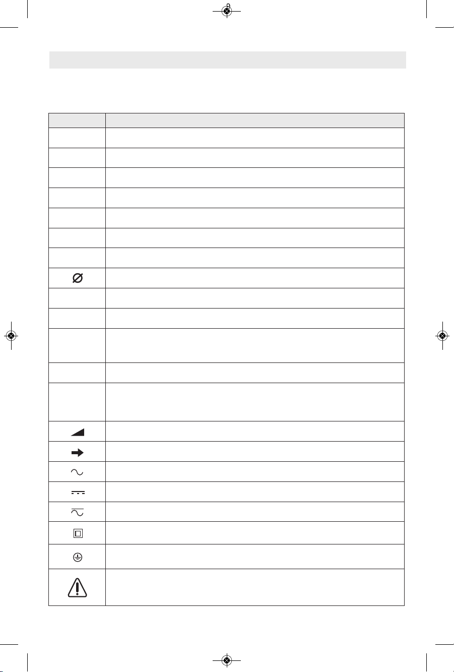
Symbols
IMPORTANT: Some of the following symbols may be used on your tool. Please study them
and learn their meaning. Proper interpretation of these symbols will allow you to operate the
tool better and safer.
Symbol Designation / Explanation
V Volts (voltage)
A Amperes (current)
Hz Hertz (frequency, cycles per second)
W Watt (power)
kg Kilograms (weight)
min Minutes (time)
s Seconds (time)
Diameter (size of drill bits, grinding wheels, etc.)
n
0
No load speed (rotational speed at no load)
n Rated speed (maximum attainable speed)
.../min
Revolutions or reciprocation per minute (revolutions, strokes, surface speed,
orbits etc. per minute)
0 Off position (zero speed, zero torque...)
1, 2, 3, ...
I, II, III,
Selector settings (speed, torque or position settings. Higher number means
greater speed)
0
Infinitely variable selector with off (speed is increasing from 0 setting)
Arrow (action in the direction of arrow)
Alternating current (type or a characteristic of current)
Direct current (type or a characteristic of current)
Alternating or direct current (type or a characteristic of current)
Class II construction (designates double insulated construction tools)
Earthing terminal (grounding terminal)
Warning symbol (alerts user to warning messages)
2610041357 09-15 GWS10 GWS13.qxp_GWS series 9/18/15 12:56 PM Page 7
-8-
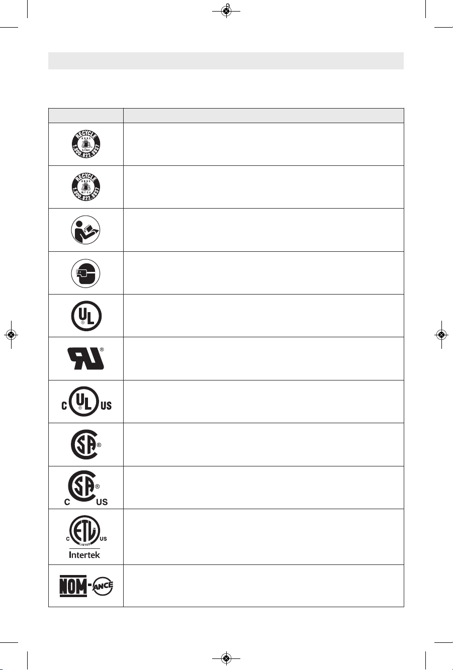
Symbols (continued)
IMPORTANT: Some of the following symbols may be used on your tool. Please study them
and learn their meaning. Proper interpretation of these symbols will allow you to operate the
tool better and safer.
Symbol Designation / Explanation
Designates Li-ion battery recycling program
Designates Ni-Cad battery recycling program
Alerts user to read manual
Alerts user to wear eye protection
This symbol designates that this tool is listed by Underwriters Laboratories.
This symbol designates that this component is recognized by Underwriters
Laboratories.
This symbol designates that this tool is listed by Underwriters Laboratories,
to United States and Canadian Standards.
This symbol designates that this tool is listed by the Canadian Standards
Association.
This symbol designates that this tool is listed by the Canadian Standards
Association, to United States and Canadian Standards.
This symbol designates that this tool is listed by the Intertek Testing
Services, to United States and Canadian Standards.
This symbol designates that this tool complies to NOM Mexican Standards.
2610041357 09-15 GWS10 GWS13.qxp_GWS series 9/18/15 12:56 PM Page 8
-9-
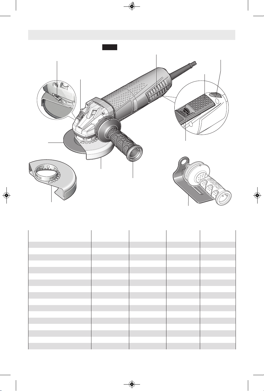
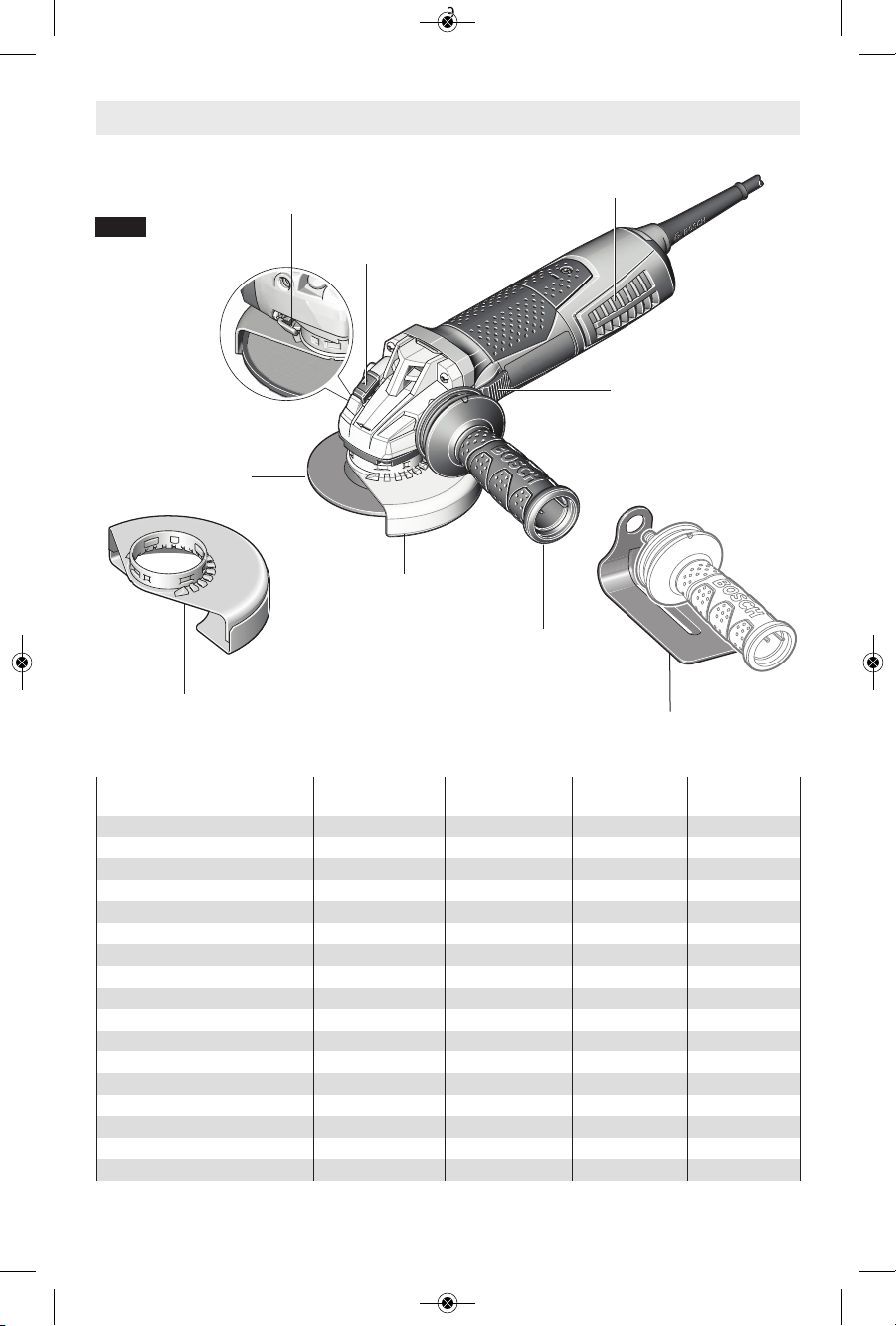
GUARD
RELEASE / ADJUSTMENT
BUTTON
SPINDLE LOCK
GRINDING
WHEEL
PADDLE
SWITCH
"LOCK-OFF" SWITCH
RELEASE LEVER
VIBRATION
CONTROL
SIDE HANDLE
TYPE 41/1A
CUTTING GUARD
(Optional Accessory)
TYPE 27
GRINDING
GUARD
VENTILATION
OPENINGS
HAND SHIELD
(Optional Accessory)
FIG. 1
Angle Grinders with Paddle Switch
LOCK-ON
SWITCH
(select models)
Model Number
GWS10-45P &
GWS10-45PD
GWS13-50P &
GWS13-50PD
GWS13-50VSP GWS13-60PD
Amps 10 13 13 13
Volts AC 120 120 120 120
Rated Speed (RPM), /min 11500 11500 2800 - 11500 9300
Spindle Thread 5/8"-11 5/8"-11 5/8"-11 5/8"-11
Max. grinding wheel ⌀ 4-1/2" (115mm) 5" (125mm) 5" (125mm) 6" (150mm)
Grinding wheel thickness
1/4" (6 mm) 1/4" (6 mm) 1/4" (6 mm) 1/4" (6 mm)
Max. cutting wheel ⌀ 4-1/2" (115mm) 5" (125mm) 5" (125mm) 6" (150mm)
Max. sanding disc ⌀ 4-1/2" (115mm) 5" (125mm) 5" (125mm) 6" (150mm)
Max. flap disc ⌀ 4-1/2" (115mm) 5" (125mm) 5" (125mm) 6" (150mm)
Max. wire wheel ⌀ 4" (102mm) 4" (102mm) 4" (102mm) 4" (102mm)
Max. wire cup wheel ⌀ 3" (76mm) 3" (76mm) 3" (76mm) 3" (76mm)
Variable speed - - ● Electronic clutch - ● ● ●
Constant response circuitry - ● ● ●
Restart protection - ● ● ●
Overload protection - ● ● ●
Soft start - ● ● ●
2610041357 09-15 GWS10 GWS13.qxp_GWS series 9/18/15 12:56 PM Page 9
-10-
GUARD
RELEASE / ADJUSTMENT
BUTTON
SPINDLE
LOCK
GRINDING
WHEEL
VIBRATION
CONTROL
SIDE HANDLE
TYPE 41/1A
CUTTING GUARD
(Optional Accessory)
TYPE 27
GRINDING GUARD
VENTILATION
OPENINGS
HAND SHIELD
(Optional Accessory)
FIG. 2
Angle Grinders with Slide Switch
SLIDE SWITCH
Model Number GWS10-45 GWS13-50 GWS13-50VS GWS13-60
Amps 10 13 13 13
Volts AC 120 120 120 120
Rated Speed (RPM), /min 11500 11500 2800 - 11500 9300
Spindle Thread 5/8"-11 5/8"-11 5/8"-11 5/8"-11
Max. grinding wheel ⌀ 4-1/2" (115mm) 5" (125mm) 5" (125mm) 6" (150mm)
Grinding wheel thickness
1/4" (6 mm) 1/4" (6 mm) 1/4" (6 mm) 1/4" (6 mm)
Max. cutting wheel ⌀ 4-1/2" (115mm) 5" (125mm) 5" (125mm) 6" (150mm)
Max. sanding disc ⌀ 4-1/2" (115mm) 5" (125mm) 5" (125mm) 6" (150mm)
Max. flap disc ⌀ 4-1/2" (115mm) 5" (125mm) 5" (125mm) 6" (150mm)
Max. wire wheel ⌀ 4" (102mm) 4" (102mm) 4" (102mm) 4" (102mm)
Max. wire cup wheel ⌀ 3" (76mm) 3" (76mm) 3" (76mm) 3" (76mm)
Variable speed - - ● Electronic clutch - ● ● ●
Constant response circuitry - ● ● ●
Restart protection - ● ● ●
Overload protection - ● ● ●
Soft start - ● ● ●
2610041357 09-15 GWS10 GWS13.qxp_GWS series 9/18/15 12:56 PM Page 10
-11-
Accessory speed rating must be equal to or greater than the tool’s speed rating. Do not exceed
the recommended wheel diameter.
Do not use Type 11 abrasive (cup) wheels with this tool. This tool is not
designed for use with type 11 (cup) abrasive grinding wheels.
!
WARNING
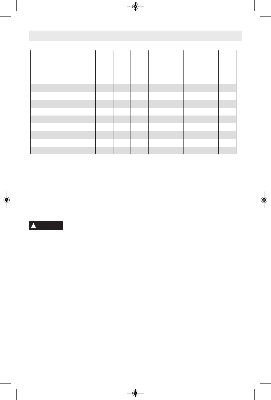
X = Tool is provided with attachments to perform this application.
O = Tool can use optional attachments to perform this application.
N = Tool is not capable of this application.
Application
Model Number
GWS10-45
GWS13-50
GWS13-50VS
GWS13-60
GWS10-45P
GWS10-45PD
GWS13-50P
GWS13-50PD
GWS13-50VSP
GWS13-60PD
Metal Grinding (Type 27) X X X X X X X X
Metal Grinding (Type 11) N
N N N N N N N
Metal Grinding (Type 1) N N N N N N N N
Metal Cutting (Type 41/1A) O
O O O O O O O
Concrete Surfacing O O O O O O O O
Concrete/Masonry Cutting O
O O O O O O O
Sanding O O O O O O O O
Wire Brushing (Wheel) X
X X X X X X X
Wire Brushing (Cup) O O O O O O O O
2610041357 09-15 GWS10 GWS13.qxp_GWS series 9/18/15 12:56 PM Page 11
Lock Nut & Backing Flange
Your tool is equipped with a threaded spindle
for mounting non-threaded hub accessories.
Always use the supplied backing flange with
a lock nut. Inner flange is keyed to output
sh aft (Fig. 3 ). A lways ens ure tha t ar bor
diam e t e r matches a c c e s s o r y diameter.
Accessories that run eccentrically may burst.
Installing Side Handle
Th e sid e han d l e is us e d to c o n t r o l and
balance the tool. Securely thread handle into
either side of gear housing, depending on
pe rson a l pr efer ence, com fort , ope rati on
being performed. The handle should always
be installed onto the guard protected side of
the tool (Fig. 4). Use the side handle for safe
control and ease of operation.
Hand Shield
The hand shield is to be used with backing
pads, sand ing discs and wire brus hes to
ke e p finge r s and h a n d away fro m work
su rfac e, s harp edg es, b urrs and deb ris.
Wh en us ing t he h a nd sh ield acc essor y,
insert side handle through hole in shield and
then thread into housing (Fig. 4). Ensure that
hand shield is positioned between hand and
backing pad, sanding disc or wire brush.
-12-
Functional Descriptions
Electronic Clutch:
The electronics in the powe r tool detects
situations where the wheel or accessory may
be at risk to bind. The electronics prevents
further rotation of the drive spindle by switching
th e power too l of f (it does no t prevent
kickback). To resume operation, turn on/off
switch to the off position, then restart tool.
Constant Response Circuitry:
Helps maintain near constant RPMs between
no-load and load conditions.
Soft Start:
Helps reduce stress on the motor that occurs
from a high torque start. Helps bring accessory
smoothly up to speed.
Automatic Restart Protection:
Helps prevent accidental startups after power
ha s bee n inte r rupte d , e.g. the too l was
unplugged with the switch locked in the on
position. To resume operation, turn on/off
switch to the off position, then restart the tool.
See the chart under Fig. 1 and Fig. 2 to find
out which grinders are equipped with the
Automatic Restart Protection.
Overload Protection:
Helps protect tool from excessive heat that
may damage motor. If tool stops or slows
during operation, allow motor to cool for 30
seconds by running no-load. If the overload
protection stops the tool repeatedly, excessive
force is causing the tool to overload. Stop
excessive force and readjust work piece to
reduce force applied.
Variable Speed:
Allows the grinders RPM to be adjusted for
greater versatility to match needs of specific
applications.
Assembly Instructions
FIG. 4
BACKING
FLANGE
LOCK NUT
FIG. 3
SPINDLE
(GUARD NOT SHOWN FOR CLARITY)
KEYED
TO SHAFT
HAND SHIELD
(Optional Accessory)
SIDE
HANDLE
2610041357 09-15 GWS10 GWS13.qxp_GWS series 9/18/15 12:56 PM Page 12
-13-
Installing Wheel Guards
(
Type 27 and Type 41/1A Wheel Guards)
A Type 27 guard must be
used with all grinding
w
heels, bonded body sanding flap discs,
wire brushes and wheels. The tool may be
used without a guard only when sanding with
conventional sanding discs.
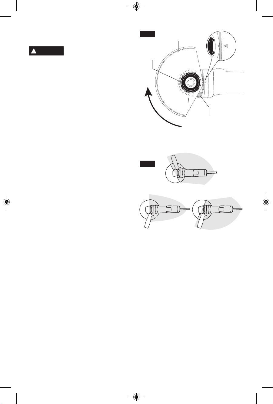
To attach guard (Fig. 5):
1. Unplug tool from power source.
2. Position appropriate guard on spindle neck
so arrows on guard and spindle neck align.
3. Rotate wheel guard clockwise 90º until
guard clicks in place.
4. Adjust guard by depressing guard release
bu t ton and r otate to desir e d po s ition .
Al ways po siti o n w heel gu ard betw een
operator and work piece and direct sparks
away from operator, Fig. 6.
5. Allow guard release button to click in place.
To remove wheel guard:
1. Depress guard release button and rotate
guard until arrows on guard and spindle
neck align.
2. Remove guard from spindle neck.
WHEEL
GUARD
SPINDLE
NECK
FIG. 5
O
PER
ATIN
G
ZO
N
E
!
WARNING
FIG. 6
GUARD
RELEASE
BUTTON
2610041357 09-15 GWS10 GWS13.qxp_GWS series 9/18/15 12:56 PM Page 13
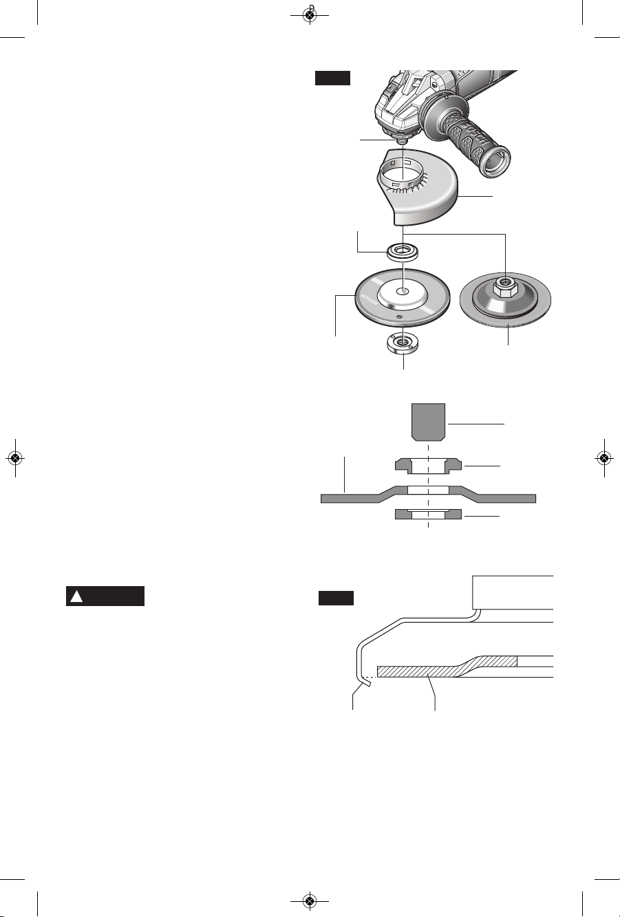
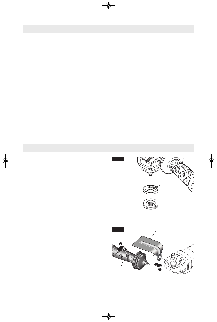
Abrasive Type 27 Grinding Wheel &
Sanding Flap Disk Assembly
Your tool is equipped with a threaded spindle
for mounting non-threaded hub accessories.
Always use the supplied backing flange with
a lock nut. Always ensure that arbor diameter
matches accessory diameter.
To install grinding wheel or flap disk
(Fig. 7):
1. Unplug tool from power source.
2. Install and adjust type 27 grinding guard to
the proper position for grinding as shown in
figure 5.
3. Place the backing flange on the spindle.
Turn flange until it locks with the base of the
spindle.
4. Place the grinding wheel onto the spindle
and align the arbor hole of the grinding
wheel with the shoulder of the backing
flange.
5. Thread the lock nut onto the spindle with the
lock nut relief facing the accessory.
6. Ti ghten lock nut with suppli ed lock nut
wrench while holding spindle lock.
TO REMOVE: Reverse procedure.
When using spin-on wheels:
Follow steps 1 & 2, then thread wheel
directly onto spindle withou t usin g the
supplied flanges.
TO REMOVE: Reverse procedure.
All parts of a spin-on wheel must be within lip
of grinding guard (Fig. 8). If spin-on wheel is
past lip of guard, do not use that wheel as it
does not fit on this grinder.
Do not use accessories
that run eccentrically. The
tool will vibrate excessively and may cause
loss of control and the accessory may burst.
!
WARNING
LOCK NUT
TYPE 27
GRINDING
WHEEL
BACKING
FLANGE
SPINDLE
-14-
SPINDLE
TYPE 27
WHEEL GUARD
FIG. 7
BACKING
FLANGE
TYPE 27 SPIN-ON
GRINDING WHEEL
TYPE 27
GRINDING
WHEEL
LOCK NUT
FIG. 8
SPIN-ON
WHEEL
LIP OF
GUARD
2610041357 09-15 GWS10 GWS13.qxp_GWS series 9/18/15 12:56 PM Page 14
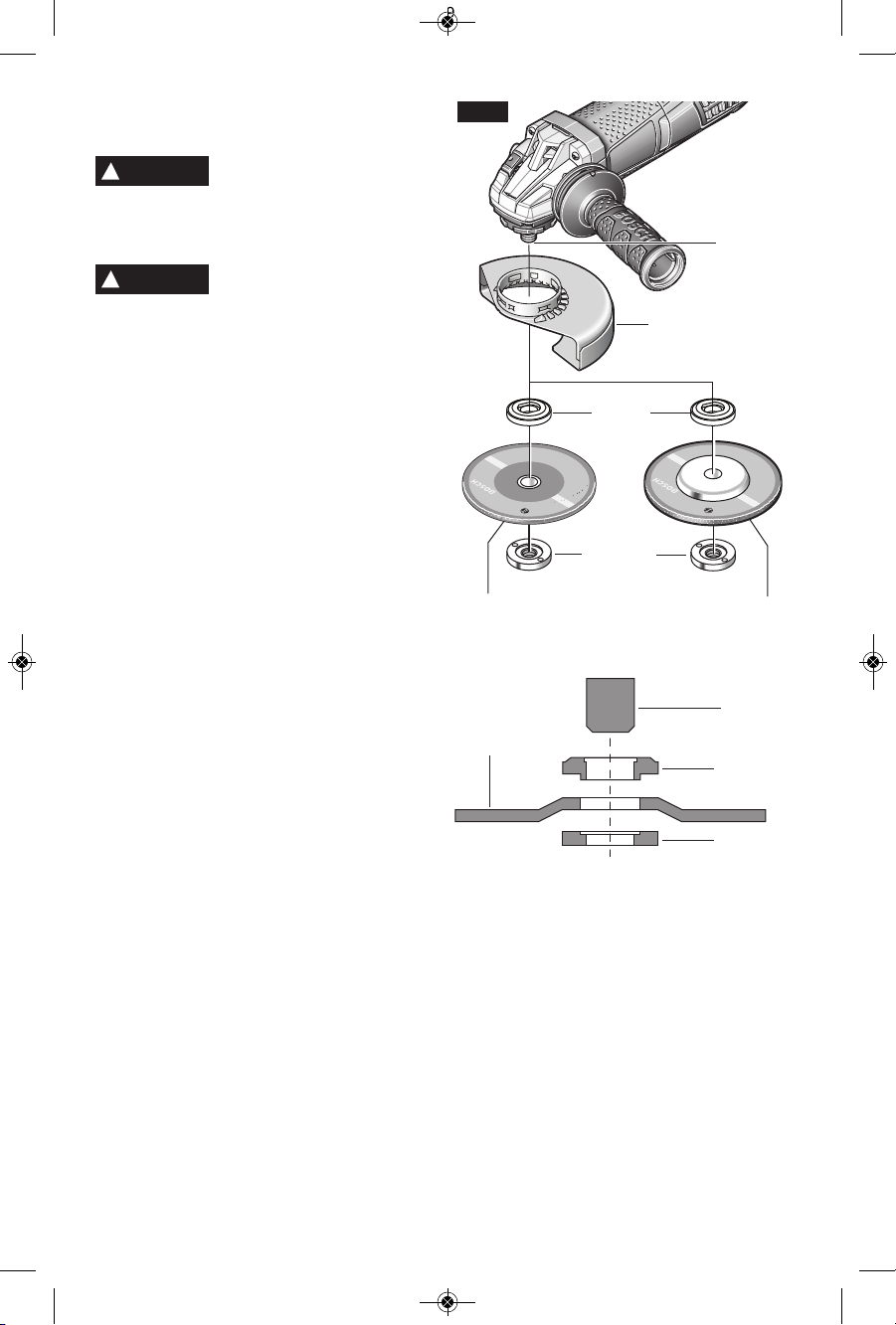
Abrasive Type 41/1A and 27 Cutting
Wheel Assembly
Always use Type 41/1A
cutting guard for cutting
o
perations. Other guards or attachments may
not protect operator in the event of a wheel
burst.
A type 27 wheel guard may
not be use d for all tool
operations. Do not discard guard when not
in use. Always reinstall wheel guard when
converting back to grinding operations.
To install cutting wheel (Fig. 9):
1.Unplug tool from power source.
2.Install and adjust Type 41/1A cutting guard
to the proper position for cutting as shown
in figure 5.
3.Place the backing flange on the spindle.
Turn flange until it locks with the base of the
spindle.
4.Place the cutting wheel onto the spindle
and alig n t he arbor h ole of the cutti ng
wheel with the shoulder of t he backing
flange.
5.Thread the lock nut onto the spindle with
the lock nut relief facing the accessory.
6.Ti ghten lock nut with supp lied lock nut
wrench while holding spindle lock.
TO REMOVE: Reverse procedure.
-15-
TYPE 41/1A
WHEEL GUARD
SPINDLE
BACKING
FLANGE
TYPE 41/1A
CUTTING
WHEEL
FIG. 9
LOCK NUT
TYPE 27A
CUTTING
WHEEL
LOCK NUT
TYPE 27A
CUTTING
WHEEL
BACKING
FLANGE
SPINDLE
!
WARNING
!
WARNING
2610041357 09-15 GWS10 GWS13.qxp_GWS series 9/18/15 12:56 PM Page 15
-16-
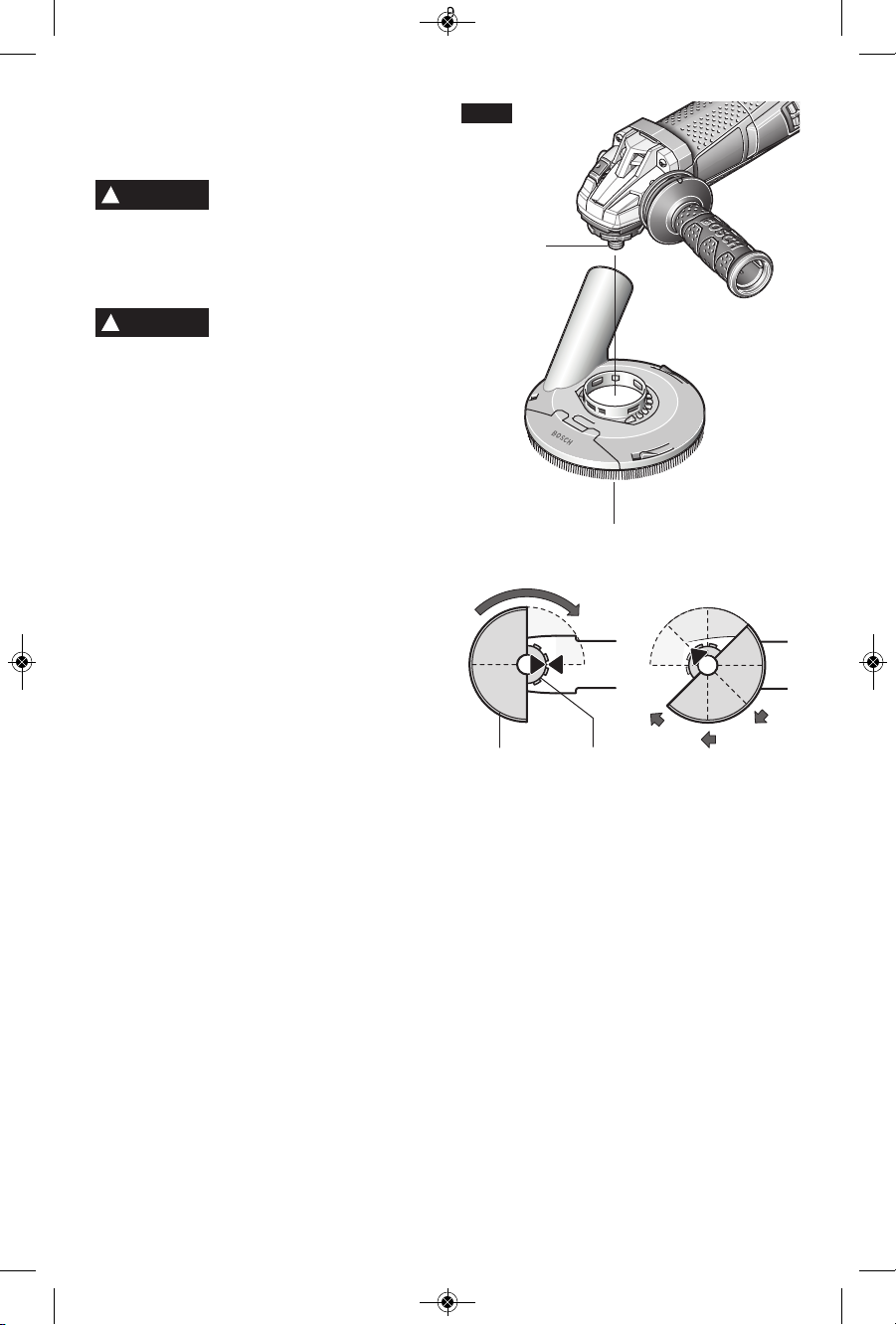
Concrete Dust Extraction
Attachment for Surfacing Grinding
Assembly
A type 27 grinding wheel
guard may not be used for
all tool operations. Do not discard guard
when not in use. Always reinstall whee l
gu ard when c onver ting bac k to gri ndin g
operations.
Dust Extrac t i o n
Attachment is not a guard,
do not use with bonded abrasive wheels.
Dust extraction attachment may not protect
operator in the event of a wheel burst.
To instal l concre te dust extrac tion
attachment (Fig. 10):
1.Unplug tool from power source.
2.Position appropriate attachment on spindle
neck with dust port pointing away from tool
body.
3.Rot a te a ttach ment clockwi se 9 0 º un til
guard clicks in place.
4.Adjust attachment by depressing guard
release button and rota t e to desired
position.
5.Allo w guar d rel e a se b u t ton t o cli c k in
place.
6.Place the backing flange on the spindle.
7.Pl ace the diamond cup wheel onto the
spindle and align with the flange.
8.Thread the lock nut onto the spindle with
the lock nut relief facing the accessory.
9.Ti ghten lock nut with supp lied lock nut
wrench while holding spindle lock.
When using spin on wheels, follow steps 1 5, then thread wheel directly onto spindle
without using the supplied flanges.
TO REMOVE: Reverse procedure.
SPINDLE
CONCRETE DUST EXTRACTION
ATTACHMENT
WHEEL
GUARD
SPINDLE
NECK
FIG. 10
!
WARNING
!
WARNING
2610041357 09-15 GWS10 GWS13.qxp_GWS series 9/18/15 12:56 PM Page 16
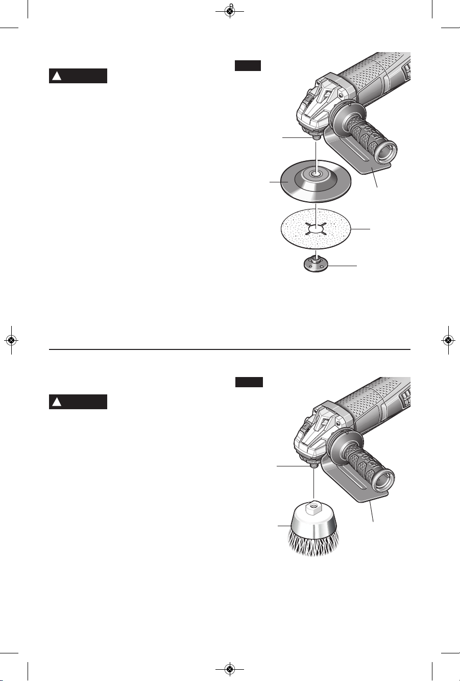
Wire Cup Brush Assembly
A type 27 wheel guard may
not b e us e d for all tool
operations. Do not discard guard when
not in use. Always reinstall wheel guard
when converting back to grinding operations.
The hand shield is to be used with backing
pads, sanding discs and wire brushes to keep
fingers and hand away from work surface,
sharp edges, burs and debris. When using the
hand shield accessory, insert side handle
through hole in shield and then thread into
housing (Fig 4). Ensure that hand shield is
positioned between hand and backing pad,
sanding disc or wire brush.
Do not use a knotted wire cup brush with
this tool. This tool does not have a guard for
knotted wire cup brushes.
To install wire cup brush (Fig. 12):
1. Unplug tool from power source.
2. Attach hand shield.
3. Thread wire cup brush onto spindle until
secure. Be sure to seat cup brush against
shoulder before turning tool “ON”.
TO REMOVE: Reverse procedure.
Sanding Assembly
A type 27 wheel guard may
not be use d for all tool
operations. Do not discard guard when not
in use. Always reinstall wheel guard when
converting back to grinding operations.
The hand shield is to be used with backing
pads, sanding discs and wire brushes to keep
fingers and hand away from work surface,
sharp edges, burs and debris. When using the
hand shield accessory, insert side handle
through hole in shield and then thread into
housing (Fig 4). Ensure that hand shield is
positioned between hand and backing pad,
sanding disc or wire brush.
To install backing pad and sanding disc
(Fig. 11):
1. Unplug tool from power source.
2. Attach hand shield.
3. Place the rubber back ing pad onto the
spindle shaft.
4. Cen t er the sandi ng d isc on top of t he
backing pad.
5. Insert the lock nut through the disc and
thread onto spindle.
6. Tighten l ock nut with supplied lock nut
wrench while holding spindle lock.
TO REMOVE: Reverse procedure.
SANDING
DISC
BACKING
PAD
LOCK NUT
SPINDLE
FIG. 11
SPINDLE
FIG. 12
WIRE CUP
BRUSH
-17-
!
WARNING
!
WARNING
HAND
SHIELD
HAND
SHIELD
2610041357 09-15 GWS10 GWS13.qxp_GWS series 9/18/15 12:56 PM Page 17
Masonry Cutting Guard
Assembly
A type 27 grinding wheel
guard may not be used for
all tool operations. Do not discard guard
when not in use. Always reinstall whee l
g
ua rd w hen convert ing back t o gr indin g
operations.
To improve ergonomics of your grinder when
cutting masonry, gearbox must be rotated
relative to the position of the switch as the
tool was assembled at the factory.
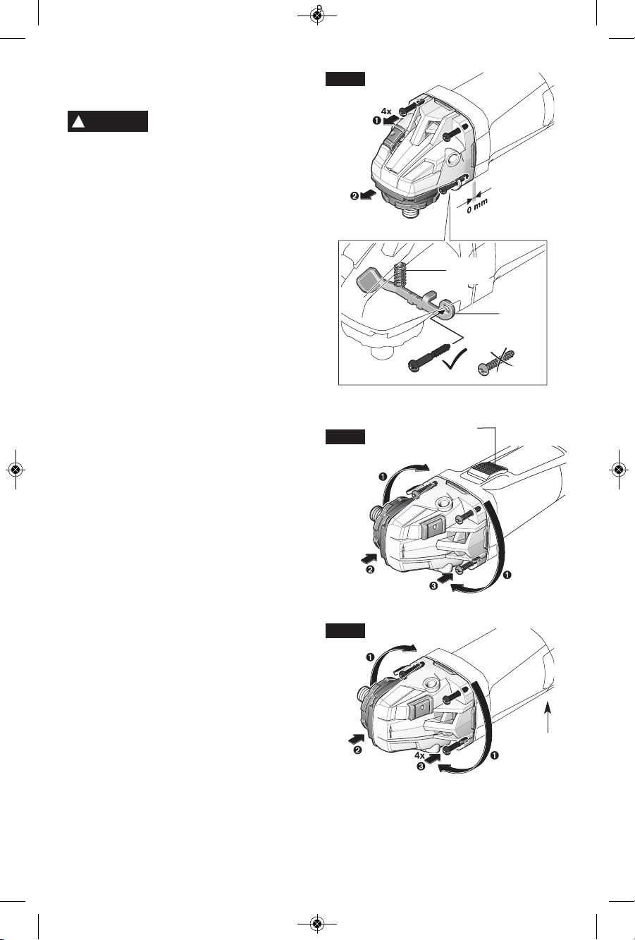
Rotate gearbox (Fig. 13):
1. Unplug tool from power source.
2. Comple t e l y unscrew the fou r screws
between the gear housing and motor body.
3. Rotate g e a r housing t o t h e proper
orientation without removing motor from
the housing.
a. For the slide switch models, rotate gear
housing 180 degrees in the direction
indicated in Fig 14a, so the switch is 90
degrees from the spindle.
b. For the paddle switch models, rotate
gear housing 90 degrees in the direction
indicated in Fig 14b, so the switch is
facing the work piece.
4. Screw in and tighten the four screws you
removed.
5. The screw holding the quick release lever
is longer than the other screws, this long
screw must stay with the quick release
lever when re-attaching gear housing for
the qu i ck re l e a se bu t t o n t o o p e r a t e
properly.
6. Attach proper dust collection guard with
foot and accessory.
Installing Masonry Type 1 Cutting Guard:
1. Use tool adjusted as show in figures 13
and 14a or 14b.
2. Unplug tool from power source.
3. Unscrew and remove side handle.
4. Sl ide dust extraction gu ard on sp ind le
neck.
5. Rotate attachment until stability bracket
and hole for side handled are aligned.
4x
-18-
FIG. 13
SLIDE
SWITCH
PADDLE
SWITCH
UNDER
TOOL
FIG. 14b
!
WARNING
180
DEGREES
180
DEGREES
90
DEGREES
90
DEGREES
FIG. 14a
SPRING
GUARD
RELEASE
LEVER
(x3)
2610041357 09-15 GWS10 GWS13.qxp_GWS series 9/18/15 12:56 PM Page 18
-19-
6. Screw in side handle to secure stability
brack et b etween the tool housin g and
handle.
7. Adjust guard to desired depth of cut.
TO REMOVE: Reverse procedure.
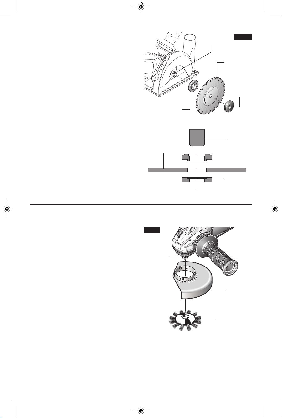
Installing dry diamond wheel (Fig. 15):
1. Place the backing flange on the spindle.
Turn flange until it locks with the base of the
spindle.
2. Pl ace th e d ry diamo nd wheel onto the
spindle and align the arbor hole of the
grinding wheel with the shoulder of the
backing flange.
3. Tighten lock nut with supplied lock nut
wrench while holding spindle lock.
TO REMOVE: Reverse procedure.
FIG. 15
SPINDLE
LOCK
NUT
BACKING
FLANGE
DRY
DIAMOND
WHEEL
LOCK NUT
BACKING
FLANGE
SPINDLE
DRY
DIAMOND
WHEEL
Wire Wheel Assembly
To install wire wheel (Fig. 16):
1. Unplug tool from power source.
2. Install and adjust type 27 grinding guard to
the proper position as shown in figure 5.
3. Thread wire w h e e l onto s p i n d l e until
secure.
NOTE: Be sure to seat wire wheel against
shoulder before turning tool “ON”.
TO REMOVE: Reverse procedure.
SPINDLE
TYPE 27
WHEEL GUARD
WIRE WHEEL
FIG. 16
2610041357 09-15 GWS10 GWS13.qxp_GWS series 9/18/15 12:56 PM Page 19
If the “Lock-ON” button is
continuously b e i ng
depressed, the trigger cannot be released.
N
ever leave the trigger
locked "ON" . Before
plugging the tool in, check that the trigger
lock is "OFF". Accidental start-ups could
cause injury.
Be aware of the location
and setting of the switch
"Lock-ON" button. If the switch is locked
"ON" during the use, be ready for emergency
situations to switch it "OFF".
Do not use t h e switch
"Lock-ON" feature in
situations where kickback is likely, such
as when working into a corner. When the
wheel binds, the to o l wi l l ki c k - b ack in
opposite direction of wheel rotation and the
rele ase of the trigger "L ock -ON" may be
difficult.
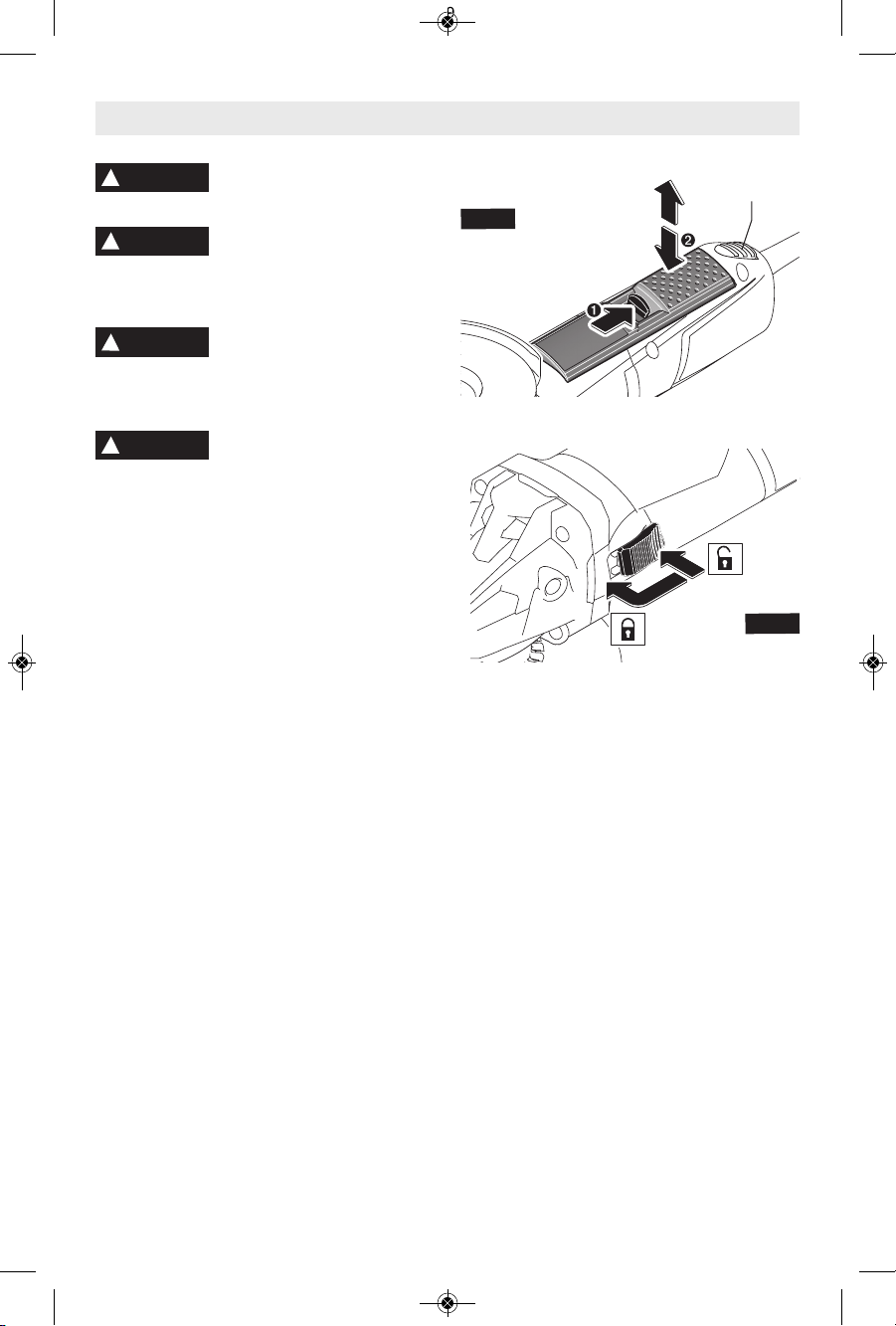
Paddle Switch (Fig. 17)
The paddle switch has a lock-off feature to
help prevent accidental startups. TO TURN
TOOL “ON”, push lock-off switch backward to
un lock the pad dle switch, the n sq ueez e
pa d d l e swi t c h . TO TU R N TOOL “OFF”,
re leas e pr essu re on pa ddle switch . Th e
switch is spring loaded and will return to the
“OFF” position automatically.
If your to o l ha s the LOCK - O N fe a t u r e
in c o r p o r a t e d into t h e paddle s w i t c h for
extended operation, there will be a red button
on the bottom of the tool directly behind the
paddle switch. TO LOCK SWITCH “ON” after
pa ddle swi tch has be en activa ted, pus h
“LOCK-ON” but ton while simult aneo usly
releasing pressure from the paddle switch.
TO TURN TOOL “OFF”, sq u e e z e a n d
release paddle switch.
Slide Switch (Fig. 18)
TO TURN TOOL ON, press the back of the
switch and slide forward towards the gear
housing an d in t o the ON po s i t i o n . TO
“LOCK-ON”, when the switch is slid into the
“ON” position, roll the switch forward. TO
TURN TOOL “OFF”, press the rear portion of
the switch. The switch is spring loaded and
will return to th e “ O F F ” p o s i t i o n
automatically.
!
WARNING
Operating Instructions
FIG
.
17
FIG.
18
-20-
!
WARNING
!
WARNING
!
WARNING
LOCK-ON
SWITCH
2610041357 09-15 GWS10 GWS13.qxp_GWS series 9/18/15 12:56 PM Page 20
Metal Cutting
A Type 1 wheel guard may
not be included with this
tool but is required when using a cutting
wheel. Cutting with a type 27 wheel guard
ma y not provi d e the opera t or suff i cient
protection in the event of a wheel burst.
With this grinder it i s possible to perfo rm
cutting of limited small stock such as metal
tubes, piping or rebar. When cutting, work with
moderate feed, adapted to the material being
cut. When cutting profiles and square bar, it is
best to start at the smallest cross section.
Always follow precautions for kickback.
1. Allow the tool to reach full speed before
touching the tool to the work surface.
2. The tool should always be used in such way
that the sparks are directed away from user.
3. App l y minim u m press u re to the wo r k
surface, allowing the tool to operate at high
speed. Cutting rate is greatest when the tool
operates at high speed.
4. Do not exert side pressure onto the cutting
disc. Do not tilt or oscillate the tool as wheel
may burst, (Fig. 20).
5. Remove the tool from the work surface
before turning the tool off. Allow the tool to
stop rotating before laying it down.
-21-
!
WARNING
FIG.
20
Metal Grinding
Grinding wheels should be carefully selected
in order to use the grinder most efficiently.
Wh e e l s vary i n type o f abr a s i v e , bond,
hardness, grit size and structure. The correct
wheel to use is determined by the job. Use
disc grindi ng w heel s for f ast grinding of
structural steel, heav y weld beads, steel
casting, sta inless steel and other ferrous
metals.
1. Allow the tool to reach full speed before
touching the tool to the work surface.
2. Apply mi n i m u m pressure t o the w o r k
surface, allowing the tool to operate at high
speed. Grinding rate is greatest when the
tool operates at high speed.
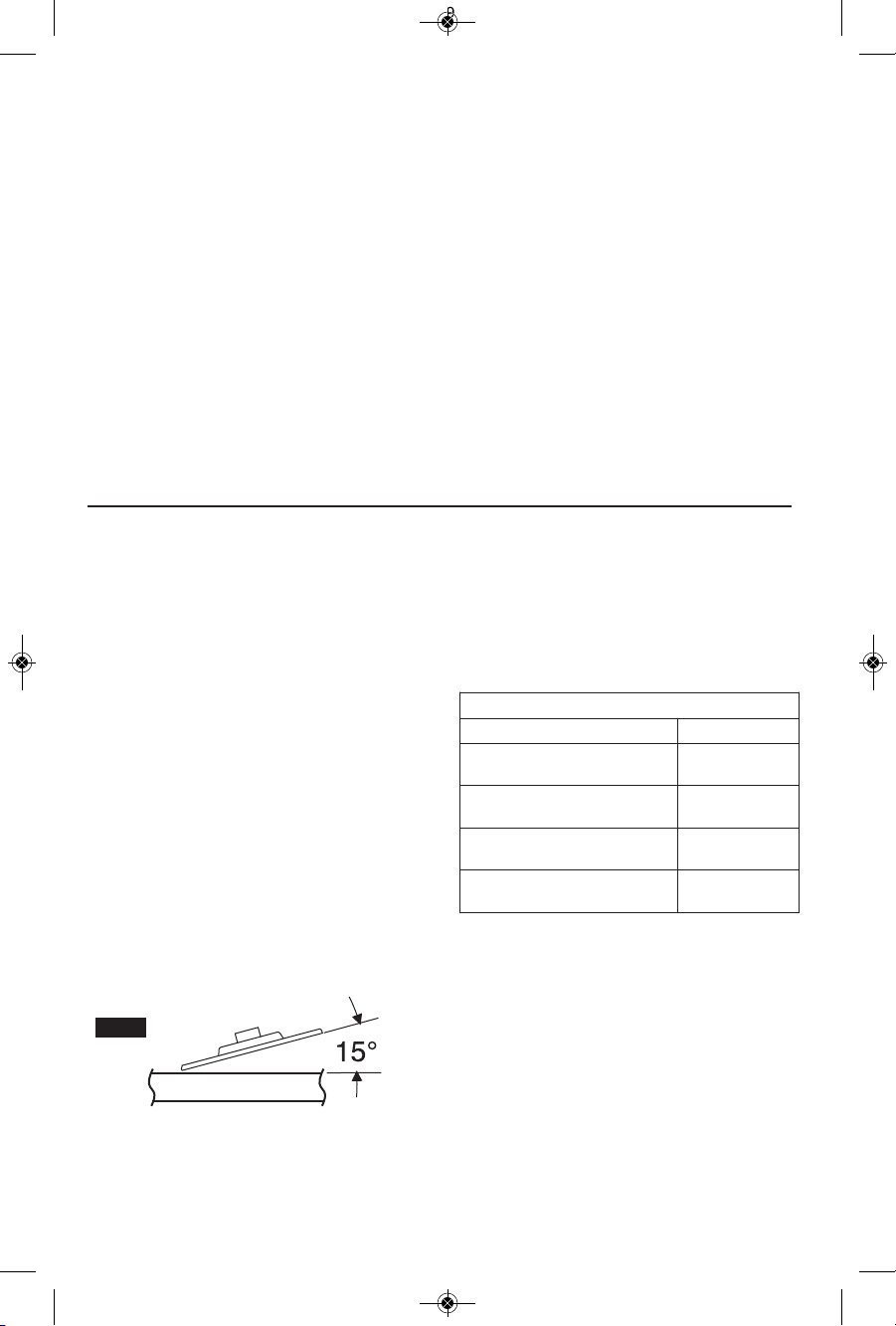
3. Maintain a 10° to 15° angle between the
tool and work surface, (Fig. 19).
4. Continuously move the tool at a moderate
speed to avoid creating gouges in the work
surface.
5. Remove the tool from work surface before
tu rnin g to o l of f. A llow the to ol to st o p
rotating before laying it down.
Tip: When grinding with a new wheel be
certain to grind while pulling tool backwards
un til the whe el b ecome s ro unde d on its
edge. New wheels have sharp edges which
tend to “bite” or cut into the work piece when
pushed forward.
FIG
.
19
2610041357 09-15 GWS10 GWS13.qxp_GWS series 9/18/15 12:56 PM Page 21
-22-
Masonry / Concrete Cutting
With this grinder it i s possible to perfo rm
cutting of concrete and masonry materials.
Wh en cutt ing, wo rk with mo derat e f eed,
adapted to the material being cut.
Always follow precautions for kickback.
Operate the tool with a dust extraction system
and personal dust protection, e.g. respirator,
dust mask, etc. The vacuum used for this
application must be approved for the extraction
of masonry and concrete dust. Bosch sells
suitable vacuum cleaners.
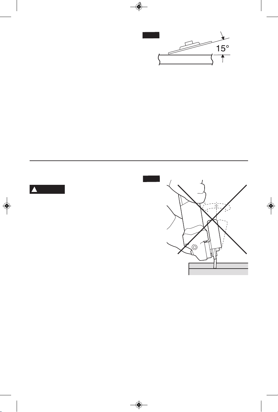
Never pull the tool backward
since blade will climb out of
the material and KICKBACK will occur.
1. Allow the tool to reach full speed before
touching the tool to the work surface.
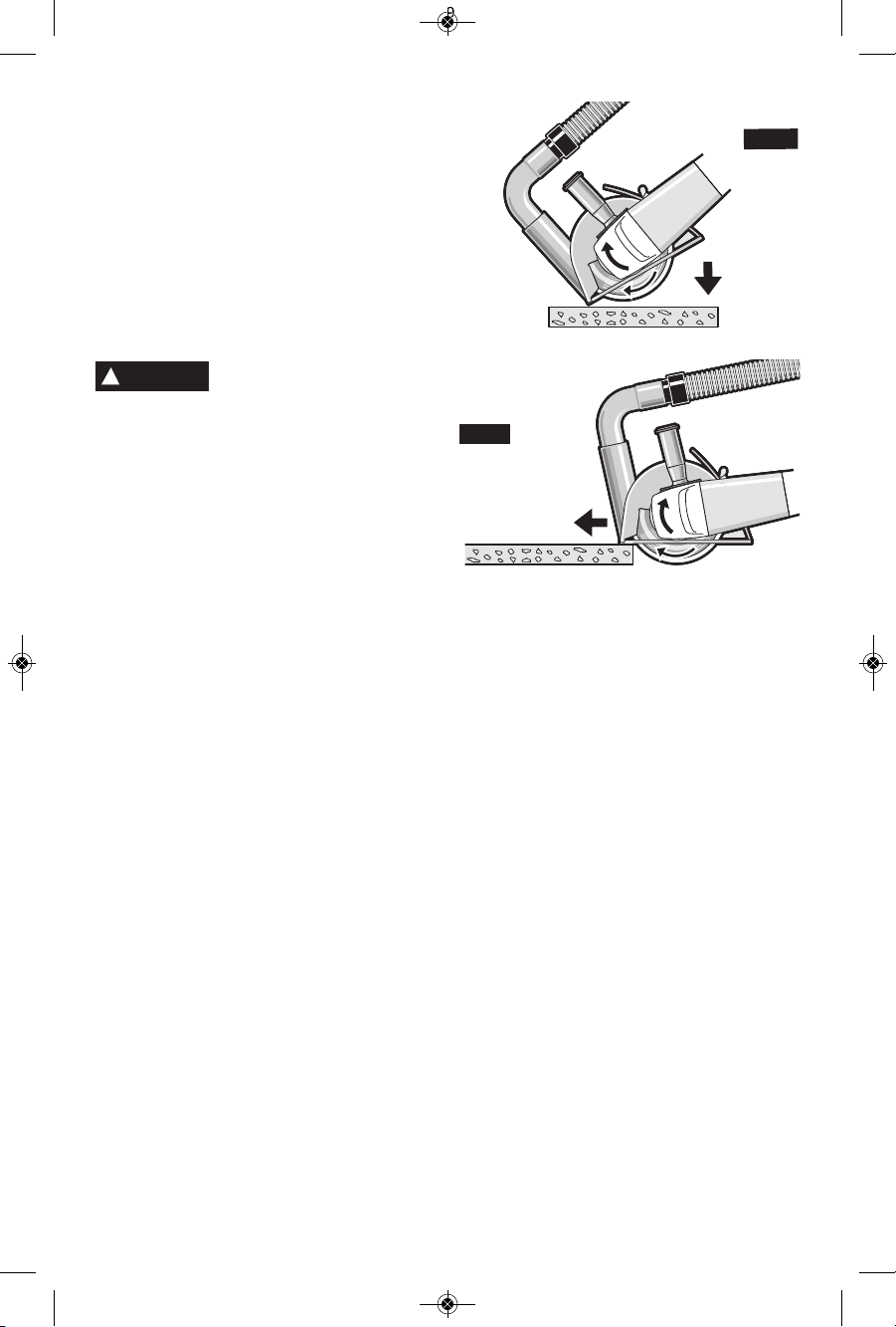
2. If plunge cutting:
a. Tilt tool forward with wheel lined up with
the cut line an d hold the tool by the
grinder body and the auxiliary handle
(Fig. 21).
b. Gradually lower the rear of tool using the
front end of the foot as the hinge point.
c. When the foot rests flat on the surface
being cut, proceed cutting in forward
direction to end of cut.
3. Always maintain contact between the guard
foot and work piece.
4. Slide the tool forward at a moderate speed
adapted to the material being cut. Always
cut towards the dust e xtr action p ort to
ma x imize dust ex tract i on and reduce
likelihood of kickback (Fig. 22).
5. App l y minim u m press u re to the wo r k
surface, allowing the tool to operate at high
speed. Cutting rate is greatest when the tool
operates at high speed.
6. When the cut is completed, remove tool
from work piece before turning off. Allow
wheel to stop rotating before setting tool
down.
Tip: When performing deep cuts, it is best to
cut in several shallow passes. Each pass
should be only to the segment depth of the
wheel. Masonry dust is abrasive and may
wear and weaken the segment bond.
When cutting especially hard material, e. g.,
concrete with high pebble content, the dry
diamond wheel can overheat and become
damaged. This is clearly indicated by circular
sparking of the rotating dry diamond wheel. In
this case, interrupt the cutting process and
allow the dry diamond wheel to cool by running
the tool for a s hort perio d o f t ime at th e
maximum speed with no-load.
Noticeable decreasing work progress and
circ ular sparking are indicati ons of a d ry
diamond wheel that has become dull. Briefly
cutting into abrasive materials (e. g. brick) can
resharpen the wheel.
FIG. 22
FIG
.
21
!
WARNING
2610041357 09-15 GWS10 GWS13.qxp_GWS series 9/18/15 12:56 PM Page 22
Sanding
Sanding discs range in grit from 16 (very
course) to 180 (very fine). They also vary in
size and spacing of grit.
OPEN COAT (type H) is used for soft materials
and on paint and varnish, CLOSED COAT
(type K) is used for metal, hardwood, stone,
marble and other materials. To obtain best
results, select sanding discs carefully. Many
jobs require the use of several grit sizes and at
times both open coat and closed coat discs are
required to complete the job. See chart for
application examples.
1. Allow the tool to reach full speed before
touching the tool to the work surface.
2. App l y minim u m pressu r e to the wo r k
surface, allowing the tool to operate at high
speed. Sanding rate is greatest when the
tool operates at high speed.
3. Maintain a 10° to 15° angle between the tool
and work surface, (Fig. 23).
4. Continuously move the tool at a moderate
speed to avoid creating gouges in the work
surface.
5. Remove the tool from work surface before
turning tool off. Allow the tool to stop rotating
before laying it down.
Tips: Guide the disc with crisscross strokes.
Do not use a circular motion as this makes
swirl marks.
-23-
Operation: Refinishing painted wood or metal surfaces.
REMARKS GRIT
To remove paint and to smooth
surface irregularities.
Coarse
16-24-30
To smooth the rough sanding.
Medium
36-50-80
To remove scratches left by
previous discs.
Fine
100-120
To smooth surfaces for painting,
polishing or waxing.
Very Fine
150-180
Concrete Surfacing
Operate the tool with a dust extraction system
and personal dust protection, e.g. respirator,
dust mask, etc. The vacuum used for this
application must be approved for the extraction
of masonry and concrete dust. Bosch sells
suitable vacuum cleaners.
Diam ond c up wh eels sho uld b e car efully
selected in order to use the grinder most
efficiently. Wheels vary in type of material they
are designed to remove and how aggressively
they will remove material. The correct wheel to
use is determined by the job.
1. Allow the tool to reach full speed before
touching the tool to the work surface.
2. Hold the tool with two hands and keep
diamond wheel flat on the work surface.
3. Apply minimum pressure, allowing the tool
t
o operate at high speed. Removal rate is
greatest when the tool operates at high
speed.
4. Continuously move the tool at a moderate
speed to avoid creating gouges in the work
surface.
5. Remove the tool from work surface before
turning tool off. Allow the tool to stop rotating
before laying it down.
Tip: For optimal dust collection, all sides of the
surfacing dust collection guard must stay in
contact with the surface and the surfacing
guard must be connected to a vacuum. A dull
diamond wheel can be sharpened by briefly
surf acing an a bra sive material (eg. sand
stone).
FIG. 23
2610041357 09-15 GWS10 GWS13.qxp_GWS series 9/18/15 12:56 PM Page 23
 Loading...