

Page 1

Applications manual
For tankless and point of use water heaters
Page 2

|
2
Table of Contents
1 Introduction 3
2 Bosch Water Heating Models 3
2.1 Sizing tankless water heaters 4
2.2 Bosch GWH 715 ES 6
2.3 Bosch GWH C 800 ES 7
2.4 Outdoor Installation for GWH 715 ES and GWH C 800 ES 8
2.5 Bosch GWH 345 ESR 9
2.6 Bosch GWH 450 ESR 10
2.7 Bosch GWH 425 EF 11
2.8 Bosch GWH 425 HN 12
2.9 Bosch GWH 425 PN 13
2.10 Bosch GWH 260 PN 14
2.11 Powerstream Pro RP17PT, RP27PT 15
2.12 Powerstream Pro RP1P, RP2P, RP3P, RP7P, RP9P, RP12PT 16
2.13 Ariston Pro GL2.5Ti, GL4Ti, GL8Ti 17
3 Domestic Water Heating Applications 18
Applications manual
3.1 Point-of-use applications 18
3.2 Whole house applications 22
4 High Volume Potable Water Heating 26
4.1 Parallel unit applications 26
4.2 Cascade unit applications 28
4.3 External storage tank loading applications 29
5 Open Loop Space Heating 32
5.1 External storage tank 32
5.2 Indirect tank applications 42
6 Maintenance Drawings 44
6.1 Descaling procedure 44
6.1 Descaling procedure diagram 45
Application manual | 11.2007
Bosch Water Heating
Page 3

Applications manual
1 Introduction
The Bosch Applications Manual is intended to present some of the
most common applications of the Bosch line of tankless and point of
use water heaters. Application drawings are shown with both piping
and corresponding electrical schematics where applicable. Auxiliary
equipment depicted does not necessarily represent any one manufacturer or specifi c model number. There are a wide variety of
techniques, practices and piping strategies possible when installing
water heating appliances. It is the responsibility of the installing
contractor to determine the most suitable arrangement for the
application.
Although this manual covers many common applications for our
products, system possibilities are virtually endless. Should you
encounter an application that is not covered in this manual or have
any questions regarding any of its content, we encourage you to
contact your local sales representative or us directly at Bosch Water
Heating.
This is not a substitute for any of the product’s installation manuals.
All specifi cations subject to change.
Installation must conform with local codes or, in the absence of
local codes, the National Fuel Gas Code ANSI Z 223.1/NFPA 54.
In Canada: Installation must conform with CGA B149.(1,2) INSTALLATION CODES and/or local installation codes.
| 3
2 Bosch Water Heating Models
This section describes the water heaters available from Bosch Water
Heating. The information given in each section provides a general
overview to the specifi cations of that particular model. More detai-
led information is contained in the installation manuals. Download
these manuals at www.BoschPro.com.
Applications manual | 11.2007Bosch Water Heating
Page 4

|
4
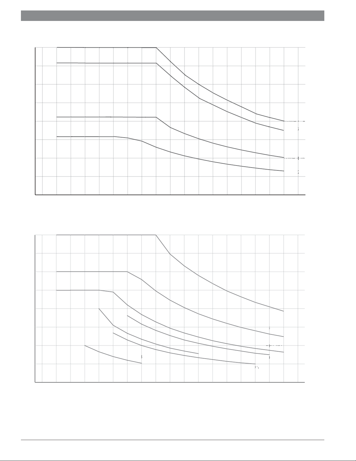
2.1 Sizing tankless water heaters
Defi nitions
Major applications (2 GPM or more): Washing machine, bath tub,
shower nozzle
Minor applications(1.5 GPM or less): Low fl ow shower head,
bathroom sink, kitchen sink
Rule of thumb sizing
The tables below provide a general rule of thumb when sizing for
most residential applications. For commercial applications or for a
more detailed sizing method, use the instructions below in conjunction with the charts on the next page.
Sizing by Chart
Measure the fl ow rates at each fi xture that will be used simultane-
ously and add them together. If only one application will be used
at a time measure each fi xture and use the maximum fl ow rate
observed.
Rule of Thumb Sizing
Model Number Number of Major
Applications
Number of Minor
Applications
Applications manual
GWH 715 ES 2 0
GWH C 800 ES 2 1
GWH 425 HN/PN/EF 1 1
GWH 425 HN/PN/EF 0 2
GWH 260 PN 1 0
RP17PT 1 0
RP27PT 1 1
Using a known volume container, record several fi ll times. Per-
form the calculation below to determine the fl ow rate (a one
gallon fi ll time of 30 seconds is 2.0 gallons per minute (GPM):
Flow rate (GPM) =
Volume (gallons)
Fill time (sec)
Using a thermometer, measure the incoming water temperature.
Subtract this temperature from the desired hot water temperature
to get the degree rise. So, if the desired hot water temperature is
120F and incoming temperature is 55F, the desired degree rise is
65F.
This example requires a fl ow rate of 2.0 GPM at a 65˚F rise. The
data point is shown on each graph. Since the demand is above
the GWH 260 PN capacity, this application would require a GWH
425 HN/PN/EF gas tankless water heater. The electrical model
used for this application would be the RP27PT electric tankless
water heater.
sec
x
60
min
Application manual | 11.2007
Bosch Water Heating
Page 5
Applications manual
GWH 425 PN/HN
GWH 260 PN/HN
t
C
0
5
0
5
0
5
0
5
0
e
M
P
Note
s
GPM
8
7
6
5
4
3
2
1
| 5
0
10 20 30 40 50 60 70 80 90
Degree rise (°F)
as Appliance Sizing Char
P
4.
.
.
.
.
1.
1.
P7
.
.
10 20 30 40 50 60 70 80 90
ectric Appliance Sizing Chart
: Maximum flow rates dependant on site condition
Degree ris
Applications manual | 11.2007Bosch Water Heating
Page 6
|
6
2.2 Bosch GWH 715 ES
Applications manual
Features:
Electronic ignition and built in power vent
82% thermal effi ciency
Vents vertically or horizontally with 3" or 4" stainless steel (AL29-
4C)
Direct vent room-sealed combustion
Computerized temperature control — ensures temperature stability
Model GWH 715 ES N for natural gas (NG) supply
Model GWH 715 ES L for liquid propane (LP) supply
15-year warranty
Qualifi es for $300 tax credit
GWH 715 ES Technical Specifi cations
Gas input Natural Gas: 19,900 - 199,000 BTU
LP Gas: 19,900 - 199,000 BTU
Minimum fl ow to activate 0.65 gallons per minute (gpm)
Flow rates 45˚F rise @ 7.2 gpm
55˚F rise @ 5.9 gpm
65˚F rise @ 5.0 gpm
77˚F rise @ 4.2 gpm
90˚F rise @ 3.6 gpm
Thermal Effi ciency NG: 82% LP: 82%
Dimensions 30½" h x 17⅞" w x 11¼" d
Weight 67 lbs.
Modulating gas valve yes
Ignition Electronic
Accessories Outdoor kit (PTOK)
Wireless Remote (TSTAT2)
Tankless Link Cascading Kit (TLINK)
Freeze Prevention Kit (8700400022)
Water Filter Kit (8703305356)
GWH 715 ES Installation Specifi cations
Gas connection ¾" Male NPT
Water connections ¾" Male NPT
NG gas pressure Minimum: 4" W.C.
Maximum: 14" W.C.
LP gas pressure Minimum: 9" W.C.
Maximum: 14" W.C.
Water pressure
(Static)
Minimum: 30 PSI
Minimum well pressure: 40 PSI
Maximum: 150 PSI
Electrical supply 120VAC - plugs in
Venting 3" or 4" stainless steel (AL29-4C)
direct vent
room-sealed combustion
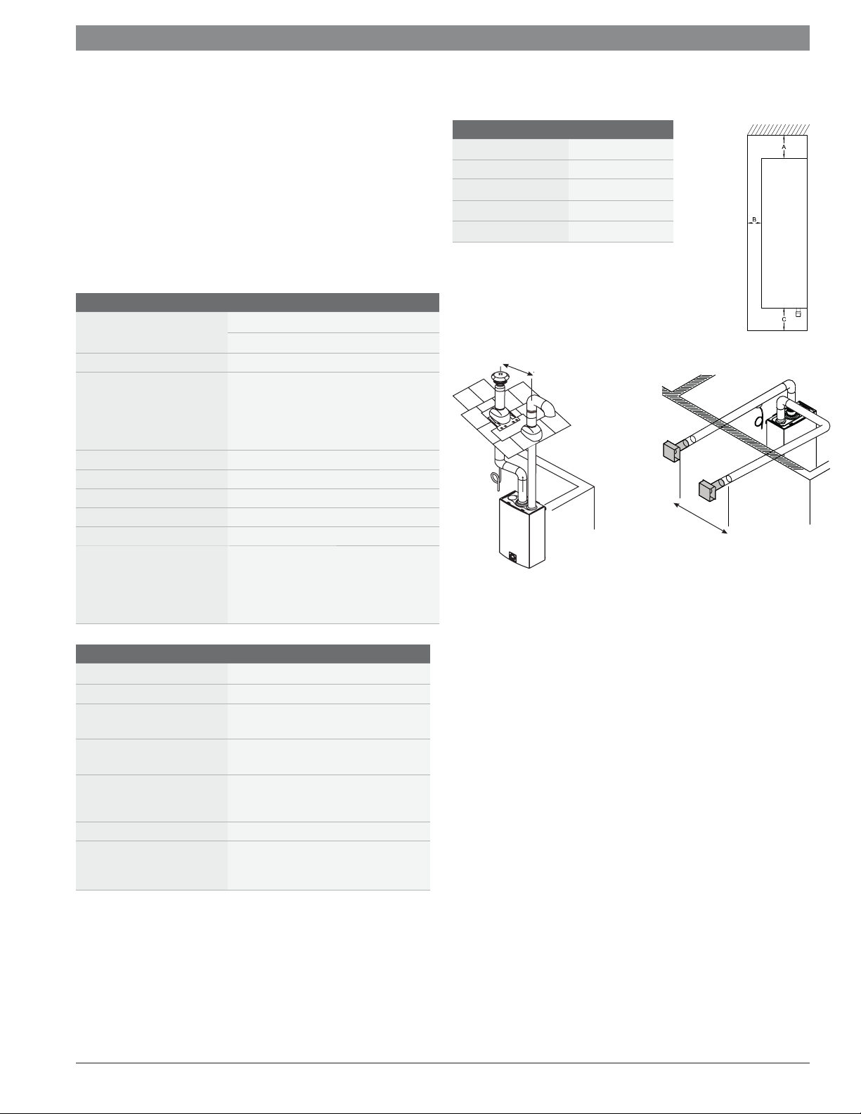
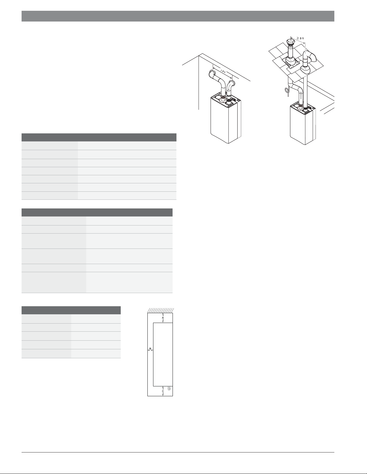
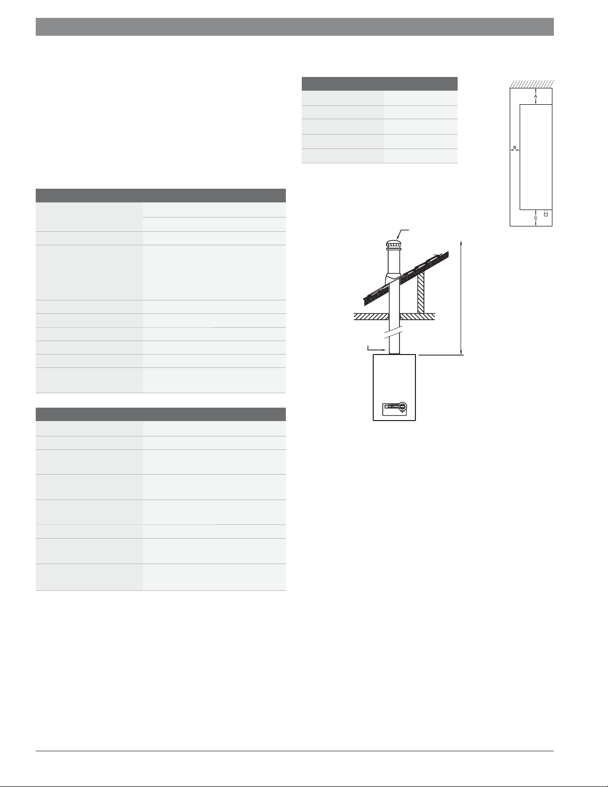
GWH 715 ES Installation Clearances
Top (A) 12"
Front (B) 1"
Back 0"
Sides 1"
Floor (C) 12"
3ft minimum
distance
3ft minimum
distance
Fig. 1 Venting confi gurations
Installation guidelines:
Venting:
Must be 3" or 4" AL29-4C sealed stainless steel vent pipe.
Slope horizontal runs up to termination ¼" per foot. The last
horizontal section of exhaust vent pipe between last elbow and
termination must slope down to the termination ¼" per foot.
Do not combination vent with any other appliance.
Install condensate drain where applicable.
See manual for vent terminator clearances.
Gas piping:
Heater will not function properly without adequate supply gas
pressure.
Any appliance connector should be ¾" minimum diameter
Plumbing:
Install the included pressure relief valve and pipe to suitable
drain.
Minimum piping diameter is ¾".
Do not solder directly to the bottom of the unit.
Use unions to facilitate easy future maintenance.
Use full port ball valves for isolation valves.
Partially fi ll condensate drain tube loop (where applicable) with
water prior to start up.
Application manual | 11.2007
Bosch Water Heating
Page 7
Applications manual
2.3 Bosch GWH C 800 ES
Features:
Electronic ignition and built in power vent
Condensing technology with 92% thermal effi ciency
Vents vertically or horizontally with 3" or 4" PVC, CPVC or ABS
(Schedule 40) vent pipe.
Direct vent room-sealed combustion with concentric venting
option
Computerized temperature control — ensures temperature stability
Model GWH C 800 ES N for natural gas (NG) supply
Model GWH C 800 ES L for liquid propane (LP) supply
15-year warranty
Qualifi es for $300 tax credit
GWH C 800 ES Technical Specifi cations
Gas input Natural Gas: 19,900 - 199,000 BTU
LP Gas: 19,900 - 199,000 BTU
Minimum fl ow to activate 0.65 gallons per minute (gpm)
Flow rates 45˚F rise @ 8.0 gpm
55˚F rise @ 6.4 gpm
65˚F rise @ 5.5 gpm
77˚F rise @ 4.6 gpm
90˚F rise @ 3.9 gpm
Thermal Effi ciency NG: 92% LP: 92%
Dimensions 30½" h x 17⅞" w x 11¼" d
Weight 74 lbs.
Modulating gas valve yes
Ignition Electronic
Accessories Outdoor kit (PTOK)
Wireless Remote (TSTAT2)
Tankless Link Cascading Kit (TLINK)
Freeze Prevention Kit (8700400022)
Water Filter Kit (8703305356)
Concentic Termination Kit
(BWH60L46)
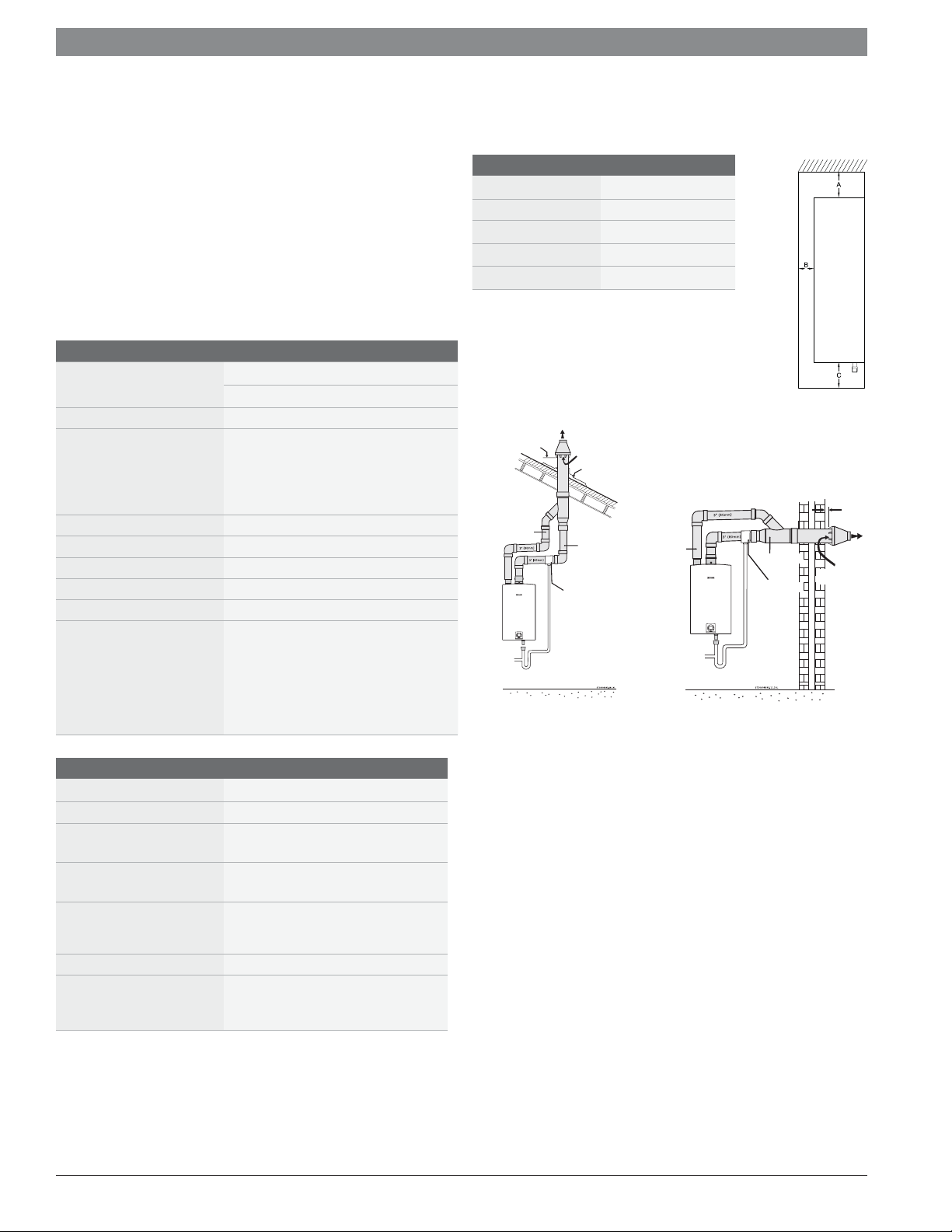
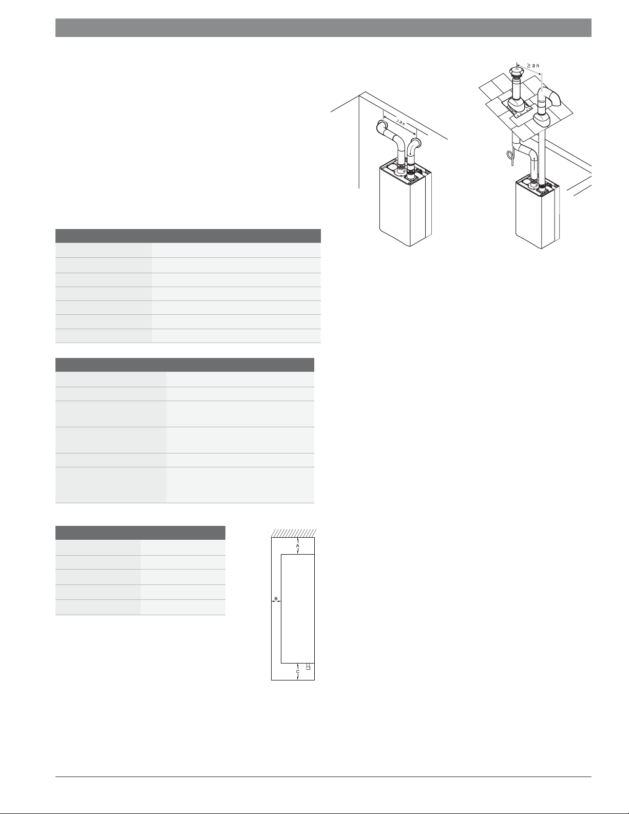
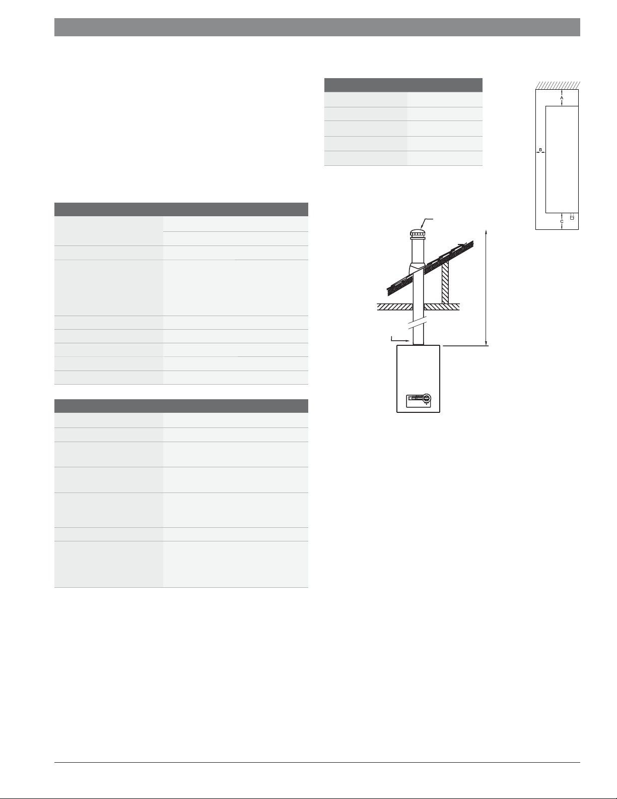
GWH C 800 ES Installation Clearances
Top (A) 12"
Front (B) 1"
Back 0"
Sides 1"
Floor (C) 12"
MAINTAIN 12 IN.
(1
8 IN. FOR CANADA)
MINIMUM CLEARANCE
ABOVE
HIGHEST ANTICIPATED
SNOW LEVEL.
MAXIMUM OF 24 IN.
ABOVE ROOF.
INTAKE
Fig. 1 Venting confi gurations
VENT
DRAIN TEE
COMBUSTION
AIR
ROOF BOOT/
FLASHING (FIELD
SUPPLIED
EXHAUST
INTAKE
EXHAUST
DRAIN TEE
| 7
MINIMUM
VENT
COMBUSTION
1”
AIR
GWH C 800 ES Installation Specifi cations
Gas connection ¾" Male NPT
Water connections ¾" Male NPT
NG gas pressure Minimum: 4" W.C.
Maximum: 14" W.C.
LP gas pressure Minimum: 9" W.C.
Maximum: 14" W.C.
Water pressure
(Static)
Minimum: 30 PSI
Minimum well pressure: 40 PSI
Maximum: 150 PSI
Electrical supply 120VAC - plugs in
Venting 3" or 4" PVC, CPVC, or ABS
(Schedule 40) direct vent sealed
combustion
Installation guidelines:
Venting:
Must be 3" or 4" PVC, CPVC or ABS (Schedule 40) vent pipe.
Attach drain for internal condensate siphon and dispose of
according to local codes.
Do not combination vent with any other appliance.
Install an external condensate drain where applicable.
See manual for vent terminator clearances.
Gas piping:
Heater will not function properly without adequate supply gas
pressure.
Any appliance connector should be ¾" minimum diameter
Plumbing:
Install the included pressure relief valve and pipe to suitable
drain.
Minimum piping diameter is ¾".
Do not solder directly to the bottom of the unit.
Use unions to facilitate easy future maintenance.
Use full port ball valves for isolation valves.
Partially fi ll condensate drain tube loop (where applicable)
Applications manual | 11.2007Bosch Water Heating
Page 8
8
|
Applications manual
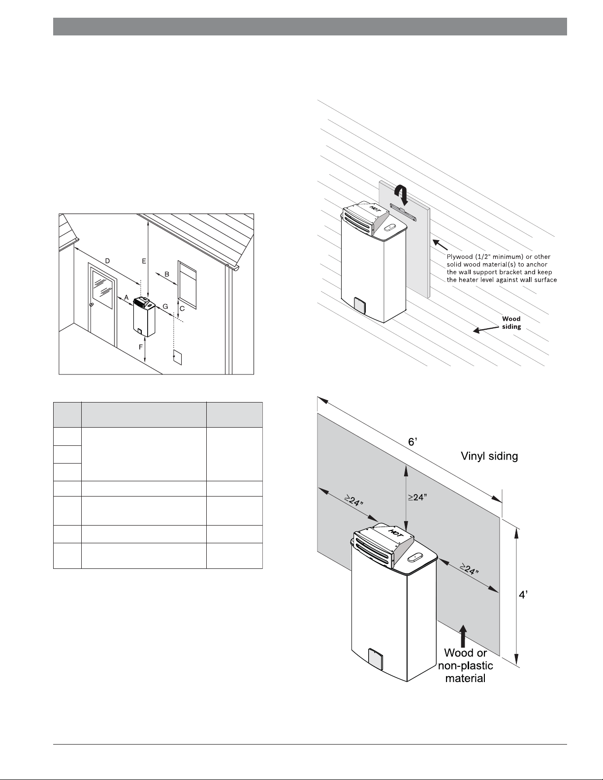
2.4 Outdoor Installation for GWH 715 ES,
and GWH C 800 ES
Outdoor Kit (PTOK) installation:
The installation of this outdoor kit (PTOK) is required when
installing either of the above appliances outdoors
Outdoor cap easily retrofi ts to these indoor models
Outdoor kit comes with Freeze Prevention which must be installed
Exterior water piping should be protected if freezing conditions
could exist
Minimum clearances:
Installation on wood siding
Ref. Description
A
Directly below or adjacent to
an opening; operable
B
windows, doors and any fresh
air openings
C
D From any adjacent wall ≥ 4 ft
Below a gutter, sanitary
E
pipework, eaves or overhang
F Above ground ≥ 1 ft
From a gas meter or gas
G
regulator
Outdoor Installation Clearances
Source: NFPA 54 National Fuel Gas Code
ANSI Z223.1
Installation on vinyl siding:
Min.
distances
≥ 4 ft
≥ 3 ft
≥ 5 ft
Application manual | 11.2007
Bosch Water Heating
Page 9
Applications manual
2.6 Bosch GWH 345 ESR
Features:
Specifi cally designed for recirculating applications
Electronic ignition and built in power vent
GWH 345 ESR thermal effi ciency of 82%
Vents vertically or horizontally with 3" stainless steel (AL29-4C)
Direct vent room-sealed combustion
Computerized temperature control — ensures temperature
stability
Model GWH 345 ESR N for natural gas (NG) supply
Model GWH 345 ESR L for liquid propane (LP) supply
10-year warranty
GWH 345 ESR Technical Specifi cations
Gas input GWH 345 ESR: 32,000 - 95,000 Btu/h
Maximum fl ow rates GWH 345 ESR: 3.5gpm @ 45°F rise
Thermal Effi ciency 82%
Dimensions 27.5" h x 15.75" w x 11.75" d
Weight 47 lbs.
Modulating gas valve yes
Ignition Electronic
GWH 345 ESR Installation Specifi cations
Gas connection ¾" Male NPT
Water connections ¾" Male NPT
NG gas pressure Minimum: 5.5" W.C.
Maximum: 14" W.C.
LP gas pressure Minimum: 11" W.C.
Maximum: 14" W.C.
Electrical supply 120VAC - plugs in
Venting 3" stainless steel (AL29-4C)
direct vent
room-sealed combustion
GWH 450 ESR Installation Clearances
Top (A) 12"
Front (B) 1"
Back 0"
Sides 1"
Floor (C) 12"
| 9
Fig. 1 Venting confi gurations
Installation guidelines:
Venting:
Must be 3" or 4" AL29-4C sealed stainless steel vent pipe.
Slope horizontal runs up to termination ¼" per foot. The horizon-
tal section between last elbow and termination must slope down
to the termination ¼" per foot.
Do not combination vent with any other appliance.
Always install an external condensate drain except when termi-
nating horizontally with less than 3 feet of pipe.
See manual for vent terminator clearances.
Gas piping:
Heater will not function properly without adequate supply gas
pressure.
Any appliance connector should be ¾" minimum diameter
Plumbing:
Install the included pressure relief valve and pipe to suitable
drain.
Minimum piping diameter is ¾".
Do not solder directly to the bottom of the unit.
Use unions to facilitate easy future maintenance.
Use full port ball valves for isolation valves.
Partially fi ll condensate drain tube loop with water prior to start
up.
Applications manual | 11.2007Bosch Water Heating
Page 10
|
10
2.6 Bosch GWH 450 ESR
Features:
Specifi cally designed for recirculating applications
Electronic ignition and built in power vent
GWH 450 ESR thermal effi ciency of 81%
Vents vertically or horizontally with 3" stainless steel (AL29-4C)
Direct vent room-sealed combustion
Computerized temperature control — ensures temperature
stability
Model GWH 450 ESR N for natural gas (NG) supply
Model GWH 450 ESR L for liquid propane (LP) supply
10-year warranty
GWH 450 ESR Technical Specifi cations
Gas input GWH 450 ESR: 45,000 - 120,000 Btu/h
Maximum fl ow rates GWH 450 ESR: 4.5gpm @ 45°F rise
Thermal Effi ciency 81%
Dimensions 27.5" h x 15.75" w x 11.75" d
Weight 47 lbs.
Modulating gas valve yes
Ignition Electronic
GWH 450 ESR Installation Specifi cations
Gas connection ¾" Male NPT
Water connections ¾" Male NPT
NG gas pressure Minimum: 5.5" W.C.
Maximum: 14" W.C.
LP gas pressure Minimum: 11" W.C.
Maximum: 14" W.C.
Electrical supply 120VAC - plugs in
Venting 3" stainless steel (AL29-4C)
direct vent
room-sealed combustion
GWH 450 ESR Installation Clearances
Top (A) 12"
Front (B) 1"
Back 0"
Sides 1"
Floor (C) 12"
Applications manual
Fig. 1 Venting confi gurations
Installation guidelines:
Venting:
Must be 3" or 4" AL29-4C sealed stainless steel vent pipe.
Slope horizontal runs up to termination ¼" per foot. The horizon-
tal section between last elbow and termination must slope down
to the termination ¼" per foot.
Do not combination vent with any other appliance.
Always install an external condensate drain except when termi-
nating horizontally with less than 3 feet of pipe.
See manual for vent terminator clearances.
Gas piping:
Heater will not function properly without adequate supply gas
pressure.
Any appliance connector should be ¾" minimum diameter
Plumbing:
Install the included pressure relief valve and pipe to suitable
drain.
Minimum piping diameter is ¾".
Do not solder directly to the bottom of the unit.
Use unions to facilitate easy future maintenance.
Use full port ball valves for isolation valves.
Partially fi ll condensate drain tube loop with water prior to start
up.
Application manual | 11.2007
Bosch Water Heating
Page 11
Applications manual
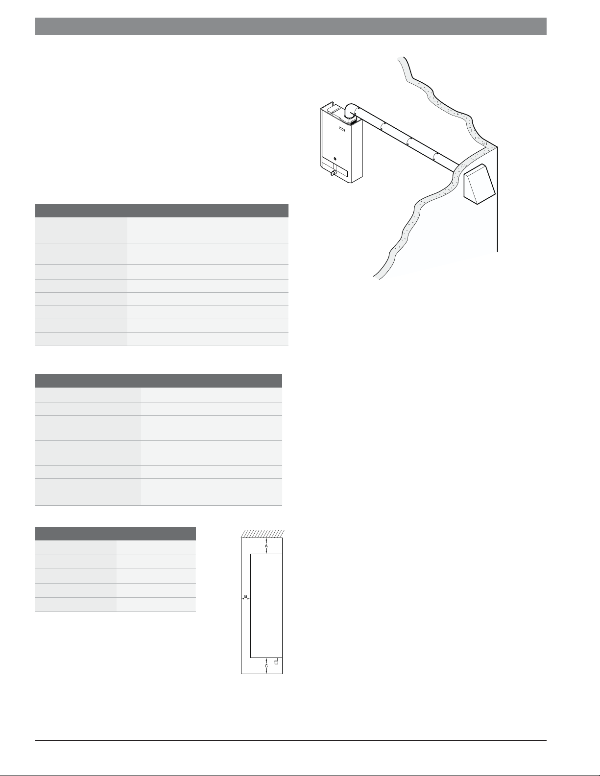
2.7 Bosch GWH 425 EF
Features:
Electronic ignition and built in power vent
Thermal effi ciency of 82%
Vents with 4" stainless steel or galvanized vent pipe
Specifically designed for horizontal vent terminations
Modulating gas valve — ensures temperature
stability
Model GWH 425 EF N for natural gas (NG) supply
Model GWH 425 EF L for liquid propane (LP) supply
15-year warranty
Qualifi es for $300 tax credit (LP only)
GWH 425 EF Technical Specifi cations
Gas input Natural Gas: 28,000 - 130,000 Btu/h
LP Gas: 28,000- 125,000 Btu/h
Minimum fl ow to
activate
Maximum fl ow rates 4.6 gpm @ 45°F rise
Thermal Effi ciency NG: 80% LP: 82%
Dimensions 29.75" h x 18.25" w x 8.75" d
Weight 44 lbs.
Modulating gas valve yes
Ignition Electronic
GWH 425 EF Installation Specifi cations
Gas connection ½" Male NPT
Water connections ½" Male NPT
NG gas pressure Minimum: 7" W.C.
LP gas pressure Minimum: 11" W.C.
Electrical supply 120VAC - plugs in
GWH 425 EF Installation Clearances
Top (A) 12"
Front (B) 4"
Back 0"
Sides 4"
Floor (C) 12"
0.5 gallons per minute (GPM)
Maximum: 14" W.C.
Maximum: 14" W.C.
Venting 4" stainless steel (AL29-4C)
or 26 gauge galvanized
| 11
Fig. 1 Venting confi gurations
Installation guidelines:
Venting:
4" AL29-4C sealed stainless steel or 26 gauge galvanized vent
pipe.
Slope horizontal runs up to termination ¼" per foot.
Do not combination vent with any other appliance.
See manual for vent terminator clearances.
Gas piping:
Heater will not function properly without adequate supply gas
pressure.
Any appliance connector should be ¾" minimum diameter
Plumbing:
Install the included pressure relief valve and pipe to suitable
drain.
Minimum piping diameter is ½".
Do not solder directly to connections on the bottom of the unit.
Use full port ball valves for isolation valves.
Applications manual | 11.2007Bosch Water Heating
Page 12
|
12
2.8 Bosch GWH 425 HN
Features:
Hydro-generated ignition
80% thermal effi ciency
Endless hot water for one major application at a time
Venting: 5" double wall B-vent — natural draft
Modulating gas valve — constant temperature at varying flow rates
Model GWH 425 HN N for natural gas (NG) supply
Model GWH 425 HN L for liquid propane (LP) supply
15-year warranty
Qualifi es for $300 tax credit
GWH 425 HN Technical Specifi cations
Gas input Natural Gas: 30,735 - 117,000 BTU
LP Gas: 30,735 - 117,000 BTU
Minimum fl ow to activate 0.6 gallons per minute (gpm)
Flow rates 45˚F rise @ 4.2 gpm
55˚F rise @ 3.4 gpm
65˚F rise @ 2.9 gpm
77˚F rise @ 2.4 gpm
90˚F rise @ 2.1 gpm
Thermal Effi ciency NG: 80% LP: 80%
Dimensions 25.75" h x 16.75" w x 8.5" d
Weight 33 lbs.
Modulating gas valve yes
Ignition Hydro-generated
Accessories Horizontal vent kit (AQ4) - power
vent kit for horizontal venting
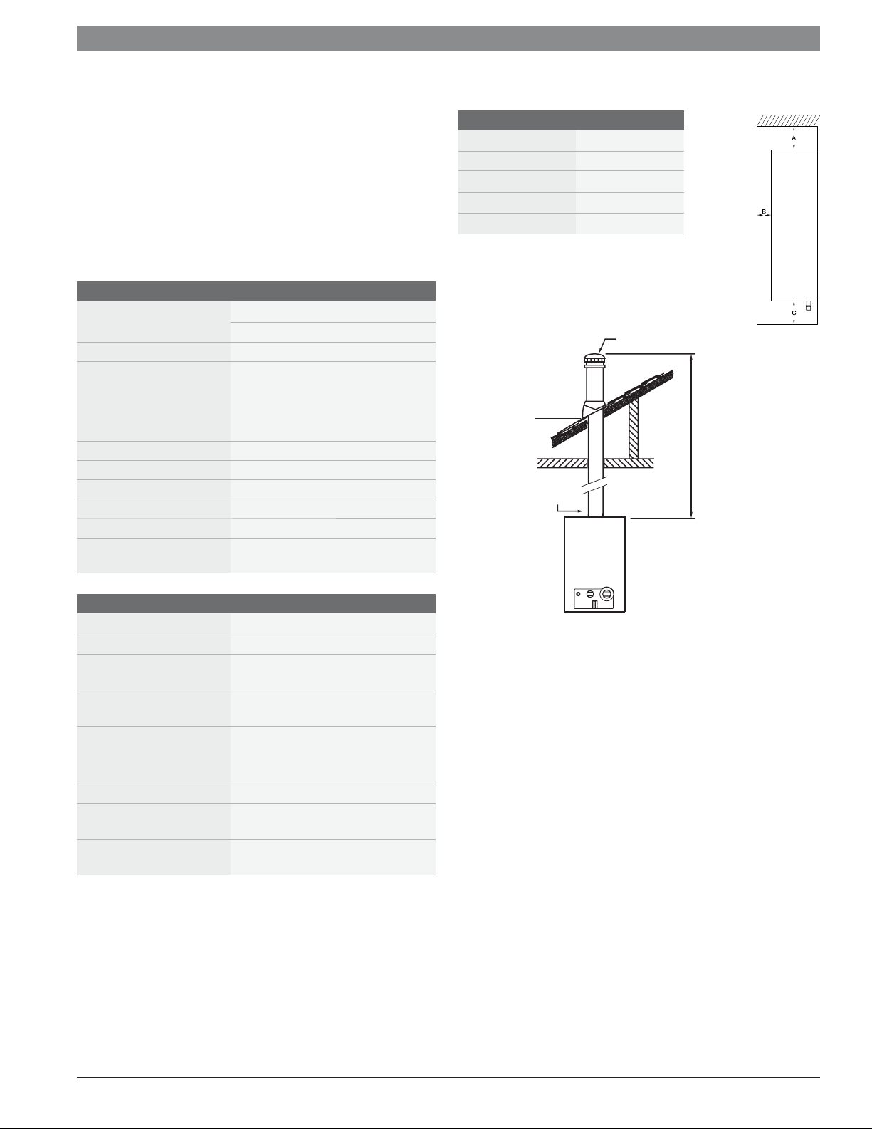
GWH 425 HN Installation Clearances
Top (A) 12"
Front (B) 4"
Back 0"
Sides 4"
Floor (C) 12"
LISTED GAS VENT
ESTABLISH A ONE
FOOT RISE BEFORE
ANY ELBOWS
LISTED VENT C AP
Applications manual
MINIMUM 6
FEE T (1.8M)
GWH 425 HN Installation Specifi cations
Gas connection ¾" Male NPT
Water connections ¾" Male NPT
NG gas pressure Minimum: 7" W.C.
Maximum: 14" W.C.
LP gas pressure Minimum: 11" W.C.
Maximum: 14" W.C.
Water pressure
(Static)
Minimum: 30 PSI
Minimum well pressure: 40 PSI
Maximum: 150 PSI
Electrical supply 120VAC - plugs in
Vertical venting 5" minimum diameter - natural
draft
Horizontal venting AQ4 horizontal vent kit required
for horizontal terminations
Fig. 2 Venting confi guration
Installation guidelines:
Venting:
5" minimum diameter — do not reduce vent size
Refer to installation manual for vent material options
Do not combination vent with any power vented appliances
Establish a one-foot rise before any elbows
Minimum vent height - 6 feet
Horizontal sections must slope upwards at least ¼" for every foot
of the horizontal length and be properly supported
Gas piping:
Heater will not function properly without adequate supply gas
pressure
Any appliance connector should be ¾" minimum diameter
Plumbing:
Install the included pressure relief valve and pipe to suitable drain
Minimum piping diameter is ¾"
Do not solder directly to connections on the bottom of the unit
Use full port ball valves for isolation valves
Application manual | 11.2007
Bosch Water Heating
Page 13
Applications manual
2.9 Bosch GWH 425 PN
Features:
Standing pilot ignition
78% thermal effi ciency
Endless hot water for one major application at a time
Modulating gas valve — constant temperature at varying flow rates
Model GWH 425 PN N for natural gas (NG) supply
Model GWH 425 PN L for liquid propane (LP) supply
15-year warranty
GWH 425 PN Technical Specifi cations
Power input Natural Gas: 31,000 - 117,000 BTU
LP Gas: 31,000 - 117,000 BTU
Minimum fl ow to activate 0.6 gallons per minute (gpm)
Flow rates 45˚F rise @ 4.2 gpm
55˚F rise @ 3.4 gpm
65˚F rise @ 2.9 gpm
77˚F rise @ 2.4 gpm
90˚F rise @ 2.1 gpm
Thermal Effi ciency NG: 78% LP: 78%
Dimensions 25.75" h x 16.75" w x 8.5" d
Weight 33 lbs.
Modulating gas valve yes
Ignition Standing pilot
Accessories Horizontal vent kit (AQ4) - power
vent kit for horizontal venting
GWH 425 PN Installation Clearances
Top (A) 12"
Front (B) 4"
Back 0"
Sides 4"
Floor (C) 12"
LISTED GAS VENT
ESTABLISH A ONE
FOOT RISE BEFORE
ANY ELBOWS
LISTED VENT C AP
| 13
MINIMUM 6
FEE T (1.8M)
GWH 425 PN Installation Specifi cations
Gas connection ¾" Male NPT
Water connections ¾" Male NPT
NG gas pressure Minimum: 7" W.C.
Maximum: 14" W.C.
LP gas pressure Minimum: 11" W.C.
Maximum: 14" W.C.
Water pressure Minimum: 30 PSI
Maximum: 150 PSI
Electrical supply 120VAC - plugs in
Vertical venting 5" minimum diameter - natural
draft
Horizontal venting AQ4 horizontal vent kit required
for horizontal terminations
Fig. 4 Venting confi guration
Installation guidelines:
Venting:
5" minimum diameter — do not reduce vent size.
Refer to installation manual for vent material options
Do not combination vent with any power vented appliances.
Establish a one-foot rise before any elbows
Minimum vent height - 6 feet.
Horizontal sections must slope upwards at least ¼" for every foot
of the horizontal length and be properly supported.
Gas piping:
Heater will not function properly without adequate supply gas
pressure.
Any appliance connector should be ¾" minimum diameter
Plumbing:
Install the included pressure relief valve and pipe to suitable
drain.
Minimum piping diameter is ¾".
Do not solder directly to the bottom of the unit.
Use full port ball valves for isolation valves.
Applications manual | 11.2007Bosch Water Heating
Page 14
|
14
2.10 Bosch GWH 260 PN
Features:
Standing pilot ignition
78% thermal effi ciency
Mounts on wall for easy installation
Venting: 4" double wall B-vent — natural draft
Modulating gas valve — constant temperature at varying flow rates
Model GWH 260 PN N for natural gas (NG) supply
Model GWH 260 PN L for liquid propane (LP) supply
15-year warranty
Applications manual
GWH 260 PN Installation Clearances
Top (A) 12"
Front (B) 4"
Back 0"
Sides 4"
Floor (C) 12"
GWH 260 PN Technical Specifi cations
Gas input Natural Gas: 30,735 - 74,900 BTU
LP Gas: 30,735 - 74,900 BTU
Minimum fl ow to activate 0.6 gallons per minute (gpm)
Flow rates 45˚F rise @ 2.6 gpm
55˚F rise @ 2.1 gpm
65˚F rise @ 1.7 gpm
77˚F rise @ 1.5 gpm
90˚F rise @ 1.3 gpm
Thermal Effi ciency NG: 78% LP: 78%
Dimensions 28.8" h x 12.2" w x 8.5" d
Weight 25 lbs.
Modulating gas valve yes
Ignition Standing pilot
GWH 260 PN Installation Specifi cations
Gas connection ¾" Male NPT
Water connections ¾" Male NPT
NG gas pressure Minimum: 7" W.C.
Maximum: 14" W.C.
LP gas pressure Minimum: 11" W.C.
Maximum: 14" W.C.
Water pressure
(Static)
Minimum: 30 PSI
Minimum well pressure: 40PSI
Maximum: 150 PSI
Electrical supply 120VAC - plugs in
Venting 4" double wall B-vent - natural
draft
LISTED VENT C AP
MINIMUM 6
FEE T (1.8M)
LISTED GAS VENT
ESTABLISH A ONE
FOOT RISE BEFORE
ANY ELBOWS
Fig. 4 Venting confi guration
Installation guidelines:
Venting:
4" minimum diameter — do not reduce vent size.
Refer to installation manual for vent material options
Do not combination vent with any power vented appliances.
Establish a one-foot rise before any elbows
Minimum vent height - 6 feet.
Horizontal sections must slope upwards at least ¼" for every foot
of the horizontal length and be properly supported.
Application manual | 11.2007
Gas piping:
Heater will not function properly without adequate supply gas
pressure.
Any appliance connector should be ¾" minimum diameter
Plumbing:
Install the included pressure relief valve and pipe to suitable
drain.
Minimum piping diameter is ¾".
Do not solder directly to the bottom of the unit.
Use full port ball valves for isolation valves.
Bosch Water Heating
Page 15
Applications manual
2.11 Powerstream Pro RP17PT, RP27PT
| 15
Features:
Over 90% effi ciency rating
10-year warranty on heat exchanger
Durable polymer construction
External temperature control knob
Thermal cut-out for safety
Flow sensor to provide a constant output temperature
Provides an ENDLESS supply of hot water
Weighs less than 25 pounds and fi ts virtually anywhere
No temperature/pressure relief valve necessary (unless required
by local codes)
Technical Specifi cations
Model RP17PT RP27PT
Effi ciency 90% 94%
Dimensions
15 ½" x 15 ¼" x 4 ½" 15 ½" x 15 ¼" x 4 ½"
Weight 20 lbs. 22 lbs.
Water fi ttings ¾" Male NPT ¾" Male NPT
Activation rate 0.6 gpm 0.8 gpm
Electrical requirements
Volts 240 240
Kilowatts 17.25kW 26.85kW
Amps
Wire
size
U.S.A
Canada
U.S.A
Canada
80 (2x40 amps)
80 (1x80 amps)
8 AWG
(4 conductors & ground)
Check Canadian
Electrical Code
(C22.1-02)
120 (3x40 amps)
120 (1x120amps)
8 AWG
(4 conductors & ground)
Check Canadian
Electrical Code
(C22.1-02)
Phase Single Single
Maximum fl ow rate at given temperature rise
45°F Rise 2.6 gpm 4.0 gpm
50°F Rise 2.3 gpm 3.7 gpm
60°F Rise 2.0 gpm 3.0 gpm
70°F Rise 1.7 gpm 2.6 gpm
80°F Rise 1.5 gpm 2.2 gpm
Installation guidelines:
Electrical:
Minimum electrical service for RP17PT is 150 amps.
Minimum electrical service for RP27PT is 200 amps.
Minimum wire size for both models is 8 AWG.
Plumbing:
Do not solder directly to connections on the bottom of the unit.
Use unions to facilitate easy future maintenance.
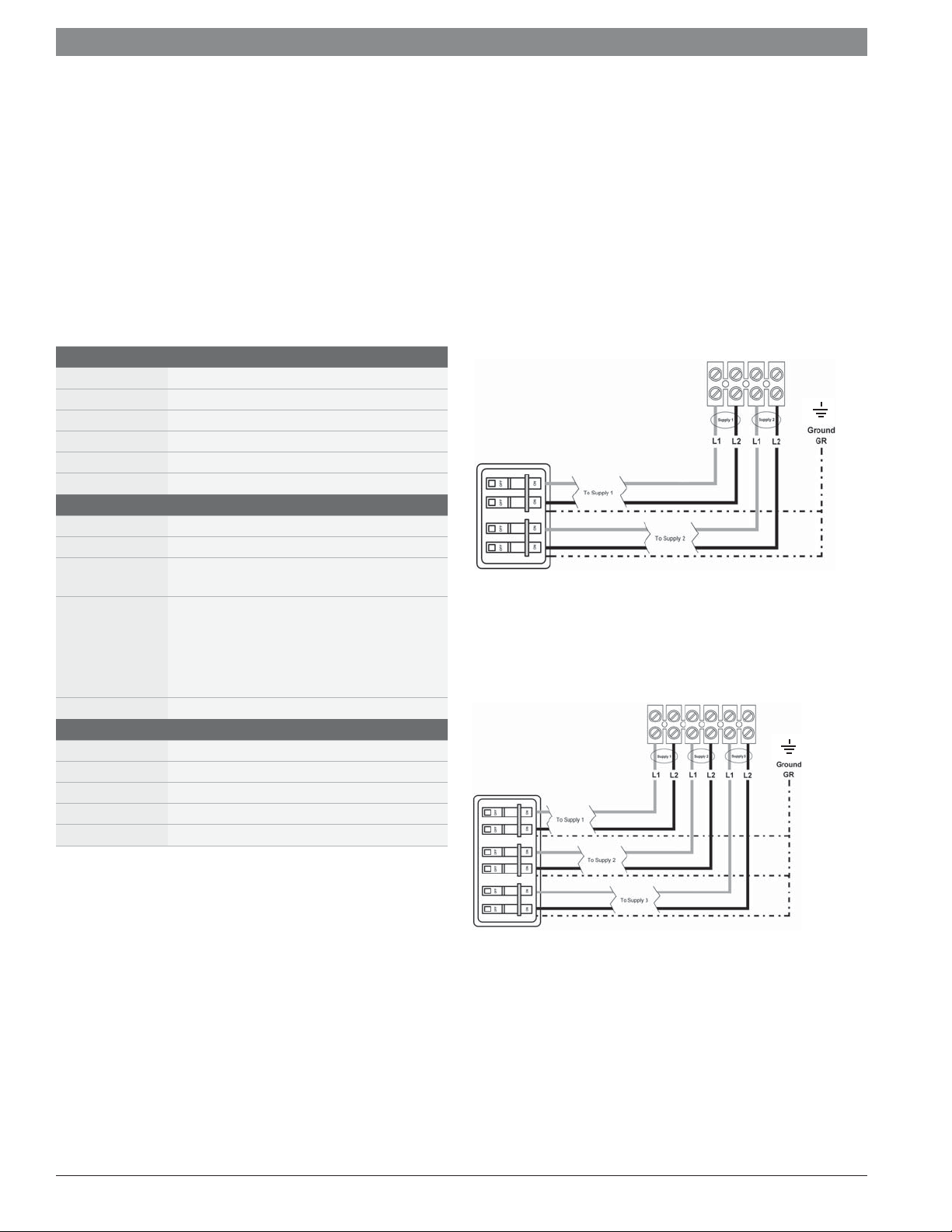
Use full port ball valves for isolation valves.
RP17PT terminal block
2 independent
40 amp double-pole
circuit breakers
Fig. 5 RP17PT Electrical Connections
RP27PT terminal block
3 independent
40 amp double-pole
circuit breakers
Fig. 6 RP27PT Electrical Connections
Applications manual | 11.2007Bosch Water Heating
Page 16

16
|
Applications manual
2.12 Powerstream Pro RP1P, RP2P, RP3P, RP7P,
RP9P,RP12PT
Installation guidelines:
Features:
5-year warranty on heat exchanger
Saves space
Installs vertically or horizontally (Model RP12PT only installs
horizontally)
All models must be hardwired
Solid copper heat exchanger, copper sheathed elements and
tough plastic housing
High/low kW settings possible within most models
Model RP12PT has thermostatic adjustable control
Technical Specifi cations
Model Part # Wire Size Voltage Amps High kW Low kW Degree rise at fl ow rates (GPM)* Activation
RP1P 8AWG 240 40 9.50 — — 84° 64° 42° 32° 0.75
20 — 4.75 — 42° 32° 21° 16°
RP2P 10AWG 277 22 6.00 — 81° 55° 42° 27° — 0.50
11 — 3.00 41° 28° 21° 14° —
RP3P 10AWG 120 29 3.40 — 41° 28° 20° — — 0.50
RP7P 10AWG 240 30 7.20 — — 63° 48° 32° 24° 0.75
15 — 3.60 — 32° 24° 16° 12°
RP9P 8AWG 277 35 9.50 — — 84° 64° 42° 32° 0.75
18 — 4.75 — 42° 32° 21° 16°
RP12PT 6AWG 240 50 12.00 — — 90° 72° 52° 42° 0.75
Electrical:
Refer to the chart below as specifi cation varies by model
Plumbing:
Do not solder directly to connections on the bottom of the unit.
Use unions to facilitate easy future maintenance.
Use full port ball valves for isolation valves.
0.5 0.75 1.0 1.5 2.0
rate (GPM)
Application manual | 11.2007
Bosch Water Heating
Page 17

Applications manual
| 17
2.13 Ariston Pro GL2.5Ti, GL4Ti, GL8Ti
Features:
Point of use mini tank
3 models
Adjustable thermostat with thermal cut-out
Dielectric isolation on inlet/outlet connections
Units can be wall hung (bracket included) or fl oor mounted
Durable poly-composite housing will not dent and resists corrosion
Temperature/pressure relief valve included (plumb correctly for
Installation guidelines:
Electrical:
Follow local codes for electrical outlets for water heaters
All models plugin to standard wall outlet.
Plumbing:
Use full port valves for isolation valves.
Do not solder directly to the plumbing connections.
discharge)
Simple 120V AC plug-in connection
8-year warranty
Technical Specifi cations
GL2.5Ti GL4Ti GL8Ti
Tank Volume 2.75 gallons 3.85 gallons 7.0 gallons
Nominal Dimensions 14" x 14" x 11" 14" x 14" x 14" 17 ½" x 17 ½" x 14 ½"
Voltage 120V 120V 120V
Amperage 12.5 amps 12.5 amps 12.5 amps
Wire Type Plug-in Plug-in Plug-in
Heating Capacity 1500 watts 1500 watts 1500 watts
Recovery at 90° rise 7 gph 7 gph 7gph
Temperature range 65-145°F 65-145°F 65-145°F
Water connections ½" NPT ½" NPT ¾" NPT
Maximum water
150 PSI 150 PSI 150 PSI
pressure
Relief valve Installed Installed Included
Applications manual | 11.2007Bosch Water Heating
Page 18

|
18
3 Domestic Water Heating Applications
Potable water
Potable water is water that is suitable for drinking. Bosch Water
Heating appliances are approved to heat potable water only. Heating
any other liquid other than potable water will void the manufactures
warranty covering the appliance.
Introduction
This chapter covers the various application techniques Bosch Water
Heating recommends. The schematics are to be used by professional
contractors in designing a domestic water heating system. The
applications covered range from single sink point-of-use applications
to multi-appliance central domestic recirculation applications.
3.1 Point-of-use applications
Point-of-use applications cover the small applications that a large
water heater would be ineffi cient for. Installing a smaller heater at a
point-of-use puts the heater near the hot water demand and reduces
the wait for hot water. Common applications for these appliances
include homes, offi ces, warehouses, service stations, stores, conces-
sion stands, and summer camps.
Applications manual
Application manual | 11.2007
Bosch Water Heating
Page 19

Applications manual
3.1.1 Ariston mini tank
Simply tap into the cold water line and install the water heater
directly at the sink. All models plug into a standard 120 volt outlet.
Heater can be wall mounted, or sit on the fl oor.
| 19
Ariston Pro GL2.5 Ti
Ariston Pro GL8 Ti
hot
cold cold
hot
Ariston Pro GL4 Ti
hot
cold
Symbols
Temperature and pressure
relief valve
Sink
Flow direction
Service valve
Drain pan
Note: This drawing is conceptual in nature and does not address all design, installation or safety considerations.
Additional safety and/or auxiliary equipment may be needed. This diagram is for reference use by officials, designers and licensed installers.
It is expected that installers have adequate knowledge of accepted industry practices for the equipment, procedures, and applications involved.
Drawing is not to scale.
Drawing # POU1
Applications manual | 11.2007Bosch Water Heating
CN rev 06/06
Page 20

|
20
3.1.2 Powerstream Pro electric point-of-use tankless water heater
PowerstreamPro point-of-use water heaters come in four models to
serve a wide range of applications. Finding the right model depends
upon your desired temperature and fl ow rate. Use the table below to
fi nd the model best suited to your customer‘s needs. Flow controls
and faucet aerators can greatly enhance performance.
Note: Water heater must be fi lled with water and purged of air prior
to supplying power.
hot
Applications manual
cold supply
Powerstream Pro
RP1P, RP2P, RP3P,
RP7P, RP9P, RP12PT
hot
cold supply
cold
Symbols
Service valve
hot
Powerstream Pro
RP1P, RP2P, RP3P,
RP7P, RP9P, RP12PT
cold
Sink
hot
Flow direction
Note: This drawing is conceptual in nature and does not address all design, installation or safety considerations.
Additional safety and/or auxiliary equipment may be needed. This diagram is for reference use by officials, designers and licensed installers.
It is expected that installers have adequate knowledge of accepted industry practices for the equipment, procedures, and applications involved.
Drawing is not to scale.
Drawing # POU2
CN rev 06/07
Application manual | 11.2007
Bosch Water Heating
Page 21

Applications manual
BOSCH
3.1.3 Bosch GWH-260PN gas tankless water heater
The Bosch GWH-260PN gas tankless water heater offers
a compact and lightweight design for easy installation.
This unit is equipped with standing pilot ignition and is
intended for low volume applications.
Bosch GWH 260 PN
| 21
Symbols
Temperature and pressure
relief valve
hot
cold
Sink
Low flow
Service valves
Flow direction
shower
Note: This drawing is conceptual in nature and does not address all design, installation or safety considerations.
Additional safety and/or auxiliary equipment may be needed. This diagram is for reference use by officials, designers and licensed installers.
It is expected that installers have adequate knowledge of accepted industry practices for the equipment, procedures, and applications involved.
Drawing is not to scale.
Drawing # POU3
CN rev 06/07
Applications manual | 11.2007Bosch Water Heating
Page 22

|
22
3.2 Whole house applications
Whole house applications cover the typical home applications up to
a 2 or 3 bedroom house. See the sizing guide (Section 2.1) to
determine the best Bosch water heater model for your application.
An enhanced design including an Ariston mini tank in line to the hot
water source will reduce the wait time for hot water and improve
temperature stability.
3.2.1 Powerstream Pro whole house applications
The RP17PT and RP27PT must be hard wired directly to the breaker
box.
Applications manual
Powerstream Pro
RP17PT or RP27PT
ColdHot
Ariston Pro GL4Ti
for pipe runs over
100 ft, use GL8Ti
Note: place Ariston close to the point of
use to reduce wait time for hot water.
Powerstream Pro
RP17PT or RP27PT
Hot
Cold
Symbols
Standard tub fixture
Flow direction
Service
valves
Sink
Note: Cold water piping to fixtures not shown for clarity purposes.
Note: This drawing is conceptual in nature and does not address all design, installation or safety considerations.
Additional safety and/or auxiliary equipment may be needed. This diagram is for reference use by officials, designers and licensed installers.
It is expected that installers have adequate knowledge of accepted industry practices for the equipment, procedures, and applications involved.
Drawing is not to scale.
Application manual | 11.2007
Drawing # WH1
Bosch Water Heating
CN rev 06/07
Page 23

Applications manual
3.2.2 Powerstream Pro whole house application with domestic
recirculation loop
The circulator should be controlled by an external aquastat, or with
a timer to run only during times of expected hot water usage.
| 23
Powerstream Pro
RP17PT or RP27PT
Hot
Cold
Ariston Pro GL4Ti
(for pipe runs over
100ft use GL8Ti)
Symbols
Bronze circulator pump sized
according to UPC standards
(Taco Bronze 007 or Grundfos 15-42B
will cover most homes up to 3 bathrooms)
Potable water
expansion tank
Note: Cold water piping to fixtures not shown for clarity purposes.
Note: This drawing is conceptual in nature and does to address all design, installation or safety considerations.
Additional safety and/or auxiliary equipment may be needed. This diagram is for reference use by officials, designers and licensed installers.
It is expected that installers have adequate knowledge of accepted industry practices for the equipment, procedures, and applications involved.
Drawing is not to scale.
Flow check valve
Service
valves
Timer or
Aquastat
Sink
Flow direction
Standard tub fixture
Drawing # WH1R
CN rev 06/07
Applications manual | 11.2007Bosch Water Heating
Page 24

|
24
3.2.3 Bosch ProTankless gas water heater
Below are two examples of Bosch ProTankless gas water heater
installations for the whole house. One example shows an Ariston
mini tank in line for reduced hot water wait time and increased
temperature stability.
Applications manual
Bosch GWH 715 ES,
Bosch GWH C 800 ES,
Bosch GWH 425 HN or
Bosch GWH 425 PN
Ariston Pro GL4Ti
for pipe runs over
100 ft, use GL8Ti
Note: place Ariston close to the point of
use to reduce wait time for hot water.
Symbols
Standard tub fixture
Pressure
Flow
direction
relief
valve
Hot
Bosch GWH 715 ES,
Bosch GWH C 800 ES,
Bosch GWH 425 HN or
Bosch GWH 425 PN
Hot
Cold
Cold
Service
Sink
valves
Note: Cold water piping to fixtures not shown for clarity purposes.
Note: This drawing is conceptual in nature and does not address all design, installation or safety considerations.
Additional safety and/or auxiliary equipment may be needed. This diagram is for reference use by officials, designers and licensed installers.
It is expected that installers have adequate knowledge of accepted industry practices for the equipment, procedures, and applications involved.
Drawing is not to scale.
Application manual | 11.2007
Drawing # WH2
CN revA 10/07
Bosch Water Heating
Page 25

Applications manual
3.2.4 Bosch ProTankless gas water heater with domestic
recirculation loop
The circulator should be controlled by an external aquastat, or with
a timer to run only during times of expected hot water usage.
| 25
Ariston Pro GL4Ti
(for pipe runs over
100ft use GL8Ti)
Potable water
expansion tank
Bronze circulator sized
according to UPC standards
(Taco Bronze 007 or Grundfos 15-42B
will cover most homes up to 3 bathrooms)
Flow
check
valve
Symbols
Service
valves
Pressure
relief
valve
Sink
Timer or
Aquastat
Hot
Cold
Bosch GWH 715 ES,
Bosch GWH C 800 ES,
Bosch GWH 425 HN or
Bosch GWH 425 PN
Standard
tub
fixture
Flow direction
Note: Cold water piping to fixtures not shown for clarity purposes.
Note: This drawing is conceptual in nature and does not address all design, installation or safety considerations.
Additional safety and/or auxiliary equipment may be needed. This diagram is for reference use by officials, designers and licensed installers.
It is expected that installers have adequate knowledge of accepted industry practices for the equipment, procedures, and applications involved.
Drawing is not to scale.
Drawing # WH2R
Applications manual | 11.2007Bosch Water Heating
CN rev 06/07
Page 26

|
26
4 High Volume Potable Water Heating
Potable water
Potable water is water that is suitable for drinking. Bosch Water
Heating appliances are approved to heat potable water only. Heating
any other liquid other than potable water will void the manfuctures
warranty covering the appliance.
Introduction
This section lays out the options for high volume water heating for
large residential and light commercial applications including continuous fl ows and high volume demands of large home and
commercial applications.
4.1 Parallel unit applications
Parallel unit applications have twice the activation rate of single unit
applications. The following designs are for continuous fl ow, high
volume hot water needs. Not intended for residential use. To balance fl ows use reverse return piping. (shown below)
Applications manual
Application manual | 11.2007
Bosch Water Heating
Page 27

Applications manual
4.1.1 Bosch ProTankless gas water heater in parallel for
commercial applications
Two Bosch ProTankless units will have double the activation rate of a
single unit. When sizing gas line, ensure the gas line is sized to carry
the BTU load of two units plus any additional gas appliances. See
the installation manuals for a gas line sizing chart.
Bosch GWH 715 ES,
Bosch GWH C 800 ES,
*see text above about
activation rate and
gas supply requirements
| 27
hot
cold
hot
cold
Symbols
Pressure
relief
valves
cold
hot
Note: This drawing is conceptual in nature and does not address all design, installation or safety considerations.
Additional safety and/or auxiliary equipment may be needed. This diagram is for reference use by officials, designers and licensed installers.
It is expected that installers have adequate knowledge of accepted industry practices for the equipment, procedures, and applications involved.
Drawing is not to scale.
Flow direction
Service
valves
Drawing # P2
CN revA 10/07
Applications manual | 11.2007Bosch Water Heating
Page 28

|
28
4.2 Cascading unit applications
A cascading application should be considered if the potential hot
water demand exceeds the capacity of one GWH 715 ES or
GWH C 800 ES. The cascading set up supports variable fl ow inputs
and is designed for large homes and commercial applications.
4.2.1 GWH 715 ES and GWH C 800 ES cascading
Cascading allows up to two appliances to be connected in parallel.
One of the appliances will serve as the controlling Master appliance
and will attempt to meet the hot water demand. If the hot water
demand is beyond the capacity of the Master appliance, a signal is
sent to the Slave appliance to begin operation.
hot
cold
tankless link
hot
cold
Applications manual
Bosch GWH 715 ES or
Bosch GWH C 800 ES
• The plumbing must be connected in the reverse
return method with a minimum number of elbows
to aid in balancing pressures between the two
appliances.
• If a domestic recirculation system is desired,
recirculate the water through the Ariston ProTi
water heater as seen in chapter 3.4.
• Locate appliances close together for
improved performance.
• Follow industry plumbing practices when installing
multiple appliances
• Minimum pipe diameter: ¾"
• Minimum water pressure: 50 psi
• Maximum distance between appliances: 36"
• Insulate pipes to prevent heat loss.
cold
hot
Ariston Pro GL8Ti
outlet
inlet
Symbols
Water
hammer
arrestor
Flow direction
Pressure
relief
valve
recommended
Service
valves
Note: This drawing is conceptual in nature and does not address all design, installation or safety considerations.
Additional safety and/or auxiliary equipment may be needed. This diagram is for reference use by officials, designers and licensed installers.
It is expected that installers have adequate knowledge of accepted industry practices for the equipment, procedures, and applications involved.
Drawing is not to scale.
Drawing # CA1
Tankless
link
CN revA 10/07
Application manual | 11.2007
Bosch Water Heating
Page 29
Applications manual
4.3 External storage tank loading applications.
Introduction
This section lays out tank loading options for high volume water
heating for large residential and light commercial applications
including continuous fl ows and high volume demands of large home
and commercial applications.
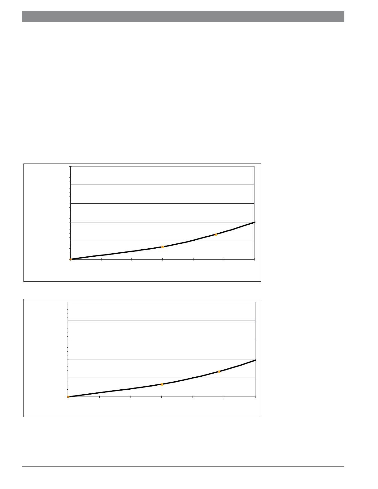
4.3.1 GWH 345/450 ESR pressure drops and circulator guidelines
The maximum amp draw for any circulator connected directly to
the appliance must not exceed 1.5 amps
Circulator should be sized by the professional plumbing
contractor
Bronze or stainless steel circulators required for all open loop
applications
50 feet of head
40 feet of head
| 29
30 feet of head
20 feet of head
10 feet of head
Inlet pressure
0 feet of hea d
50 feet of head
40 feet of head
30 feet of head
20 feet of head
10 feet of head
GWH 345 ESR
0 GPM 1 GPM 2 GPM 3 GPM 4 GPM 5 GP M 6 GPM
water flow rate
GWH 450 ESR
Inlet pressure
0 feet of head
0 GPM 1 GPM 2 GP M 3 GPM 4 GPM 5 GPM 6 GPM
water flow rate
Pressure drop curves
Note : Flow above 6 GPM is not permitted.
Applications manual | 11.2007Bosch Water Heating
Page 30

|
30
4.3.2 Single unit tank loading application plumbing diagram
The GWH 345/450 ESR is specifi cally designed for this application.
Cold water
feed
DHW
Bosch GWH 345 ESR,
Bosch GWH 450 ESR
Applications manual
PS
Symbols
Potable water
expansion tank
Pressure
relief
Flow
direction
valve
Bronze circulator sized
according to UPC standards
Service
valves
12K ohm
thermistor
with immersion
well
Note: Piping to fixtures not shown for clarity purposes.
Note: This drawing is conceptual in nature and does not address all design, installation or safety considerations.
Additional safety and/or auxiliary equipment may be needed. This diagram is for reference use by officials, designers and licensed installers.
It is expected that installers have adequate knowledge of accepted industry practices for the equipment, procedures, and applications involved.
Drawing is not to scale.
Drawing # STL
External
storage
tank
CN revA 10/07
Application manual | 11.2007
Bosch Water Heating
Page 31

Applications manual
4.3.2 Single unit tank loading application electrical diagram
The following shows the appropriate electrical connections for
plumbing diagram 4.3.2
Terminal box
PK
L N
P0
LL PSN L
| 31
110VAC from outlet
PE
ESR control
board
PS
PCB
Single Unit Tank Loading
Electrical Diagram
Note: This drawing is conceptual in nature and does not address all design, installation or safety considerations.
Additional safety and/or auxiliary equipment may be needed. This diagram is for reference use by officials, designers and licensed installers.
It is expected that installers have adequate knowledge of accepted industry practices for the equipment, procedures, and applications involved.
Drawing is not to scale.
Drawing # ESTL
Applications manual | 11.2007Bosch Water Heating
CN revA 10/07
Page 32

|
Thermostatic
mixing
valve
32
5 Open Loop Space Heating
Introduction
This section is designed to provide a road map of techniques for
using a tankless water heater to heat domestic water and at the
same time provide space heating in residential applications. As with
all installations, check with the local authority having jurisdiction.
Some jurisdictions may not allow these types of applications.
Cold water
feed
Applications manual
5.1 External storage tank
The appliances shown in this section are approved under ANSI
Z21.10.3 and CSA 4.3 as circulating gas water heaters. Only open
loop applications are approved under this standard.
5.1.1 Radiant space heating and DHW plumbing diagram
Bosch GWH 345 ESR,
DHW
Bosch GWH 450 ESR
P2
Potable water
expansion tank
Bronze circulator
sized according to
UPC standards
P1
Symbols
Pressure
relief
valve
Thermostatic
mixing
valve
Flow
direction
Service
valves
Radiant
piping
12K ohm
thermistor
with immersion
well
PS
Storage
tank
Note: Piping to fixtures not shown for clarity purposes.
Note: This drawing is conceptual in nature and does not address all design, installation or safety considerations.
Additional safety and/or auxiliary equipment may be needed. This diagram is for reference use by officials, designers and licensed installers.
It is expected that installers have adequate knowledge of accepted industry practices for the equipment, procedures, and applications involved.
Drawing is not to scale.
Application manual | 11.2007
Drawing # ROL
Bosch Water Heating
CN revA 10/07
Page 33

Applications manual
5.1.1 Radiant space heating and DHW electrical diagram
The following shows the appropriate electrical connections for
plumbing diagram 5.1.1
Terminal box
PK
L N
P0
LL PSN L
| 33
110VAC from outlet
PE
ESR control
board
Neutral
120Vac
24 VAC
POWER
T
Stat
SR 502
TWO ZONE SWITCHING RELAY
FUSE 1 AMP
NPZCHX1 ZR
P1
ZONE1 ZONE2
X
2
ZONE1 ZONE2
PS
T
Stat
P2
Radiant Space Heating and DHW
Electrical Diagram
PCB
Note: This drawing is conceptual in nature and does not address all design, installation or safety considerations.
Additional safety and/or auxiliary equipment may be needed. This diagram is for reference use by officials, designers and licensed installers.
It is expected that installers have adequate knowledge of accepted industry practices for the equipment, procedures, and applications involved.
Drawing is not to scale.
Drawing # EROL
Applications manual | 11.2007Bosch Water Heating
CN revA 10/07
Page 34

|
34
5.1.2 Fan coil space heating and DHW plumbing diagram
Fan Coil
Cold water
P1
feed
DHW
Applications manual
Bosch GWH 345 ESR,
Bosch GWH 450 ESR
Potable water
expansion tank
Air
seperator
Bronze circulator
sized according to
UPC standards
Symbols
Flow
check
valve
Pressure
relief
valve
Thermostatic
mixing
valve
Service
valves
Fan Coil
Tank
Aquastat
PK
Storage
tank
Flow
direction
Note: Piping to fixtures not shown for clarity purposes.
Note: This drawing is conceptual in nature and does to address all design, installation or safety considerations.
Additional safety and/or auxiliary equipment may be needed. This diagram is for reference use by officials, designers and licensed installers.
It is expected that installers have adequate knowledge of accepted industry practices for the equipment, procedures, and applications involved.
Drawing is not to scale.
Application manual | 11.2007
Drawing # FCOL
CN revA 10/07
Bosch Water Heating
Page 35

Applications manual
5.1.2 Fan Coil space heating and DHW electrical diagram
The following shows the appropriate electrical connections for plumbing diagram 5.1.2
Terminal box
PK
L N
P0
LL
PS
N L
PE
ESR control
| 35
110VAC from outlet
board
PK
T
Stat
Neutral
120Vac
SR501
1 ZONE
SWITCHING RELAY
120 VAC
INPUT
H3 5
4
N/O4N/C6N/ONN/C
24
WR
VAC
COM
TT
6
TT
LR LS
AQUASTAT
P1
Fan Coil Space Heating and DHW
Electrical Diagram
Note: This drawing is conceptual in nature and does not address all design, installation or safety considerations.
Additional safety and/or auxiliary equipment may be needed. This diagram is for reference use by officials, designers and licensed installers.
It is expected that installers have adequate knowledge of accepted industry practices for the equipment, procedures, and applications involved.
Drawing is not to scale.
Drawing # EFCOL
CN revA 10/07
Applications manual | 11.2007Bosch Water Heating
Page 36

|
36
5.1.3 Baseboard/ Radiant Panel space heating and DHW plumbing diagram
Cold water
feed
P1
DHW
Applications manual
Bosch GWH 345 ESR,
Bosch GWH 450 ESR
Potable water
expansion tank
Air
seperator
Bronze circulator
sized according to
UPC standards
Symbols
Flow
check
valve
Pressure
relief
valve
Thermostatic
Mixing
valve
Flow
direction
Tank
Aquastat
Service
valves
Baseboard/
Radiant
Panel
PK
Storage
tank
Note: Piping to fixtures not shown for clarity purposes.
Note: This drawing is conceptual in nature and does not address all design, installation or safety considerations.
Additional safety and/or auxiliary equipment may be needed. This diagram is for reference use by officials, designers and licensed installers.
It is expected that installers have adequate knowledge of accepted industry practices for the equipment, procedures, and applications involved.
Drawing is not to scale.
Application manual | 11.2007
Drawing # BB OL
Bosch Water Heating
CN revA 10/07
Page 37

Applications manual
5.1.3 Baseboard/Radiant Panel space heating and DHW electrical diagram
The following shows the appropriate electrical connections for plumbing diagram 5.1.3
Terminal box
PK
L N
P0
LL
PS
N L
PE
ESR control
| 37
110VAC from outlet
board
Neutral
120Vac
24 VAC
POWER
PK
T
Stat
SR 503
or equivalent
FUSE 1 AMP
NPZCHX
P1
ZONE1 ZONE2 ZONE3
THREE ZONE SWITCHING RELAY
WITH OPTIONAL PRIORITY
X2
1 ZR
ZONE1 ZONE2 ZONE3
Baseboard Space Heating and DHW
Electrical Diagram
TT
LR LS
AQUASTAT
Note: This drawing is conceptual in nature and does not purport to address all design, installation or safety considerations.
Additional safety and/or auxiliary equipment may be needed. This diagram is for reference use by officials, designers and licensed installers.
It is expected that installers have adequate knowledge of accepted industry practices for the equipment, procedures, and applications involved.
Drawing is not to scale.
Drawing # EBBOL
Applications manual | 11.2007Bosch Water Heating
CN revA 10/07
Page 38

|
38
5.1.4 Baseboard/ Radiant Panel space heating and DHW (with Ariston mini tank) plumbing diagram
Bosch GWH 345 ESR,
Bosch GWH 450 ESR
PK
Applications manual
DHW
Ariston GL8Ti
mini water
tank
Bronze circulator
sized according to
UPC standards
Cold water
feed
Flow
check
valve
Pressure
relief
valve
Thermostatic
mixing
valve
Symbols
PS
Cold water
Potable
water
expansion tank
Aquastat
well & 12kohm
thermistor
Service
valves
feed
Aquastat
well with
12k ohm
thermistor
(insulate piping
around thermistor)
Baseboard/
Radiant
Panel
Flow
direction
Note: Piping to fixtures not shown for clarity purposes.
Note: This drawing is conceptual in nature and does not address all design, installation or safety considerations.
Additional safety and/or auxiliary equipment may be needed. This diagram is for reference use by officials, designers and licensed installers.
It is expected that installers have adequate knowledge of accepted industry practices for the equipment, procedures, and applications involved.
Drawing is not to scale.
Application manual | 11.2007
Drawing # BBAOL
Bosch Water Heating
CN revA 10/07
Page 39

Applications manual
5.1.4 Baseboard/Radiant Panel space heating and DHW (with Ariston mini tank) electrical diagram
The following shows the appropriate electrical connections for plumbing diagram 5.1.4
Terminal box
PK
L N
P0
LL
PS
N L
PE
ESR control
board
| 39
110VAC from outlet
PK
PS
PCB
TT
LR LS
Room Thermostat
Baseboard/Radiant Panel Space Heating and DHW (with Ariston mini tank)
Electrical Diagram
Note: This drawing is conceptual in nature and does not address all design, installation or safety considerations.
Additional safety and/or auxiliary equipment may be needed. This diagram is for reference use by officials, designers and licensed installers.
It is expected that installers have adequate knowledge of accepted industry practices for the equipment, procedures, and applications involved.
Drawing is not to scale.
Drawing # EBBAOL
Applications manual | 11.2007Bosch Water Heating
CN revA 10/07
Page 40

|
40
5.1.5 Baseboard/ Radiant Panel space heating and DHW (without storage tank) plumbing diagram
Bosch GWH 345 ESR,
Bosch GWH 450 ESR
Applications manual
PK
DHW
Cold water
feed
Piping
Insulation
Bronze circulator
sized according to
UPC standards
PS
Symbols
Flow
check
valve
Pressure
relief
valve
Thermostatic
mixing
valve
Insulate
piping
Flow
direction
Aquastat
well & 12kohm
thermistor
Service
valves
Baseboard/
Radiant
Panel
Note: Piping to fixtures not shown for clarity purposes.
Note: This drawing is conceptual in nature and does not address all design, installation or safety considerations.
Additional safety and/or auxiliary equipment may be needed. This diagram is for reference use by officials, designers and licensed installers.
It is expected that installers have adequate knowledge of accepted industry practices for the equipment, procedures, and applications involved.
Drawing is not to scale.
Application manual | 11.2007
Drawing # BBNTOL
Bosch Water Heating
CN revA 10/07
Page 41

Applications manual
5.1.5 Baseboard/Radiant Panel space heating and DHW (without storage tank) electrical diagram
The following shows the appropriate electrical connections for plumbing diagram 5.1.5
Terminal box
PK
L NP0LL PSN L
PE
ESR control
board
| 41
110VAC from outlet
PK
PS
PCB
Baseboard/Radiant Panel Space Heating and DHW
Without Storage Tank Electrical Diagram
Note: This drawing is conceptual in nature and does not address all design, installation or safety considerations.
Additional safety and/or auxiliary equipment may be needed. This diagram is for reference use by officials, designers and licensed installers.
It is expected that installers have adequate knowledge of accepted industry practices for the equipment, procedures, and applications involved.
Drawing is not to scale.
Drawing # BBNTOL
Applications manual | 11.2007Bosch Water Heating
CN revA 10/07
Page 42

|
42
5.2 Indirect Tank Applications
5.2.1 Indirect Baseboard/ Radiant Panel space heating and DHW plumbing diagram
Note: Not suitable for space heating applications requiring high water temperature.
Cold water
feed
Applications manual
Bosch GWH 345 ESR,
Bosch GWH 450 ESR
DHW
Potable water
expansion tank
Air
seperator
P1
Flow
check
valve
Pressure
relief
valve
Symbols
Flow
direction
Tank
Aquastat
Indirect
hot water
tank
Cold
feed
PK
Baseboard/
Radiant
Panel
Bronze circulator
sized according to
UPC standards
Note: Piping to fixtures not shown for clarity purposes.
Note: This drawing is conceptual in nature and does not address all design, installation or safety considerations.
Additional safety and/or auxiliary equipment may be needed. This diagram is for reference use by officials, designers and licensed installers.
It is expected that installers have adequate knowledge of accepted industry practices for the equipment, procedures, and applications involved.
Drawing is not to scale.
Application manual | 11.2007
Thermostatic
Mixing
valve
Service
valves
Pressure
reducing
valve
Drawing # IDBBOL
Back Flow
preventer
Bosch Water Heating
CN revA 10/07
Page 43

Applications manual
5.2.1 Baseboard/Radiant Panel space heating and DHW electrical diagram
The following shows the appropriate electrical connections for plumbing diagram 5.2.1
Terminal box
PK
L N
P0
LL
PS
N L
PE
ESR control
| 43
110VAC from outlet
board
Neutral
120Vac
24 VAC
POWER
PK
T
Stat
SR 503
or equivalent
FUSE 1 AMP
NPZCHX
P1
Indirect Baseboard/Radiant Panel Space Heating and DHW
Electrical Diagram
ZONE1 ZONE2 ZONE3
THREE ZONE SWITCHING RELAY
WITH OPTIONAL PRIORITY
X2
1 ZR
ZONE1 ZONE2 ZONE3
TT
LR LS
AQUASTAT
Note: This drawing is conceptual in nature and does not address all design, installation or safety considerations.
Additional safety and/or auxiliary equipment may be needed. This diagram is for reference use by officials, designers and licensed installers.
It is expected that installers have adequate knowledge of accepted industry practices for the equipment, procedures, and applications involved.
Drawing is not to scale.
Drawing # EID BBOL
Applications manual | 11.2007Bosch Water Heating
CN revA 10/07
Page 44

44
|
Applications manual
6 Maintenance Drawings
Bosch appliances are designed to last for many years. In order to keep the heater operating properly, periodic maintenance is required.
Please consult the installation manual for maintenance intervals. A descaling procedure drawing is included to assist in clearing the water
heater of mineral deposits that may build up over time.
6.1 Descaling procedure
This procedure should only be done if there is evidence of scale build-up such as a reduced hot water fl ow rate or if the water is known to
have high levels of minerals such as calcium.
1. Disconnect electrical supply from the water heater.
2. Shut off the water supply to the water heater using (installer supplied) isolation valve.
3. Open hot water taps to drain and relieve pressure from the plumbing system.
4. Drain water from the unit’s heat exchanger by disconnecting inlet and outlet water connections.
5. Connect the line (A) from the outlet of the circulating pump (installer supplied) to the inlet water fi tting on the water heater.
6. Using another line (B), connect to the water outlet fi tting on the water heater. Route the other end of this line into a descaling reser-
voir.
7. Using a 3rd line (C) from the descaling reservoir, connect to the inlet side of circulating pump. Verify there is a fi lter on the end of the
line in the descaling reservoir.
8. Make sure all connections are “hand tight.”
9. Fill tank with descaling solution so lines inside are submersed. We recommend a straight white vinegar. If using a commercial descalant,
refer to manufacturer’s instructions for proper dilution ratio.
11. Operate the circulating pump.
12. Make sure there are no leaks and the solution is fl owing from the descaling reservoir through the heat exchanger and returning to the
reservoir.
13. Run solution through the heat exchanger until the solution returning to the descaling reservoir comes out clear. (Changing to a fresh
solution may be necessary during this process)
14. Disconnect all lines and drain all solution from heat exchanger. Properly discard of solution.
15. Position a container below the hot water outlet and connect cold water supply. Open cold water supply isolation valve and fl ush heat
exchanger with clean water.
16. Shut cold water isolation valve and reconnect hot water supply to the water heater.
17. Reconnect electrical supply to unit, open water isolation valves, and return the unit to service.
Application manual | 11.2007
Bosch Water Heating
Page 45

Applications manual
6.1 Descaling procedure diagram
B
| 45
Bosch GWH 715 ES,
Bosch GWH C 800 ES,
Bosch GWH 425 HN or
Bosch GWH 425 PN
Symbols
Circulating
pump
Flow direction
C
A
Filter
Service
valves
Note: This drawing is conceptual in nature and does not purport to address all design, installation or safety considerations.
Additional safety and/or auxiliary equipment may be needed. This diagram is for reference use by officials, designers and licensed installers.
It is expected that installers have adequate knowledge of accepted industry practices for the equipment, procedures, and applications involved.
Drawing is not to scale.
Drawing # MD1
CN revA 10/07
Applications manual | 11.2007Bosch Water Heating
Page 46

46
|
Applications manual
Application manual | 11.2007
Bosch Water Heating
Page 47

Applications manual
| 47
Applications manual | 11.2007Bosch Water Heating
Page 48

48
|
Applications manual
Application manual | 11.2007
Bosch Water Heating
Page 49

Applications manual
| 49
Applications manual | 11.2007Bosch Water Heating
Page 50

BBT North America Corporation
Bosch Group
Bosch Water Heating
50 Wentworth Ave
Londonderry, NH 03053
Telephone (603) 882-1100
Fax (603) 584-1681
www.protankless.com
techsupport@protankless.com
 Loading...