

Bosch GWH 345 ESR-N, GWH 345 ESR-L, GWH 450 ESR-L, GWH 450 ESR-N User Manual
GWH 345/450 ESR
Temperature Modulated with Electronic Ignition
Suitable for heating recirculating potable water
GWH-345/450-ESR-N - Natural Gas
GWH-345/450-ESR-L - Liquefied Petroleum (LP) Gas
6 720 607 909 US (2008.07) JS
Warning: If the information in this manual is not
followed exactly, a fire or explosion may result
causing property damage, personal injury or death.
Do not store or use gasoline or other flammable
vapor and liquids in the vicinity of this or any other
appliance.
Improper installation, adjustment, alteration,
service or maintenance can cause injury or
property damage. Refer to this manual. For
assistance or additional information consult a
qualified installer, service agency or the gas
supplier.
In the Commonwealth of Massachusetts this
product must be installed by a licensed plumber or
gas fitter.
Upon completion of the installation, these
instructions should be handed to the user of the
appliance for future reference.
What to do if you smell gas
• Close gas valve. Open windows and doors, and
evacuate the building.
• Do not try to operate any appliance.
• Do not touch any electrical switch; do not use any
phone in your building
• Immediately call your gas supplier from a neighbor’s
phone. Follow the gas supplier’s instructions.
• If you cannot reach your gas supplier, call the fire
department.
• Installation and service must be performed by a
qualified installer, service agency or the gas supplier.
6 720 607 909
2
Index
Index
1Warning 2
2 Appliance details 4
2.1 Features 4
2.2 GWH-345/450-ESR Specifications (Technical data) 4
2.3 Unpacking the GWH-345/450-ESR heater 5
2.4 General rules to follow for safe operation 6
2.5 Dimensions and minimum installation clearances 7
2.6 Applications 8
2.7 Water quality 9
3 Installation instructions 10
3.1 Introduction 10
3.2 Proper location for installing your heater 10
3.3 Heater placement and clearances 10
3.4 Mounting installation 10
3.5 Combustion air requirements 11
3.6 Venting 13
3.6.1 Vent material and specifications 13
3.6.2 Vent connections and combustion air inlet restrictors 14
3.6.3 Condensate drain requirements 17
3.6.4 Room sealed installation (Twin pipe) 17
3.6.5 Vertical terminations 18
3.6.6 Horizontal terminations 18
3.6.7 Exhaust vent configuration examples 22
3.7 Gas piping & connections 23
3.8 Measuring gas pressure 25
3.9 Checking restrict. plate size by measuring CO
2
level value 26
3.10 Water connections 26
3.11 Electrical connections 27
4 Operating instructions 28
4.1 Initial filling instructions 28
4.2 For your safety read before operating your water heater 28
4.3 Startup instructions 28
4.4 Power 29
4.5 Recirculating water temperature 29
4.6 Temperature and hot water flow 29
4.7 Freeze protection 29
4.8 Electrical diagram 30
5 Maintenance and service 31
5.1 Diagnostic mode 31
6 Altitude adjustments 33
7 Troubleshooting 34
8 GWH-345/450-ESR Functional scheme 36
9 Interior components diagram and parts list 37
9.1 Interior components 37
9.2 Components diagram 38
9.3 Parts list 39
10 Protecting the environment 40
11 Ten Year Limited Warranty 41
1 Warning
For your safety
Do not store or use gasoline or other flammable,
combustible or corrosive vapors and liquids in the
vicinity of this or any other appliance.
Warning: Carefully plan where you
install the heater. Correct combustion
air supply and flue pipe installation are
very important. If a gas appliance is not
installed correctly, fatal accidents can
result from lack of air, carbon monoxide
poisoning or fire.
Warning: Exhaust gas must be vented
to outside using 3" single wall sealed
stainless steel vent pipe suitable for
category III vent systems and
temperatures up to 480°F. Vent and
combustion air connector piping must
be sealed gas-tight to prevent
possibility of flue gas spillage, carbon
monoxide emissions and risk of fire,
resulting in severe personal injury or
death.
Warning: Place the recirculating water
heater in a location where water leaks
will NOT DAMAGE adjacent areas or
lower floors.
Warning: Field wiring connections and
electrical grounding must comply with
local codes, or in the absence of local
codes, with the latest edition of the
National Electric Code, ANSI/NFPA 70,
or in Canada, all electrical wiring must
comply with the local codes and the
Canadian Electrical Code, CSA C22.1
Part 1.
Warning: Shock hazard line voltage is
present. Before servicing the
recirculating water heater, turn off the
electrical power to the recirculating
water heater at the main disconnect or
circuit breaker. Failure to do so could
result in severe personal injury or death.
6 720 607 909
Warning
3
FCC:
This device complies with Part 15 of the FCC rules.
Operation is subject to the following two conditions: (1)
This device may not cause harmful interference, and (2)
this device must accept any interference received,
including interference that may cause undesired operation.
Fig. 1
Warning: The recirculating water
heater must be disconnected from the
gas supply piping system during any
pressure testing of that system at test
pressures equal to or more than 0.5
psig (14” W.C.).
Warning: The recirculating water
heater should be located in an area
where leakage of the tank or
connections will not result in damage to
the area adjacent to the appliance or to
lower floors of the structure. When such
locations cannot be avoided, it is
recommended that a suitable drain pan,
adequately drained, be installed under
the appliance. The pan must not restrict
combustion air flow.
Warning: The maximum inlet gas
pressure must not exceed the value
specified by the manufacturer and that
the minimum value listed is for the
purposes of input adjustment.
Warning: If a water heater is installed in
a closed water supply system, such as
one having a backflow preventer in the
cold water supply line, means shall be
provided to control thermal expansion.
Contact the water supplier or local
plumbing inspector on how to control
this situation.
Warning: Keeping appliance area clear
and free from combustible materials,
gasoline and other flammable vapors
and liquids.
Warning: Not obstructing the flow of
combustion and ventilation air.
Warning: When manually operating the
relief valve, precautions must be taken
prior to operating the relief valve to avoid
contact with hot water coming out of the
relief valve and to prevent water
damage.
Caution: Label all wires prior to
disconnection when servicing controls.
Wiring errors can use improper and
dangerous operation.
Verify proper operation after servicing.
Warning: If a relief valve discharges
periodically, this may be due to thermal
expansion in a closed water supply
system. Contact the water supplier or
local plumbing inspector on how to
correct this situation. Do not plug the
relief valve.
Caution: Any changes or
modifications not expressly approved
by the party responsible for compliance
could void the user’s authority to
operate the equipment.

6 720 607 909
4
Appliance details
2 Appliance details
2.1 Features
Parts
• Sealed combustion burner.
Safety
• Ionization flame sensor
• Over temperature protection.
High quality materials for long working life
• Copper heat exchanger
• Compact space saver: mounts on a wall with
supplied bracket.
Features
• LCD screen to display temperatures, burner
operation and error codes
• On/Off button and separate temperature controls for
domestic water heating and recirculating water
• Reset button
• Failure codes for diagnostics and repair
• Freeze prevention cycle.
2.2 GWH-345/450-ESR Specifications
(Technical data)
Approved in US/Canada
Capacity
GWH345 Maximum flow rate: 3.5 GPM (13 l/min) at a
45°F (25°C) rise.
GWH450 Maximum flow rate: 4.5 GPM (17 l/min) at a
45°F (25°C) rise.
Maximum output
GWH345 - 77,900 Btu/h (22.8 kW)
GWH450 - 98,400 Btu/h (28.8 kW)
Maximum input
GWH345 - 95,000 Btu/h (27.8 kW)
GWH450 - 120,000 Btu/h (35.1 kW)
(3 to 1 Modulation)
Efficiency in %
GWH345 Combustion efficiency: 82%
GWH450 Combustion efficiency: 81%
Min. Output
GWH345 - 23,900 Btu/h (7 kW)
GWH450 - 35,500 Btu/h (10.4 kW)
Temperature Control
Selection range: 113°F (45°C) - 194°F (90°C)
Gas Requirement
Gas connection (inches) - ¾”
Inlet gas pressure under operation (with a high hot
water flow rate)*
• Propane: 11” - 13” water column
• Natural Gas: 5.5” - 10.5” water column.
* To measure gas pressure, see Measuring Gas
Pressure, chapter 3.8.
Venting
3" AL 29-4C single wall sealed stainless steel vent
pipe.
See chapter 3.6 for Venting.
Water
• Hot water connection - ¾” NPT
• Cold water connection - ¾” NPT.
Combustion
•NOx ≤ 100 ppm
•CO ≤ 250 ppm
•CO
2
level (see table 8 for correct restrictor
dimension).
Dimensions
• Depth (in): 11 ¾” (300 mm)
• Width (in): 15 ¾” (400 mm)
• Height (in): 27 ½” (700 mm)
• Weight: 47 pounds (21 kg).
Gas types
Natural Gas.
Liquid Propane.
The appliance is not field convertible.
Voltage
120 V AC (50/60 Hz)
Amperage
Idle - 40 mA
Operation - ≤ 1.5 A
Noise
≤ 50 db (A)
Safety devices
• Flame failure device (Ionization flame control)
• Overheat prevention (temperature limiter)
• Pressure switch (blocked vent protection).
i
BOSCH is constantly improving its
products, therefore specifications are
subject to change without prior notice.
6 720 607 909
Appliance details
5
Water resistant
IP X4 (protection against water drops)
2.3 Unpacking the GWH-345/450-ESR
heater
This heater is packed securely.
The box includes:
• Wall-mounted gas fired recirculating water heater
• Bracket and screws for wall hanging the heater (Part
No. 8708003143)
• Exhaust vent adaptor (with 4 screws and gasket
provided) (Part No. 8705504149)
• Combustion air inlet adaptor (with 4 screws and
gasket provided) (Part No. 8705504148)
• Installation manual
• Product registration card
• Energy Guide label
• Pressure relief valve (Part No. BP1000A150)
• Inlet air restrictors
– GWH 345 ESR N: Ø38/40/42
– GWH 345 ESR LP: Ø38/40/42
– GWH 450 ESR N: Ø44/47/50/55
– GWH 450 ESR LP: Ø47/50/55/60
Do not lose this manual. Please complete and return
the enclosed product registration card.
Before installing the unit, be certain you have the
correct heater for your type of Gas - Propane or
Natural Gas. Identification labels are found on the
shipping box, and on the rating plate which is located on
the right side panel of the cover.
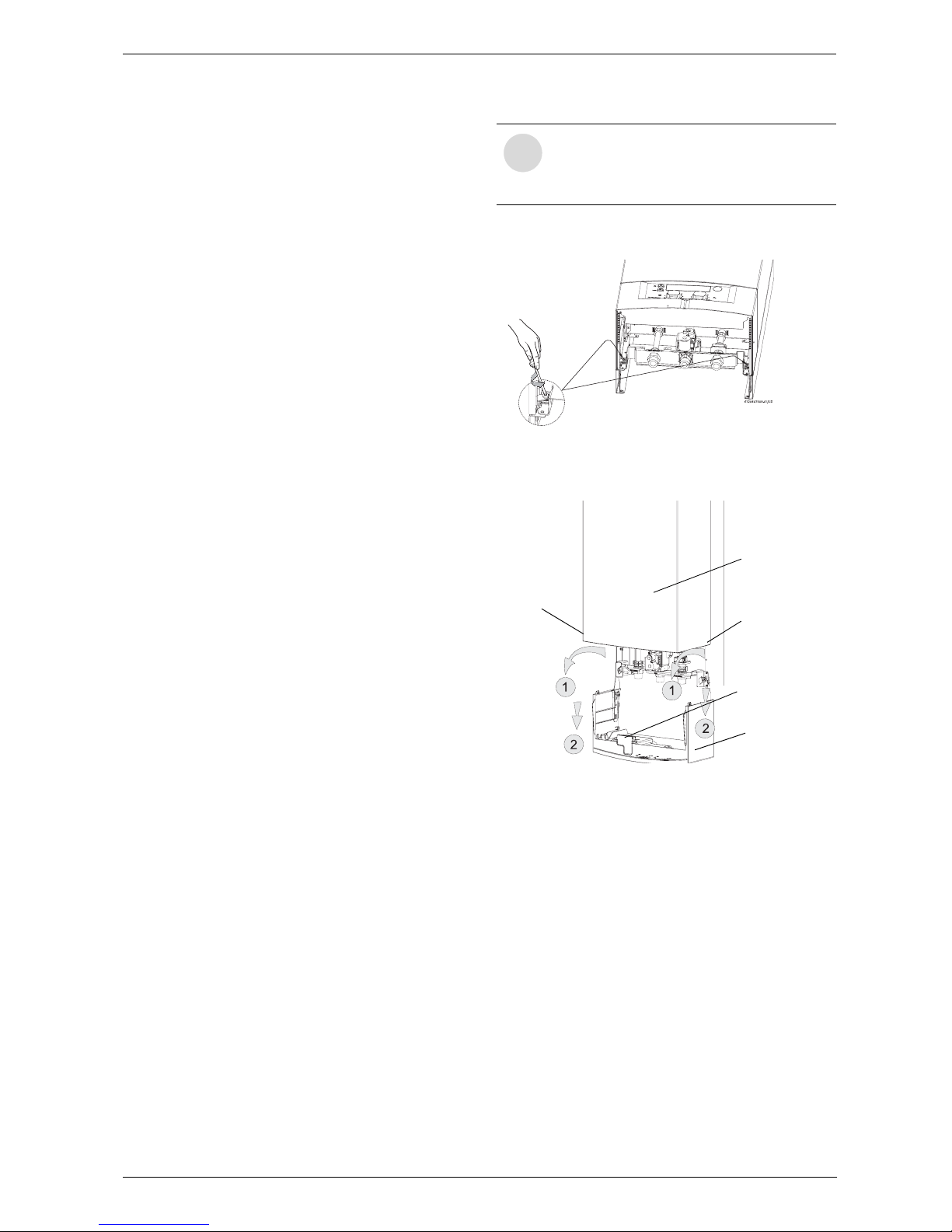
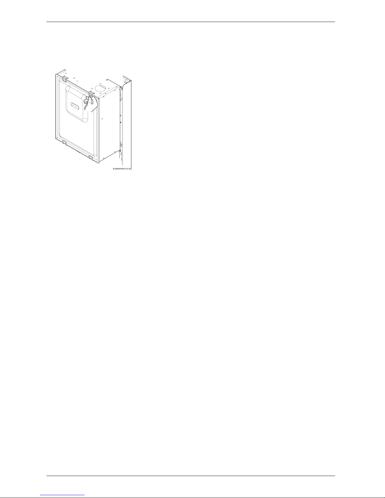
To remove front cover
B Loosen the two Philips head screws located as
shown in fig. 2.
Fig. 2 Screws
B Pull control panel outwards and then pull it down-
wards (Fig. 3).
Fig. 3 Service position to access water and electric
connections
B Lift front cover upward and remove.
B Remove cover screws.
i
The front cover is secured with two
screws to prevent unauthorized access.
Always secure the control panel and front
cover with these screws.
Front cover
Control panel
Low voltage
access cover
Cover screw
Cover screw
6 720 607 909
6
Appliance details
To remove combustion cover (service only)
B Open the four clips and remove the combustion
cover.
Fig. 4 Remove the combustion cover
The GWH-345/450-ESR is not approved or
designed for:
• Manufactured (mobile) homes, RV's or boats.
(Modular homes are acceptable for installation).
• Outdoor installation
• Combination venting with other appliances
• Closed loop heating applications
• Use above 8,000 ft A.S.L. altitude.
2.4 General rules to follow for safe
operation
1. You must follow these instructions when you install
your heater. In the United States: The installation
must conform with local codes or, in the absence of
local codes, the National Fuel Gas Code ANSI
Z223.1/NFPA 54.
In Canada: The Installation must conform with CGA
B149.(1,2) INSTALLATION CODES and /or local
installation codes.
2. Carefully plan where you install the heater. Correct
combustion air supply and vent pipe installation are
very important. If not installed correctly, fatal
accidents can be caused by lack of air, carbon
monoxide poisoning or fire.
3. When the unit is installed indoors with ROOM
SEALED (twin pipe) combustion air and venting, it is
permitted to be located in bathrooms, bedrooms and
occupied rooms that are normally kept closed. See
chapter 3.6. If the unit will be installed indoors and
use indoor combustion air, the place where you
install the heater must have enough ventilation. The
National Fire Codes do not allow UNSEALED gas
fired water heater installations in bathrooms,
bedrooms or any occupied rooms normally kept
closed. See chapter 3.2 and 3.5.
4. You must vent your heater. See chapter 3.6 Venting.
5. The appliance and its gas connection must be leak
tested before placing the appliance in operation. The
appliance must be isolated from the gas supply
piping system by closing its individual manual gas
shutoff valve (not supplied with heater) during any
pressure testing at pressures in excess of ½ Psig
(3.5 kPa).
6. Keep water heater area clear and free from
combustibles and flammable liquids. Do not locate
the heater over any material which might burn.
7. Correct gas pressure is critical for the optimum
operation of this heater. Gas piping must be sized to
provide the required pressure at the maximum output
of the heater, while all the other gas appliances are in
operation. Check with your local gas supplier, and
see the section on connecting the gas supply.
8. Should overheating occur or the gas supply fails to
shut off, turn off the gas supply at the manual gas
shut off valve, on the gas line. Note: manual gas
shutoff valve is not supplied with the heater.
9. Do not use this appliance if any part has been
underwater. Immediately call a qualified service
technician to inspect the appliance and to replace
any part of the control system and any gas control
which has been underwater.
10. Failure to install heater correctly may lead to unsafe
operation and void the warranty.
11. If the heater is installed in an area where
temperatures are below 42°F, the heater will activate
to prevent freezing. The piping outside the
appliance will not be protected. See Chapter 4.7
for additional freeze prevention information.
12. In areas where water supply has a high mineral
content, a water softener is strongly recommended.
A water softener is required if the water hardness
exceeds 6 grains/gal (103 mg/l) calcium carbonate.
Damage to the water heater resulting from hard
water/scale deposits will not be covered under
warranty.
6 720 607 909
Appliance details
7
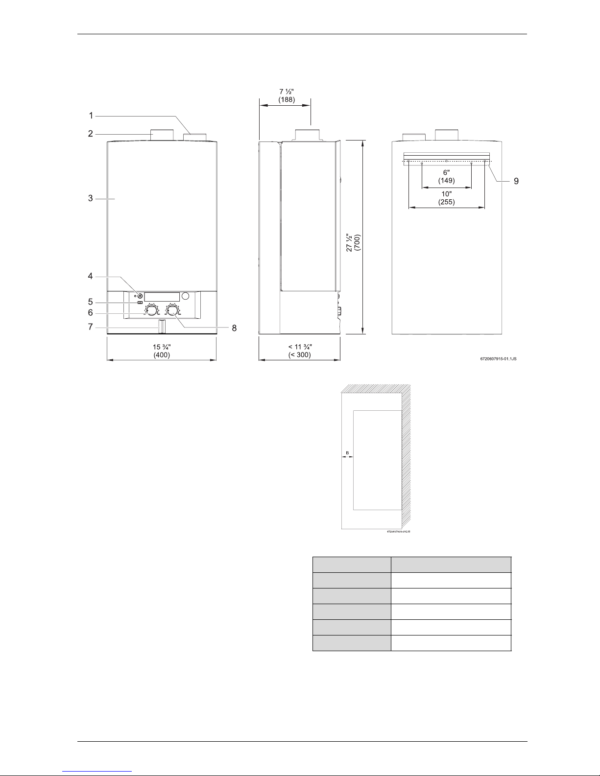
2.5 Dimensions and minimum installation clearances
Fig. 5 Dimensions
1 Combustion air inlet adapter (right side only)
2 Exhaust adapter with CO
2
measuring point
3 Front cover
4 On/Off button
5 Reset button
6 Recirculating water temperature selector
7 LED - (ON) warning light (blinks when in error lock out)
8 Domestic hot water temperature selector
9 Mounting bracket
Fig. 6 Minimum clearances
Model GWH-345/450-ESR
TOP 12”
FRONT (B) 4”
BACK 0”
SIDES ½”
BOTTOM 12”
Table 1 Minimum clearances
6 720 607 909
8
Appliance details
2.6 Applications
Introduction
The application designs provided in this manual are general guides to be used when installing this recirculating water
heater.
Pump Sizing
Required PS pumps are Taco 007 Bronze or Grundfos 15-42B. PZ pumps should be sized by a professional plumbing contractor based on the specific application.
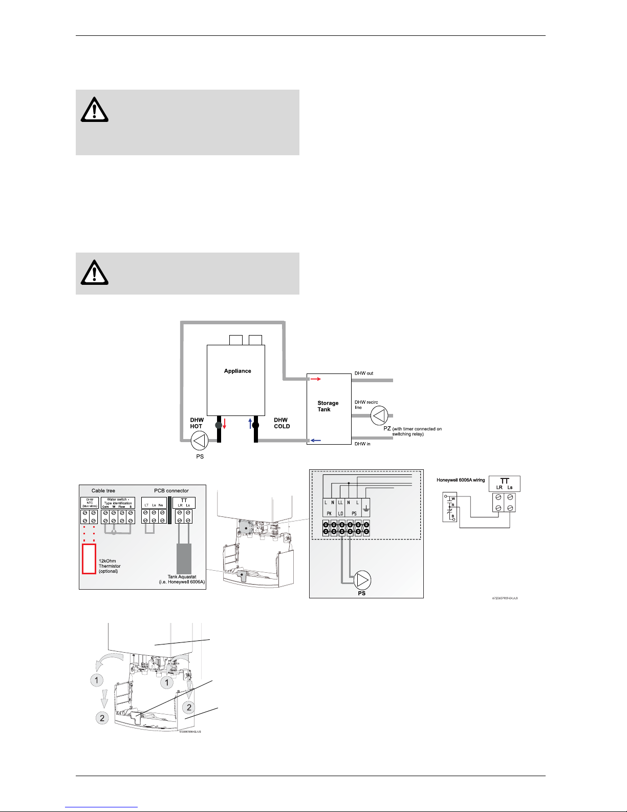
Instantaneous water heater (direct tank load design)
Fig. 7
Fig. 8 Service position to access water and electric
connections
Caution: the water heater which will be
used to supply potable water shall not
be connected to any heating system or
component(s) previously used with a
nonpotable water heating appliance.
Caution: Do not overpump the heater.
Maximum 5 gpm water flow permitted
through the heater.
Note: maximum amp draw:
1.5A. Do not connect
additional pump to the
appliance but use a relay panel
if powering multiple pumps.
Front cover
Control panel
Low voltage
access cover
6 720 607 909
Appliance details
9
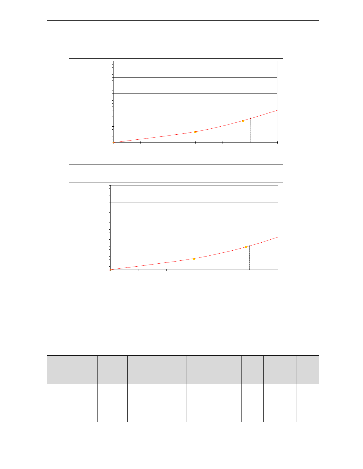
Pressure drop curves
Note: Flow above 5 GPM is not permitted.
Fig. 9 GWH 345 ESR
Fig. 10 GWH 450 ESR
2.7 Water quality
Water quality can have an impact on appliance performance and appliance longevity, and may not be covered by the
manufacturer's warranty.
For water analysis data call your local water department. If on a well system, have well water analyzed periodically. If
water quality is exceeding one or more of the values specified below, Bosch recommends installing a water conditioner or softener.
GWH 345 ESR
0 feet of head
10 feet of head
20 feet of head
30 feet of head
40 feet of head
50 feet of head
0 GPM 1 GPM 2 GPM 3 GPM 4 GPM 5 GPM 6 GPM
water flow rate
Inlet pressure
GWH 450 ESR
0 feet of head
10 feet of head
20 feet of head
30 feet of head
40 feet of head
50 feet of head
0 GPM 1 GPM 2 GPM 3 GPM 4 GPM 5 GPM 6 GPM
water flo w rate
Inlet pressure
Description
pH TDS
(Total
Dissolved
Solids)
Total
hardness
Aluminum Chlorides Copper Iron Manganese Zinc
Max.
Levels
pH
range
mg/l or
ppm
mg/l or
ppm
mg/l or
ppm
mg/l or
ppm
mg/l or
ppm
mg/l or
ppm
mg/l or ppm mg/l or
ppm
6.5-8.5 500 100 (6
grains)
0.2 250 1.0 0.3 0.05 5.0
Table 2 Water Quality Specifications
6 720 607 909
10
Installation instructions
3 Installation instructions
3.1 Introduction
Please follow these instructions. Failure to follow
instructions may result in:
• Property damage or personal injury
•Improper operation
• Heater damage
• Loss of warranty.
Please contact Bosch Water Heating with any
questions.
3.2 Proper location for installing your
heater
Carefully select the location of the water heater. For
your safety and for proper heater operation, you must
provide combustion air to the heater and a proper
exhaust vent system.
Follow the guidelines below:
B 1. Locate the heater where venting, gas and
plumbing connections are feasible and convenient.
B 2. The hot water lines should be kept short to save
energy. Centrally locating the water heater is best. It
is always best to have hot water lines insulated.
3.3 Heater placement and clearances
The GWH-345/450-ESR is design certified for
installation on a combustible wall (see 3.4 Mounting
installation) provided the floor covering below the
heater is noncombustible. For installations in an alcove
or closet, maintain the minimum clearances to
combustible and non-combustible materials listed
below. See also fig. 6.
A. Top 12 inches (305 mm)
B. Front 4 inches (100 mm)
C. Back 0 inches
D. Sides ½ inches (12 mm)
E. Bottom 12 inches (305 mm)
Clearances from any exhaust vent pipe are dependent
upon the clearance requirements of the stainless steel
vent pipe manufacturer. Single wall sealed stainless
steel (AL29-4C) vent pipe (rated for Category III
appliances) must be used when exhaust venting this
appliance. See 3.6 Venting.
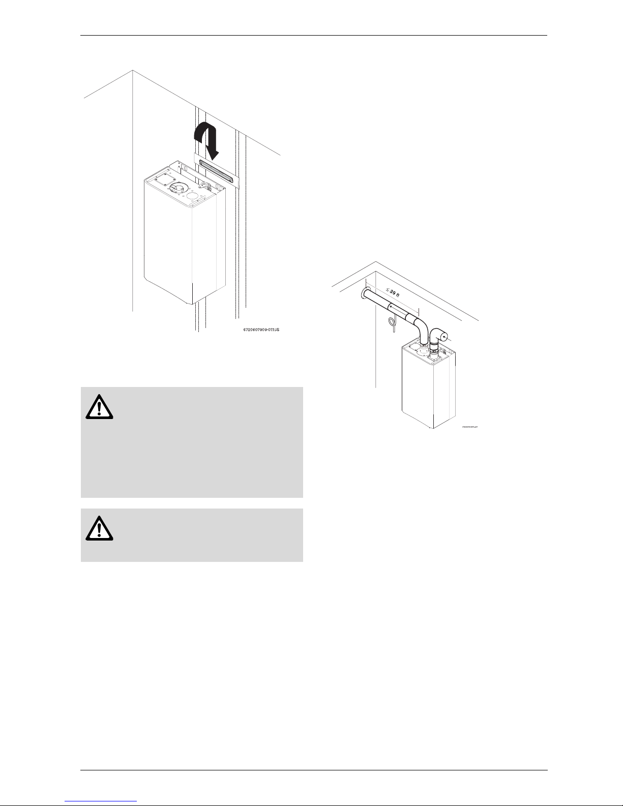
3.4 Mounting installation
B Secure the wall mounting bracket provided with the
heater to a wall surface.
If wall is a stud wall sheathed with plaster or drywall, it
is recommended that support board(s), either 1x4’s or
1/2" (minimum) plywood first be attached across a pair
of studs. Then attach the heater’s bracket to the upper
support board. The heater should be kept level on the
wall surface. See Fig. 11.
Warning: The water in this
recirculating water heater is cold and
always remains cold except for the
times the burners are on. In the event of
power outage in conjunction with
freezing temperatures, it is
recommended that the heater be
drained to prevent heater from freezing.
See chapter 10 for draining
instructions.
Warning: Flammable materials,
gasoline, pressurized containers, or any
other items or articles that are potential
fire hazards must NOT be placed on or
adjacent to the heater. The appliance
area must be kept free of all
combustible materials, gasoline and
other flammable vapors and liquids.
Warning: before starting installation:
B check that there are no loose parts
inside the appliance
B check that the gas type of the heater
matches the gas supply you will be
connecting to the heater.
B ensure that gas pipe, gas valve, fan and
burner have no damage and are properly fitted.
i
Front cover should be removed (see
instructions on page 5) in order to inspect
components visually.
Warning: Do not install this appliance
on a carpeted wall. The heater must be
mounted on a wall using appropriate
anchoring materials.
6 720 607 909
Installation instructions
11
Fig. 11 Mounting the heater
3.5 Combustion air requirements
Twin pipe
The GWH-345/450-ESR is designed as a sealed
combustion appliance. It is recommended that the
combustion air be provided by a dedicated 3” pipe to
the outside. If terminating combustion air piping
horizontally, pitch vent down 1/4" per foot towards
termination to prevent rain from entering the appliance.
The combustion air pipe may be constructed of
aluminum flex, PVC or any other rigid or semi rigid
sealed pipe. The combustion air inlet must be located in
such a manner as to provide a minimum 3 foot distance
from the exhaust vent terminator.
The maximum length of the combustion air inlet is 39
feet with one elbow. Subtract 3 feet for each additional
90° elbow and 1.5 feet for each 45° elbow. Maximum
number of elbows permitted is 4 (see Table 6).
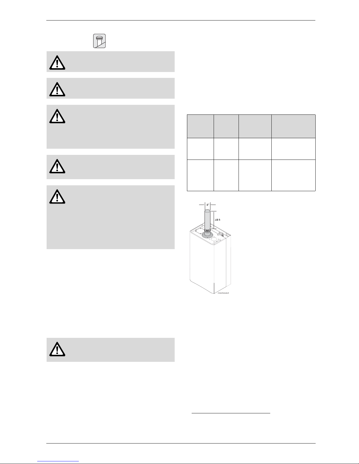
Single pipe
Note: This appliance requires 6200 cubic feet of
available combustion air, or a minimum of 775 square
feet of space with an 8 foot ceiling to operate. If the
large amount of air space, which equates to about half
of most average sized homes, is not available, the
appliance must pull air from outside (see twin pipe
system above).
Although it is permissible to draw combustion air from
inside the structure, it is not the manufacturer’s recommended installation method. Always install a 3 inch
elbow on the combustion air inlet to prevent foreign
objects from falling into the unit (see Fig. 12).
Fig. 12
If a single pipe installation is utilized, follow guidelines
below for providing adequate combustion air for the
water heater as well as any other appliances that may
consume air in the space. Always follow local codes if
they are more stringent.
This Installation Manual specifies the minimum exhaust
vent length and the amount of combustion air required
for this unit. When all requirements are followed, the
unit will operate properly and safely. However, there
may still be a risk of freezing due to negative draft if the
other combustion appliances in the building are not
supplied with sufficient combustion air. A wood stove or
furnace can pull its combustion air from the heater's
vent pipe, allowing the cold incoming air to freeze the
cold water in the heat exchanger. Supplying more
combustion air for all combustion appliances is the
solution. A HVAC specialist should be consulted to
design solutions for providing more combustion air.
Observe the following guidelines:
Installations in structures that have been tightly
constructed (air infiltration rate of 0.40 ACH or less)
must be provided with combustion air per the National
Fuel Gas Code. Consult a HVAC specialist if your air
infiltration rate is questionable.
Warning: In areas where freezing
temperatures are common the twin pipe
system is recommended. In a single
pipe installation, a negative air condition
may result in cold air being drawn
across the heat exchanger coil causing
it to freeze and burst. This failure is
not covered under the
manufacturer’s warranty.
Warning: When installed in an
environment where corrosive chemicals
or dirty air are present the twin pipe
system is required.

6 720 607 909
12
Installation instructions
The space must have two permanent openings, one
commencing within 12 inches of the top and one
commencing within 12 inches of the bottom of the
enclosure.
Each opening must have a minimum free area of one
square inch per:
• 1000 Btu/hr if all air is taken from inside the building.
• 2000 Btu/hr if all air is taken from the outside by
horizontal ducts.
• 4000 Btu/hr if all air is taken from the outside by
direct openings or vertical ducts.
Or the space must be provided with one permanent
opening or duct that is within 12 inches of the ceiling of
the enclosure
This opening must have a minimum free area of one
square inch per:
• 3000 Btu/hr if all air is taken from the outside by a
direct opening or vertical duct.
Louvers, grills and screens have a blocking effect. If the
effective free area is not known, increase the sizes of
your openings by 300% if your louvers are wood and by
43% if your louvers are metal. Refer to the National Fuel
Gas Code for complete information.
6 720 607 909
Installation instructions
13
3.6 Venting
3.6.1 Vent material and specifications
Establish vent clearances that comply with the vent
manufacturer's specifications. In all cases follow local
codes.
Note: Listed thimbles or collars are necessary to pass
through wall and ceiling partitions. If the vent system
passes through combustible areas where the vent
clearance requirements cannot be maintained, it is
permissible to chase straight sections of sealed 3 inch
single wall vent through 4 inch (or greater) Type-B vent.
The distance to combustibles using this chase
technique is 1 inch.
Vent lengths
The appliance should be located as close to the point
of termination as possible.
The maximum equivalent exhaust length is 39
feet with one 90 degree elbow. Subtract 3 feet for
each additional 90 degree elbow used (a maximum of four elbows are permitted in the exhaust
vent)
1)
.
The maximum equivalent inlet air supply pipe
length is 39 feet with one 90 degree elbow. Subtract 3 feet for each additional 90 degree elbow
used (a maximum of four elbows are permitted in
the inlet air supply)
2)
see Table 6.
Horizontal section of vent must pitch upward from
heater 1/4" for every foot of horizontal length, to prevent
the pooling of condensate, and be supported at 4 foot
intervals with overhead hangers. See Table 3. The last
horizontal run including the termination must be sloped
to the outside 1/4" per foot to prevent rain from entering
the venting system.
Fig. 13 Minimum exhaust vent length
Danger: Do not combination vent this
appliance with any other appliance.
Warning: Do not reduce the vent
(exhaust and combustion) pipe sizes.
Warning: Failure to vent the exhaust
gases to the outside with sealed
stainless steel vent pipe (AL29-4C)
may result in dangerous flue gases
filling the structure in which it is
installed.
Warning: Do not mix vent pipe or
joining methods from different
manufacturers.
Caution: The vent system must be
installed by a qualified individual or
agency in accordance with these
instructions. If improperly installed, a
hazardous condition such as fire or
carbon monoxide poisoning could
result. Bosch Thermotechnology Corp.
will not be responsible for improperly
installed appliances.
Warning: Type-B vent should never be
used as the actual exhaust vent system
for the appliance, as it is not gas tight.
1) or subtract 3 feet for each 90° elbow used
2) or subtract 1.5 feet for each 45° elbow used
Diam. Max.
equivalent
length
Material
Exhaust
Vent
3 inches 39 feet with
1 elbow
Sealed stainless
steel (AL29-4C)
Intake
Vent
3 inches 39 feet with
1 elbow
Aluminum flex,
PVC or any other
rigid or semi rigid
sealed 3” pipe
Table 3 Venting Specifications
The minimum exhaust vent length is
3 feet.
The use of a 90 degree elbow is
equivalent to 3 ft in vent length.
The use of 45 degree elbow is
equivalent to 1.5 ft in vent length.
6 720 607 909
14
Installation instructions
Fig. 14 Maximum vent and combustion air lengths
Vent material
The GWH-345/450-ESR requires 3 inch sealed single
wall stainless steel vent pipe (AL29-4C). Use of any
other vent material will void the manufactures warranty
and may result in a hazardous condition. For specific
questions concerning vent material, specifications,
usage or installation, contact the vent manufacturer
directly.
Contact your Bosch supplier for stocked vent material.
Vent Safety System
The GWH-345/450-ESR will shut down if inadequate
exhaust venting is detected or a lack of combustion air
is provided to the unit; see troubleshooting section on
page 34. Correct the problem and then reset the heater
before operating.
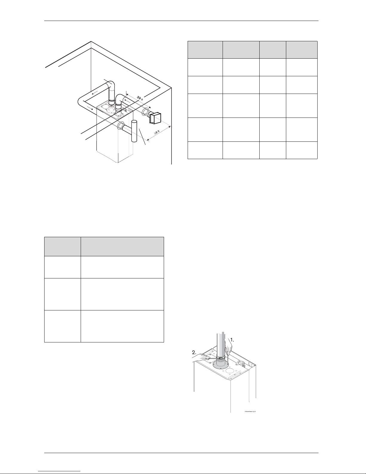
3.6.2 Vent connections and combustion air inlet
restrictors
Exhaust vent connection
B Attach the flue gas exhaust accessory (8 705 504
142) to the top of the unit (position 1) using the 4
screws and gasket provided
B Insert 3" single wall stainless steel vent pipe into
exhaust vent adapter 1.5" and tighten the clamp
(position 2).
Note: Failure to fully insert and tighten vent pipe may
cause flue gas leakage or condensate damage that is
not covered under the manufacturer's warranty.
Fig. 15 Exhaust vent connection
Company Contact information
Z-flex www.z-flex.com
800-654-5600
ProTech
Industries
www.protechinfo.com
800-766-3473
Heat-Fab www.heatfab.com
800-772-0739
Table 4 Vent manufacturer contact information
6720607909-14.3JS
Vent pipe
Combustion
air intake
Z flex Protech Heat Fab
3” Horizontal
terminator
TEE only TEE only 9390 TEE
3” Vertical
terminator
2SVSRCF03 FSRC3 5300CI
90°
Condensate
drain Tee
2SVEVWCF03
FST3 &
FSDF3
93PLSTEE
Horizontal
Condensate
drain
2SVEDWCF03 FSHD03 9321
Condensate
Drain Tube
2SVEDTK N/A 7000TUBE
Table 5 Approved vent termination and condensate
drain part numbers (subject to change)
 Loading...