

Bosch GWH 16 CTD E 31 F5, GWH 12 CTD E 31 F5, GWH 20 CTD E 23 F5, GWH 20 CTD E 31 F5, GWH 12 CTD E 23 F5 L Training And Service Information
...
12 / 16 / 20
12
16 / 20 / 26
INSTANTANEOUS GAS WATER HEATER
GWI-N
FAN PRESSURIZED GAS WATER HEATER FOR
INDOOR AND OUTDOOR INSTALLATION
TRAINING AND SERVICE INFORMATION FOR AFTER SALES
This document is restricted to exclusive use by the official service partners. Each
country should adapt the manual and its contents to the available range.
Page 1 from 76 6 720 814 719 SM FP_Australia 2017/04 EN

Contents
1. INTRODUCTION ........................................................................................... 3
2. APPLIANCE DESCRIPTION ......................................................................... 3
2.1 APPLIANCE DESIGNATION ...................................................................................................... 3
2.2 AVAILABLE ACCESSORIES ..................................................................................................... 4
3. INSTALLATION ............................................................................................. 6
3.1 APPLIANCE FIXATION ON THE WALL ........................................................................................ 6
3.2 WATER CONNECTIONS ........................................................................................................... 7
3.3 GAS CONNECTION ................................................................................................................. 7
3.4 APPLIANCE PERFORMANCE .................................................................................................... 7
4. COMPONENTS OVERVIEW ......................................................................... 8
4.1 CONTROL PANEL................................................................................................................... 9
4.2 HEAT CELL WITH BURNER PIPES ........................................................................................... 12
4.3 GAS MANIFOLD ................................................................................................................... 13
4.4 FAN ................................................................................................................................... 15
4.5 GAS VALVE ........................................................................................................................ 15
4.6 HEAT EXCHANGER .............................................................................................................. 17
4.7 WATER INLET ASSY ............................................................................................................ 18
4.8 WATER TEMPERATURE SENSORS ......................................................................................... 18
4.9 BOX TEMPERATURE SENSOR ............................................................................................... 18
4.10 WATER FLOW SENSOR ..................................................................................................... 23
4.11 IGNITION ELECTRODE ....................................................................................................... 24
4.12 IONIZATION ELECTRODE .................................................................................................... 25
5. WORKING PRINCIPLE / ELECTRIC MEASUREMENTS ............................ 26
6. SERVICE ..................................................................................................... 33
7. MAINTENANCE .......................................................................................... 50
8. TROUBLE SHOOTING ................................................................................ 54
Page 2 from 76 6 720 814 719 SM FP_Australia 2017/04 EN
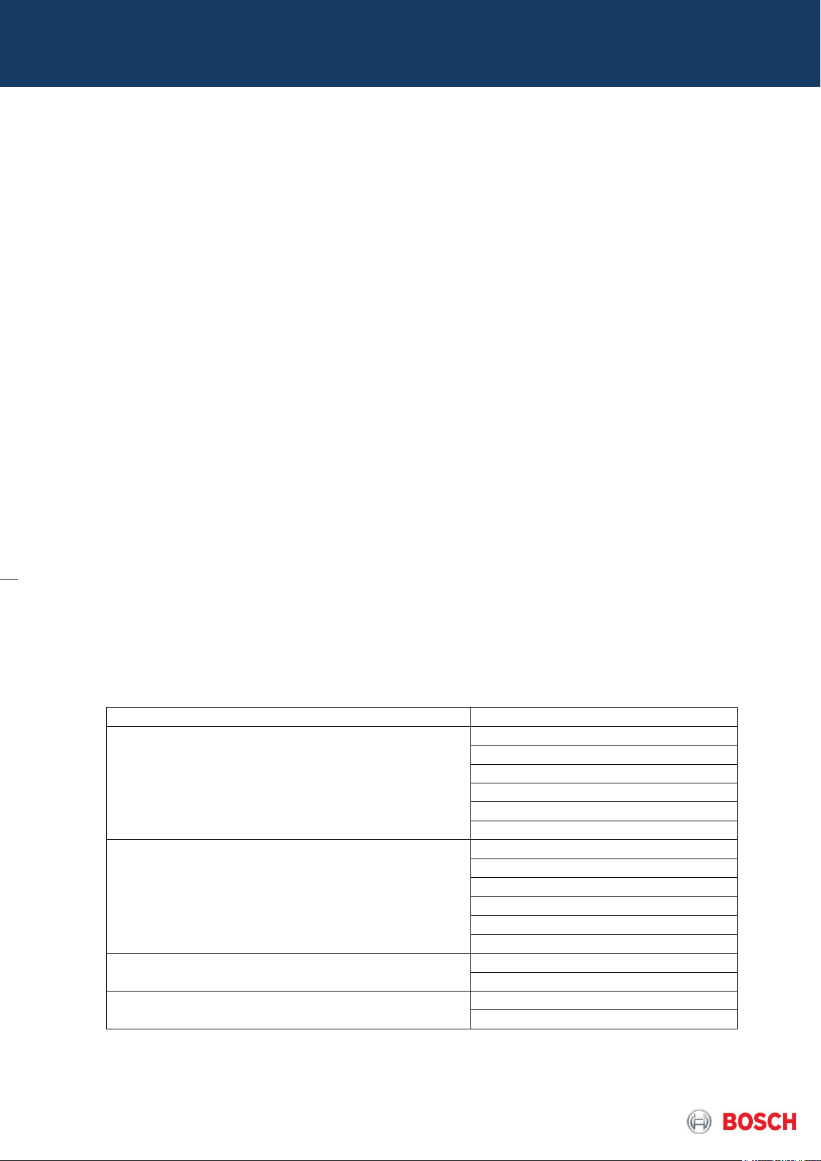
Segment
Designation
Indoor Installation
(temperature setting adjustable degree by degree)
GWH 12 CTD E 23 F5
GWH 12 CTD E 31 F5
GWH 16 CTD E 23 F5
GWH 16 CTD E 31 F5
GWH 20 CTD E 23 F5
GWH 20 CTD E 31 F5
Indoor Installation
(temperature setting locked = L)
GWH 12 CTD E 23 F5 L
GWH 12 CTD E 31 F5 L
GWH 16 CTD E 23 F5 L
GWH 16 CTD E 31 F5 L
GWH 20 CTD E 23 F5 L
GWH 20 CTD E 31 F5 L
Outdoor Installation
(temperature setting adjustable degree by degree)
GWH 12 CTD E 23 F3 O
GWH 12 CTD E 31 F3 O
Outdoor Installation
(temperature setting locked = OL)
GWH 12 CTD E 23 F3 OL
GWH 12 CTD E 31 F3 OL
1. Introduction
This manual is a complement to the instruction/operation manual delivered with the appliance, with the main
important technical details that are relevant for the official service partners and trainers in the country. In any
case one of the documents replaces the use of the other.
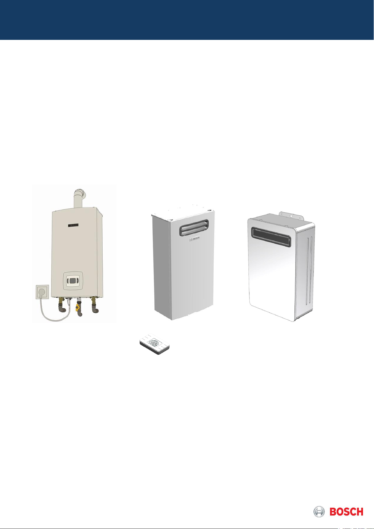
2. Appliance description
This appliance is a fan pressurized gas water heater, which will replace the actual room sealed range of
appliances offering a wider range of modulation and installation advantages with both indoor and outdoor
models available.
2.1 Appliance Designation
The designation allows the identification of the main characteristics of the units, especially when report is needed
through call centre or after sales technicians.
GWH – Instantaneous gas water heater
GWH 12 / 16 / 20 – Output (flow rate at 25ºC rise)
GWH 12 / 16 / 20 CT – Thermostatic control (variable power through electronic control)
GWH 12 / 16 / 20 CTD – Display
GWH 12 / 16 / 20 CTD E – Electronic ignition (source is electricity)
GWH 12 / 16 / 20 CTD E 23/31 – Gas type (23 = natural gas / 31 = liquefied petroleum gas)
GWH 12 / 16 / 20 CTD E 23 /31 F3 O – Flue less model with fan pressurized operation (outdoor unit)
GWH 12 / 16 / 20 CTD E 23 /31 F5 – Room sealed fan pressurized operation (indoor unit)
Table 1 – Appliance identification of low output range (Compact 4000 S)
Page 3 from 76 6 720 814 719 SM FP_Australia 2017/04 EN
Segment
Designation
Outdoor Installation
(temperature setting adjustable degree by degree in
control)
GWH16 3 CT E23 F6 B S2405
GWH16 3 CT E23 F6 S2405
GWH16 3 CT E31 F6 B S2405
GWH16 3 CT E31 F6 S2405
GWH20 3 CT E23 F6 B S2405
GWH20 3 CT E23 F6 S2405
GWH20 3 CT E31 F6 B S2405
GWH20 3 CT E31 F6 S2405
GWH26 3 CT E23 F6 B S2405
GWH26 3 CT E23 F6 S2405
GWH26 3 CT E31 F6 B S2405
GWH26 3 CT E31 F6 S2405
Outdoor Installation
(temperature setting locked = L)
GWH26 3 CT E23 F6 L S2405
GWH26 3 CT E23 F6 LB S2405
GWH26 3 CT E31 F6 L S2405
GWH26 3 CT E31 F6 LB S2405
GWH – Instantaneous gas water heater
GWH 16 / 20 / 26 – Output (flow rate at 25ºC rise)
GWH 16 / 20 / 26 CT – Thermostatic control (variable power through electronic control)
GWH 16 / 20 / 26 CT E – Electronic ignition (source is electricity)
GWH 16 / 20 / 26 CT E 23/31 – Gas type (23 = natural gas / 31 = liquefied petroleum gas)
GWH 16 / 20 / 26 CTD E 23 /31 F6 – Flue less model with fan pressurized operation (outdoor unit)
GWH 16 / 20 / 26 CTD E 23 /31 F6 L – Temperature Locked model
GWH 16 / 20 / 26 CTD E 23 /31 F6 B – Builder Model (Professional segment)
Table 2 – Appliance identification of high output range (Optiflow range)
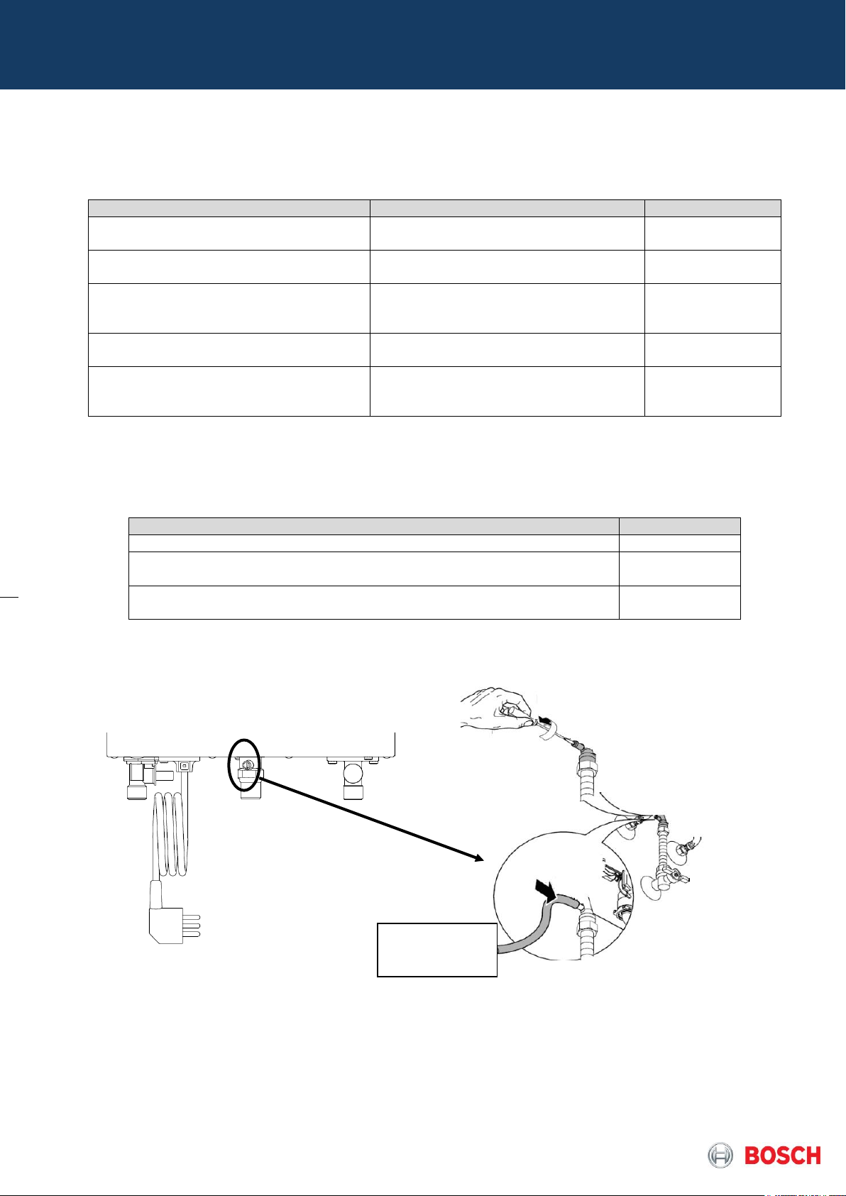
2.2 Available accessories
Remote control
Possible wired connection to both indoor (optional accessory) and outdoor versions (included in packaging)
allowing direct connection to the outside of the appliance with neither the need of configuration, nor a
connection inside of the room sealed box. The GWH 16 / 20 / 26 have internally 3 connections for Remote
control (retail version with inbuilt Bluetooth) and 4 connections for remote control (professional version).
Page 4 from 76 6 720 814 719 SM FP_Australia 2017/04 EN
Pict. 1 – Remote control connection to the appliance (bottom layout in 12/16/20 range)
Activation
Deactivation
T in ≤ 2ºC
T in ≥ 5ºC
or
and
T
box
≤ 5ºC
T
box
≥ 10ºC
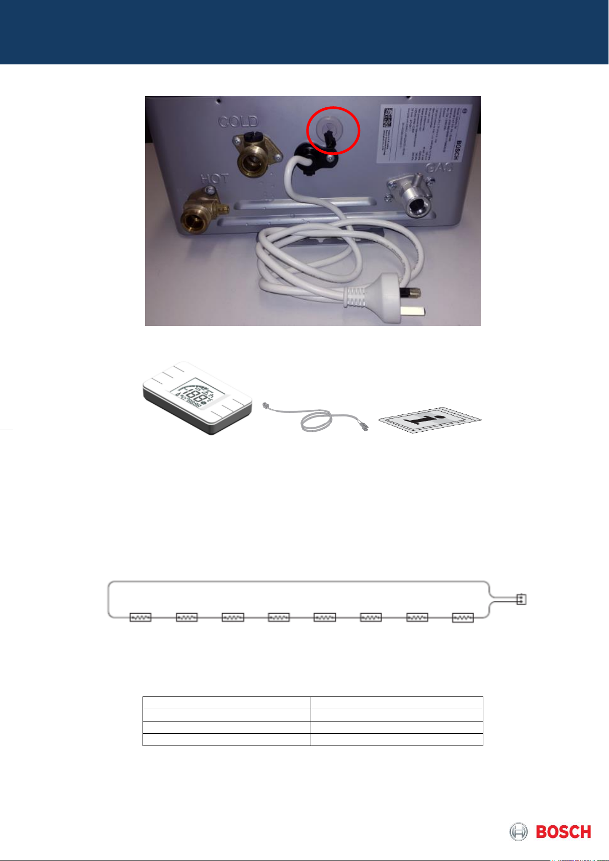
Pict. 2 – Remote control connection to the appliance (bottom layout in outdoor 16/20/26 range)
Pict. 3 – Remote Control with cable, connectors and instruction manual
Anti-Freeze
Allows the protection of the appliance against water freezing inside of its pipes until -20ºC (lower
environment temperature acceptable by gas valve), so to be used in cases where ambient temperature can
be lower than 5ºC. For indoor models is a kit but in outdoor models is inbuilt.
Pict. 4 – Anti-Freeze layout
The kit includes 8 resistances of 16W each, which activate under conditions from table 3.
Table 3 – Anti-freeze activation conditions
Page 5 from 76 6 720 814 719 SM FP_Australia 2017/04 EN
Requisite
Confirmation
Appliance is levelled and in the vertical position?
Delivered accessories are used accordingly?
Appliance is supported exclusively by the wall fixation and not by
hydraulic and/or gas connections?
3. Installation
The installation manual of each product must be checked and used by the installer in order to optimize and
leave the appliance in correct operation conditions.
Check lists for technicians/installers:
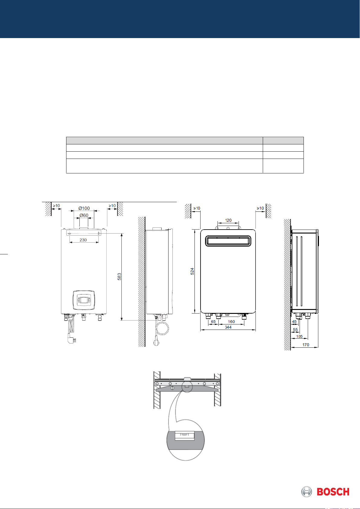
3.1 Appliance fixation on the wall
Table 4 – Check List for Fixation
Pict.5 – Pre-installation distances (indoor / outdoor)
Pict. 6 – Wall Fixation Preparation (if applicable)
Page 6 from 76 6 720 814 719 SM FP_Australia 2017/04 EN
Requisite
Observations
Confirmation
Water pipes were cleaned before
connected to the appliance?
Leakage test was done
successfully?
Inlet water filter was checked and is
cleaned, ensuring the necessary
water flow?
Accessories for water connections
are adequate?
Water pressure and flow are
according to the appliance
specifications?
- Nominal pressure: 300 - 700 kPa
- Minimum pressure: 100 kPa
- Maximum pressure: 1000kPa
Requisite
Confirmation
The appliance is suitable for the available gas type?
Pressure reducer and gas pipe are adequate for the required pressure and
gas flow?
Accessories for gas connection are adequate and according to the country
specification/standards?
Gas
manometer
3.2 Water connections
Table 5 – Check list hydraulic connections
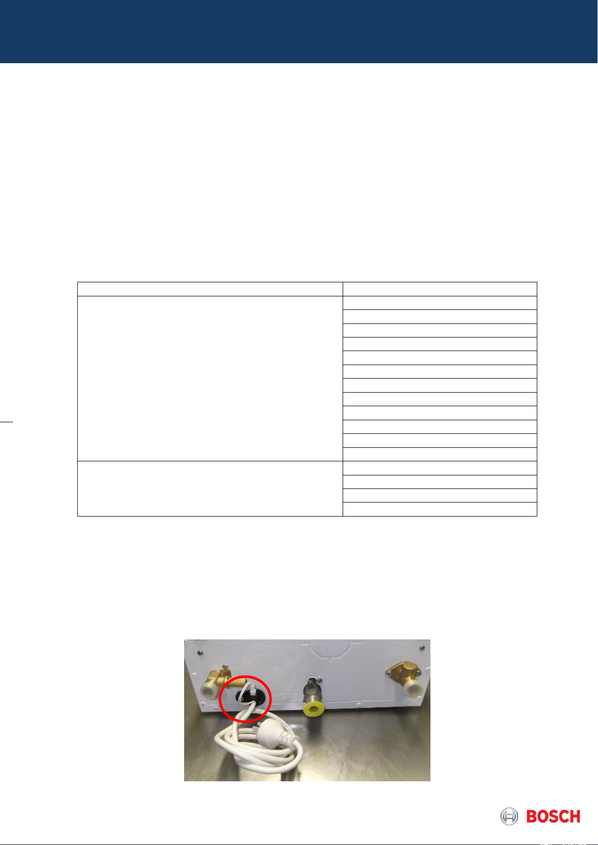
3.3 Gas connection
Table 6 – Check list for gas connections
Pict. 7 – Manometer pipe connection to measure static/dynamic gas supply pressure (showing indoor version)
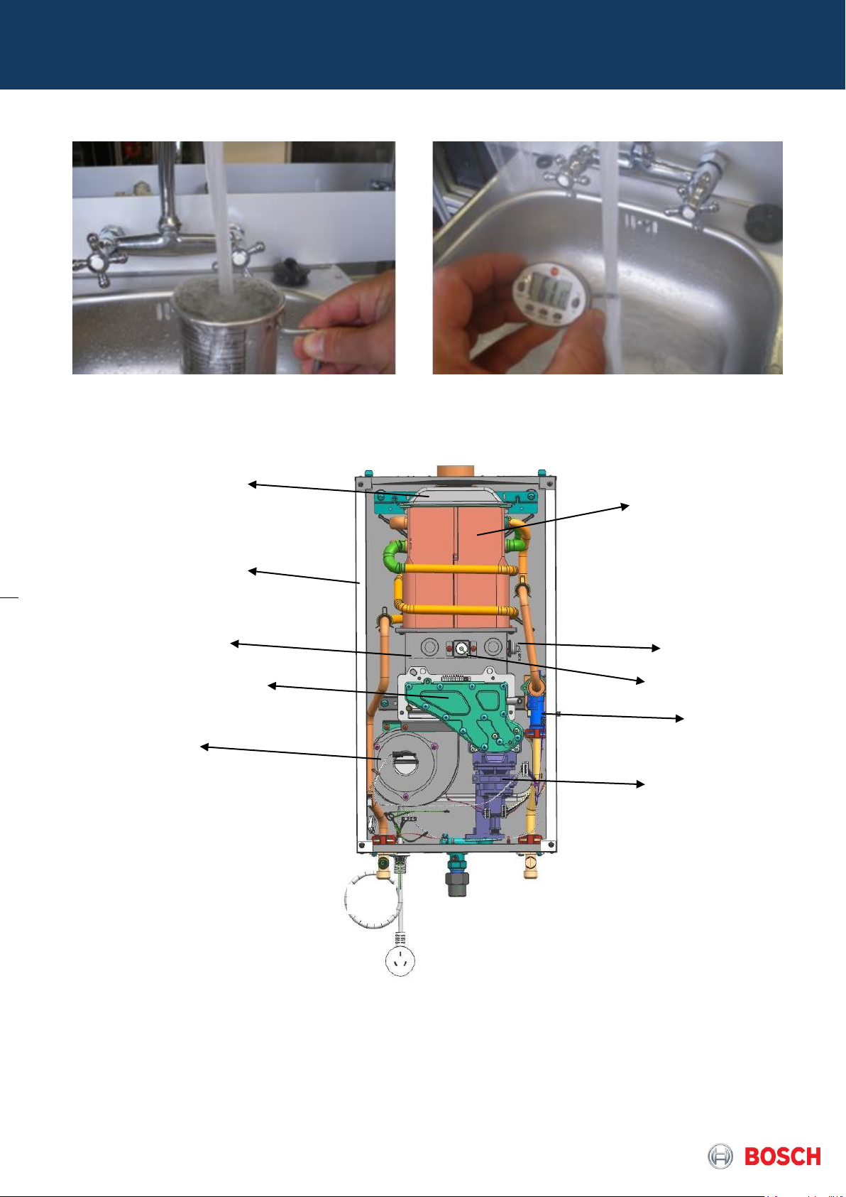
3.4 Appliance performance
Measure water flow and temperature increase to check temperature and instantaneous water flow, assuring
correct operation of the appliance.
Page 7 from 76 6 720 814 719 SM FP_Australia 2017/04 EN
1
3 2 4 6 10 9 8
7
5
11
12
13
4. Components Overview
Pict. 8 – Use of water flow meter and thermometer
1 – Collector
2 – RSF box
3 – Heat exchanger
4 – Heat cell
5 – Burner
6 – Fan
7 – Gas valve
Page 8 from 76 6 720 814 719 SM FP_Australia 2017/04 EN
Pict.9 – Internal view of Indoor models (12 / 16 / 20)
8 – Water valve
9 – Ionization electrode
10 – Ignition electrode
11 – Gas inlet
12 – Water inlet
13 – Water outlet
9
10
11
1 –Collector
2 –Box
3 – Heat exchanger
4 – Burner
5 – Fan
6 – Electronics
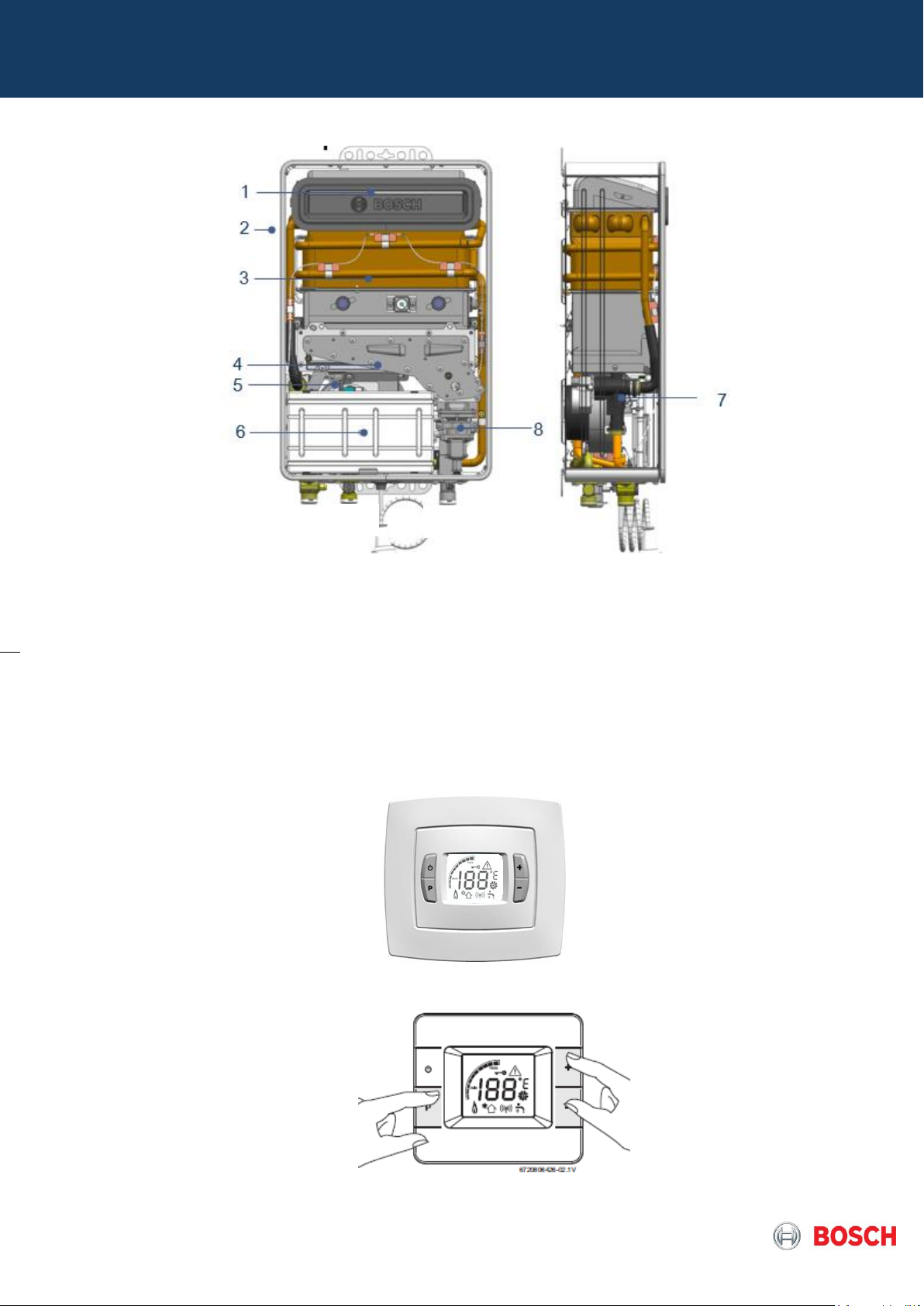
Pict.10 – Internal view of high output outdoor models (16 / 20 / 26)
4.1 Control panel
The control panel allows the user, installer or technician, to perform all different operations needed.
Pict.11 – Control Panel Overview (indoor model)
7 – Flow switch
8 – Gas valve
9 – Gas inlet
10 – Water inlet
11 – Water outlet
Pict.12 – Control Panel Overview in remote
Page 9 from 76 6 720 814 719 SM FP_Australia 2017/04 EN
(optional for indoor model / default for outdoor model)
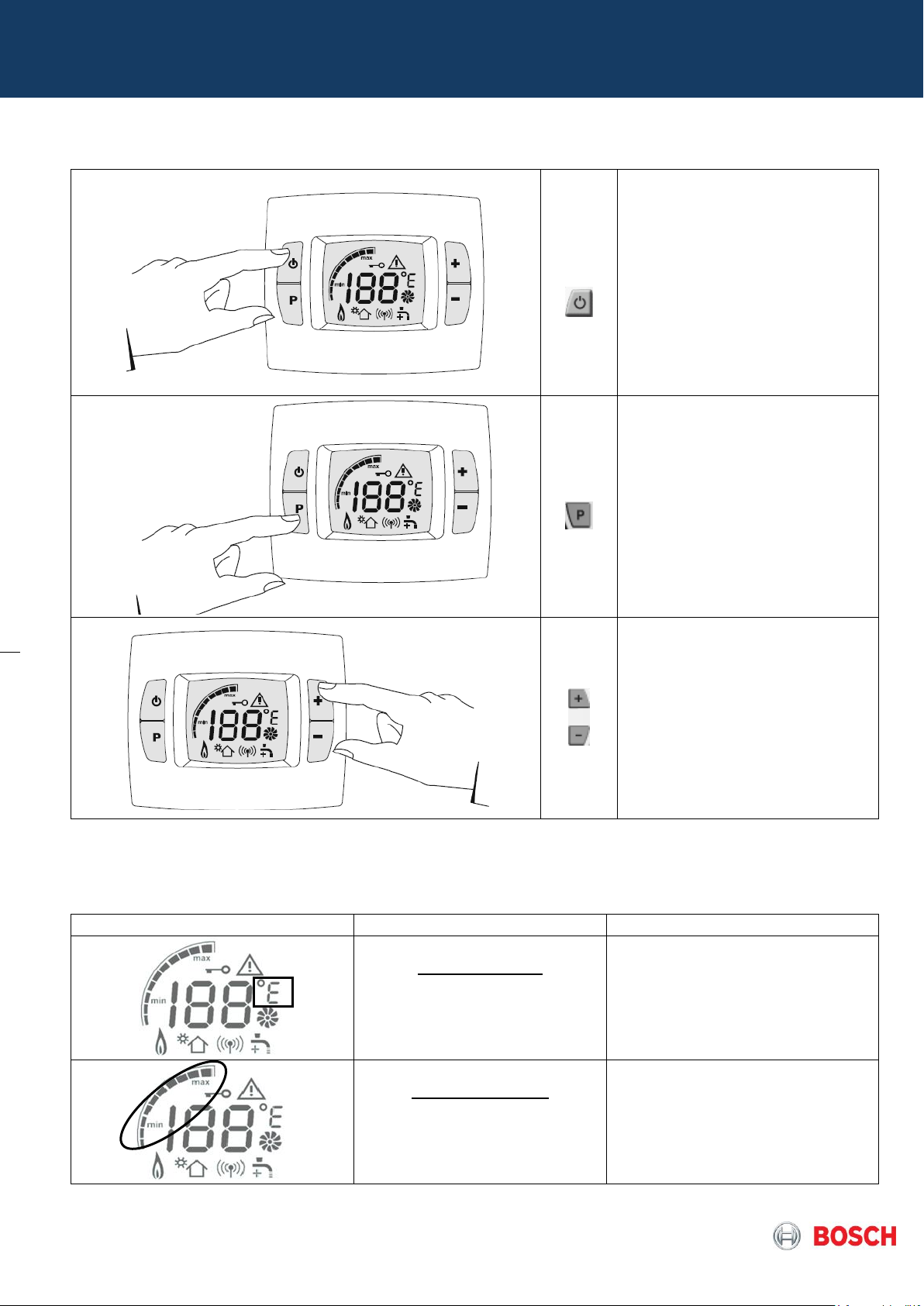
On / Off button
The main switch is assembled on
the PCB and disconnects phase-L
from neutral-N.
No voltage at components if the
main switch is in OFF-position
Note: Errors reset function when
pressed for more than 3 seconds
Program Button
Used to enter in different services:
- Enter in service mode
- Scroll in the service mode menu
- Save value or adjust set values
- Save a temperature set (user)
Selection button
Used to select temperature values,
adjustments and navigation on
parameters inside the visualisation
mode.
Symbol
Description
Observation
Temperature Unit:
ºC – default value
ºF – alternative value
Selection can be done by changing
default value on service mode (P6)
Power bar indicator:
Indication of the current operation
power
Indicative Value (in %)
Page 10 from 76 6 720 814 719 SM FP_Australia 2017/04 EN
Table 7 – Control Panel Buttons
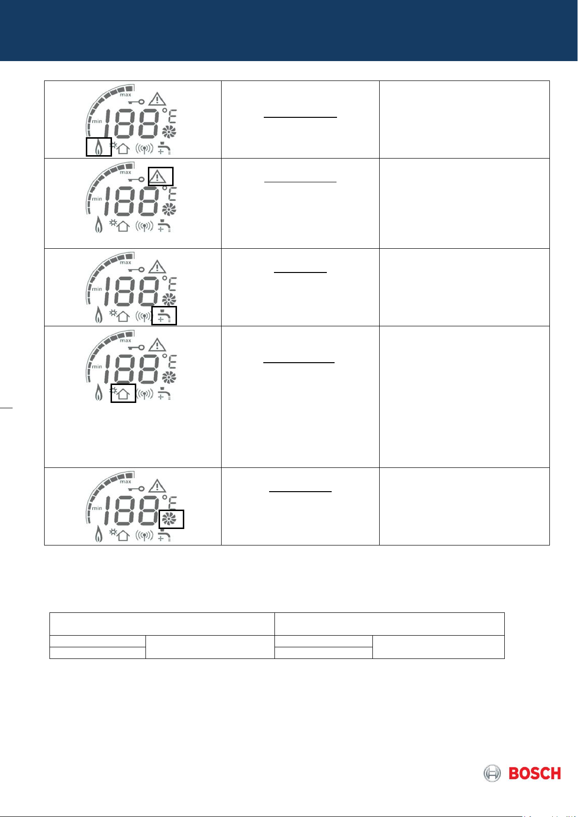
Flame indication:
Indication of flame in the burner
Symbol displayed when ionization is
detected - flame presence
Warning symbol:
Combined with an error indication
/ warning code indicates a faulty
performance
Tap symbol:
Indication of not enough power to
reach set point
In case symbol is displayed,
decrease (-) or increase (+) flow
accordingly
Solar application:
Indication that the automatic solar
function is activated, meaning that
the appliance is receiving pre-
heated inlet water, with no need
for burner to start
The symbol is displayed and burner
is shutdown when T in is under
following conditions:
T in ≥ T
set
– 1K
The symbol is deactivated and
burner restarted when:
T
out
< 60ºC (if T
set
≤ 50ºC)
T
out
< T
set
+ 10ºC (if T
set
> 50ºC)
Fan operation:
Indication that the fan is in
operation
Old TTNR
(with SW WRAF0105)
New TTNR
(with SW WRAF0106)
7-736-503-406
To be used only with
Compact 4000 S
7-736-504-467
Can be used with Compact
4000 S / Optiflow
7-736-502-925
7-736-504-469
There was an update in remote control software version in order to make it compatible for both products in the
market, so please refer to article code of the remote / software version to be used according this recommendation:
The new remote controls are compatible for both Compact 4000S / Optiflow and have new reference and were
implemented from FD >= 660 (Dec. 2016). The old remote controls can be used up until end of stock only with
Compact 4000 S models.
Page 11 from 76 6 720 814 719 SM FP_Australia 2017/04 EN
Table 8 – Display Symbols
Table 9 – Remote Control versions
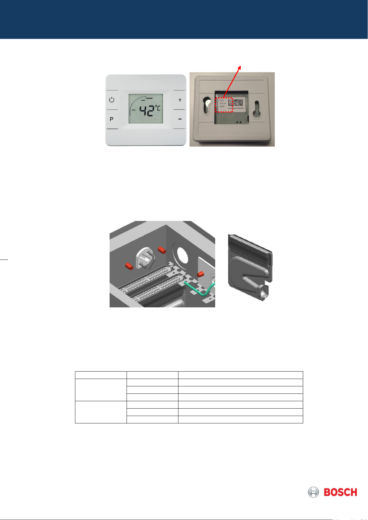
Platform
Appliance
Stamp
Low output (ind
/ out)
12l/min
12 L
16l/min
18 L
20l/min
20 L
High output
(out)
16l/min
code
20l/min
code
26 l/min
code
WRAF0106
Pict 13 – Remote control view and software version sticker location
4.2 Heat cell with burner pipes
The heat cell includes the flame visualization window, ignition electrode, ionization electrode and the burner
pipes.
Inlet: Primary air from the fan and gas from the gas manifold.
Outlet: Hot combustion gases to the heat exchanger
Pict.14 – Heat cell detail with ignition / ionization electrodes and burner blade detail
Primary air plate
The primary air plate is assembled between the heat cell and the gas manifold in order to ensure the correct
mixture of air and gas according to the specific appliance model.
The plate has indexation pins that ensure the correct assembly on the heat cell and the type gas mark
orientation to the front.
Page 12 from 76 6 720 814 719 SM FP_Australia 2017/04 EN
Table 10 – Identification of primary air plates
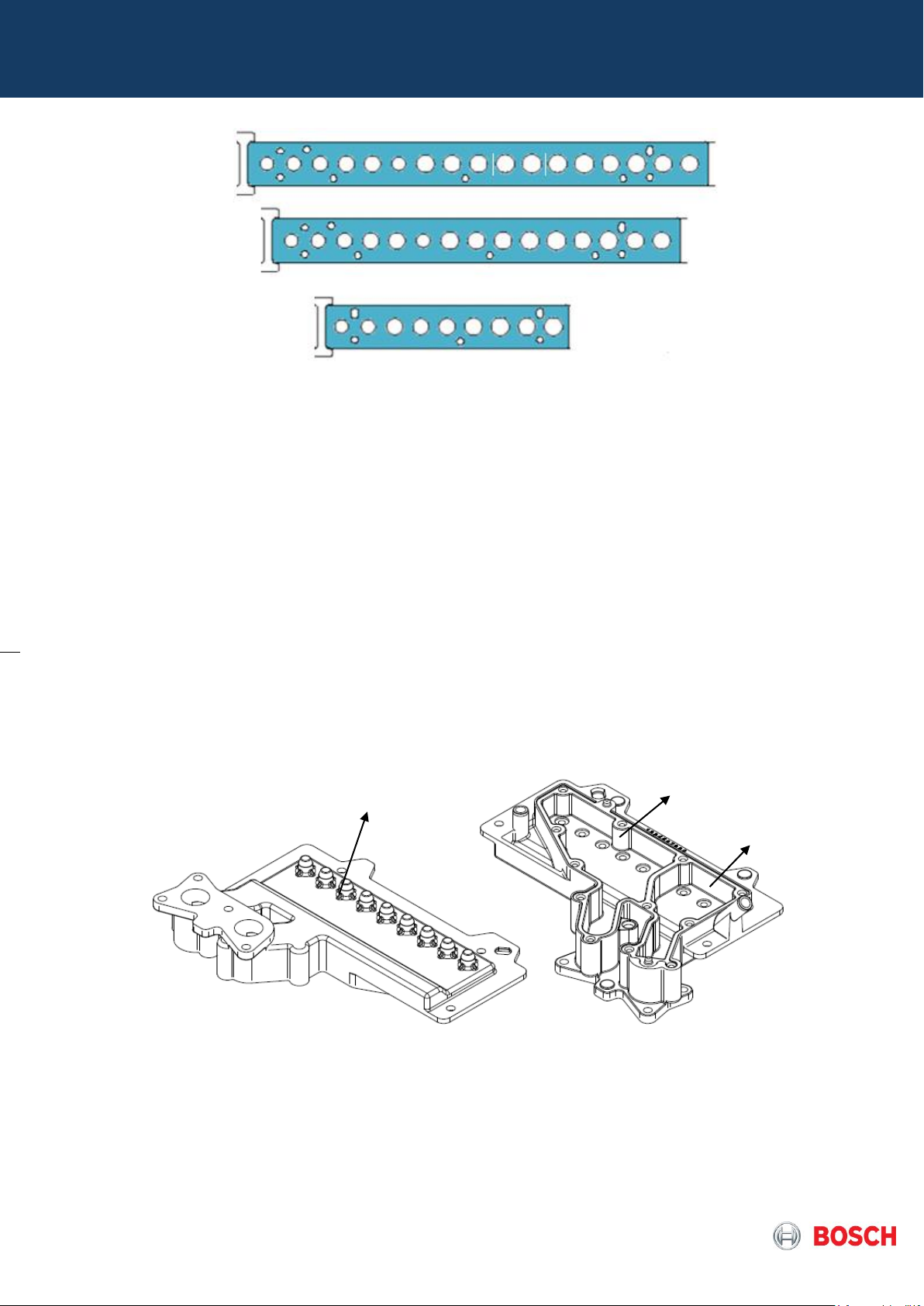
Burner segment 1
Burner segment 2
GWH 12
GWH 16 / 20
Injectors
GWH 26
Pict. 15 – Primary air plate examples
4.3 Gas manifold
The gas manifold is a gas distribution pipe with integrated drilled injectors and two pressure measuring
points:
- gas valve pressure = P
- air fan pressure = P
The manifold cover allows the gas supply to the burner over 2 different segments, in order to assure a wide
modulation range according to the capacity of the appliance.
The gas manifold for GWH 12 models have in total 9 injectors with following distribution:
- NG Ø 1.7
- LPG Ø 1.3
box
burner
The gas manifold for GWH 16 models have in total 15 injectors with following distribution:
Page 13 from 76 6 720 814 719 SM FP_Australia 2017/04 EN
Pict. 16 – Gas manifold for 12l/min (Indoor / Outdoor) appliance with 9 injectors
- NG Ø 1.7
- LPG Ø 1.3 (in 16 l Indoor) or Ø 1.25 (in 16 l Outdoor)
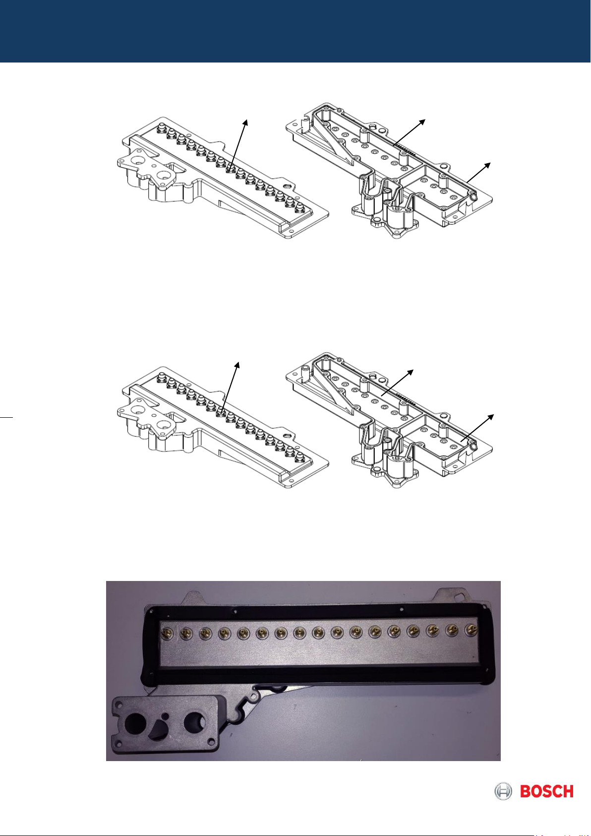
Burner segment 1
Burner segment 2
Burner segment 1
Burner segment 2
Injectors
Injectors
Pict.17 – Gas manifold for 16l/min appliance with 15 injectors
The gas manifold for GWH 20 models have in total 15 injectors with following distribution:
- NG Ø 1.7 in burner segment 1 + Ø 2.0 in burner segment 2
- LPG Ø 1.3 in burner segment 1 + Ø 1.5 in burner segment 2
Pict.18 – Gas manifold for 20l/min appliance with 15 injectors
The gas manifold for GWH 26 models have in total 17 injectors with following distribution:
- NG Ø 2.0 in all burner
- LPG Ø 1.55 in all burner
Page 14 from 76 6 720 814 719 SM FP_Australia 2017/04 EN
Pict.19 – Gas manifold for 26l/min appliance with 17 injectors
Gas Pressure
Measurement point
=
P
burner
Air Pressure
Measurement point
=
P
box
Pict.20 – Pressure measuring points
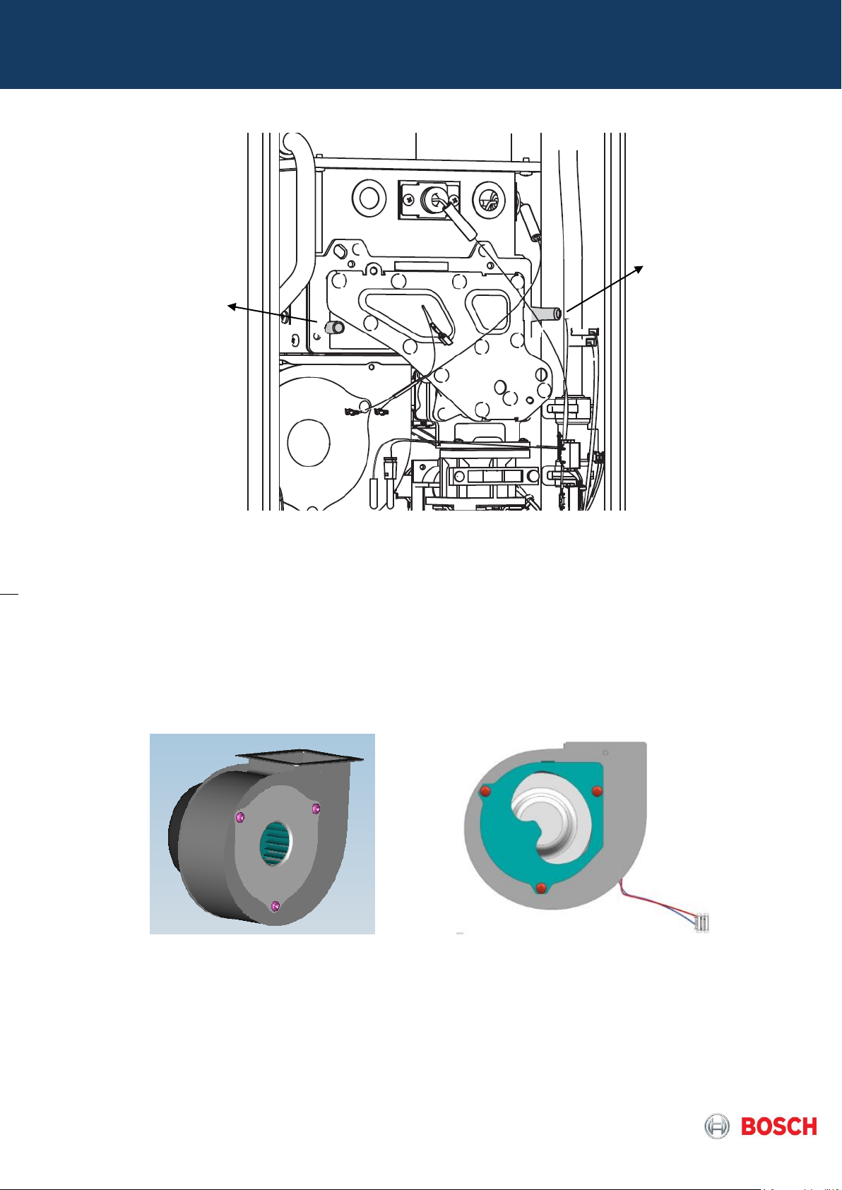
4.4 Fan
The control unit monitories the primary air flow to the burner by varying the fan motor power supply voltage
(DC), ensuring a correct variable speed during the operation according to the output needed.
The fan motor provides an additional control signal to enable/disable operation and the speed of the fan is
measured by the feedback signal provided by the fan’s motor. The signal consists on a square wave with a
frequency proportional to the speed of the fan.
4.5 Gas Valve
Over the control unit it is possible to control the gas flow to the burner by the modulating gas valve (MV1).
The gas valve is composed by other three solenoids identified as safety valves (SV1 + SV2 + SV3) releasing
the modulated gas to and from the solenoid gas valve.
Page 15 from 76 6 720 814 719 SM FP_Australia 2017/04 EN
Pict. 21 – Different fan flanges (12 on left and 16 / 20 / 26 l/min models on right)
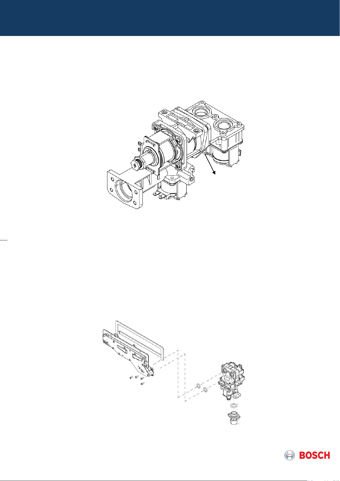
SV1
SV3
SV2
MV1
2nd Burner
Segment
1st Burner
Segment
Safety solenoid valve
The safety valve 1 (SV1) is the first safety element that releases gas to the burner. Safety valves 2 (SV2)
and 3 (SV3) are the second safety level elements, that release gas to the first and second burner segments,
respectively, acting as safety and segmentation valves.
Pict. 22 – Gas Valve
Modulating valve
Mechanical modulated valve
The Gas flow (thermal load) is automatically modulated in order to ensure the correct hot water set
temperature, under water flow or temperature variations.
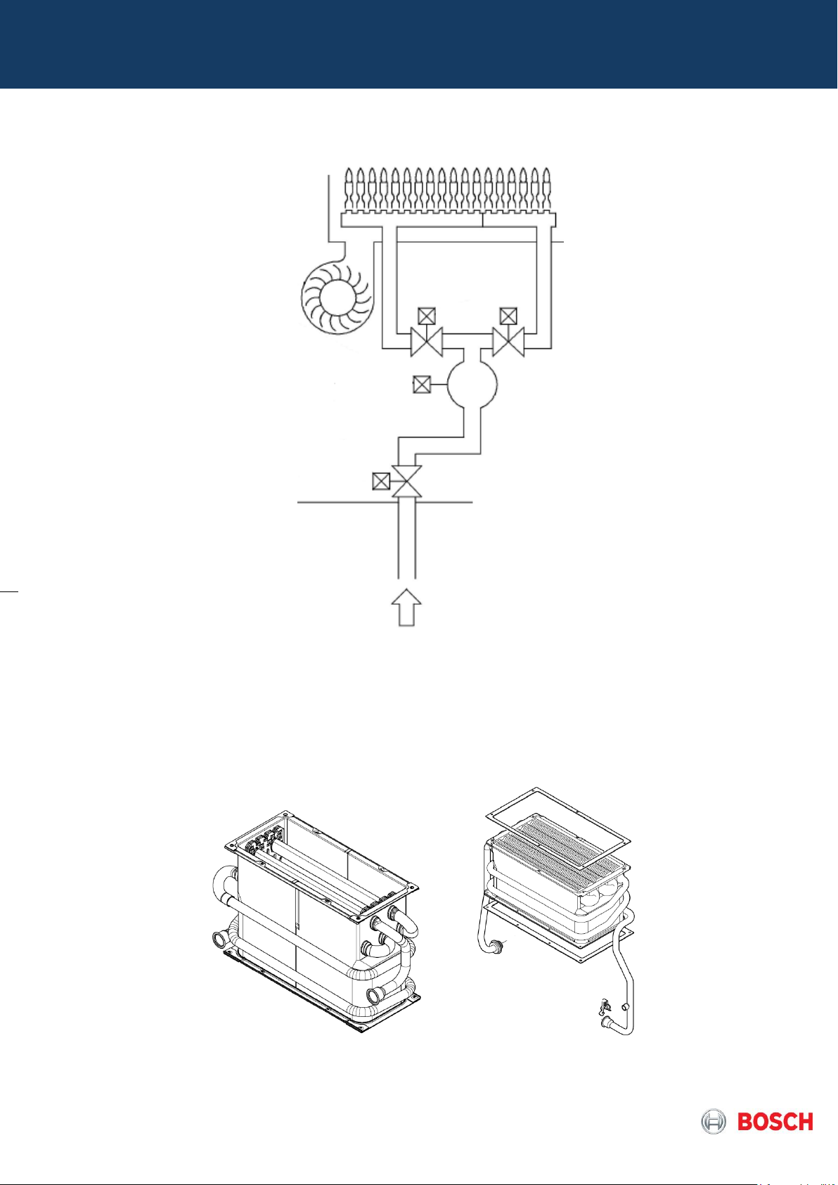
The burner is composed by 2 segments which are fed according to the gas flow for the injectors manifold
released by the solenoid valves activation (SV1 and/or SV2) in gas valve which can be switched over
according to the different thermal load, in order to obtain a stable combustion. These valves ensure the most
suitable condition under the control of microcomputer, based on the values detected by the water flow sensor
and hot water NTC.
Pict. 23 – gas system to burner (gas valve + manifold)
Page 16 from 76 6 720 814 719 SM FP_Australia 2017/04 EN
SV2
SV1
SV3
MV1
Burner
segment 1
Burner
segment 2
Pict.24 – Gas valve / burner scheme
4.6 Heat Exchanger
The copper heat exchanger has different size and number of fins according to the appliance model (12, 16
and 20l/min)and also different copper pipe connections if in high output range (16, 20, 26 l/min). This
configuration ensures the sealed heat transfer from the flame heat to the water that flows through the copper
pipes.
Pict.25 – Heat exchanger
Page 17 from 76 6 720 814 719 SM FP_Australia 2017/04 EN
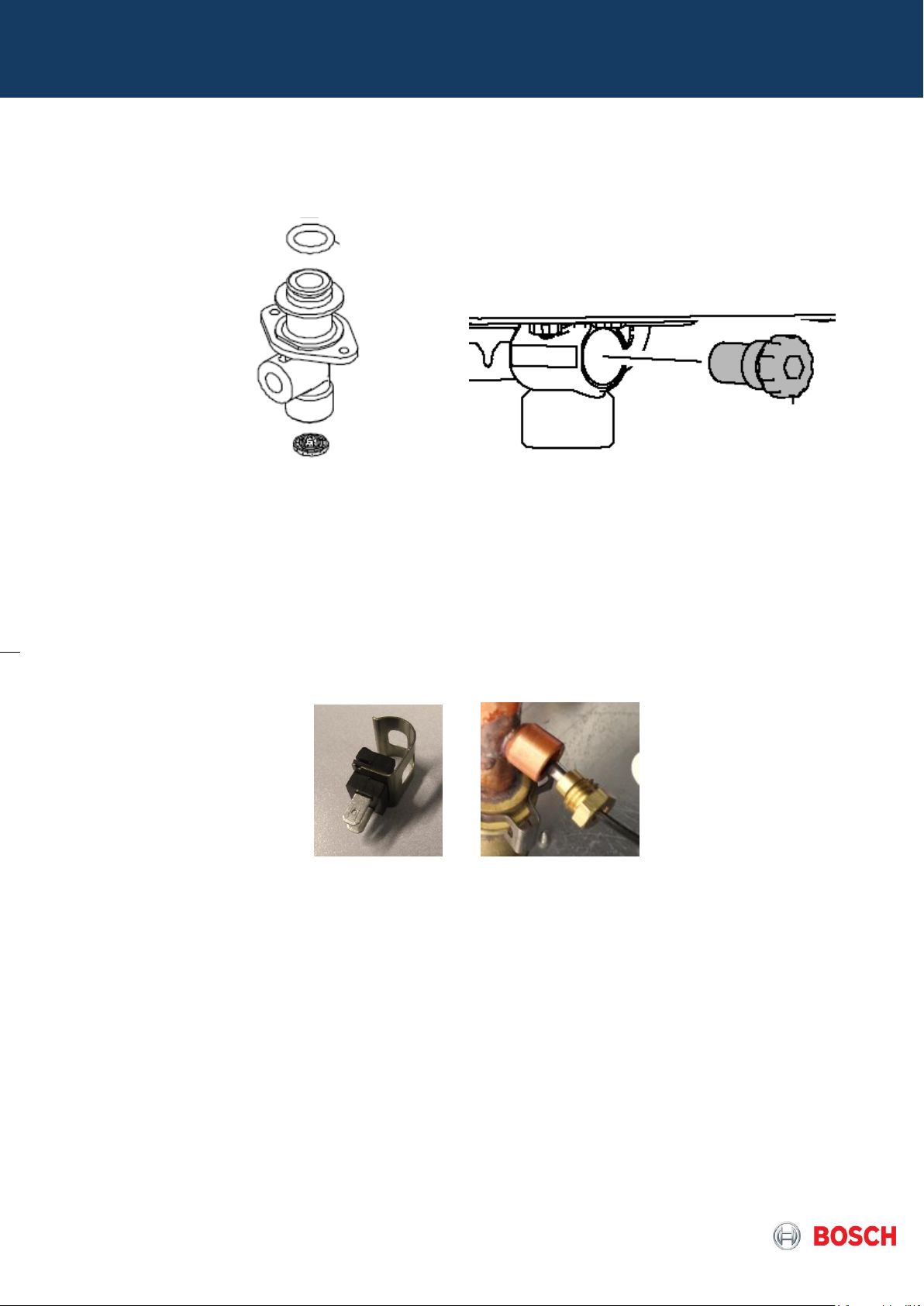
4.7 Water Inlet Assy
The inlet water valve contains the water connection of 1/2” that integrates also the filter mesh or for high
output models is ¾” and contains screw to access filter cartridge.
Pict.26 – Inlet Water Valve for indoor / outdoor
4.8 Water temperature sensors
The outlet and inlet water temperature is measured by a 10kΩ NTC (See table 15). Both NTC are equal, but
connected to different cable colors (blue wires to inlet water / red wires to outlet water). In the high output
range the NTC’s are immerged and as well equal but connected to different cable colors (blue wires to inlet,
red to heat exchanger / orange to outlet).
Contact Type (4000S) Immerged Type (Optiflow)
Pict.27 – NTC Temperature sensor
4.9 Box Temperature sensor
The Box air temperature is measured by a 220kΩ NTC (See table 14) and is assembled on the control unit
back panel, in order to monitor the temperature inside of the room sealed box.
Page 18 from 76 6 720 814 719 SM FP_Australia 2017/04 EN
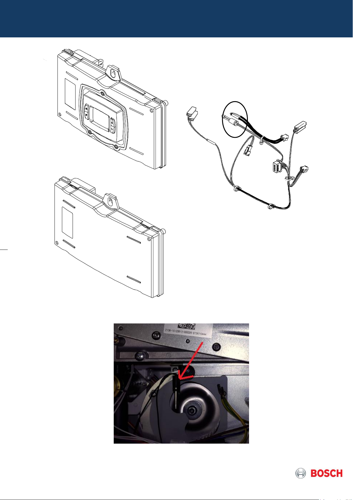
Pict.28 – Box air temperature sensor location in 4000S models
Pict.29 – Box air temperature sensor location in optiflow model
Page 19 from 76 6 720 814 719 SM FP_Australia 2017/04 EN
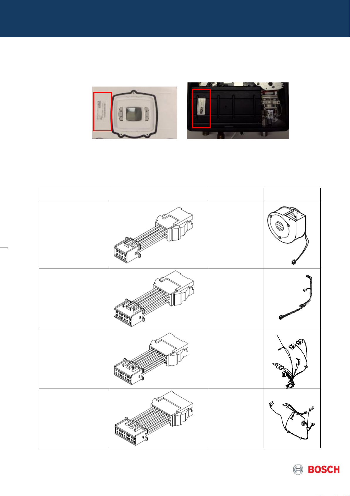
Adaptor name
Adaptor design
Connection
Picture
8 Pins connector
Fan
12 Pins connector
Water Valve
14 Pins connector
Gas valve
16 Pins connector
Sensors
4.10 – PCB (printed circuit board)
The software version is visible in the identification sticker of the control unit as spare part and always refer to
updated versions.
Pict.30 – Identification sticker location according PCB design
The PCB are always compatible with existing cables / interface in the field, nevertheless and for 4000 S models
was done a change in the connector type, so to ensure compatibility between new control unit with cables in the
field, adaptors are be supplied from FD >= 718 (Feb 2017).
Page 20 from 76 6 720 814 719 SM FP_Australia 2017/04 EN
Table 11 – Resume of supplied adaptors
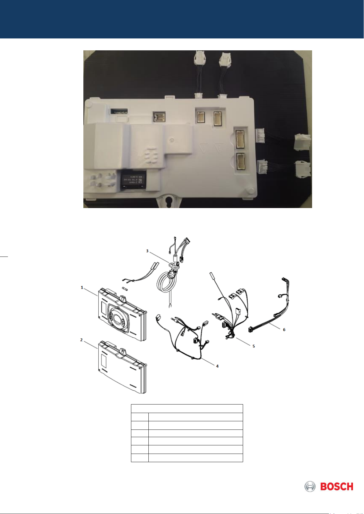
Description
1
Control unit (indoor version)
2
Control unit (outdoor version)
3
Power supply cable
4
Sensor cable
5
Gas valve cable
6
Water valve cable
Pict.31 – Overview of the PCB with adaptors for 4000S
Page 21 from 76 6 720 814 719 SM FP_Australia 2017/04 EN
Picture 32 – Overview of control unit and cables for FP Australia
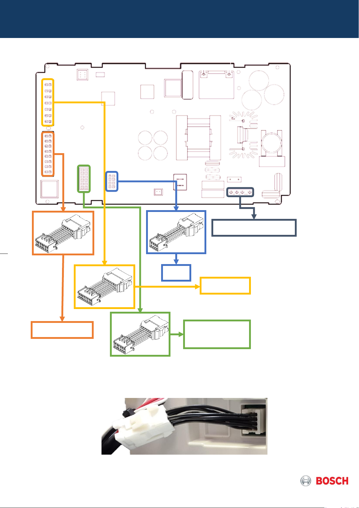
Power supply
Fan
Water valve
Sensors
Gas valve
On the picture 34 is presented the example of an adapter connecting the old cable of the fan with new pcb.
Page 22 from 76 6 720 814 719 SM FP_Australia 2017/04 EN
Picture 33 – Rear view of control unit from FP Australia and adapters use
Picture 34 – PCB with adapter on the Fan terminal
Flow
[l/min]
Frequency
[Hz]
24
96
18
72
14
56
10
40 8 32
4
16
2
8
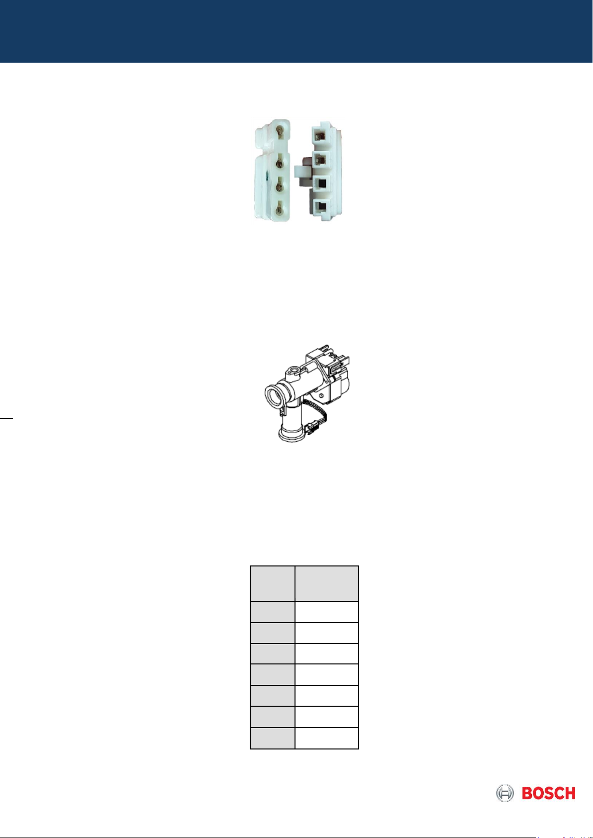
On the Picture 35 is presented the old terminal that is being replaced and the new one in the electrical cable
supply, so this cable will now always be supplied with new PCB.
Picture 35 – Old male terminal (left) and new male terminal (right)
4.11 Water Flow Sensor
Water flow is measured by a turbine flow sensor that is fed by a DC signal, proportional to the measured
water flow.
- Flow rate to operate the appliance: 2 l/min
- Flow rate to shut off the appliance: 1.6 l/min
Pict.36 – Motorized water valve (water flow sensor + stepper motor)
In case Q > 2 l/min following P
verification occurs:
out
- If P
> Minimum Power, the appliance will run with the calculated minimum water flow, in order to
out
reach the set point with a temperature stability of + / - 1ºC;
- If P out < Minimum Power, In case expected T out > set point, burner will shut down.
Table 12 – Water flow sensor values
Page 23 from 76 6 720 814 719 SM FP_Australia 2017/04 EN
 Loading...