

Bosch GWH 260 PN, GWH 1600 P, GWH 1000 P, GWH 425 HN, GWH 425 PN Service Bulletin Booklet
...
Service Bulletin Booklet
For Compact model water heaters
GWH 260 PN, GWH 425 PN, GWH 425 HN
GWH 1000 P, GWH 1600 P, GWH 1600 H
THERMOCOUPLE AND PILOT TEST
MODELS: 1000P, 1600P,
260PN, 425PN
Before replacing the thermocouple, please test the
thermocouple safety circuit and the pilot as follows.
WW
W
WW
LP & NLP & N
G ARE EXTREMELG ARE EXTREMEL
LP & N
G ARE EXTREMEL
LP & NLP & N
G ARE EXTREMELG ARE EXTREMEL
TT
AKE EXTRA PRECAAKE EXTRA PRECA
T
AKE EXTRA PRECA
TT
AKE EXTRA PRECAAKE EXTRA PRECA
PERFPERF
PERF
PERFPERF
ORMINORMIN
ORMIN
ORMINORMIN
G ANY WG ANY W
G ANY W
G ANY WG ANY W
ARNINARNIN
ARNIN
ARNINARNIN
Y FLY FL
Y FL
Y FLY FL
UTIONS WHENUTIONS WHEN
UTIONS WHEN
UTIONS WHENUTIONS WHEN
ORK TORK T
ORK T
ORK TORK T
GG
G
GG
AMMABLE SOAMMABLE SO
AMMABLE SO
AMMABLE SOAMMABLE SO
O THE HEAO THE HEA
O THE HEA
O THE HEAO THE HEA
TERTER
TER
TERTER
CT-02
page 1 of 1
rev 10/06
A. Pilot does not stay lit when the button is
released.
1. When lighting pilot, ensure the gas valve button is fully depressed and held down for at least 15 seconds after pilot is
lit.
2. Pilot flame should be a sharp blue flame that fully engulfs
the thermocouple tip. If pilot does not look this way, please
see bulle tin ‘
on how to clean pilot a ssembly and orifice.
3. If heater is equipped with an AQ4 power vent kit (models
1600P and 425PN only), press reset button on power vent
spill switch to check if it is tripped. NOTE: r unning the heater
without electrical power to power vent fan will trip the spill
switch. Also check the AQ4 safety circuit connections for
corrosion or loose connections. Consult AQ4 manual for part
locations.
4. Check the electromagnet connections. The electromagnet
is located on the back side of the gas valve. The electromagnet connection from the thermocouple is a 5 mm brass nut
that screws into a 17 mm aluminum nut. Tighten both nuts
snugly but do not over tighten.
5. Check if connections at both temperature limiters (ECO) are
loose or corroded. Clean any corrosion with very fine sand
paper or an eraser and reconnect leads.
6. If cleaning the terminals attached to the ECO’s does not fix
the problem, choose one ECO and remove two wires attached. Connect a jumper wire between the two wires removed from the ECO. Try to relight the pilot. If the pilot
flame now remains on, the ECO may be defective. If the
pilot still goes out, remove jumper, reconnect wires leads
and perform the same step with the other ECO.
7. Replace ECO.
8. Have a licensed gas technician verify the proper operation of
the thermocouple. To test the thermocouple, disconnect wire
from the thermocouple where it connects to the upper ECO
(located top right side of the heat exchanger). Insert a multimeter probe into the thermocouple lead and attach or hold
the other probe to the metal chassis of the heater (DC common). Light the pilot flame and hold button while observing
the meter reading. If the reading is 24mVDC or more the
thermocouple is good.
CT-22 Cleaning pilot assembly’ for instructions
Note: Never attempt to operate heater for normal
use with jumper wire connected!
B. Pilot goes out during use
1. Light the pilot and allow it to warm the thermocouple tip for
2 minutes.
2. Perform dr op test by blowing out the pilot flame and listen
for the electromagnet to close. This closure will make a distinct clunk noise as it shuts. The time between blowing out
the flame and the electromagnet closing should be between
20 and 30 seconds. Units equipped with an AQ4 power vent
kit have drop times between 10 and 15 seconds.
3. Repeat drop test several times to confirm it is consistent
4. If drop times are not within specifications, then follow steps
2-7 in section A. After each step, repeat drop test. Proceed
to the next step until drop test is within specifications.
C. Pilot goes out during use and drop test is
within specifications.
1. Check the vent size and length. Vent should be 5 inches in
diame ter for the 1600P and 425PN and 4 inches in diameter
for the 1000P and 260PN. The heater mus t have a rise of 1foot before any elbo ws in the vent system, at least 6 feet
vertical in length and terminate through the roof. Any reduction in vent size or the presence of an elbow directly on the
top of the unit may cause the flue gas sensor to trip the pilot
safety circuit. Please see t he venting section in the manual
for more de tailed information regarding the required venting
for this heater.
2. Inspect the draft hood and heat exchanger fins for signs of
soot build-up or any other foreign material such as spider
webs. Clean out any debris found in the vent hood. Signs of
soot indicate insufficient combustion air or exhaust draft.
Check for vent assembly blockage or combustion air blockage on the underside of the unit. Ensure combustion air
requirements are being met as specif ied in the installation
manual.
3. Measure the outgoing temperature of the hot water exiting
the unit. Temperature in excess of 160F may trip the pilot
safety circuit. The heater must not be supplied with w ater in
excess of 90F. Preheated water may cause the heater to
overheat the outlet water and shut down as a safety precaution.
©BBT NORTH AMERICA CORPORATION
Bosch Group
Bosch Water Heating
340 Mad River Park, Waitsfield, VT 05673
CHECKING THE DRAFT
MODELS: 1000P, 1600P, 1600H
260PN, 425PN, 425HN
1. Close all doors and window in the building.
2. Operate all fuel burning appliances and exhaust
systems in the building with the exception of the
tankless water heater. Allow time for these items to
utilize the air in the structure. Up to one hour may
be necessary.
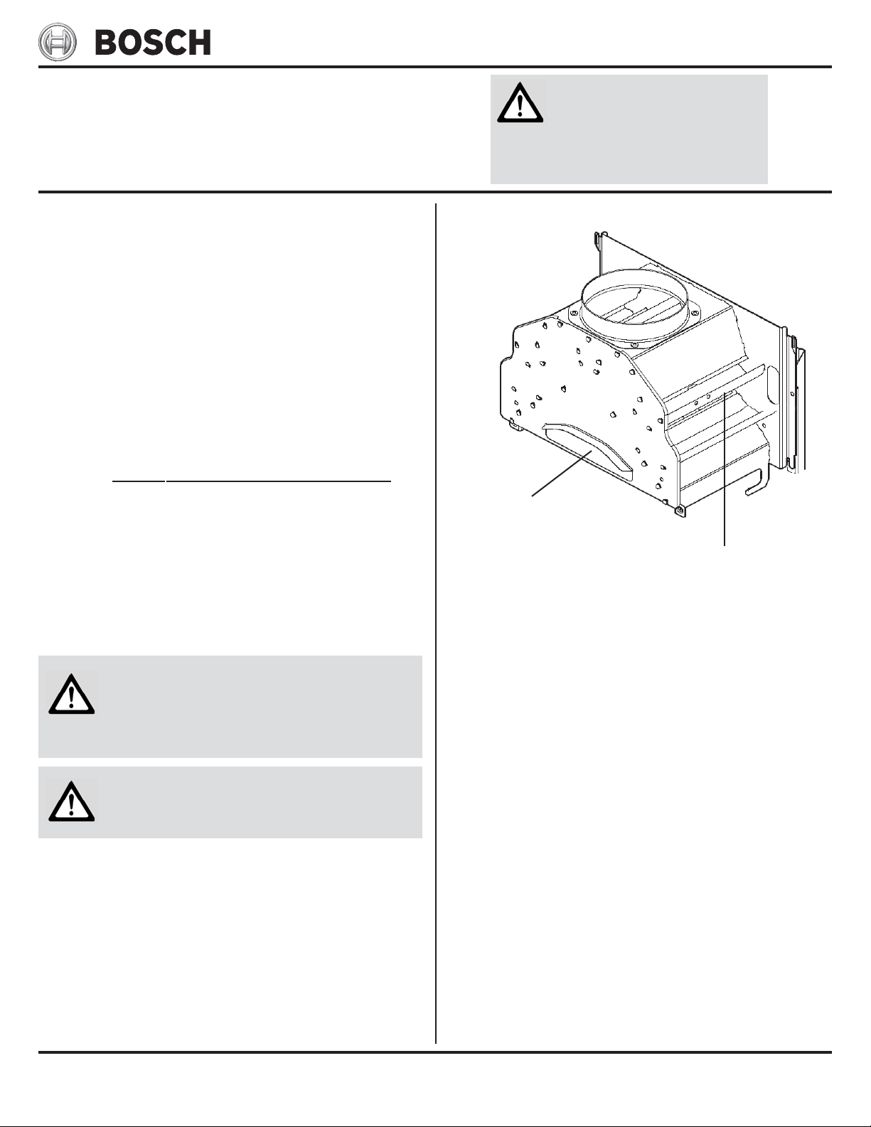
3. Remove the cover from the tankless unit and hold a
recently extinguished match, candle, or any other
visible smoke source in front of the triangular opening on the draft diverter.
4. The smoke should be sucked quickly into the opening
and up the exhaust vent. If the smoke is blown back,
a negative air situation exists and must be corrected.
See the combustion air section in the manual or
bulletin CT-05 Negative air and freeze prevention.
5. Now run the heater for 10 minutes, then hold a
smoke source at the top right side of the draft
diverter. The smoke should be drawn in the louvers
on the side. If this is not the case, the unit is not
drafting properly and flue gases are being exhausted
into the space in which the heater is installed. This
is not safe and must be corrected. Reference the
venting section in the manual to ensure venting is in
accordance with the manufacturer’s specifications.
WW
ARNINARNIN
W
ARNIN
WW
ARNINARNIN
LP & NLP & N
G ARE EXTREMELG ARE EXTREMEL
LP & N
G ARE EXTREMEL
LP & NLP & N
G ARE EXTREMELG ARE EXTREMEL
TT
AKE EXTRA PRECAAKE EXTRA PRECA
T
AKE EXTRA PRECA
TT
AKE EXTRA PRECAAKE EXTRA PRECA
PERFPERF
ORMINORMIN
PERF
ORMIN
PERFPERF
ORMINORMIN
Step 3: Hold extiguished
match here
G ANY WG ANY W
G ANY W
G ANY WG ANY W
1000P. 1600P, 1600H,
260PN, 425PN, 425HN
GG
G
GG
Y FLY FL
AMMABLE SOAMMABLE SO
Y FL
AMMABLE SO
Y FLY FL
AMMABLE SOAMMABLE SO
UTIONS WHENUTIONS WHEN
UTIONS WHEN
UTIONS WHENUTIONS WHEN
ORK TORK T
O THE HEAO THE HEA
ORK T
O THE HEA
ORK TORK T
O THE HEAO THE HEA
Step 5: Hold extiguished
match here
TERTER
TER
TERTER
CT-03
page 1 of 1
rev 09/06
Note: Poor venting can result in excessive sooting around the water heater,
overheating, and release dangerous
carbon monoxide into the living space
causing serious injury and/or death.
Note: Damage to the heater as a result
of improper venting will not be covered
under warranty.
©BBT NORTH AMERICA CORPORATION
Bosch Group
Bosch Water Heating
340 Mad River Park, Waitsfield, VT 05673
CHECKING GAS PRESSURE
MODELS: 1000P, 1600P, 1600H
260PN, 425PN, 425HN
WW
W
WW
LP & NLP & N
G ARE EXTREMELG ARE EXTREMEL
LP & N
G ARE EXTREMEL
LP & NLP & N
G ARE EXTREMELG ARE EXTREMEL
TT
AKE EXTRA PRECAAKE EXTRA PRECA
T
AKE EXTRA PRECA
TT
AKE EXTRA PRECAAKE EXTRA PRECA
PERFPERF
PERF
PERFPERF
ORMINORMIN
ORMIN
ORMINORMIN
G ANY WG ANY W
G ANY W
G ANY WG ANY W
ARNINARNIN
ARNIN
ARNINARNIN
Y FLY FL
Y FL
Y FLY FL
UTIONS WHENUTIONS WHEN
UTIONS WHEN
UTIONS WHENUTIONS WHEN
ORK TORK T
ORK T
ORK TORK T
GG
G
GG
AMMABLE SOAMMABLE SO
AMMABLE SO
AMMABLE SOAMMABLE SO
O THE HEAO THE HEA
O THE HEA
O THE HEAO THE HEA
TERTER
TER
TERTER
CT-04
page 1 of 1
rev 10/06
A. Connecting manometer:
1. Turn off gas using installer supplied manual shutoff.
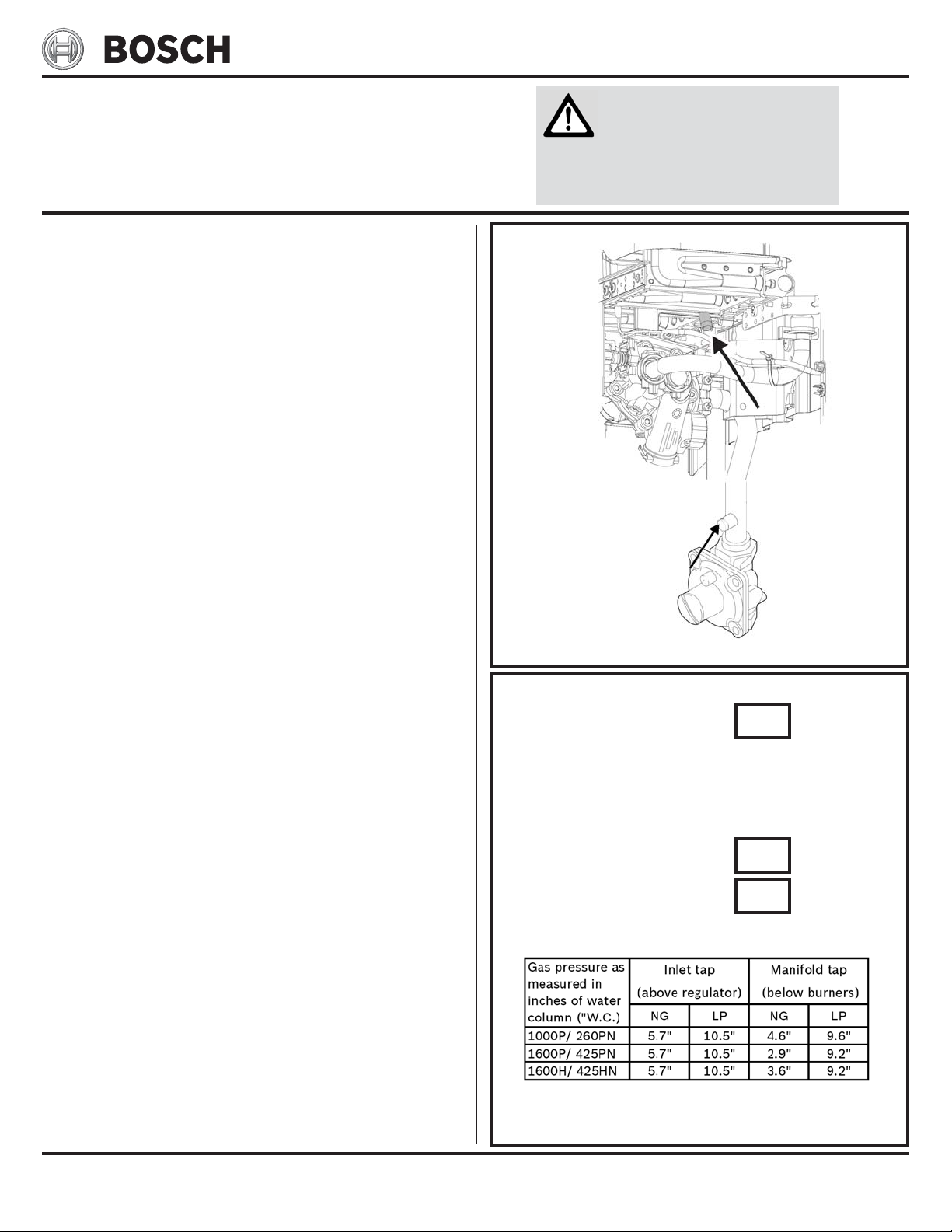
2. Remove front cover (see manual for instructions) and lo-
cate inlet gas pressure tap above the regulator on the gas
inlet pipe and the manifold gas pressure tap on the right
side directly below the burner (Fig. 1).
3. Select appropriate pressure tap per specific pressure test
(see steps B and C). Loosen the screw from test point fitting (do not remove) and connect manometer tube on test
point.
B. Static pressure test (Inlet pressure tap
only)
1. Turn gas supply back on.
2. Operate all other gas appliances at maximum output.
3. Record static pressure reading in Table 1.
4. Leave manometer connected to inlet tap for oper ating pres-
sure test.
C. Operating pressure test
1. Light pilot if neccessary (1000P, 1600P, 260PN and 425PN
models).
2. All other gas appliances should still be running at full ca-
pacity.
3. Set heater to maximum output:
1000P, 1600P, 260PN, 425PN:
Set gas slide control to the right. Turn temperature
adjustment knob full clockwise.
1600H, 425HN:
Turn power adjustment knob full clockwise. Turn
temperature adjustment knob full clockwise.
4. Open all hot water taps supplied by this unit.
5. Record inlet tap oper ating pressure reading in Table 1.
6. Tur n off gas supply as well as all hot water taps. Disconnect
manometer from the inlet tap. Tighten screw in tap fitting
or gas leak may occur.
7. Reconnect manometer to the manifold gas pressure tap.
8. Turn gas supply back on and follow steps 1 through 4.
9. Record manifold tap operating pressure reading in Table 1.
10. Turn off gas supply as well as all hot water taps. Disconnect
manometer from the manifold tap. Tighten screw in tap fitting or gas leak may occur.
11. Put cover back on water heater, open gas supply and re turn
heater to service.
FIGURE 1
Mainfold tap
Inlet tap
GAS PRESSURE TEST POINTS
TABLE 1
Static gas pressure: “ W.C.
Required static gas pressure (all models:
NG 7” - 14” W.C.
LPG 11” - 14” W.C.
Operating gas pressure:
Inlet Tap “ W.C.
Manifold tap “ W.C.
Minimum require operating gas pressure:
©BBT NORTH AMERICA CORPORATION
Bosch Group
Bosch Water Heating
340 Mad River Park, Waitsfield, VT 05673
NEGATIVE AIR & FREEZE
PREVENTION
MODELS: 1000P, 1600P, 1600H,
260PN, 425PN, 425HN
WW
W
WW
LP & NLP & N
G ARE EXTREMELG ARE EXTREMEL
LP & N
G ARE EXTREMEL
LP & NLP & N
G ARE EXTREMELG ARE EXTREMEL
TT
AKE EXTRA PRECAAKE EXTRA PRECA
T
AKE EXTRA PRECA
TT
AKE EXTRA PRECAAKE EXTRA PRECA
PERFPERF
PERF
PERFPERF
ORMINORMIN
ORMIN
ORMINORMIN
G ANY WG ANY W
G ANY W
G ANY WG ANY W
ARNINARNIN
ARNIN
ARNINARNIN
Y FLY FL
Y FL
Y FLY FL
UTIONS WHENUTIONS WHEN
UTIONS WHEN
UTIONS WHENUTIONS WHEN
ORK TORK T
ORK T
ORK TORK T
GG
G
GG
AMMABLE SOAMMABLE SO
AMMABLE SO
AMMABLE SOAMMABLE SO
O THE HEAO THE HEA
O THE HEA
O THE HEAO THE HEA
TERTER
TER
TERTER
CT-05
page 1 of 1
rev 10/06
Negative Air
• Negative air pressure in a str ucture occurs when air consumed by fuel burning appliances or exhaust systems in that
structure exceeds the amount of air available.
• Here is a list of items that consume air within a typical household:
• Stove exhaust fans
• Furnaces
• Water heaters
• Fireplaces/ Woodstoves
• Bath fans
• Dryers
• All of these items must be taken into account when making
provisions for a proper amount of fresh air from the outside.
• If the building is new construction, air infiltration from the
outside will be limited and provisions for extra air supply
should be made. If the building is older construction, air may
infiltr ate into the house through unplanned sources such as
window frames, door jams, sill plates or idle chimney flues.
These sources still may not be providing the adequate amount
of air and additional sources of fresh air should be considered.
Why Negative Air is Bad
Cold air from the outside is drawn through the water heater’s
flue pipe because other fuel burning appliances or exhaust
systems in the str ucture require more air than the dwelling
can supply. When the required amount of air for the fuel
burning appliances or exhaust systems in t he structure is
not being supplied to them, they find the flue pipe on the
water heater an acceptable means of supplying themselves.
Thus, freezing cold air is pulled down the water heater’s flue,
drawn over the copper heat exchanger, potentially freezing
it and the water valve below. Because, when idle, the water
heater holds only cold water, fr eezing can happen quickly
possibly causing leaks or ruptures in the heat exchanger and/
or the water valve. The water heater does not pull air through
its flue pipe – if you w ere to remove the heater, the air would
continue to come down your flue pipe. You must ha ve the air
balanced in the structure to correct this pr oblem. Consultation with a heating, ventilating and air conditioning (HVAC)
specialist is recommended.
Note: Poor venting can result in excessive
sooting around the water heater, overheating, and release dangerous carbon monoxide into the living space causing serious injury and/or death.
Note: Damage to the heater as a result of
improper venting will not be covered under warranty.
Checking for Negative Air
1. Close all doors and windows in the building.
2. Operate all fuel burning appliances and exhaust systems in
the building at full capacity with the exception of the tankless
water heater. Allow time for these items to utilize the air in
the structure. Up to one hour may be necessary.
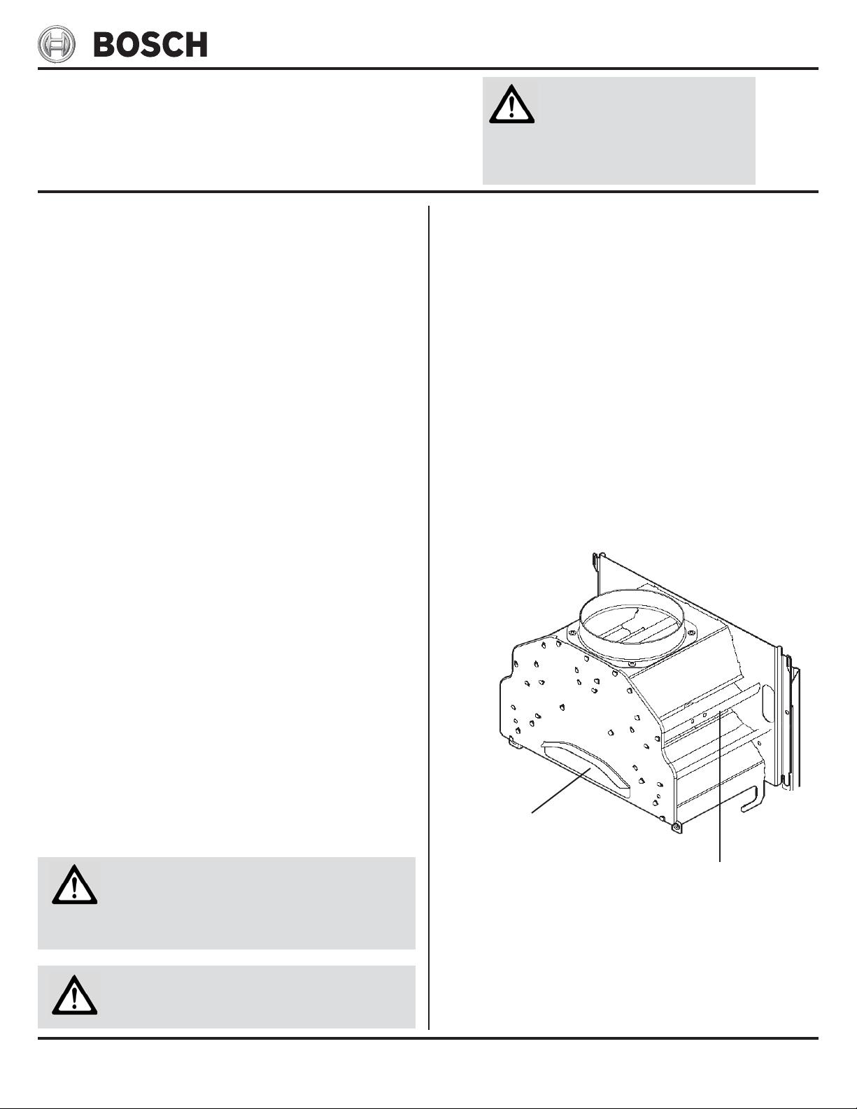
3. Remove the cover from the tankless unit and hold a recently
extinguished match, candle, or any other visible smoke source
in front of the triangular opening on the draft diverter.
4. The smoke should be sucked quickly into the opening and up
the exhaust vent. If the smoke is blown back, a negative air
situation exists and must be corrected. See the combustion
air section in the manual for specifications.
5. Now run the heater for 10 minutes, then hold a smoke source
at the top right side of the draft diverter. The smoke should
be drawn in the louvers on the side. If this is not the ca se,
the unit is not drafting properly and flue gases are being
exhausted into the space in which the heater is ins talled.
This is not safe and must be corrected. Reference the venting section in the manual to ensure venting is in accordance
with the manufacturer’s specifications.
Step 3: Hold extiguished
match here
Step 5: Hold extiguished
match here
DRAFT DIVERTER FOR:
1000P, 1600P, 1600H,
260PN, 425PN, 425HN
©BBT NORTH AMERICA CORPORATION
Bosch Group
Bosch Water Heating
340 Mad River Park, Waitsfield, VT 05673

OVERCOMING FLUCTUATING
TEMPERATURES
MODELS: 1000P, 1600P, 1600H
260PN, 425PN, 425HN
WW
W
WW
LP & NLP & N
G ARE EXTREMELG ARE EXTREMEL
LP & N
G ARE EXTREMEL
LP & NLP & N
G ARE EXTREMELG ARE EXTREMEL
TT
AKE EXTRA PRECAAKE EXTRA PRECA
T
AKE EXTRA PRECA
TT
AKE EXTRA PRECAAKE EXTRA PRECA
PERFPERF
PERF
PERFPERF
ORMINORMIN
ORMIN
ORMINORMIN
G ANY WG ANY W
G ANY W
G ANY WG ANY W
ARNINARNIN
ARNIN
ARNINARNIN
Y FLY FL
Y FL
Y FLY FL
UTIONS WHENUTIONS WHEN
UTIONS WHEN
UTIONS WHENUTIONS WHEN
ORK TORK T
ORK T
ORK TORK T
GG
G
GG
AMMABLE SOAMMABLE SO
AMMABLE SO
AMMABLE SOAMMABLE SO
O THE HEAO THE HEA
O THE HEA
O THE HEAO THE HEA
TERTER
TER
TERTER
CT-06
page 1 of 1
rev 10/06
Introduction
Temperature fluctuations from hot to cold during use is typically caused by a back pressure on the water flowing through
the tankless water heater. This decreases the flow rate through
the tankless water heater belo w the required activation flow
rate and shuts the heater down. Follow these instructions step
by step to overcome this phenomenon.
Clean faucet aerators and shower heads
Check for restrictions in outlets, which would limit hot water
demand and may assist in deactivation scenario. For sinks,
remove faucet aerator on end of sink. Flush and cle an screen
and reinstall. For showers, remove showerhead and flush. If
plugged with mineral deposits, clean according to
manufacturer’s suggestions or replace. (Note: if showerhead is
wand style/hand held, corrugated tube connecting to head may
be too restrictive. Enlarging tube or using a normal showerhead
may be the solution.)
Clean Inlet filter screen
Inlet filter screen is located in bottom of the water valve near
the cold water connection side (right) at the rear of the unit.
Please see bulletin
instructions.
CT-12 Cleaning inlet f ilter for more detailed
Check for plumbing crossover
A plumbing crossover can be caused by a failed cartridge at a
single lever faucet, incorrect plumbing or a faulty mixing valve
in the piping. The crossover will create a back pressure on the
water heater and prevent an adequate flow of water through it.
Close installer supplied cold water shut off valve to the heater
(if none installed, install bef ore proceeding). Open all hot water taps supplied by the heater. Wait 5 minutes and check all
taps. Water running is a sign of a plumbing cross-over. Consult
a local plumber or service person for help in correcting a plumbing crossover.
Lower temperature
The temperature can be lowered by moving gas slide control to
the left. On models 1600H and 425HN, turn power adjustment
knob clockwise. See bulletin
alternative methods of lowering output temperature.
CT-07 Lowering temperatures for
Confirm activation rate of the heater
1. Turn flow control knob on the front of heater fully clockwise.
2. Fully open one hot water tap.
3. Return to heater and shut cold water supply valve.
4. Slowly open cold water supply v alve until the burners ignite.
5. Return to hot water tap and measure flow rate by timing
how long takes to fill a quart container. A fill time of 30
seconds indicates a proper activation rate of 0.5 gallons per
minute (GPM)*. See Table 1 for other flow rate conversions.
6. Repeat steps 4 and 5 a few times to check the accuracy of
tes t.
* A fill time less than 30 seconds indicates an activation rate
above the required 0.5GPM and a possible problem within
the heater’s water valve. Periodic maintenance is required
on this water valve. Visit our website for parts and service
bulle tins for this procedure.
GPM
.50 30 120
.75 20 80
1.00 15 60
1.25 12 4 8
1.50 10 4 0
1.75 8.5 34
2.00 7.5 30
Quar t Jar
(in Secon ds)
Ga l lo n Ju g
(in S econds)
Confirm water pressure
Water pressure should stay above 30psi during operation. If on
a well system, we recommend a pressure setting of 40-60psi.
©BBT NORTH AMERICA CORPORATION
Bosch Group
2.50 6 24
3.00 5 20
3.50 4.25 17
4.00 3.75 15
TABLE 1
Bosch Water Heating
340 Mad River Park, Waitsfield, VT 05673
LOWERING TEMPERATURE
MODELS: 1000P, 1600P, 1600H
260PN, 425PN, 425HN
WW
W
WW
LP & NLP & N
G ARE EXTREMELG ARE EXTREMEL
LP & N
G ARE EXTREMEL
LP & NLP & N
G ARE EXTREMELG ARE EXTREMEL
TT
AKE EXTRA PRECAAKE EXTRA PRECA
T
AKE EXTRA PRECA
TT
AKE EXTRA PRECAAKE EXTRA PRECA
PERFPERF
PERF
PERFPERF
ORMINORMIN
ORMIN
ORMINORMIN
G ANY WG ANY W
G ANY W
G ANY WG ANY W
ARNINARNIN
ARNIN
ARNINARNIN
Y FLY FL
Y FL
Y FLY FL
UTIONS WHENUTIONS WHEN
UTIONS WHEN
UTIONS WHENUTIONS WHEN
ORK TORK T
ORK T
ORK TORK T
GG
G
GG
AMMABLE SOAMMABLE SO
AMMABLE SO
AMMABLE SOAMMABLE SO
O THE HEAO THE HEA
O THE HEA
O THE HEAO THE HEA
TERTER
TER
TERTER
CT-07
page 1 of 1
rev 10/06
When the temperature adjustment knob on the front of
heater is turned all the way clockwise (hotter temps.),
the heater requires a 0.6 gallon per minute flow rate to
activate. When the temperature adjustment knob is turned
all the way counter-clockwise (cooler temps.), the unit
will require a 1.1 gallon per minute flow rate to activate.
Although common sense tells us to turn this knob counterclockwise to achieve a lower outlet temperature, we recommend that the temperature adjustment knob be kept
all the way clockwise, to take advantage of the 0.6 gpm
activation point. Please move knob to this setting and
follow the steps below for alternative ways of lowering
temperature.
Solution:
Increased water flow helps to lower the outle t temperature and ensures that the heater stays activated especially when mixing cold water at the outlet.
1. Increase the flow by cleaning the inlet filter screen in
the heater. (Fig. 1) Consult bulletin CT-12 Cleaning in-
let filter for more detailed instructions on removing
the inlet filter.
2. Increase the flow at all outlets. For sinks, remove faucet aerator screen on end of sink. Flush screen with
water to clean and reinstall. For showers, remove
showerhead and flush with water. If the head is clogged
with mineral deposits, clean according to
manufacturer’s specifications or replace. Ple ase note,
if the showerhead is a hand-held/wand style, these can
be extremely restrictive. If cleaning or flushing
showerheads/aerators fails to produce a dequate flow,
try upgrading with higher flowing versions.
3. Decrease the gas volume by moving gas slide control
(models 260PN, 425PN, 1000P, 1600P) or gas control
knob(models 425HN, 1600H) to the small flame
position.
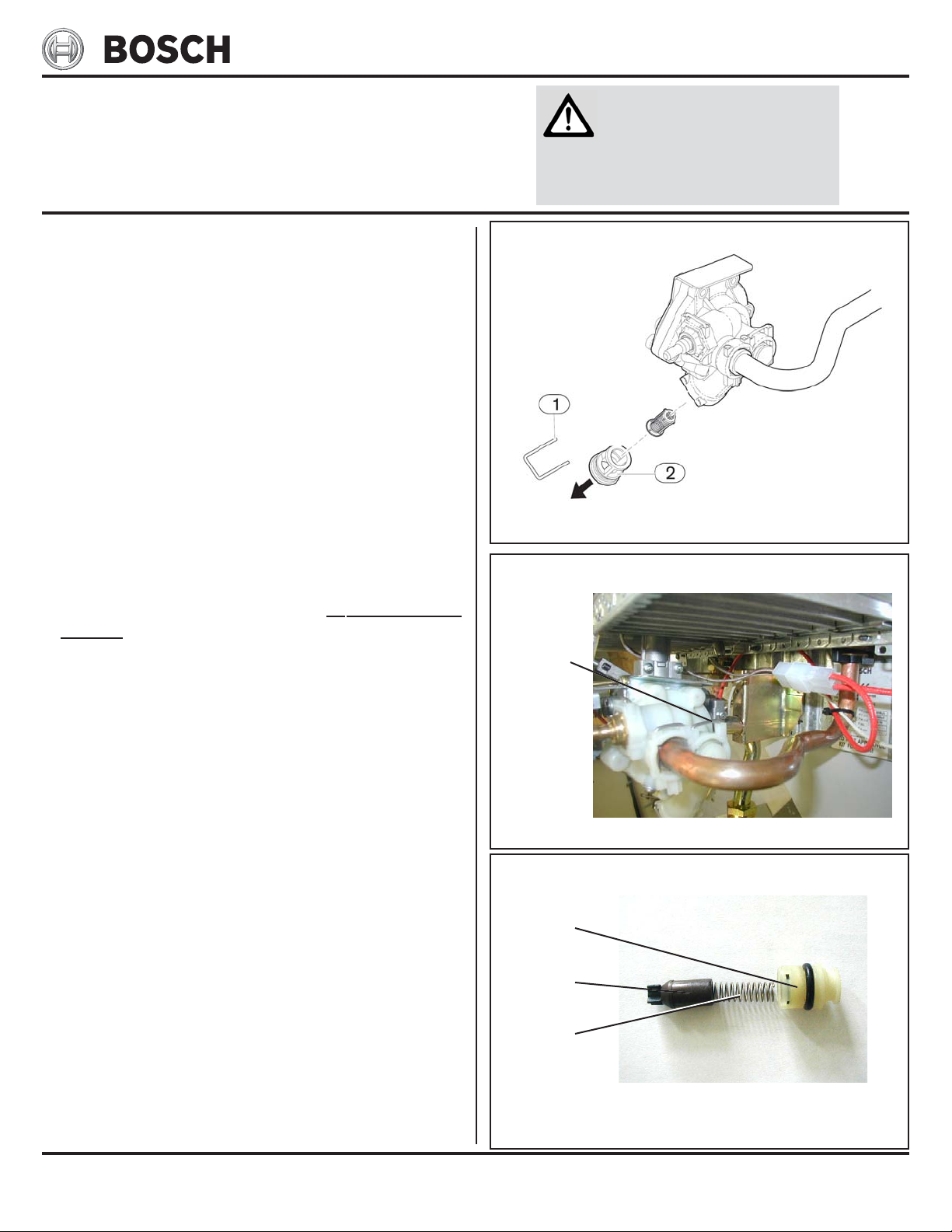
4. If temperatures are still too hot, increase water flow
by removing the water governor/restrictor. Shut off cold
water supply to heater and remove wire clip on volumetric water governor housing from right side of water valve behind water outlet pipe. (Fig. 2) Remove
retaining cap with o-ring and spring/cylinder assembly inside. (Fig. 3) Re-install retaining cap with lubricated o-ring and wir e clip only. No inner components
should be left inside. Operate heater with the flow
control turned all the way clockwise.
FIGURE 1
Removing Water Filter
FIGURE 2
Water governor
clip
Water Governor Location
FIGURE 3
Retaining
cap
Cylinder
Spring
Water Governor Location
©BBT NORTH AMERICA CORPORATION
Bosch Group
Bosch Water Heating
340 Mad River Park, Waitsfield, VT 05673
 Loading...