

Bosch Therm 4000 S, GWH12, GWH15, GWH18 Installation And Operating Manual
Installation and Operating Manual
Gas instantaneous water heaters
Therm 4000 S
6720813351-00.1V
GWH12/15/18 CTD E23/31 F6 O...
6 720 819 528 (2016/02) ZA
Read installation manual prior to installation of this unit!
Read user manual before putting this unit in operation!
Observe the warnings in the manuals!
The installation room must fulfill the ventilation requirements!
Installation by an authorised person only!

6 720 819 528 (2016/02) Therm 4000 S
2 | Index
Index
1 Key to symbols and safety instructions . . . . . . . . . . 3
1.1 Key to symbols . . . . . . . . . . . . . . . . . . . . . . . 3
1.2 General safety instructions . . . . . . . . . . . . . . 3
2 Product details . . . . . . . . . . . . . . . . . . . . . . . . . . . . . . . 5
2.1 EC Declaration of Conformity . . . . . . . . . . . . 5
2.2 Type overview . . . . . . . . . . . . . . . . . . . . . . . . 5
2.3 Material attached . . . . . . . . . . . . . . . . . . . . . 5
2.4 Rating plate . . . . . . . . . . . . . . . . . . . . . . . . . . 5
2.5 Description of appliance . . . . . . . . . . . . . . . . 5
2.6 Accessory (not supplied with the appliance) 5
2.7 Dimensions and minimum clearances . . . . . 6
2.8 Appliance layout . . . . . . . . . . . . . . . . . . . . . . 7
2.9 Electrical wiring diagram . . . . . . . . . . . . . . . 8
2.10 Specification . . . . . . . . . . . . . . . . . . . . . . . . . 9
3 Operation instructions . . . . . . . . . . . . . . . . . . . . . . . 10
3.1 Digital display - description . . . . . . . . . . . . 10
3.2 Before commissioning the appliance . . . . . 10
3.3 Switching the appliance on/off . . . . . . . . . . 10
3.4 Temperature control . . . . . . . . . . . . . . . . . . 11
3.5 Programming button . . . . . . . . . . . . . . . . . . 11
3.6 Draining the appliance . . . . . . . . . . . . . . . . 11
3.7 Codes of errors in the display . . . . . . . . . . . 12
3.8 Cleaning the front of the appliance . . . . . . 12
4 Regulations . . . . . . . . . . . . . . . . . . . . . . . . . . . . . . . . . 12
5 Installation (only by qualified contractors) . . . . . . 12
5.1 Important notes . . . . . . . . . . . . . . . . . . . . . . 13
5.2 Choice of installation site . . . . . . . . . . . . . . 13
5.2.1 Regulations concerning the installation
site . . . . . . . . . . . . . . . . . . . . . . . . . . . . . . . . 13
5.3 Minimum distances . . . . . . . . . . . . . . . . . . . 13
5.4 Fitting wall-mounting bar . . . . . . . . . . . . . . 14
5.5 Fitting the appliance . . . . . . . . . . . . . . . . . . 14
5.6 Water connection . . . . . . . . . . . . . . . . . . . . 14
5.7 Gas connection . . . . . . . . . . . . . . . . . . . . . . 15
5.8 Altitude of installation site region . . . . . . . . 15
5.9 Remote control connection . . . . . . . . . . . . 15
5.10 Commissioning of the appliance . . . . . . . . 16
6 Electrical connection (only by qualified
contractors) . . . . . . . . . . . . . . . . . . . . . . . . . . . . . . . . .16
6.1 Connecting the power cable . . . . . . . . . . . . 17
6.2 Replacing the power cable . . . . . . . . . . . . . 17
7 Regulating the gas (only for qualified
contractors) . . . . . . . . . . . . . . . . . . . . . . . . . . . . . . . . .17
7.1 Factory regulation . . . . . . . . . . . . . . . . . . . . 17
7.2 Service function . . . . . . . . . . . . . . . . . . . . . 17
7.3 Adjusting the appliance . . . . . . . . . . . . . . . 17
7.3.1 Access to the pressure heads . . . . . . . . . . . 17
7.3.2 Adjusting the maximum flow
(Parameter P1) . . . . . . . . . . . . . . . . . . . . . .18
7.3.3 Adjusting the minimum flow
(Parameter P2) . . . . . . . . . . . . . . . . . . . . . .18
7.3.4 Adjusting pressure in the burner
(Parameter P0) . . . . . . . . . . . . . . . . . . . . . .19
7.4 Factory default settings . . . . . . . . . . . . . . . 19
7.5 Changing the type of gas . . . . . . . . . . . . . . 19
8 Maintenance (only by qualified contractors) . . . . 19
8.1 Remove the front cover . . . . . . . . . . . . . . . 20
8.2 Periodic maintenance works . . . . . . . . . . . 20
8.3 Replacement of fuses (control box) . . . . . . 20
8.4 Start-up after completion of maintenance
works . . . . . . . . . . . . . . . . . . . . . . . . . . . . . . .20
9 Problems . . . . . . . . . . . . . . . . . . . . . . . . . . . . . . . . . . . 21
10 Environment / disposal . . . . . . . . . . . . . . . . . . . . . . . 22
11 Warranty Terms . . . . . . . . . . . . . . . . . . . . . . . . . . . . . 23
6 720 819 528 (2016/02)Therm 4000 S
Key to symbols and safety instructions | 3
1 Key to symbols and safety instructions
1.1 Key to symbols
Warnings
The following keywords are defined and can be used in this
document:
• NOTICE indicates a situation that could result in damage to
property or equipment.
• CAUTION indicates a situation that could result in minor to
medium injury.
• WARNING indicates a situation that could result in severe
injury or death.
• DANGER indicates a situation that will result in severe
injury or death.
Important information
Additional symbols
1.2 General safety instructions
These instructions are aimed at the owner, specialist
technicians and those qualified in gas, water, electricity,
heating installations.
▶ Before use, read and keep the operation manuals
(appliance, heating controller, etc.).
▶ Read the installation instructions (appliance, heating
controller, etc) before the installation.
▶ Pay attention to the safety and warning notices.
▶ Pay attention to national and regional regulations,
technical regulations and directives.
▶ Document works carried out.
If you smell gas
A gas leak could potentially cause an explosion. If you smell gas,
observe the following rules.
▶ Prevent flames or sparks:
– Do not smoke, use a lighter or strike matches.
– Do not operate any electrical switches or unplug any
equipment.
– Do not use the telephone or ring doorbells.
▶ Turn off the gas at the meter.
▶ Warn your neighbours and leave the building.
▶ Prevent anyone from entering the building.
▶ Well away from the building: call the fire brigade, police and
gas supplier.
Use as per regulations
The appliance may only be used for the production of DHW for
human consumption in domestic installations or equivalent
with intermittent use.
The appliance can only be installed outdoors.
Any other type of use is deemed improper. No liability is
accepted for any damage as a result of this.
Safety of electrical appliances for
domestic use and similar purposes
The following requirements apply in
accordance with EN 60335-1 in order to
prevent hazards from occurring when using
electrical appliances:
“This device can be used by children of 8
years and up as well and by people with
reduced physical, sensory or mental
capabilities or lacking in experience and
knowledge, if they are supervised and have
been given instruction in the safe use of the
device and understand the resulting
dangers. Children must not play with the
device. Cleaning and user maintenance may
not be performed by children without
supervision”
“If the power supply cable is damaged, in
order to avoid risks it must be replaced by
Warnings in this document are identified by a
warning triangle printed against a grey
background.
Keywords at the start of a warning indicate
the type and seriousness of the ensuing risk
if measures to prevent the risk are not taken.
This symbol indicates important information
where there is no risk to people or property.
Symbol Explanation
▶ Step in an action sequence
Cross-reference to another part of the document
•List entry
– List entry (second level)
Table 1

6 720 819 528 (2016/02) Therm 4000 S
4 | Key to symbols and safety instructions
the manufacturer or its customer service
department or a similarly qualified person.”
Installation, commissioning and maintenance
The installation, commissioning and maintenance may only be
carried out by an authorised contractor.
▶ Check the tightness of the connections to the device (gas
and water).
▶ Only fit original spare parts.
Inspection and maintenance
Regular inspection and maintenance are essential for the safe
and environmentally-sound operation of the heating system.
We recommend taking out an annual inspection and
maintenance contract with the manufacturer.
▶ Work should only be carried out by an authorised
contractor.
▶ Immediately remove any faults detected.
Any situation that does not meet the conditions described in
the manual must be duly assessed by a qualified, contractor. In
the event that it is approved for use, the technician shall adapt
the maintenance requirements to the wear and tear and
associated conditions as well as the standards and
requirements of the market and the particular application.
Modifications and repairs
Unprofessional modifications to the appliance or other parts of
the heating system can result in injury and/or damage to
property or equipment.
▶ Have any work carried out only by an authorised
contractor.
▶ Do not remove the appliance case.
▶ Do not modify the appliance or other parts of the heating
system in any way.
Electrical work
Electrical work must only be carried out by a qualified
electrician.
▶ Before starting electrical work:
– Isolate the mains electrical supply and secure against
unintentional reconnection.
– Check for zero potential.
▶ Also observe connection diagrams of other system
components.
Open flue operation
The installation room must be adequately ventilated if the
appliance draws its combustion air from the room.
▶ Consult an authorised contractor to ensure the ventilation
requirements are met:
– if structural modifications are made (e.g. replacing
windows and doors)
– if appliances are subsequently installed which route
extract air to the outside (e.g. extract air fans, kitchen
fans or air conditioning units).
▶ Never cover or reduce the size of ventilation apertures.
Handover to the user
When handing over, instruct the user how to operate the
heating system and inform him about its operating conditions.
▶ Explain how to operate the heating system and draw the
user's attention to any safety-relevant action.
▶ Explain that modifications and repairs must only be carried
out by an authorised contractor.
▶ Point out the necessity of inspection and servicing for safe
and environmentally compatible operation.
▶ Leave the installation instructions and the operating
instructions with the user.
6 720 819 528 (2016/02)Therm 4000 S
Product details | 5
2 Product details
GWH appliances are appliances for producing hot water ready
for operation at the simple touch of a remote control button.
2.1 EC Declaration of Conformity
This appliance meets the requirements of the European
Directives 2009/142/EC, 2006/95/EC, 2004/108/EC and
corresponds to the approval sample described in the relevant
CE test certificate.
The appliance has been EN 26 tested.
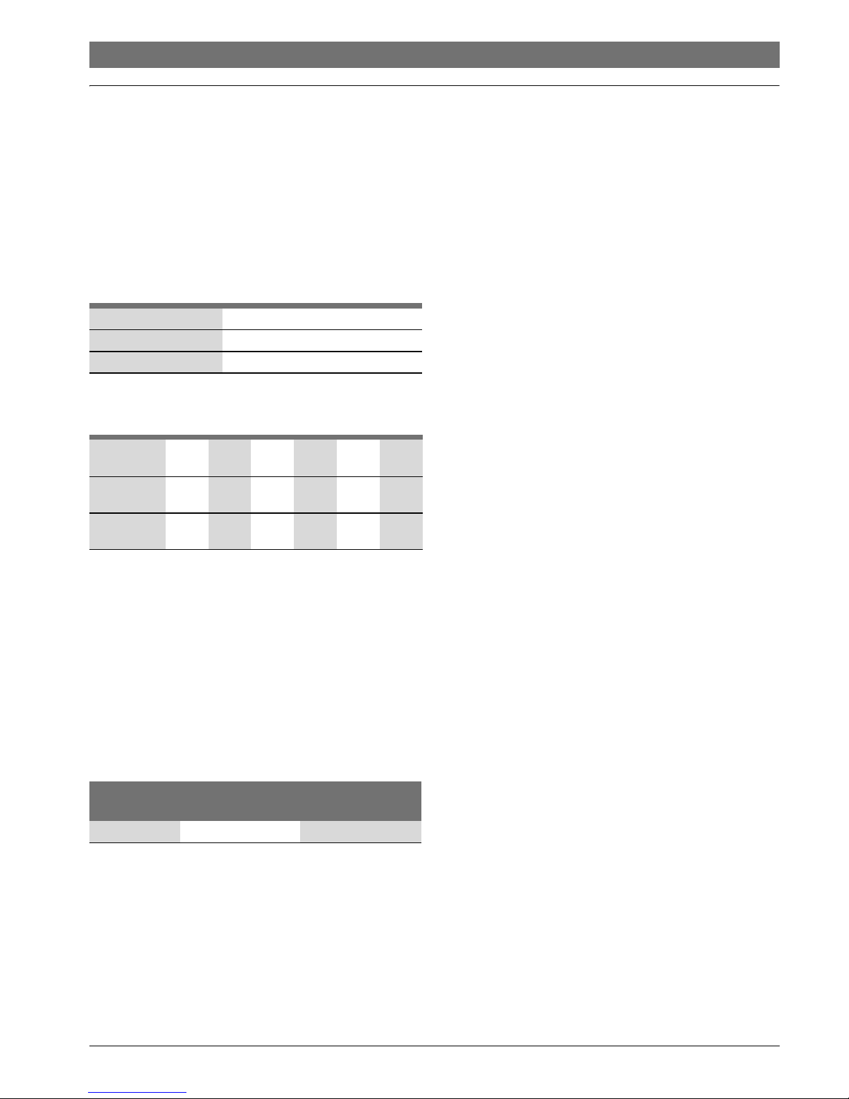
2.2 Type overview
[GWH] Gas instantaneous water heater
[12] Capacity (l/min)
[CT] Thermostatic
[D] Digital user interface
[E] Electric ignition
[23] Appliance set for natural gas
[31] Appliance set for LPG
[F6] Room sealed
[O] Outdoor installation
The code number indicates the gas group according to EN 437:
2.3 Material attached
• Gas instantaneous water heater
•Fasteners
• Appliance documentation
• Remote control
• Anti freeze kit
2.4 Rating plate
The rating plate is located on the outside of the appliance, on
the bottom.
It contains details of the output of the appliance, the order
number, the approval data and the date of manufacture in
encoded form (FD).
2.5 Description of appliance
• Room sealed wall-mounted appliance
• Remote control with multifunctional display panel
• Appliance for operating with LPG
• Electronic ignition
•Water flow sensor
• Temperature sensors for monitoring the temperature of the
cold and hot water of the appliance.
•Safety devices:
– Ionisation electrode
–Thermofuse
– Hot water temperature sensor
– Control box
–Air temperature sensor
• Electrical connection: 230 V, 50 Hz
2.6 Accessory (not supplied with the appliance)
•Gas conversion kits
Model GWH12/15/18 CTD E23/31 F6 O...
Category (gas type) I
3B/P
Type of installation A
3
Table 2
GWH12 CT DE23
31
F6 O
GWH15 CT DE23
31
F6 O
GWH18 CT DE23
31
F6 O
Table 3
Code numbers Wobbe Index
(W
S
) (15 °C)
Gas type
31 20.2-21.3 kWh/m
3
LPG group3R
Table 4
6 720 819 528 (2016/02) Therm 4000 S
6 | Product details
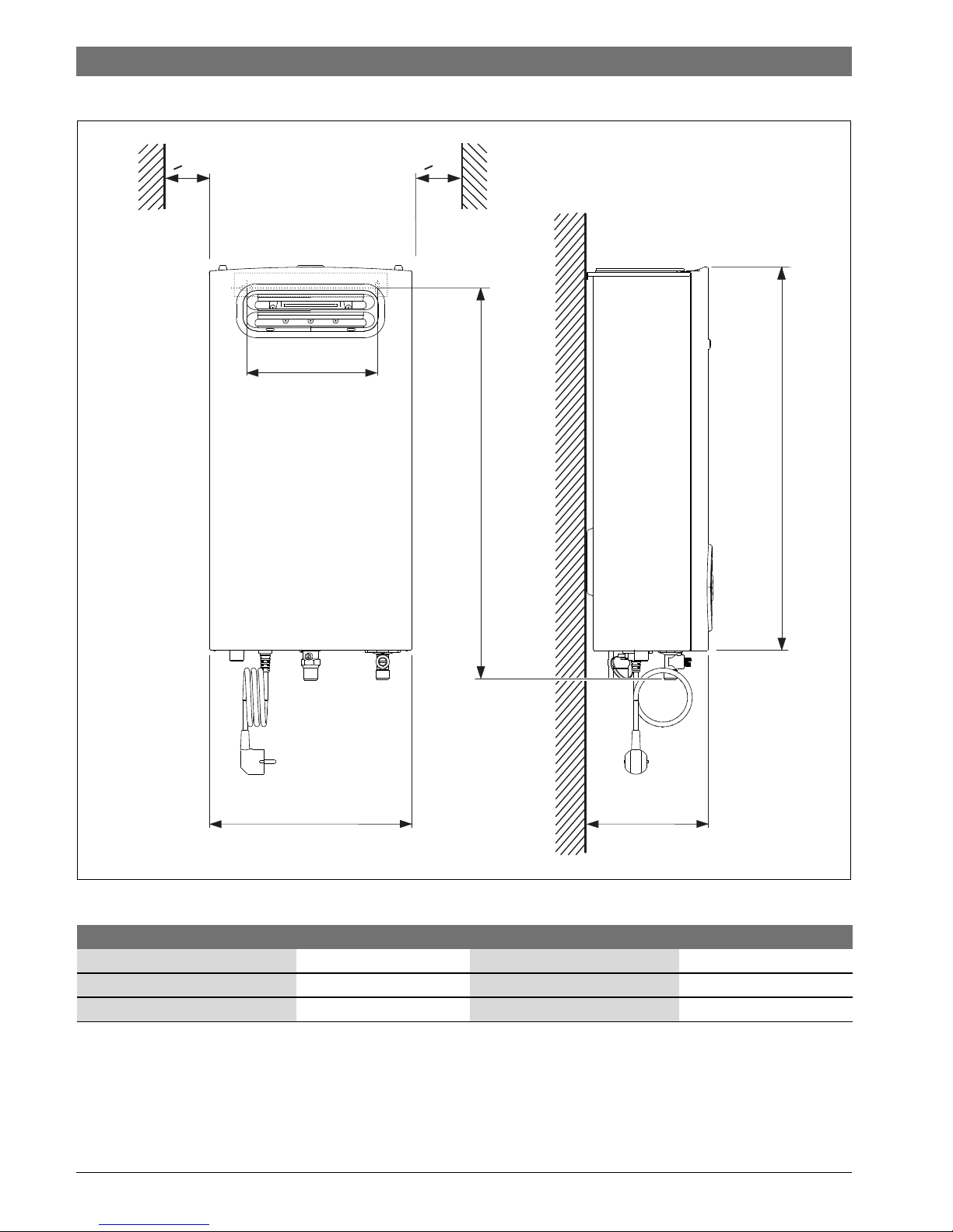
2.7 Dimensions and minimum clearances
Fig. 1 Dimensions (in mm)
B
C
230
A
583
6720813351-01.1V
>10 >10
A B C
GWH12 300 568 170
GWH15 300 568 170
GWH18 364 568 175
Table 5 Dimensions (in mm)
6 720 819 528 (2016/02)Therm 4000 S
Product details | 7
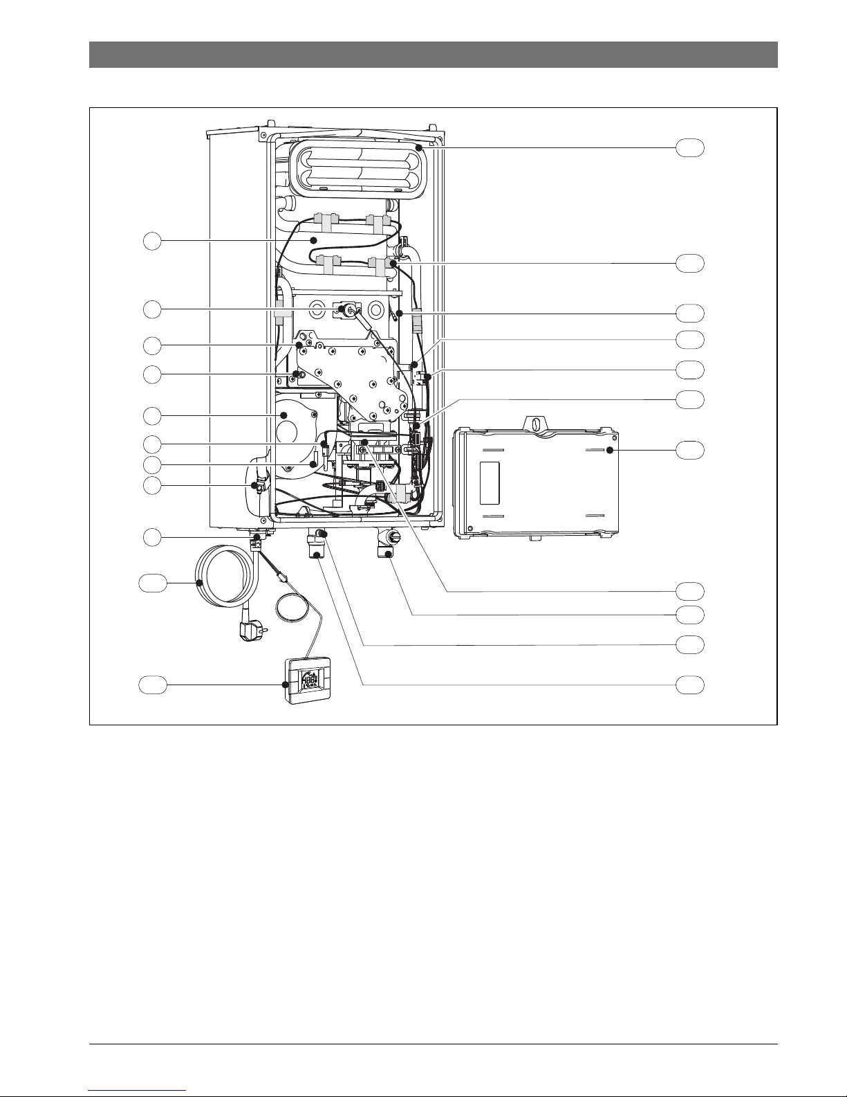
2.8 Appliance layout
Fig. 2
[1] Combustion chamber
[2] Monitoring electrode
[3] Burner
[4] Air pressure head in the box
[5] Fan
[6] Air temperature sensor of the box
[7] Thermofuse
[8] Hot water temperature sensor
[9] Water outlet
[10] Connecting lead with plug
[11] Remote control
[12] Combustion gas collector
[13] Anti freeze kit
[14] Ignition electrode
[15] Gas pressure head in the burner
[16] Cold water temperature sensor
[17] Water flow sensor
[18] Control box
[19] Gas valve
[20] Water inlet
[21] Incoming gas pressure head
[22] Gas
10
6720813351-02.1V
22
18
20
21
6
7
1
5
8
9
12
15
19
3
13
16
4
11
2
14
17
6 720 819 528 (2016/02) Therm 4000 S
8 | Product details
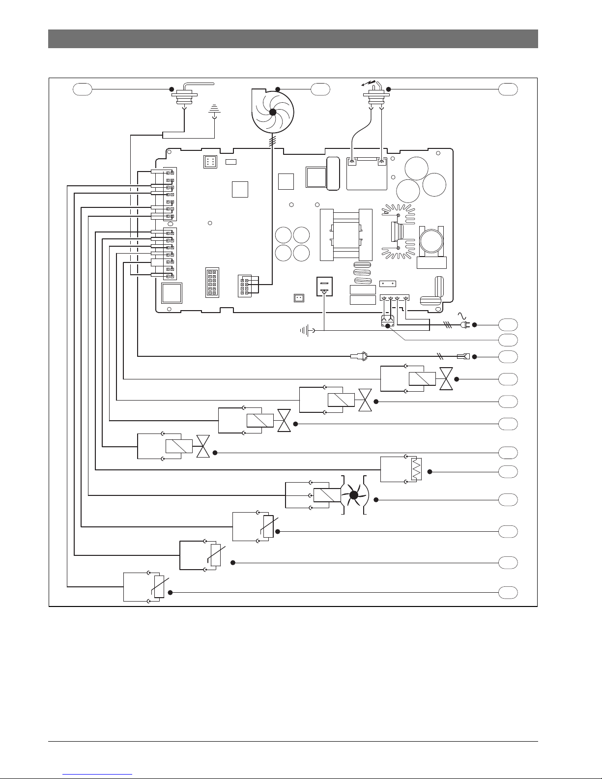
2.9 Electrical wiring diagram
Fig. 3 Electrical diagram
[1] Monitoring electrode
[2] Fan
[3] Ignition electrode
[4] Supply
[5] Connection for anti freeze kit
[6] Connection for remote control
[7] Electrovalve 1
[8] Electrovalve 2
[9] Electrovalve 3
[10] Electrovalve 4
[11] Thermofuse
[12] Water flow sensor
[13] Air temperature sensor of the box
[14] Outgoing water temperature sensor
[15] Incoming water temperature sensor
6720804089-10.1V
1 32
4
6
7
8
9
10
11
12
13
14
15
230 V
AC
M1
5
 Loading...