

Page 1
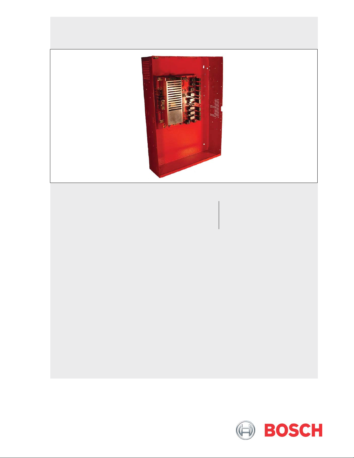
FPP-RNAC-8A-4C
Operation and Installation Guide
EN
Remote NAC Power
Supply
Page 2

FPP-RNAC-8A-4C | Operation and Installation Guide |
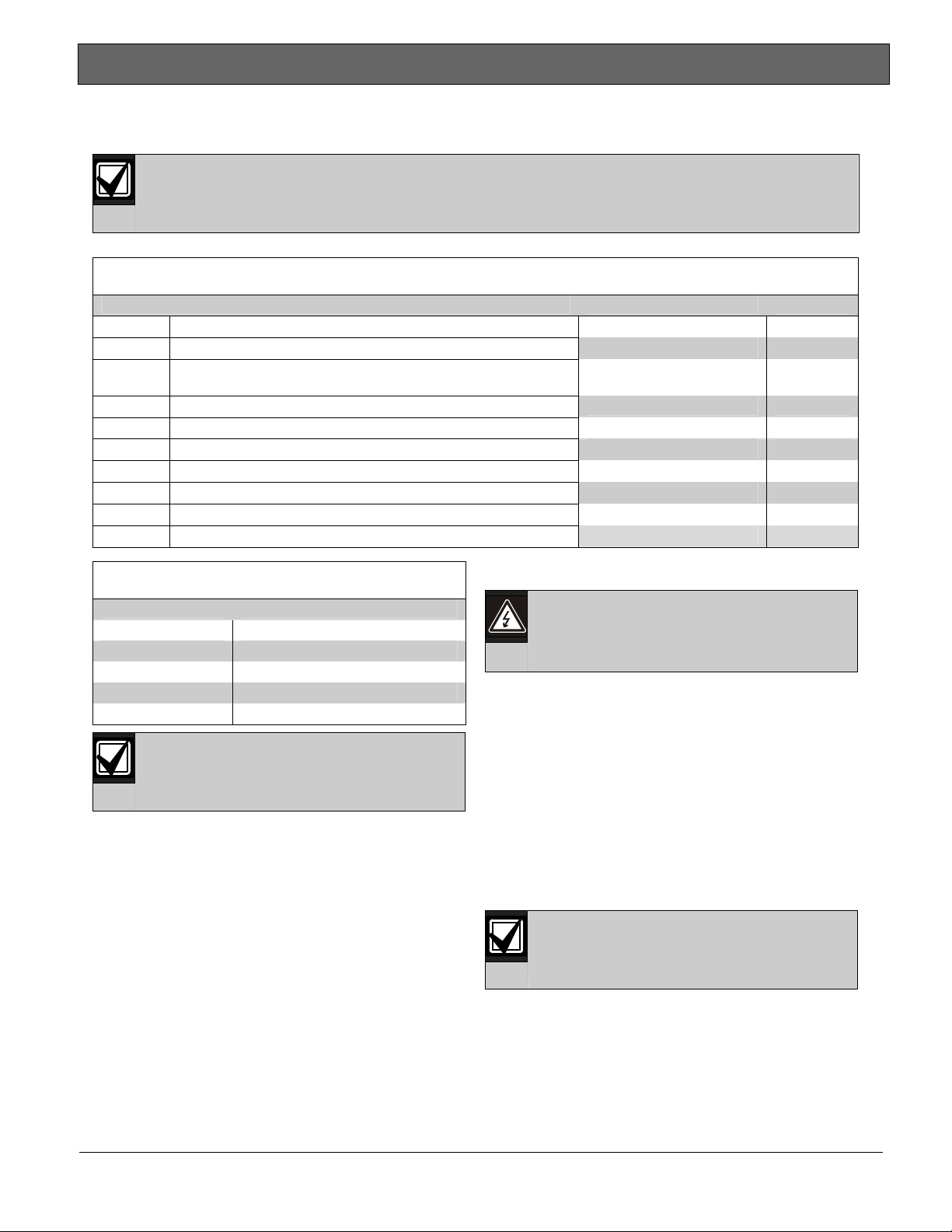
Notice to Users, Installers, Authorities
Having Jurisdiction, and other involved
parties:
This product incorporates fieldprogrammable software. In order for the
product to comply with the requirements
in the Standard for Control Units and
Accessories for Fire Alarm Systems,
UL864, certain programming features or
options must be limited to specific values
or not used at all as indicated below.
Program Feature or Option Permitted in UL864?
(Y/N)
Ground Fault Detection
N Jumper in place (enabled)
disable
Possible Settings Settings Permitted in
UL864
Jumper in place (enabled),
Jumper removed (disabled)
only
2 Bosch Security Systems, Inc. | 8/09 | F01U025431-02
Page 3

.
Contents
1.0 Overview ...........................................................4
1.1 Module Control...................................................4
1.1.1 Option Bus Control ...........................................4
1.1.2 Conventional NAC Input Control ...................4
1.2 Output Bell Operation .......................................4
1.3 Power Management..........................................4
1.4 Low AC Line Detection .....................................4
1.5 Ground Fault Monitoring...................................4
1.6 Circuit Supervision ............................................4
1.7 Overvoltage Supervision ..................................4
1.8 Expander Supervision....................................... 5
1.9 Auxiliary Power Supply.....................................5
2.0 Installing the FPP-RNAC-8A-4C...................5
2.1 FPP-RNAC-8A-4C Board Installation.............6
2.2 Enclosure Installation........................................ 6
3.0 Wiring the FPP-RNAC-8A-4C........................8
3.1 AC Power Connections ....................................8
3.2 Battery Connections (24 VDC Only).............10
3.3 Option Bus Connections.................................14
3.4 NAC Input Connections..................................14
3.5 Trouble Relay Connections ...........................15
3.6 Auxiliary Output Connections ........................15
3.7 NAC Output Connections...............................15
3.7.1 NAC Circuits....................................................15
3.7.2 Auxiliary Circuits .............................................16
3.7.3 EOL Reference Programming........................16
4.0 DIP Switch and Option Bus Settings........17
4.1 Switch S1...........................................................17
4.2 Switch S2...........................................................18
4.3 Conventional (Polarity Reversal) Inputs 1
and 2..................................................................19
4.4 Option Bus Address ........................................20
4.5 NAC Input Variable .........................................20
4.6 AC Fail Time Delay .........................................20
5.0 FPP-RNAC-8A-4C Local Status Display ..21
6.0 Specifications.................................................23
FPP-RNAC-8A-4C | Operation and Installation Guide |
Figures
Figure 1: FPP-RNAC-8A-4C Remote NAC
Power Supply Board.................................. 5
Figure 2: FPP-RNAC-8A-4C Enclosure and
Board Installation ....................................... 7
Figure 3: AC Power Connections............................. 9
Figure 4: Install Ferrite Core .....................................9
Figure 5: Battery Connections Inside
FPP-RNAC-8A-4C Enclosure ................ 10
Figure 6: Battery Connections Using an External
Battery Case ............................................. 11
Figure 7: Wiring the Option Bus .............................14
Figure 8: Wiring the NAC Inputs............................. 14
Figure 9: Wiring the Trouble Relay ........................ 15
Figure 10: Wiring the Auxiliary Outputs................... 15
Figure 11: Wiring the NAC outputs and EOL.......... 16
Figure 12: Auxiliary Power Configuration................ 16
Figure 13: FPP-RNAC-8A-4C LEDs ........................ 22
Tables
Table 1: Wire Gauge Calculations................................ 8
Table 2: Wire Gauge Table (based on solid wire)...... 8
Table 3: Standby Time Calculation............................. 12
Table 4: Calculating the Required Battery Size........ 12
Table 5: Standby Load Battery Capacity (in ampere-
hours [Ah]) ................................................ 13
Table 6: Alarm Load Battery Capacity (in ampere-
hours [Ah])) ............................................... 13
Table 7: DIP Switch S1 Settings ................................. 17
Table 8: DIP Switch S2 Settings ................................. 18
Table 9: Using Conventional Inputs 1 and 2 to
Operate Outputs (Switch 2,
Position 0) ................................................. 19
Table 10: Local Status Display LED Functions......... 21
Table 11: Specifications ............................................... 23
Bosch Security Systems, Inc. | 8/09 | F01U025431-02 3
Page 4
FPP-RNAC-8A-4C | Operation and Installation Guide | 1.0 Overview
1.0 Overview
The FPP-RNAC-8A-4C is a Remote Notification
Appliance Circuit (NAC) Power Supply designed to
add four additional NACs (NFPA 72 Class B, Style Y
or Class A, Style Z) to a Fire Alarm Control Panel
(FACP).
The FPP-RNAC-8A-4C is supervised by the control
panel. It consists of the controller board, backup
batteries, and enclosure.
The FPP-RNAC-8A-4C is also compatible with any
UL Listed control unit utilizing:
• reverse polarity supervised notification appliance
circuit (NAC) outputs, and
• 12 or 24 VDC regulated outputs.
Each output can be configured individually as a NAC
or constant 24 V auxiliary power supply.
1.1 Module Control
1.1.1 Option Bus Control
The FPP-RNAC-8A-4C can connect to the Option
Bus of the FPA-1000 or FPD-7024 Fire Alarm
Control/Communicator.
Refer to Section
14 for information on wiring.
page
1.1.2 Conventional NAC Input Control
For conventional panels, the FPP-RNAC-8A-4C
connects using the FACP’s NAC outputs that conform
to NFPA 72 Class A or B. Please refer to the control
panel’s NAC compatibility information.
1.2 Output Bell Operation
The FPP-RNAC-8A-4C can generate three pulsed
bell patterns on command in addition to steady
activation of the output:
• Pulsed: 60 PPM (0.5 sec On, 0.5 sec Off)
• NFPA Temporal: In compliance with ANSI
standard S3.41: 0.5 sec On, 0.5 sec Off, 0.5 sec
On, 0.5 sec Off, 0.5 sec On, 1.5 sec Off, and so
on.
• California March: 120 ppm (0.25 sec on,
0.25 sec off).
You can also implement SYNC protocols:
• Wheelock SYNC Protocol
• Gentex SYNC Protocol
• System Sensor SYNC Protocol
3.3 Option Bus Connections on
All outputs are synchronized if the
conventional inputs are activating the
FPP-RNAC-8A-4C.
For option bus synchronization
information, refer to the control panel
documentation.
1.3 Power Management
The controlling section of the board has uninterruptible power. If AC line voltage is lost, the
power supply switches to battery backup.
1.4 Low AC Line Detection
Sensing circuitry detects a line input voltage below
85 VAC, then switches from the primary AC Line
voltage to battery backup.
1.5 Ground Fault Monitoring
The option bus and polarity reversal inputs are
electrically isolated from the local power supply and
indicating circuits. The FPP-RNAC-8A-4C supervises
itself for grounded field connections and indicates a
fault condition if one is found. This feature can be
disabled by opening Switch S4.
For UL864 installations, do not disable
ground fault monitoring.
1.6 Circuit Supervision
Each NAC is supervised for short-circuit and open
conditions using an end-of-line (EOL) resistor on the
loop. Devices on these loops must have a blocking
diode on their input so that the EOL supervision
resistor can be read when the polarity of the output is
reversed in the standby state. The devices activate
when the polarity is switched back to normal in an
alarm state. The EOL is programmable from 1 kΩ to
20 kΩ. This allows existing systems to be retrofitted.
1.7 Overvoltage Supervision
The power supply output is monitored for overvoltage
conditions. If an overvoltage condition exists (30 V or
more on battery leads without the battery connected),
the trouble relay and EOL relays open. In addition,
the trouble LED lights. On the option bus, AC fail,
ground fault, and NAC troubles are initiated.
4 Bosch Security Systems, Inc. | 8/09 | F01U025431-02
Page 5
FPP-RNAC-8A-4C | Operation and Installation Guide |
.
1.8 Expander Supervision
A watchdog supervises the operation of the
FPP-RNAC-8A-4C processor and attempts to restart
it if it fails. If the processor does not restart, or the
power fails entirely, the installer-supplied EOL device
1.9 Auxiliary Power Supply
The FPP-RNAC-8A-4C can be wired to supply
unsupervised constant auxiliary power through its
NAC outputs. Refer to Section
on page
16 for additional information.
3.7.2 Auxiliary Circuits
disconnects from the input to report the trouble
condition. If power is available, the System Trouble
LED lights if the system encounters an error.
2.0 Installing the FPP-RNAC-8A-4C
The FPP-RNAC-8A-4C board and the enclosure are shipped together. The board, however, needs to be
mounted into the enclosure. Hardware for mounting the board in the enclosure is supplied in the hardware
pack.
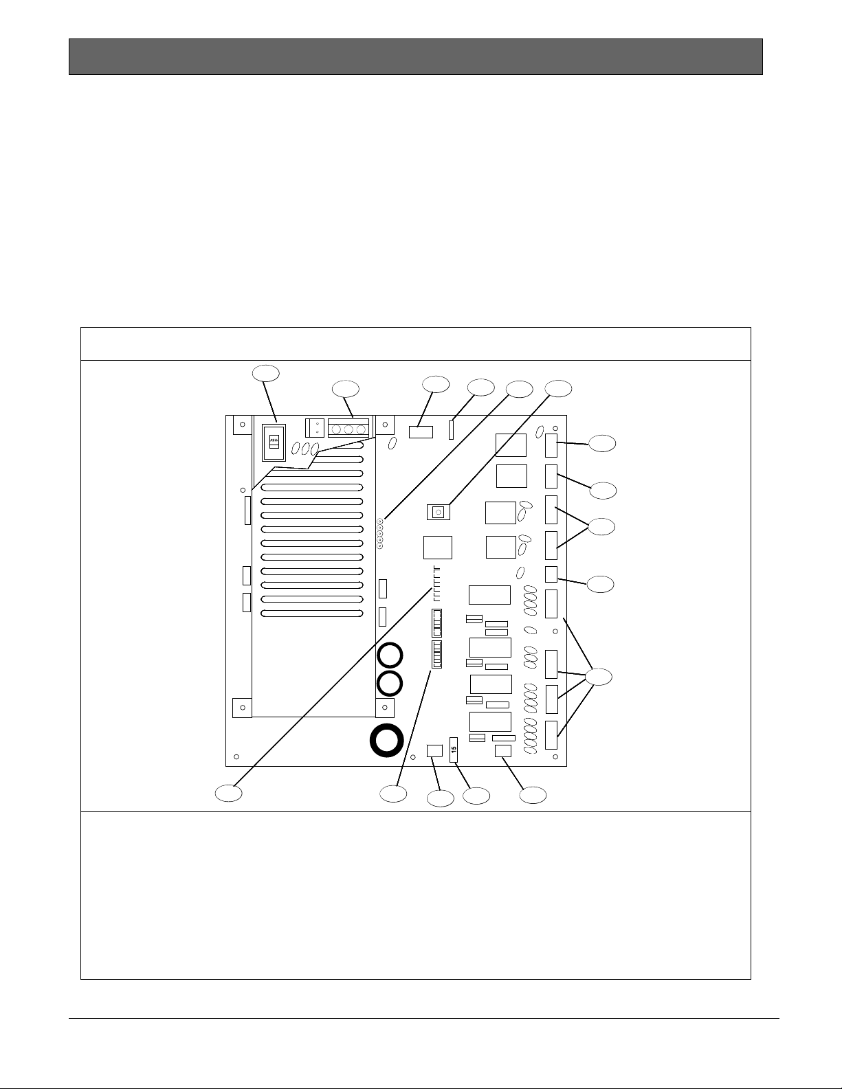
Figure 1: FPP-RNAC-8A-4C Remote NAC Power Supply Board
1
OPTION BUS
R Y G B
REPLACE WITH 15A
BLADE TYPE FUSE
3
TROUBLE
RESET
2
FLASH
PROGRAMMING
PORT
GROUND FAULT
OPEN = DISABLE
CLOSE = ENABLE
INPUT ACTIVE
AC OK
SYSTEM TROUBLE
GROUND FAULT
TROUBLE 4
TROUBLE 3
TROUBLE 2
TROUBLE 1
4
BOSCH
- AUX POWER +- BATTERY +
5
4998149856
6
AC
T
R
O
U
7
B
L
E
T
R
O
U
B
L
E
8
I
N
P
U
T
2
9
I
N
P
U
T
1
EOL
REF
10
O
U
T
P
U
T
4
O
U
T
P
U
T
3
11
O
U
T
P
U
T
2
O
U
T
P
U
T
1
16
1 AC Input Select Switch 120/240 VAC
2 AC Power Input 120/240 VAC
3 Option bus
4 Ground fault switch
5 Flash programming port
6 TROUBLE RESET button
7 AC trouble relay output
8 Trouble relay output
15
14
13
12
9 NAC inputs
10 EOL reference resistor (1kΩ to 20kΩ)
11 NAC outputs
12 Auxiliary 24V filtered and regulated output
power
13 Replaceable 15A fuse
14 Battery input
15 Configuration DIP switches
16 Status LEDs
Bosch Security Systems, Inc. | 8/09 | F01U025431-02 5
Page 6

FPP-RNAC-8A-4C | Operation and Installation Guide | 2.0 Installing the FPP-RNAC-8A-4C
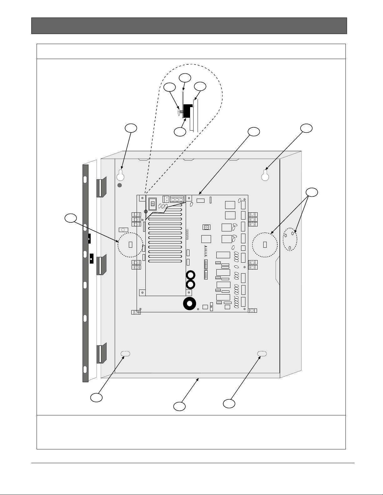
2.1 FPP-RNAC-8A-4C Board
Installation
The FPP-RNAC-8A-4C board is staticsensitive. Touch ground before handling
1. Connect the ground wire.
2. Insert the two support posts into the control
3. Slide the top of the board into the retainer tabs
4. To secure the bottom of the board, screw the two
the board. Doing so discharges any
static electricity in your body.
retainer holes as shown in
(the slots under the top of the frame). When it is
in the retainner tabs, the board rests on the two
support posts.
bottom corners through the support posts and
through to the enclosure.
Figure 2 on page 7.
2.2 Enclosure Installation
1. Use the enclosure as a template and mark the
top mounting holes on the mounting surface.
Ensure that enough clearance exists to open the
door for maintenance.
2. Pre-start the mounting screws for the two holes.
Slide the enclosure onto the mounting screws so
that the screws move up into the thinner section
of the holes. Tighten the screws.
3. Screw the remaining two screws into the bottom
mounting holes.
4. Knock out the desired wire entrances on the
enclosure.
Refer to
Figure 2 on page 7 for details.
6 Bosch Security Systems, Inc. | 8/09 | F01U025431-02
Page 7
FPP-RNAC-8A-4C | Operation and Installation Guide | 2.0 Installing the FPP-RNAC-8A-4C
.
Figure 2: FPP-RNAC-8A-4C Enclosure and Board Installation
1
4
2
5
6
3
OPTION BUS
R Y G B
FLASH
PROGRAMMING
PORT
TROUBLE
RESET
REPLACE WIT H 15A
BLADE TYPE FUSE
INPUT ACTIVE
AC OK
SYSTEM TROUBLE
GROUND FAULT
TROUBLE 4
TROUBLE 3
TROUBLE 2
TROUBLE 1
GROUND FAULT
OPEN = DISABLE
CLOSE = ENABLE
- AUX POWER +- BATTERY +
BOSCH
4998149856
1
AC
T
R
O
U
B
L
E
T
R
O
U
B
L
E
I
N
P
U
T
2
I
N
P
U
T
1
EOL
REF
O
U
T
P
U
T
4
O
U
T
P
U
T
3
O
U
T
P
U
T
2
O
U
T
P
U
T
1
5
6
5
7
5
1 FPP-RNAC-8A-4C Printed circuit board
2 Retainer hole in enclosure
3 Support post
4 Mounting Screw
5 Mounting screw holes
6 Wire entrance knockouts
7 Enclosure
Bosch Security Systems, Inc. | 8/09 | F01U025431-02 7
Page 8
FPP-RNAC-8A-4C | Operation and Installation Guide | 3.0 Wiring the FPP-RNAC-8A-4C
3.0 Wiring the FPP-RNAC-8A-4C
All terminals are fully protected against electrostatic discharge (ESD) and transients.
Use wire gauge based on Table 1 and Table 2. The terminals can accommodate up to 12 AWG (2.0 mm) wire.
Table 1: Wire Gauge Calculations
Line No. Description Calculation
1 Guaranteed minimum NAC voltage at full load.
2
3 Maximum wiring voltage drop
4 Total load for a given NAC
5 Maximum allowable line resistance
6 Total wiring run length (feet)
7 Total wire needed
8 Maximum wire resistance per foot
9 Choose a wire size with a resistance per foot less than Line 7.
Minimum operating voltages (largest value of appliance on
circuit)
Table 2: Wire Gauge Table (based on solid wire)
AWG B&S Gauge Ohms per Foot
12 (2.0 mm) 0.00162
14 (1.6 mm) 0.00258
16 (1.3 mm) 0.00409
18 (1.0 mm) 0.00651
NFPA 72 requires the use of 18 AWG
(1.0 mm) or larger diameter wire in fire
applications.
3.1 AC Power Connections
AC Power runs to the L (Hot VAC), G (Ground), and
N (Neutral) terminals.
120 VAC or 240 VAC with 8 A capacities should feed
the local power supply. The output voltage is a filtered
27.6 VDC (500 mV ripple maximum) under all
conditions.
A trouble condition is registered, but not indicated, if
AC power fails. A programmable time delay (refer to
Section
Subtract line 2 from line 1.
Divide line 3 by line 4.
Multiply line 6 by line 2.
Divide line 5 by line 7.
Disconnect all power (AC and battery)
before servicing the FPP-RNAC-8A-4C.
Wait 60 sec before handling any
connections.
4.6 AC Fail Time Delay on page 20) allows
the indication of AC Failure to be delayed by 0, 6, 12,
or 24 hrs. The default is 0 hrs.
Refer to
Figure 3 on page 9 for wiring details.
Value
27.4 V
Remember to select the appropriate
voltage range for the AC input before
applying any power to the product.
8 Bosch Security Systems, Inc. | 8/09 | F01U025431-02
Page 9

FPP-RNAC-8A-4C | Operation and Installation Guide |
.
Figure 3: AC Power Connections Figure 4: Install Ferrite Core
4
3
1
1 AC input select switch
2 AC power terminal
3 Ground
4 Neutral
5 Line (120 VAC or 240 VAC)
6 Ferrite core
Install the Line and Neutral power connections through the ferrite core as shown in
2
LNG
5
6
1 Ferrite core
Figure 4.
Bosch Security Systems, Inc. | 8/09 | F01U025431-02 9
Page 10

FPP-RNAC-8A-4C | Operation and Installation Guide |
3.2 Battery Connections (24 VDC Only)
The backup battery plugs into the terminals marked BATTERY+ and BATTERY- at the lower center of the
board (refer to
Figure 5). The FPP-RNAC-8A-4C requires two backup batteries in series.
Figure 5: Battery Connections Inside FPP-RNAC-8A-4C Enclosure
OPTION BUS
R Y G B
GROUND FAULT
4998149856
BOSCH
OPEN = DISABLE
CLOSE = ENABLE
AC
T
R
O
U
B
L
E
T
R
O
U
B
L
TROUBLE
RESET
FLASH
PROGRAMMING
PORT
INPUT ACTIVE
AC OK
SYSTEM TROUBLE
GROUND FAULT
TROUBLE 4
TROUBLE 3
TROUBLE 2
TROUBLE 1
REPLACE WITH 1 5A
BLADE TYPE FUSE
4
E
I
N
P
U
T
2
I
N
P
U
T
1
EOL
REF
O
U
T
P
U
T
4
O
U
T
P
U
T
3
O
U
T
P
U
T
2
O
U
T
P
U
T
1
- AUX POWER +- BATTERY +
5
4
4
3
3
3
1
2
1 Battery 1
2 Battery 2
3 Red (+)
4 Black (-)
5 BATTERY terminals
1 2
10 Bosch Security Systems, Inc. | 8/09 | F01U025431-02
Page 11

FPP-RNAC-8A-4C | Operation and Installation Guide |
.
Figure 6: Battery Connections Using an External Battery Case
1
1 BATB-40 Battery Case
2 Conduit, 20 ft (6.1 m) maximum
3 Black wire (-)
4 Red wire (+)
5 To field
6 Power Limited wiring area
7 Non-Power Limited wiring area
OPTION BUS
R Y G B
GROUND FAULT
4998149856
BOSCH
7
3
OPEN = DISABLE
CLOSE = ENABLE
AC
T
R
O
U
B
L
E
T
R
O
U
B
L
TROUB LE
RESET
FLASH
PROGRAMMING
PORT
INPUT ACTIVE
AC OK
SYSTEM TROU BLE
GROUND FAULT
TROUBLE 4
TROUBLE 3
TROUBLE 2
TROUBLE 1
REPLACE WITH 15A
BLADE TYPE FUSE
E
I
N
P
U
T
2
I
N
P
U
T
1
EOL
REF
O
U
T
P
U
T
4
O
U
T
P
U
T
3
O
U
T
P
U
T
2
O
U
T
P
U
T
1
- AUX POWER +- BATTERY +
6
5
2
4
Battery wires must be 12 AWG (2.34 mm) minimum.
Ensure that a minimum of ¼ in. (6.4 mm) of space exists between all power wiring and field wiring.
Bosch Security Systems, Inc. | 8/09 | F01U025431-02 11
Page 12

FPP-RNAC-8A-4C | Operation and Installation Guide |
You can use the format in
Table 3 to calculate the required battery size to support the system. Use Table 4 and
Table 5 on page 13 to estimate the required battery size.
Table 3: Standby Time Calculation
Device Quantity Standby
Current for
Each Device
FPP-RNAC-8A-4C
1 150 mA 150 mA 150 mA 150 mA
Total Standby
Current for Each
Device (Quantity x
Standby Current for
Each Device)
Alarm Current
for Each Device
Total Alarm
Current for Each
Device (Quantity x
Alarm Current for
Each Device)
Remote NAC Power
Supply
Grand Total
Standby Current
Grand Total
Alarm Current
Table 4: Calculating the Required Battery Size
Descriptions Calculations
Grand Total Standby Current (in amps [A]) CS
Total Hours of Standby Required (usually 24 or 60) HS
Total Standby Capacity (multiply CS x HS) TS = CS x HS
Grand Total Alarm Current (in amps) CA
Divide by 0.6 CAA = CA ÷ 0.6
Total Hours of Alarm Time Required (usually 0.083 [5 min.] or 0.25 [15 min.]) HA
Total Hours Capacity (multiply CAA x HA) TA = CAA x HA
Total Alarm Capacity Required (add TA + TS) TC = TA + TS
Required Capacity with 20% Derating (TC x 1.2) C = TC x 1.2
12 Bosch Security Systems, Inc. | 8/09 | F01U025431-02
Page 13

FPP-RNAC-8A-4C | Operation and Installation Guide |
.
Table 5: Standby Load Battery Capacity (in ampere-hours [Ah])
Capacity Required for: Total Standby Current
12 hr 24 hr 36 hr 48 hr 60 hr 72 hr
100 to 300 mA 4.0 7.9 11.9 15.8 19.8 23.8
300 to 500 mA 6.6 13.2 19.8 26.4 33.0 39.6
500 to 700 mA 9.2 18.5 27.7 37.0
700 to 900 mA 11.9 23.8 35.6
900 mA to 1.1 A 14.5 29.0
1.1 to 1.3 A 172 34.3
1.3 to 1.5 A 19.8 39.6
1.5 to 1.7 A 22.4
1.7 to 1.9 A 25.1
1.9 to 2.1 A 27.7
2.1 to 2.3 A 30.4
2.3 to 2.5 A 33.0
2.5 to 2.7 A 35.6
Table 6: Alarm Load Battery Capacity (in ampere-hours [Ah]))
Total Alarm Current Capacity Required for:
5 min 10 min 15 min 30 min 45 min 60 min
200 to 500 mA 0.0 0.1 0.1 0.3 0.4 0.6
500 mA to 1.0 A 0.1 0.2 0.3 0.6 0.8 1.1
1.0 to 2.0 A 0.2 0.4 0.6 1.1 1.7 2.2
2.0 to 3.0 A 0.3 0.6 0.8 1.7 2.5 3.3
3.0 to 4.0 A 0.4 0.7 1.1 2.2 3.3 4.4
4.0 to 5.0 A 0.5 0.9 1.4 2.8 4.1 5.5
5.0 to 6.0 A 0.6 1.1 1.7 3.3 5.0 6.6
6.0 to 7.0 A 0.6 1.3 1.9 3.9 5.8 7.7
7.0 to 8.0 A 0.7 1.5 2.2 4.4 6.6 8.8
• For capacities greater than 18 Ah, the batteries require a BATB-40 Battery Case. Connections between the
batteries in the Battery Case and the control panel must be in conduit and be no more than 20 ft (6.1 m)
from the control panel. All power wiring must exit from the left side of the FPP-RNAC-8A-4C enclosure.
• Battery wires must be 12 AWG (2.3 mm).
• The FPP-RNAC-8A-4C provides a regulated output voltage of 24.1 VDC (500 mV ripple maximum) when
operating from the standby batteries under all conditions, including when the batteries are nearly depleted.
• A low battery condition is reported when the battery voltage drops below 20.4 V for the pair.
• The FPP-RNAC-8A-4C fully charges depleted 40 Ah batteries within 48 hr.
• A disconnected battery indicates its state within 1 min.
Bosch Security Systems, Inc. | 8/09 | F01U025431-02 13
Page 14

3.3 Option Bus Connections
The option bus (if used) runs to the terminals labeled
Y, G, B, and R (refer to
Figure 7).
You can use the option bus connection with a Bosch
Security Systems, Inc. FPA-1000 or FPD-7024 Fire
Alarm Control/Communicator. The FPP-RNAC-8A-4C
is a new option module type that can indicate specific
trouble conditions back to the control panel, such as
AC, battery, and so on.
Refer to Section
Settings
on page 17 to set the address on the
4.0 DIP Switch and Option Bus
FPP-RNAC-8A-4C for use with the option bus.
Refer to the FPA-1000-UL Installation and Operation
Guide (P/N F01U075420) or the FPD-7024 Operation
and Installation Guide (P/N F01U008458) for wiring
requirements.
Figure 7: Wiring the Option Bus
2
1
3
4
5
OPTION BUS
R Y G B
GROUND FAULT
OPEN = DISABLE
CLOSE = ENABLE
FPP-RNAC-8A-4C | Operation and Installation Guide |
The FPP-RNAC-8A-4C can be placed anywhere on
an FACP’s NAC circuit.
Refer to
Figure 8 for wiring details.
Connect either the option bus or the NAC
Input terminals on the FPP RNAC 8A-4C
to the FACP.
Do not connect both.
Figure 8: Wiring the NAC Inputs
T
R
O
U
B
L
E
1
OUT_2 +
IN_2 +
IN_2 -
OUT_2 -
OUT_1 +
IN_1 +
IN_1 -
OUT_1 -
I
N
P
U
T
2
N
2
3
4
I
N
P
N
U
T
1
5
6
7
8
EOL
REF
1 Option Bus
2 Red wire
3 Yellow wire
4 Green wire
5 Black wire
3.4 NAC Input Connections
Two inputs can be used with 12 V or 24 V polarity
reversal outputs from a conventional control panel
that conform to NFPA 72, Class A or B (used instead
of the option bus connection). Refer to the control
panel’s compatibility information.
Polarity reversal on Input 1 activates NAC Outputs 1
and 2; Input 2 activates NAC Outputs 3 and 4. DIP
switch settings allow NAC Input 1 to control all four
outputs (refer to Section
Bus Settings
on page 17).
If the control panel detects a trouble condition on
either set of outputs, the appropriate EOL device is
disconnected from the reversal loop. These inputs are
electrically isolated from the controlling section of the
board.
4.0 DIP Switch and Option
1 Class A
2 Return to FACP NAC output
3 From FACP NAC output
4 Return to FACP NAC output
5 To next device or EOL
6 From FACP NAC output
7 To next device or EOL
8 Class B
The EOL resistor value depends on the
conventional panel. Select a value from
1 k to 20 k.
When connecting to the FPD-7024 using
the option bus, all FPP-RNAC-8A-4C
power supplies must be on the same
zone.
14 Bosch Security Systems, Inc. | 8/09 | F01U025431-02
Page 15

.
3.5 Trouble Relay Connections
The trouble relay provides one set of Form C contacts
for connection of an appliance of choice. The relay
can be wired in series with the auxiliary output to
provide power to the appliance.
The relay deactivates by the controlling section of the
board to indicate a fault condition. Refer to
for wiring details.
Figure 9: Wiring the Trouble Relay
Figure 9
FPP-RNAC-8A-4C | Operation and Installation Guide |
3.6 Auxiliary Output Connections
The auxiliary output provides a continuous,
unsupervised 24 V output to power external devices.
It is rated at 0.75 A and can be wired in series with
the trouble relay to provide power to the associated
appliance.
A short circuit on this output causes a trouble
condition but does not affect the operation of the
FPP-RNAC-8A-4C in any way. Refer to
wiring details.
Figure 10 for
BOSCH 4998149856
NC
COM
NO
NC
COM
NO
AC
T
R
O
U
B
L
E
T
R
O
U
B
L
E
I
N
P
U
T
2
1
1 EOL*
2 To FACP AC trouble input
3 Supervised
4 To FACP trouble input
5 Supervised
* EOL supplied by control panel manufacturer
(Bosch P/N: 25899)
Relays are shown in their normal state.
2
3
5
1
Figure 10: Wiring the Auxiliary Outputs
O
U
T
P
U
T
1
4
- AUX POWER +
1
1 To accessory or device
3.7 NAC Output Connections
Each of the four outputs provides up to 2.5 A at 24 V,
limited by an overall 8 A capacity.
3.7.1 NAC Circuits
Overload protection interrupts the circuit when given
an overload of 3 A or greater. When de-energized,
the circuit is supervised, which allows the reporting of
an open or shorted output condition. Refer to
Figure 11 on page 16 for wiring details. When the
total current draw from all four outputs and auxiliary
power exceeds 8 A, the output with the highest
current draw is turned off.
Bosch Security Systems, Inc. | 8/09 | F01U025431-02 15
Page 16

Figure 11: Wiring the NAC outputs and EOL
1
EOL
REF
A+
B+
BB+
A+
B+
BB+
A+
B+
BB+
A+
B+
BB+
1 1 K to 20 K
2 EOL*
3 Class B
4 Class A
* EOL supplied by control panel manufacturer (Bosch P/N:
25899)
O
U
T
P
U
T
4
O
U
T
P
U
T
3
O
U
T
P
U
T
2
O
U
T
P
U
T
1
NNN
N
2
3
4
N
N
FPP-RNAC-8A-4C | Operation and Installation Guide |
3.7.2 Auxiliary Circuits
The FPP-RNAC-8A-4C can be configured to supply
constant auxiliary power through its NAC outputs.
Reverse polarity connections of some
notification appliances might not be
detected by the FPP-RNAC-8A-4C NAC
supervision. Ensure that the notification
appliances are connected properly and
tested before installation is completed.
Use DIP Switch S1 positions 3, 4, 5, and 6 (refer to
Figure 12) to make the output always active. When
the output is configured as always active, the output
is unsupervised and no EOL is needed.
3.7.3 EOL Reference Programming
Add a resistor that matches the value of the EOL
used in the notification appliance circuit. This must be
in the range of 1 kΩ to 20 kΩ. If no resistor is present,
the RNAC defaults to the value of 2.2 kΩ.
Figure 12: Auxiliary Power Configuration
OFF ON
S1
1
2
SYNC 2
SYNC 1
SYNC 0
NAC 4
NAC 3
NAC 2
NAC 1
0
1
2
3
4
5
6
SYNC 2
SYNC 1
SYNC 0
POWER 4
POWER 3
POWER 2
POWER 1
S2
3
4
5
CNTRL ALL
AC DELAY 1
AC DELAY 0
OPTION
ADDRESS
0
1
2
3
4
4
3
5
2
6
1
CNTRL 2
AC DELAY 1
AC DELAY 0
OPTION
ADDRESS
1 Configure SYNC pattern
2 Configure outputs for NAC or power supply
3 Input control
4 AC delay setting
5 Option address bus
16 Bosch Security Systems, Inc. | 8/09 | F01U025431-02
Page 17

FPP-RNAC-8A-4C | Operation and Installation Guide | 4.0 DIP Switch and Option Bus Settings
.
4.0 DIP Switch and Option
Bus Settings
Use DIP Switch S1 to set the following options:
• Output pattern or protocol
• NAC or power supply mode
Use DIP Switch S2 to set:
• NAC input variable
• AC failure time delay
• Option bus address
Refer to:
Figure 1 on page 5 for the location of the DIP
•
switches on the FPP-RNAC-8A-4C board
Figure 12 on page 5 for the details of Switches S1
•
and S2
Table 7on page 17 and Table 8 on page 18 for
•
the DIP switch positions and settings.
Table 7: DIP Switch S1 Settings
4.1 Switch S1
Positions 0, 1, and 2 on Switch S1 control the bell
output pattern or the synchronization (SYNC)
protocol.
Positions 3 through 6 on Switch S1 control the output
mode.
• If the switch is OFF, the output is in NAC mode.
• If the switch is ON, the output is in power supply
(POWER) mode.
Each output can be configured individually to operate
in the NAC or power supply mode. When the output is
in the NAC mode, it follows either the option bus
command or the DIP switch settings depending on
the FPP-RNAC-8A-4C connection.
In the power supply mode, the output is turned on all
the time and is no longer supervised by an EOL. The
commands from the option bus and pattern settings
are ignored for any output configured in the power
supply mode.
Bell Pattern and Protocol Output Options Output Mode Options
Position Name
Position
Number 0 1 2
Steady
Follower
Pulsed1 Pattern OFF OFF ON
California March
Time
Temporal Code
Three
Wheelock
SYNC Protocol
Gentex2 SYNC
Protocol
System Sensor
SYNC Protocol
1 When operating in NAC mode (Switch S1, position 3, 4, 5, or 6-= OFF), the FPP-RNAC-8A-4C produces the protocol
2 When operating in one of the SYNC protocols, NAC Input 1 controls strobes and Input 2 controls sounders. This
1
1
1
2
selected for the output.
protocol allows the sounders to silence while strobes continue to operate. When silenced, the output signal generates
the silence pattern for that protocol. Switch S2, Position 1 is ignored.
SYNC 2 SYNC 1 SYNC 0
OFF OFF OFF
OFF ON OFF
OFF ON ON
ON OFF OFF
ON OFF ON
2
ON ON OFF
NAC 4/
POWER 4
3
OFF (NAC)
ON (PWR)
OFF (NAC)
ON (PWR)
OFF (NAC)
ON (PWR)
OFF (NAC)
ON (PWR)
OFF (NAC)
ON (PWR)
OFF (NAC)
ON (PWR)
OFF (NAC)
ON (PWR)
NAC 3/
POWER 3
4 5 6
OFF (NAC)
ON (PWR)
OFF (NAC)
ON (PWR)
OFF (NAC)
ON (PWR)
OFF (NAC)
ON (PWR)
OFF (NAC)
ON (PWR)
OFF (NAC)
ON (PWR)
OFF (NAC)
ON (PWR)
NAC 2/
POWER 2
OFF (NAC)
ON (PWR)
OFF (NAC)
ON (PWR)
OFF (NAC)
ON (PWR)
OFF (NAC)
ON (PWR)
OFF (NAC)
ON (PWR)
OFF (NAC)
ON (PWR)
OFF (NAC)
ON (PWR)
NAC 1/
POWER 1
OFF (NAC)
ON (PWR)
OFF (NAC)
ON (PWR)
OFF (NAC)
ON (PWR)
OFF (NAC)
ON (PWR)
OFF (NAC)
ON (PWR)
OFF (NAC)
ON (PWR)
OFF (NAC)
ON (PWR)
Notes
Bosch Security Systems, Inc. | 8/09 | F01U025431-02 17
Page 18

FPP-RNAC-8A-4C | Operation and Installation Guide | 4.0 DIP Switch and Option Bus Settings
4.2 Switch S2
Use Switch S2 to set the following (refer to Table 8):
• NAC output control
• AC failure delay time – 0, 1, 3, and 6 hour delay
• Option bus address – Bus Addresses 1 to 14
Table 8: DIP Switch S2 Settings
CNTRL
Position Name
ALL/
CNTRL 2
Position Number 0 1 2 3 4 5 6
NAC Output Control Options
NAC Input 1 controls
NAC Outputs 1 and 2.
NAC Input 2 controls
OFF
NAC Outputs 3 and 4.
NAC Input 1 controls all
ON
four NAC Outputs
AC Failure Delay Reporting Options
No delay in AC failure reporting; the
unit signals an AC Failure
immediately.
AC failure reporting delay = 1 hour. OFF ON
AC failure reporting delay = 3 hours ON OFF
AC failure reporting delay = 6 hours ON ON
AC
DELAY 1
AC
DELAY 0
OPTION
ADDRESS 4
OPTION
ADDRESS 3
OPTION
ADDRESS 2
OPTION
ADDRESS 1
OFF OFF
Option Bus Settings
Disabled OFF OFF OFF OFF
Address 1 OFF OFF OFF ON
Address 2 OFF OFF ON OFF
Address 3 OFF OFF ON ON
Address 4 OFF ON OFF OFF
Address 5 OFF ON OFF ON
Address 6 OFF ON ON OFF
Address 7 OFF ON ON ON
Address 8 ON OFF OFF OFF
Address 9 ON OFF OFF ON
Address 10 ON OFF ON OFF
Address 11 ON OFF ON ON
Address 12 ON ON OFF OFF
Address 13 ON ON OFF ON
Address 14 ON ON ON OFF
Address 15
Reserved
18 Bosch Security Systems, Inc. | 8/09 | F01U025431-02
Page 19

FPP-RNAC-8A-4C | Operation and Installation Guide | 4.0 DIP Switch and Option Bus Settings
.
4.3 Conventional (Polarity Reversal) Inputs 1 and 2
Two factors determine how the four NAC outputs respond to input:
• Output protocol set on Switch S1 (refer to
• Setting of Position 0 of Switch S2 (refer to
Table 9 shows the output responses to the input on NAC inputs 1 and 2, based on the combined DIP switch
settings.
When an input is OFF, its polarity is reversed.
Table 9: Using Conventional Inputs 1 and 2 to Operate Outputs (Switch 2, Position 0)
When Switch S2, Position 0 = OFF and Protocol is Pulsed, March Time, or Temporal:
NAC Input 1 NAC Input 2 Output Response
OFF OFF Outputs are off.
OFF ON NAC outputs 1 and 2 are off.
ON OFF NAC outputs 1 and 2 follow the protocol selected on the DIP
ON ON NAC outputs 1, 2, 3, and 4 follow the protocol selected on the
Table 7 on page 17)
Table 8 on page 18
NAC outputs 3, 4 follow the protocol selected on the DIP switch.
switch.
NAC outputs 3 and 4 are off.
DIP switch.
When Switch S2 Position 0 = ON and Protocol is Pulsed, March Time, Temporal:
NAC Input 1 NAC Input 2 Output Response
OFF OFF or ON
(Setting is ignored.)
ON OFF or ON
(Setting is ignored.)
When Protocol is Wheelock, Gentex, System Sensor (Switch S2, Position 0 is ignored)
NAC Input 1 NAC Input 2 Output Response
OFF OFF Outputs are off.
OFF ON Not possible
ON OFF Strobe on, sounder off. Outputs follow the selected SYNC
ON ON Strobe and sounder are on. Outputs follow the selected SYNC
Outputs are off.
NAC outputs 1, 2, 3, and 4 follow the protocol selected on the
DIP switch.
protocol but are silenced.
protocol.
Bosch Security Systems, Inc. | 8/09 | F01U025431-02 19
Page 20

FPP-RNAC-8A-4C | Operation and Installation Guide | 4.0 DIP Switch and Option Bus Settings
4.4 Option Bus Address
To activate a new address, remove the
AC and battery power from the
The FPP-RNAC-8A-4C needs its own address
(1 to 14) when using the option bus connection. Use
Switch S2, Positions 3 through 6.
Refer to
switch positions.
FPP-RNAC-8A-4C. Wait 60 sec. Restore
the power after it is removed. The new
address becomes active after power is
restored to the FPP-RNAC-8A-4C.
Figure 13 on page 22 for the correct DIP
4.5 NAC Input Variable
Instead of having Input 1 drive NAC Output 1 and 2
and Input 2 drive NAC Output 3 and 4, Input 1 can be
set to drive all four outputs. Set Switch S1 to the ON
position to select this option.
4.6 AC Fail Time Delay
A trouble condition is registered to the control panel
but is not indicated with an LED if the AC falls below
85/105V for more than 5 sec. A programmable time
delay allows the indication of AC failure to be delayed
by 0, 1, 3, or 6 hr. The default value is 0 hr.
Use Switch S2 positions 1 and 2 for these settings.
UL864 requires that off-premises
signaling of AC Trouble is delayed
between 60 and 180 minutes.
To comply with this requirement:
• Set the AC Fail Time Delay to 0, and
• Program the FACP to delay the off-
premises AC Trouble signal to a
value between 60 min and 180 min.
20 Bosch Security Systems, Inc. | 8/09 | F01U025431-02
Page 21

FPP-RNAC-8A-4C | Operation and Installation Guide | 5.0 FPP-RNAC-8A-4C Local Status Display
.
5.0 FPP-RNAC-8A-4C Local Status Display
LED indicators are provided for AC OK (green), inputs active (red), system fault (yellow), ground fault (yellow),
and NAC 1-4 troubles (yellow).
Refer to
and description of each on-board LED.
Table 10: Local Status Display LED Functions
LED Label Color Description
1 INPUT Red
2 AC OK Green
Figure 1 Table 10
on page 5 for the location of each LED on the board. Refer to for the label, color,
The FPP-RNAC-8A-4C has a TROUBLE RESET momentary switch to clear latched trouble
These trouble LEDs indicate open or shorted outputs and a low or missing battery. A trouble
Figure 13conditions. The TROUBLE1 - 4 LEDs (refer to on page 22) indicate trouble conditions.
condition registers if the AC main voltage goes below the stated threshold. The output of the power
supply is monitored for excessive output voltage, ground fault, and so on.
ACTIVE
Input Active – This corresponds to active INPUT commanding outputs to turn on.
This active input signal can come from either on-board input (or from both
inputs), or can be controlled by an option bus command.
Alternate function:
Reprogramming operation: The LED should be off.
Reprogramming complete: The LED blinks the number of the software
revision when the programming process completes successfully.
The green LED lights to indicate that the user can now read the value. A series
of blinks indicates the primary revision number, followed by the secondary
revision number. The green LED turns off to indicate the end of the sequence.
The display continues until the Flash module is removed from the programming
port. For example, revision number 2.04 has two blinks followed by a pause
and then four blinks.
Revision number display: When the TROUBLE RESET button is pressed
and held longer than 2 sec, the revision number shows. (Refer to
Reprogramming complete, above.)
AC input is OK; the power supply is operating from the AC line.
When LED 2 extinguishes, the AC fault relay activates after a programmed delay.
Alternate function:
Reprogramming operation: This LED should blink during the operation
Reprogramming complete: This LED remains on through one sequence of
indicating the revision number. After showing the revision number, the LED
turns off briefly and then turns on again to indicate that counting the revision
should start again.
Reprogramming failed: This LED continues to blink at a constant rate
whenever the Flash module is connected to the Programming port. The
programming process typically takes less than 20 sec. If this LED blinks for
longer than 30 sec, a problem exists.
Revision number display: When the TROUBLE RESET button is pressed
and held longer than 2 sec, the red LED shows the revision number. (Refer to
Reprogramming complete in the description of the red LED in this table, above.)
Bosch Security Systems, Inc. | 8/09 | F01U025431-02 21
Page 22

FPP-RNAC-8A-4C | Operation and Installation Guide | 5.0 FPP-RNAC-8A-4C Local Status Display
Table 10: Local Status Display LED Functions (continued)
LED Label Color Description
3 SYSTEM Yellow Blink Count Description
TROUBLE (The Trouble Relay activates or changes state.)
1 Any memory fault (RAM, FLASH, watchdog,
2 Power supply overvoltage.
3 Low battery or missing battery
4 Battery charger circuit trouble.
5 Auxiliary power overcurrent condition – the current is
6 System overcurrent – The combined currents
7 Power supply output voltage is low.
STEADY The SYS TRBL LED and the Trouble Relay are
4 GROUND
Yellow Ground Fault - Indicates that the NAC output wiring is not connected properly to
FAULT
5 TRBL1 Yellow Output 1 has an open or shorted EOL
6 TRBL2 Yellow Output 2 has an open or shorted EOL
7 TRBL3 Yellow Output 3 has an open or shorted EOL
8 TRBL4 Yellow Output 4 has an open or shorted EOL
(display priority)
unexpected interruptions, stack corruption).
measured at the Auxiliary Power Port output.
measured at each NAC output together with the
Auxiliary Power Port output.
active when the Flash Programming module is
connected.
an external source or ground.
The Trouble Relay is deactivated.
The Trouble Relay is deactivated.
The Trouble Relay is deactivated.
The Trouble Relay is deactivated.
The Trouble Relay is deactivated.
Figure 13: FPP-RNAC-8A-4C LEDs
INPUT ACTIVE
AC OK
SYSTEM TROUBLE
GROUND FAULT
TROUBLE 4
TROUBLE 3
TROUBLE 2
TROUBLE 1
22 Bosch Security Systems, Inc. | 8/09 | F01U025431-02
Page 23

FPP-RNAC-8A-4C | Operation and Installation Guide | 6.0 Specifications
.
6.0 Specifications
Table 11: Specifications
Enclosure (including a keyed lock and mounting hardware)
Dimensions (HxWxD) 14.75 in. X 12.75 in. X 3.5 in. (37.5 cm x 32.4 cm x 89 mm)
Material 18-gauge, cold-rolled steel
Environmental
Storage and Operating Temperature + 32°F to + 120°F (0°C to + 49°C)
Power
Input Power 120 VAC, 60 Hz, 4.2 A maximum or 240 VAC, 50 Hz, 2.5 A
Brown-out Voltage 85 VAC/120 VAC, 105 VAC/240VAC Supervised
Battery (Supervised) 24 VDC nominal, 10.2 A max. charging current
Battery Capacity 40 Ah maximum
Output Voltage 24 VDC Regulated
Output Current 8 A
Load Regulation 400 mV
Line Regulation 200 mV
Ripple Voltage ≤ 250 mV pp
Standby Current Draw 150 mA (use for current calculation)
< 1.5 kΩ Ground Fault
NAC Input (compatible with NFPA 72 Class A or B NAC)
Non-polarized Input Voltage 12/24 VDC/VAC (RMS)
Input to Output Response Time ≤ 10 ms
Current Draw 15 mA maximum
Option Bus Input
Voltage 12 V nominal
NAC Outputs (x4) (NFPA 72 Class B, Style Y NAC or Class A, Style Z)
Standby Voltage 5 VDC
EOL Resistor 2.21 kΩ Bosch Security System, Inc. P/N: 25899 or Programmable from
1 kΩ to 20 kΩ
Output Voltage 24 VDC Regulated
1.36 Ω (maximum). Equivalent to 1.1 volt drop Line Resistance
Maximum Output Current (per output) 2.5 Supervised, Power Limited, Regulated
Auxiliary Output
Output Voltage 19.7 to 27.5 VDC
Maximum Output Current 750 mA
The total current draw of all NAC outputs and the auxiliary output cannot exceed 8 A.
Bosch Security Systems, Inc. | 8/09 | F01U025431-02 23
Page 24

FPP-RNAC-8A-4C | Operation and Installation Guide | 6.0 Specifications
Table 11: Specifications (continued)
Trouble Relay Output
Contact Type Form C
Contact Rating 1.5 A, 30 VDC resistive load
AC Trouble Relay Output
Contact Type Form C
Contact Rating 1.5 A, 30 VDC resistive load
Power Output Circuit when Notification Appliance Circuit (NAC) is Configured as a Power Output Circuit
Output Voltage 24 VDC Nominal
Range for Compatibility 19.6 to 27.5 VDC
Output Current 1.3 A maximum
Ripple Voltage 250 mVpp
Maximum current of 8 A is shared among all notification appliance circuits (NAC), power output circuits, and
auxiliary power circuit. Power Limited, Special Application.
24 Bosch Security Systems, Inc. | 8/09 | F01U025431-02
Page 25

FPP-RNAC-8A-4C | Operation and Installation Guide | 6.0 Specifications
.
Bosch Security Systems, Inc. | 8/09 | F01U025431-02 25
Page 26

Bosch Security Systems, Inc.
130 Perinton Parkway
Fairport, NY 14450-9199
(800) 289-0096
© 2009 Bosch Security Systems, Inc.
F01U025431-02
 Loading...