

Bosch FHP560 Applications Manual

FHP560 Multi-Protocol Heat Pump Controller
For integration with systems running industry standard protocols
Applications Manual
2
|
FHP560 Controller Applications Manual
Bosch Thermotechnology Corp.
Data subject to change Page____ of ____
1 Explanation Of Symbols
1.1 Key To Symbols
Warnings
Warnings in this document are identifi ed by a
warning triangle printed against a grey background.
Keywords at the start of a warning indicate the type
and seriousness of the ensuing risk if measures to
prevent the risk are not taken.
The following keywords are defi ned and can be used in this document:
DANGER indicates a hazardous situation which, if not avoided, will result in death or serious injury.
WARNING indicates a hazardous situation which, if not avoided, could result in death or serious injury.
CAUTION indicates a hazardous situation which, if not avoided, could result in minor to moderate injury.
NOTICE is used to address practices not related to personal injury.
Important information
This symbol indicates important information where
there is no risk to people or property.
CAUTION: DISCLAIMER
1 - Programming the Master BAS Building Controller is NOT provided by Bosch.
2 - The included sequence of operation and points list should be verifi ed to ensure
compliance with all required specifi cation. If not meeting specifi cation, additional
custom programming costs will be incurred.
3 - When making selections in BST to place an order, be sure to select the necessary
Bosch sensors under accessories (eg. wall sensors, duct sensors, outdoor air
sensors, etc) and any additional options or accessories that may be required.
4 - Extra DDC customization to interface with non Bosch sensors will incur additional
special pricing.
5 - DDC controls by others will receive unit status alarm (error / no error) but won’t
be able to interpret the fault code - must use Bosch DDC to get cause of error
fault codes to BAS.
6 - On series evap, DDC (or controls by others) is required for heating and cooling
control. The controller is confi gured to prevent stage 2 compressor from running
when in heating mode. Without controls, this feature won’t work properly in
heating mode as 2nd stage compressor (piped for straight cool) will cool while 1st
stage is trying to heat. Circuit 1 will have HGRH & HGBP, circuit 2 will be straight
cool.
7 - DDC controls need to be fi eld confi gured per job site requirements.
8 - When specifying controls by others to be factory mounted all request should
be submitted in writing and signed off on by both parties. Bosch will assume
no responsibility for any oversights, unspoken intents, or assumptions in factory
mounting any third-party controllers.
9 - For orders requiring special software programming a requirements specifi cation
document must be generated to notify the approving party of Bosch’s
comprehension of the desired sequence. It is the responsibility of the approving
agency/individual to carefully review the requirements and ensure that all intended
actions have been clearly stated and correctly interpreted.
Contents
1 Explanation Of Symbols 2
1.1 Key To Symbols 2
2 FHP560 Overview 3
2.1 Key Features/Benefi ts 3
3 Specifi cation 4
4 Physical Dimensions 4
5 Controller Components & Features 5
6 Explanation Of DDC Options 6
7 I/O Port Assignments And Overview 7
8 Wiring Termination Specs 9
9 Electrical Schematic 10
10 Symbol Legend 11
10.1 Common Abbreviations 11
11 Common Applications 12
11.1 HP Basic 12
11.2 HP + HGRH 13
11.3 STRAIGHT COOL + EH 14
11.4 STRAIGHT HP + CWV 15
11.5 HP + LP 16
11.6 HP + BOILERLESS 17
11.7 HP + ECONOMIZER 18
11.8 STRAIGHT COOL + ECONOMIZER 19
11.9 HP + DAMPER + CO₂ 20
11.10 HP + BOILERLESS + DPS 21
11.11 HP + BOILERLESS + HGRH + (SDS-SDP) 22
11.12 HP + ECONOMIZER + HGRH + (SDS-FSS-DFS) 23
11.13 HP + EH + CWV + (SDS-FSS-VES) 24
11.14 HP + HGRH + LP + (DFS-PSS) 25
12 Water-To-Air Sequence Of Operation 26
13 Integration Points List - Water-to-Air Standard Software 7.05.03 28
14 ZS Combination Sensors 36
14.1 ZS Sensor Overview 36
Fig. 6 ZS Sensors 36
14.2 ZS Sensor Specifi cations 36
14.3 ZS Sensor Dimensions 37
14.4 ZS Sensor Features 37
14.5 Addressing Sensors 38
14.6 Confi guring Multiple Sensors 38
14.7 Formatting Sensors 38
14.8 ZS Sensor Wiring Specifi cation 38
14.9 Wiring and Mounting a ZS Sensor 39
14.10 Electrical Schematic - Sensor Averaging 40
14.11 ZS Pro Sensors 41
14.12 Rnet Tags 43
15 The BACview Interfaces 44
15.1 BACview Hand-held Module 44
15.2 Virtual BACview 44
15.3 BACview Dimensions and Specifi cations 45
15.4 Rnet Wiring Specifi cations 45
15.3 Connecting the BACview to FHP560 46
15.4 To Communicate Using a Laptop & Virtual BACview 46
16 Troubleshooting 47
16.1 FHP560 Troubleshooting 47
16.2 ZS Sensors Troubleshooting 47
Applications Manual FHP560 Controller | 3
Bosch Thermotechnology Corp.
Data subject to changePage____ of ____
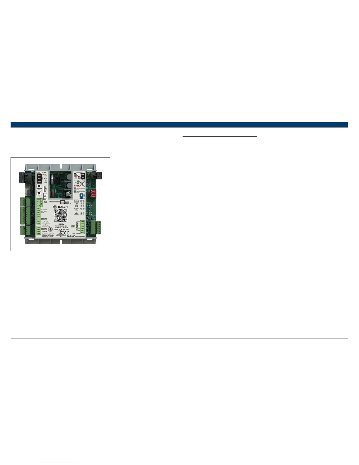
2 FHP560 Overview
The FHP560 Multi-Protocol Heat Pump controller is used in most confi gure-to-order applications requiring integration of Direct Digital Control
(DDC) systems. The controller is BACnet native but is fl exible enough to integrate into existing Building Automation Systems (BAS) via a choice of
the most widely used protocols including: BACnet MS/TP, N2, Modbus, and LON (requires additional hardware). The FHP560 may be run either in
stand-alone operation mode, or with the DDC network by integrating with a BAS.
Fig. 1 FHP560 Controller
The FHP560 is packaged with a highly sophisticated yet easily confi gurable software (version 7.05.03) that suits the different heat pump
applications. User parameters and options relating to the physical build of the corresponding heat pump unit (e.g. number of compressors,
reversing valve, reheat coil, etc) are usually programmed at the factory to facilitate a seamless integration in the fi eld. However, commissioning
of the controller in the fi eld is required to ensure the setup exactly matches the requirements of the jobsite. User settings of the factory standard
software, such as the time and test and balance set points, are usually set up during the installation and commissioning process.
When properly connected to a Bosch Water Source Heat Pump (WSHP), the FHP560 controller works in tandem with the onboard Unit Protection
Module (UPM) to protect the unit compressor from faults such as high/low pressure, high condensate, freeze evaporator/condensor coils, and
brown-outs. The controller monitors the alarm contacts of the UPM board, then decodes and broadcasts any fault conditions that may arise over a
network if one is available.
The controller also works with multi-functional ZS room sensors that, depending on model, are capable of reading not only the zone temperature,
but also CO₂ and relative humidity levels. When wired correctly, the controller commands the heat pump unit to operate in heating or cooling
mode, and can also provide commands for other options such as hot gas reheat to manage relative humidity while cooling. The operating
parameters of the unit may be communicated to a BAS over the DDC network if available.
2.1 Key Features/Benefi ts
Flexible and easily configured software package for options including:
— Hot Gas Reheat
— Auxiliary Electric Heat
— Condenser Water Valve Control
— Loop Pump Control
— Field supplied Fresh Air Damper Control
— Water-Side Economizer
— Boilerless Electric Heat Control
— Air Economizer
Provides multi-protocol communications for seamless integration with systems running industry standard protocols such as:
— BACnet MS/TP
— Johnson Controls N2
— Modbus
— Lon Works (additional hardware required for Lon).
Ruggedly built for quality and reliability
Stand-alone operation or networked DDC operation capable
Removable wiring connectors for ease of field service
Allows application parameters to be saved and recovered following power loss
4
|
FHP560 Controller Applications Manual
Bosch Thermotechnology Corp.
Data subject to change Page____ of ____
3 Specifi cation
Product Specifi cations
Power 24VAC ± 10%, 50-60Hz, 20VA power consumption; Single Class II source only; 100VA or less
Physical Rugged plastic housing protects circuitry
Environmental Operating Range 0° to 130°F (-17.8° to 54.4°C); 10 to 90% relative humidity, non-condensing
Digital Outputs Five (5) binary outputs: Form A relay contacts rated at 1A resistive @ 24VAC; confi gured as dry contact, normally open
Universal Inputs
Six (6) universal inputs. All six inputs are confi gurable for pulse, 10kohm @ 77°F (25°C) thermistor, or dry contact. In addition,
inputs 1 and 2 are confi gurable for 0-5Vdc.
Standard Communication
3-pin port confi gurable for ARC156 (BACnet-over-ARC156) or EIA-485 communications (BACnet MS/TP, Modbus RTU, Lon, or
N2)
Ports
Rnet Port: 4-pin port for interface with remote mounted BACview6 or ZS sensors
Local Access Port: For local communication with a laptop computer running WebCTRL, Virtual BACview, or for communication
with a BACview6.
BACnet Support Advanced Application Controller (B-AAC), as defi ned in BACnet 135-2001 Annex L Communication Ports
Status Indication Visual (LED) status of network communication, run status, errors, power, and all digital outputs
Battery
Lithium 3V coin cell battery, CR2032, provides a minimum of 10,000 hours of data retention (based on installation in
conditioned space) during power outages.
Protection Surge and transient protection circuitry for power and communications
Listed by
FCC Part 15 - Subpart B - Class A. Pending listings at the time of publishing this document: UL 916 (PAZX), cUL C22.2 No. 205M1983 (PAZX7), CE (1997)
Weight 0.6 Lbs. (0.27 Kg).
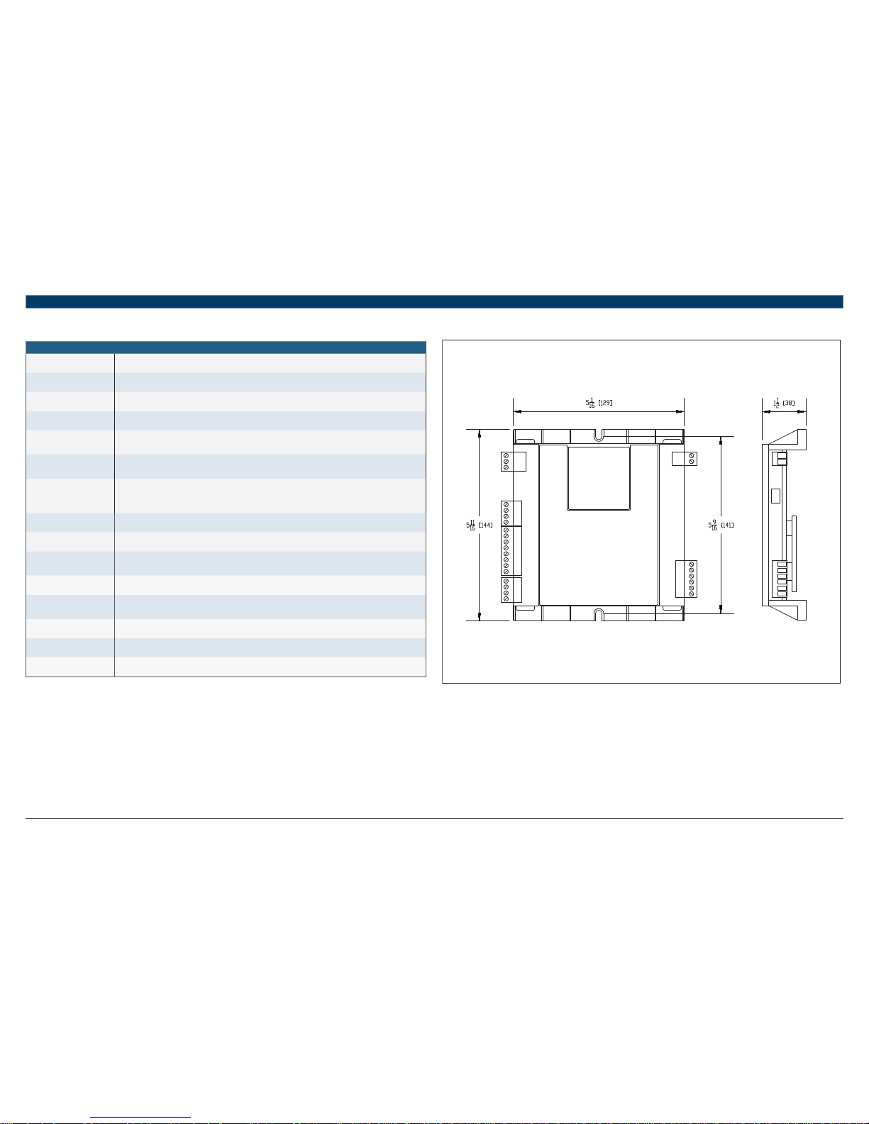
Overall Dimensions
(W x H x D):
5-1/16” (129mm) x 5-11/16” (144mm) x 1-1/2” (38mm) (recommended panel depth)
Mounting Hole Dimensions Two mounting holes located center line of controller with 5-9/16” (141mm) vertical spacing
Table 1
4 Physical Dimensions
Fig. 2 FHP560 Controller Dimensions in Inches (mm)
Applications Manual FHP560 Controller | 5
Bosch Thermotechnology Corp.
Data subject to changePage____ of ____
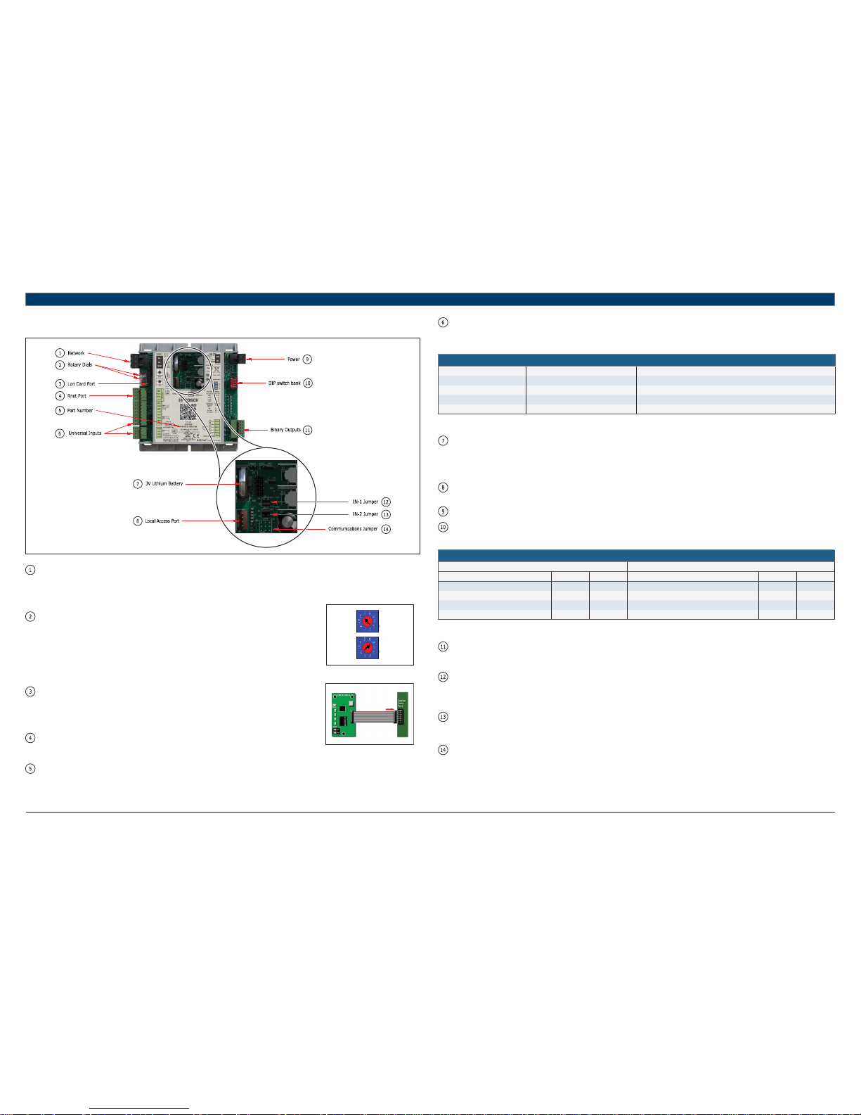
5 Controller Components & Features
Fig. 3 FHP560 Components
Network: This block represents the communications port on the FHP560. The comm port can be confi gured to communicate in two ways
(RS-485 or BACnet over ARC156) using the Communications Jumper. The communications wiring should be landed at the Net+, Net-,
and Shield terminals, ensuring the same polarity is maintained throughout the network segment. The “BAS Port Settings” DIP switch
is used to set the baud rate for the network, using the same baud rate for all controllers on the network. The LEDs (Rx and Tx) fl ash
repeatedly when the controller is communicating with the network.
Rotary Dials: The rotary dials are used to address the FHP560 so it can be uniquely identifi ed over a network.
Ones Tens
The top dial represents the Tens digit while the bottom one represents the Ones digit, allowing
for hardware-based addressing of up to address 99. Before setting or changing the address
make sure the FHP560 is powered off; the controller only reads the address when the module
is turned on. In the example shown in Fig. 4, the rotary dial is set to address 69.
Fig. 4 Rotary Dials
Lon Port: For network integration applications involving the LonWorks network platform, the LON card
will be required to enable communication over this protocol. The card is ordered separately
and connects to the controller port as shown. Ensure that the communications jumper is in the
top position (EIA-485) and the BAS port settings are confi gured using the DIP switch bank
(see DIP Switch).
Rnet Port: The Rnet port is a four-connector block used mainly for wiring the ZS combo sensors to
the FHP560. It consists of 2 points for power (12VDC, Gnd) and 2 points for communication
(Rnet + and Rnet -). This port may also be used to hardwire a BACview6 module.
Fig. 5 Lon Connection
Part Number: The FHP560 part number represents both the hardware and software components of the FHP560, and therefore changes if the
controller is ordered with a special software other than the standard (7.05.03) version.
Inputs: There are 6 universal inputs on the FHP560. All inputs are capable of accepting thermistor (analog), pulse or dry contact (binary)
signals, but the fi rst 2 inputs (IN-1 and IN-2) are also capable of reading 0-5VDC signals; use the corresponding jumpers to select
between Therm/dry and 0-5V for these inputs. Refer to the “Ports Assignment and Overview” page for further details on confi guring
these inputs.
Inputs
Input Signal Type Supported Description
IN-1 and IN-2 0-5Vdc Input impedance of the FHP560 is approx. 30-kOhm
All Thermistor Precon type 2 (10-kOhm @ 77°F/25°C)
All Dry Contact 3.3Vdc wetting voltage detects contact position
All Pulse Pulse counting up to 10 pulses per second.
Table 2
Battery: The 10-year Lithium CR2032 3V battery retains data (e.g. control programs, modifi ed parameters, schedules, etc) for a
maximum of 10,000 hours during power outages. If the FHP560 experiences RAM loss (e.g. due to low voltage on the controller
or high voltage on the network), it may be reset by recycling the battery power. This operation should be performed with the
FHP560 powered off (no 24Vac power), and resolves most of all “bad controller” issues. All previously saved parameters are
retained upon power up.
Local Access: The local access port is available for system start-up, servicing and troubleshooting using a BACview Interface (handheld or
virtual) or Field Assistant.
Power: Input power for the FHP560. 24Vac +/-10%, 50-60Hz; 20VA power consumption, Single Class 2 source only, 100VA or less.
DIP Switch: The BAS Port Settings DIP switch bank is used to set the appropriate network confi guration when the FHP560 is integrated into
a Building Automation System (BAS). The following table details the different settings available (this information is also on the
FHP560 label):
Available Settings
BAUD RATE SETTING PROTOCOL
SW1 SW2 SW3 SW4
9.6kbps Off Off BACnet® MS/TP Off Off
19.2kbps Off On N2 On Off
38.4kbps On Off Modbus Of f On
76.8kbps On On Option Card (LON) On On
Table 3
Outputs: The FHP560 has fi ve (5) binary outputs that can each be connected to a maximum of 24Vac/26Vdc. Each output is a dry contact
(Form A) rated at 1A, 24V max. Refer to the “Ports Assignment and Overview” page for further details on confi guring these
outputs.
IN-1 Jumper: This two-position jumper is used to set the input type selection for IN-1 as follows:
— Top position is labeled W4 and configures IN-1 for dry/therm signals
— Bottom position is labeled W5 and configures IN-1 for 0-5V signals
The jumper is default to the bottom position (W5) for 0-5V from factory.
IN-2 Jumper: This two-position jumper is used to set the input type selection for IN-2 as follows:
— Top position is labeled W6 and configures IN-2 for dry/therm signals
— Bottom position is labeled W7 and configures IN-2 for 0-5V signals
The jumper is default to the top position (W6) for Dry/Therm from factory.
Com Jumper: This two-position jumper is used to confi gure the network communication mode for the FHP560 as follows:
— Top position is labeled EIA-485 and configures the FHP560 for RS-485 communications for BACnet MS/TP, N2, ModBus, or
Lon.
— Bottom position is labeled BACnet over ARC156 and configures the FHP560 for BACnet over ARC156 at 156kbps. This
selection is a unique implementation of the industry standard ARCNET protocol and the jumper should only be set to this
position if employing that protocol.
The jumper is default to the top position (EIA-485) from factory.

6
|
FHP560 Controller Applications Manual
Bosch Thermotechnology Corp.
Data subject to change Page____ of ____
6 Explanation Of DDC Options
AUXILIARY ELECTRIC HEAT:
Used to provide a single stage of electric heat by way of a factory-installed electric heater option, or fi eld-installed electric heater accessory. It may
be used as a supplementary source of heating for units with mechanical heating/cooling capabilities where additional heating capacity is needed
to maintain space setpoint; or as the sole source of heat for straight cool units (mechanical cooling only). The confi gured controller output is
energized to enable the heater based on unit confi guration and parameter setup.
BOILERLESS CONTROL:
An option that allows a water source heat pump to be operated in heating safely when installed in a system that has no means of heating the water
loop. A factory installed Entering Water Temperature (EWT) sensor (thermistor) is connected to the FHP560 controller and used with this option.
During a thermostat call for heating, if the EWT sensor detects a drop in water temperature below a pre-set limit (adjustable in the software), the
FHP560 will disengage the compressor output(s) and provide a 24VAC signal to divert unit operation from compressor heating to an alternate heat
source (generally fi eld-installed electric heat). The option is also used to proactively prevent coils from freezing.
FAN PROVING:
This option uses an optional factory-installed current sensor to prove fan operation prior to unit operation. The status output of the current sensor
is used to establish fan operation for the unit when a proven fan call is established. If confi gured the FHP560 disables unit compressor operation
when the current in the monitored conductor drops below the rated threshold, indicating the fan is non-operational. The current sensor output
may be wired directly to the FHP560, or to an Input Expansion Module (IEM) connected to the FHP560 when multiple options requiring switched
inputs are involved. Please consult the applications department when including this option as an engineering add-on.
FLOW PROVING (DPS):
This option employs the use of an optional Differential Pressure Switch (DPS) to prove water fl ow across a unit’s water-to-refrigerant heat
exchanger. If confi gured the software enables unit compressor operation when a pressure drop of 1.5 psi or more is detected across the water
to refrigerant heat exchanger, indicating adequate water fl ow. This option prevents nuisance cut outs on high head pressure or freeze protection
when there are interruptions in water fl ow.
LOOP WATER VALVE CONTROL:
This option uses an optional factory-installed condenser water valve to control water fl ow through the condenser coil. The normally closed valve
includes an auxiliary end switch that may be wired to the controller to determine the status of the valve. When the FHP560 is confi gured for this
option, compressor operation is disabled until valve-open status from the Valve End Switch is verifi ed.
HOT GAS REHEAT (ON/OFF):
Hot gas reheat helps actively control humidity by reheating cooled and dehumidifi ed air back to a neutral temperature using waste heat from the
compressor. Doing this allows the unit to continue to operate and remove moisture from the space after the sensible cooling set point has been
satisfi ed. Hot gas reheat is well suited for conditioning outside ventilation air and for maintaining ideal humidity levels in schools, commercial
buildings and even homes. A binary output on the FHP560 controller is used to provide the signal for activating the reheat valve when the
necessary conditions are met. Relative humidity readings may be acquired from a wall-mounted ZS combo sensor, a third-party hardwired 0-5V
humidity sensor, or from RH values pushed to the FHP560 over a network.
INPUT EXPANSION MODULE (IEM):
The IEM is used when multiple options that require a binary input are desired for a single application with DDC. The IEM is connected in input
#5 (IN-5) of the FHP560 controller and is software confi gured to enable a trio of preset combinations that include: Fan Status, Valve Status,
Damper Status, Pump Status, Filter Status, Secondary Drain Pan Status, Differential Pressure Switch Status, and Smoke/Fire Detector Status. The
appropriate switches (binary inputs) must be fi eld installed where applicable.
LOOP PUMP CONTROL:
The Loop Pump option uses the FHP560 and a factory installed current sensor to control and monitor a fi eld or factory installed loop pump for
the WSHP units. The pump is indexed to turn on by the controller whenever there’s a call for heating or cooling. The status output of the current
sensor may be used to establish pump operation for the unit when a proven pump call is established. The FHP560 is confi gured to disable unit
compressor operation when the current in the pump’s monitored conductor drops below the rated threshold, indicating pump is not operational.
The current sensor output may be wired directly to the FHP560, or to an Input Expansion Module (IEM) connected to the FHP560 when multiple
options requiring switched inputs are involved. Please consult the applications department when including this option as an engineering add-on.
OUTSIDE AIR DAMPER:
Allows the capability for pre-fi ltered outside air to enter the unit while in operation via a remote motorized damper, based on unit occupancy, fan
operation, or CO₂ levels in the monitored space. A binary output on the FHP560 controller is used to provide the signal for activating the damper
solenoid when the necessary conditions are met. CO₂ readings may be acquired from a wall-mounted ZS combo sensor, a third-party hardwired
0-5V CO₂ sensor, or from CO₂ values pushed to the FHP560 over a network. A damper end switch connected to the FHP560 may be used to verify
damper status and disable compressor operation when the damper fails.
WATER SIDE ECONOMIZER:
An option package consisting of a water-to-air heat exchanger (economizer coil), a thermistor (EWT sensor), and a 3-way diverting valve. When
there is a call for cooling, the EWT sensor connected to the FHP560 will monitor the entering water temperature to the unit and determine if the
compressor should be used for cooling or if the water temperature is low enough to cool the entering air with the economizer coil. If the entering
water temperature is below a selected user-adjustable setpoint, the diverting valve will be indexed by the FHP560 to divert the entering water
through the economizer coil to cool the air stream. The water is then passed through the water to refrigerant coil in case additional cooling is
required. This DDC option can only be used for cooling operations.
AIR ECONOMIZER:
This option utilizes a fi eld-installed fresh air damper, and requires an outdoor air temperature and humidity combo sensor. When there’s a call
for cooling, the OAT/RH sensor connected to the FHP560 will monitor the outside air temperature and humidity levels and determine if the
compressor should be used for cooling or if the outdoor air is ideal to condition the space with just the fan. If the air temperature and humidity is
within a user-confi gurable range, the damper solenoid will be energized to open by the FHP560, the compressors will be indexed off, and the fan is
used to cool the space. This option is only available in the cooling mode.

Applications Manual FHP560 Controller | 7
Bosch Thermotechnology Corp.
Data subject to changePage____ of ____
7 I/O Port Assignments And Overview
Universal Inputs
Port Inputs Accepted Signal Type Jumper Position Overview
IN-1
Digital Input
Enable
Dry Top (W4)
This input is selected when a dry contact (e.g. room occupancy sensor) is required
to enable the unit, and Digital Input has been selected for Occupancy Command.
Unit is placed in occupied mode upon a percieved contact closure at the input, and
placed in unoccupied mode 10 minutes after the contacts open.
Humidity Sensor 0-5VDC Bottom (W5)
This input is used if RH readings are not desired from a ZS Combo sensor or over
a network. An example would be a duct mounted humidity sensor or third party
humidity sensor with 0-5VDC output.
CO₂ Sensor 0-5VDC Bottom (W5)
This input is used if CO₂ readings are not desired from a ZS Combo sensor or over
a network. An example would be a third party CO₂ sensor with 0-5VDC output.
Static Pressure
Sensor
0-5VDC Bottom (W5) This input is used for applications requiring static pressure readings.
IN-2
Zone Remote
Sensor
Therm Top (W6)
This input is used if zone temperature readings for controlling the unit are not
desired from a ZS Combo sensor or over a network. An example would be a third
party wall or duct mounted sensor. Temperature sensor must be a Type II 10kohm
@ 77°F(25°C) type sensor.
Outdoor Air
Temperature
Sensor
Therm Top (W6) This input is selected if outside air temperature readings are required.
Entering Water
Temperature
Sensor
Therm Top (W6)
This input should be selected for applications where the entering water
temperature needs to be monitored, or used to control options such as Economizer
or Boilerless Electric Heat.
Mixed Air
Temperature
Sensor
Therm Top (W6) This input is selected if mixed air temperature readings are required.
Return Air
Temperature
Sensor
Therm Top (W6)
This input is used if zone temperature readings for controlling the unit are desired
from a temperature probe placed in the return air duct. Temperature sensor must
be a Type II 10kohm @ 77°F(25°C) type sensor.
Digital Input
Enable
Dry Top (W6)
This input is selected when a dry contact (e.g. room occupancy sensor) is required
to enable the unit, and Digital Input has been selected for Occupancy Command.
Unit is placed in occupied mode upon a percieved contact closure at the input, and
placed in unoccupied mode 10 minutes after the contacts open.
Humidity Sensor 0-5VDC Bottom (W7)
This input is used if RH readings are not desired from a ZS Combo sensor or over
a network. An example would be a duct mounted humidity sensor or third party
humidity sensor with 0-5VDC output.
IN-3*
Leaving Water
Temperature
Sensor
Therm n/a
A thermistor is wired to this input from factory to monitor leaving water
temperature at the heat exchanger leaving water pipe. If the water temperature
rises above 135°F or drops below 40°F for more than 5 minutes while the unit
is running, compressor operation is halted and an alarm is generated. These
temperature trip values are user adjustable.
Table 4
* Non-confi gurable, factor y assigned I/O parameter
Universal Inputs
Port Inputs Accepted Signal Type Jumper Position Overview
IN-4* UPM Input Pulse n/a
The Unit Protection Module (UPM) is standard on all FHP heat pumps. The alarm
contacts of the UPM board are wired to the controller at this input from factory
to transmit error pulse codes to the FHP560. These alarm codes are then made
available to view via a BACview interface, ZS Pro Sensor, or over a network if one
is available. Faults include: High Pressure, Low Pressure, High Condensate, Freeze
Stat, and Brown out conditions.
IN-5
Dirty Filter Switch
(DFS)
Dry n/a
Selecting this option for this input provides an alternate means of alerting the end
user of a dirty fi lter condition by way of a contact closure instead of fan runtime
hours. An alarm is generated when FHP560 senses a contact closure at the input.
Entering Water
Temperature
Sensor
(Economizer
Cooling &
Boilerless Electric
Heat)
Therm n/a
This input should be the default location for an EWT sensor when the WaterSide Economizer or Boilerless option is selected. The temperature readings from
this input are used in determining when the economizer or electric heat action
is enabled and MUST be selected for the option to function properly. Default
economizer EWT trip value is 55°F (user adjustable). Default boilerless EH EWT trip
value is 40°F (user adjustable).
Differential
Pressure Switch
(DPS)
Dry n/a
A Differential Pressure Switch may be connected to this input to prove water
fl ow across a unit's water-to-refrigerant heat exchanger. Heat pump operation is
disabled until the status switch of the DPS is closed, after which if the contacts
open again unit operation is ceased after 3 minutes.
Secondary Drain
Pan (SDP)
Dry n/a
This option allows a secondary condensate pan installed on the heat pump to be
connected to this input to monitor condensate levels when the primary drain pan
fails. When a high condensate condition for the secondary drain pan is detected an
open contact status is reported at the input, and the compressors are locked out
until the condition is reversed. An alarm is generated when the FHP560 senses an
open contact at the input.
Fan Status Switch
(FSS)
Dry n/a
The status output from a factory installed current sensor used to monitor fan
operation may be connected to this input to provide fan status during unit
operation. The unit is allowed to run only when the sensor contacts are verifi ed
as closed at the input after the fan has been indexed to run. If there's no contact
closure after the fan has been commanded on, the unit is not allowed to run, and
an alarm is generated after 45 seconds. If the fan fails during normal unit operation
the compressors are shutdown after 20 seconds and an alarm is generated.
Valve End Switch
(VES)
Dry n/a
For units with a loop valve option, the Valve End Switch may be connected to this
input to monitor/verify valve status during unit operation. The factory-installed zone
valve is normally-closed and is indexed to open by the FHP560 when there's a call
for heating or cooling. If a contact closure is not detected at the input after the
valve is commanded on, unit operation is disabled and an alarm is generated after a
minute and a half has elapsed; this provides adequate time for the slow acting valve
to fully open.
Damper End
Switch (DES)
Dry n/a
A damper end switch may be connected at this input for units with the outside air
damper option. If connected, the unit is not allowed to run until a contact closure
is detected at the input after the damper has been indexed to open. Damper
operation may be based on occupancy, fan operation, or zone CO₂ levels (default
trip value is 1000ppm).
Table 5
* Non-confi gurable, factor y assigned I/O parameter
8
|
FHP560 Controller Applications Manual
Bosch Thermotechnology Corp.
Data subject to change Page____ of ____
Universal Inputs
Port Inputs Accepted Signal Type Jumper Position Overview
IN-5
Smoke Detector
Switch (SDS)
Dry n/a
The normally-open contacts of a fi eld-installed smoke/fi re alarm detector may be
wired to this input to shut the heat pump unit down during an emergency. Unit
operation is ceased 5 seconds after a contact closure is detected at the input.
Pump Status
Switch (PSS)
Dry n/a
For units with a loop pump option, the status output from a factory installed
current sensor used to monitor pump operation may be connected to this input to
provide pump status during unit operation. The unit is allowed to run only when the
sensor contacts are verifi ed as closed at the input after the pump has been indexed
to run. If there's no contact closure after the loop pump has been commanded on,
the unit is not allowed to run, and an alarm is generated after 15 seconds. If the
pump fails during normal unit operation the compressors are shutdown after 20
seconds and an alarm is generated.
Mixed Air
Temperature
Sensor
Therm n/a
Select this confi guration parameter if a Mixed Air Temperature sensor is connected
in IN-5.
Input Expansion
Module (IEM)
Dry n/a
The Input Expansion Module is used in this input when multiple options that
require a binary input are required (up to 3 inputs). The combinations of these
options are limited only to the seven (7) sets of three listed below.
Input Expansion Module (IEM) Combination
These seven (7) sets of binary input combinations may be used with an IEM
connected to this input. The three (3) ports are labled (A, B, C) and must be
connected correspondingly. In situations where not all three inputs are used, the
other inputs may be disabled in the software, or the board may be jumpered if the
option requires a closed contact to function properly.
PORT 1 (A) PORT 2 (B) PORT 3 (C)
Dirty Filter Switch
(DFS)
Fan Status Switch
(FSS)
Valve End Switch
(VES)
Smoke Detector
Switch (SDS)
Fan Status Switch
(FSS)
Valve End Switch
(VES)
Dirty Filter Switch
(DFS)
Fan Status Switch
(FSS)
Differential
Pressure Switch
(DPS)
Smoke Detector
Switch (SDS)
Fan Status Switch
(FSS)
Dirty Filter Switch
(DFS)
Dirty Filter Switch
(DFS)
Fan Status Switch
(FSS)
Damper End
Switch (DES)
Smoke Detector
Switch (SDS)
Fan Status Switch
(FSS)
Secondary Drain
Pan (SDP)
Dirty Filter Switch
(DFS)
Fan Status Switch
(FSS)
Pump Status
Switch (PSS)
IN-6*
Discharge Air
Temperature
Therm n/a
A factory-installed thermistor mounted on the heat pump unit's blower housing
(air handler section) is connected to this input for all orders requiring the factory
installed DDC option. It is highly recommended that for applications requiring
a more accurate representation of the supply air temperature, a duct mounted
temperature probe be used instead to relocate the source of the discharge air
temperature just downstream of the supply air duct. If this recommendation is
followed the factory-installed thermistor may be disconnected from this input, and
replaced with the leads from the duct mounted sensor.
Table 6
* Non-confi gurable, factor y assigned I/O parameter
Binary Outputs
Port Outputs Accepted Signal Type Signal Label Overview
BO-1* Fan 24VAC G
Binary Output 1 is factory reserved for the fan command (G) and is wired to the
unit terminal block in the electrical box. The fan mode may be software confi gured
either for "continuous" mode (fan is energized continuously during occupied and
night set back modes), or confi gured to run in "auto" mode (fan is energized only
during a call for heating or cooling). Continuous mode is the factory default setting.
BO-2* Reversing Valve 24VAC O
Binary Output 2 is factory reserved for the reversing valve command (O) and is
wired to the valve via the unit terminal block in the electrical box. For heat pump
units, the output is energized during a call for cooling, and remains de-energized
for heating. For straight cool units (cooling only) where no reversing valve is
installed, the output is disabled and not used.
BO-3*
Compressor
Stage 1
24VAC Y1
Binary Output 3 is factory reserved for the compressor stage 1 command (Y1) and
is connected to the UPM I board's "Y" terminal ("Y1" for dual compressor units
using the UPM II board) via the unit terminal block in the electrical box. The Y1
output is off when zone setpoint is satisfi ed and within the temperature deadband
(between heating and cooling setpoints). As the zone temperature rises above
the cooling setpoint and demand exceeds 30%, Y1 is enabled and PID methods
are employed to ensure the zone temperature is maintained within 1°F of cooling
setpoint. As the zone temperature drops below the heating setpoint and demand
exceeds 30%, Y1 is enabled and PID methods are employed to ensure the zone
temperature is maintained within 1°F of heating setpoint.
BO-4
Compressor
Stage 2
24VAC Y2
Binary Output 4 is factory defaulted for the compressor stage 2 command (Y2) and
is connected to the second stage solenoid (Y2S) for 2-step, single compressors,
or to the “Y2” terminal for dual compressor units using the UPM II board, via the
unit terminal block in the electrical box. The Y2 output is off when zone setpoint
is satisfi ed and within the temperature deadband (between heating and cooling
setpoints). The Y2 output is energized after Y1 has been on for more than 7
minutes, and the heating/cooling demand exceeds 60%.
For 1 compressor 1 stage units, Binary Output 4 may be confi gured for one of the
following options: Hot Gas Reheat (On/Off), Single Stage Auxiliary Electric Heat, or
Outside Air Damper (On/Off).
Hot Gas Re-Heat
(On/Off)
24VAC H
Fresh Air Damper
(On/Off)
24VAC D
Heating Stage 1
(Aux Heat)
24VAC W
BO-5
Hot Gas Re-Heat
(On/Off)
24VAC H
Binary Output 5 may be factory or fi eld confi gured for one of the following
options: Hot Gas Reheat (On/Off), Single Stage Auxiliary Electric Heat, Outside Air
Damper (On/Off), Condenser Water Valve, Circulating Water Pump, Economizer, or
Boilerless Electric Heat.
Fresh Air Damper
(On/Off)
24VAC D
Heating Stage 1
(Aux Heat)
24VAC W
Boilerless Control
(Aux Heat)
24VAC W
Economizer
Cooling Control
24VAC EV
Circulation Water
(Loop) Pump
24VAC P
Condenser Water
Valve
24VAC CV
Table 7
* Non-confi gurable, factor y assigned I/O parameter
All I/Os must be selected/confi gured in the software or
over a BAS network.
Applications Manual FHP560 Controller | 9
Bosch Thermotechnology Corp.
Data subject to changePage____ of ____
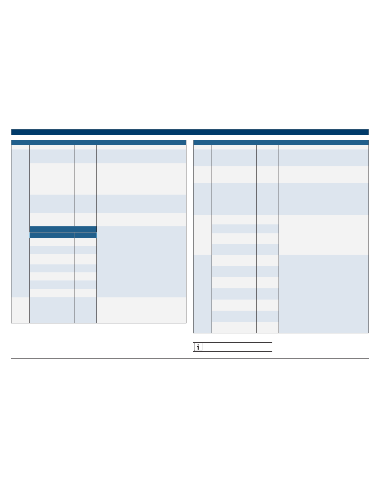
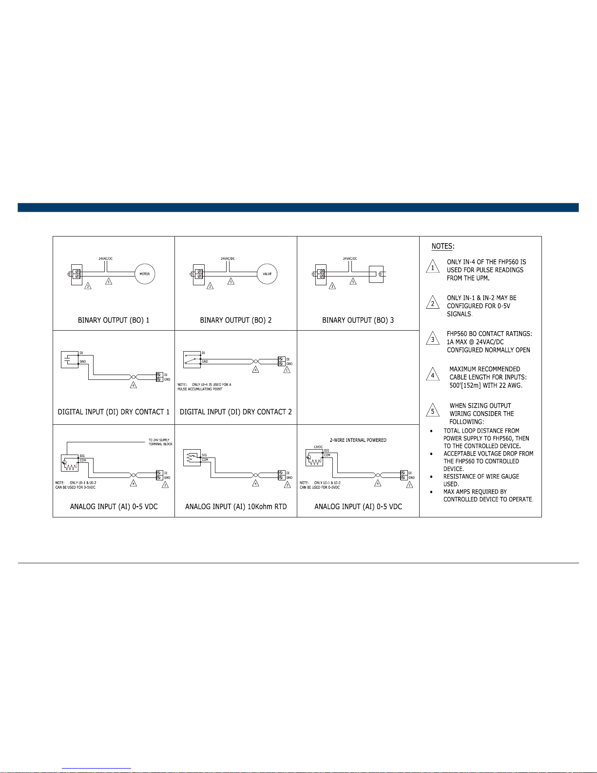
8 Wiring Termination Specs
10
|
FHP560 Controller Applications Manual
Bosch Thermotechnology Corp.
Data subject to change Page____ of ____
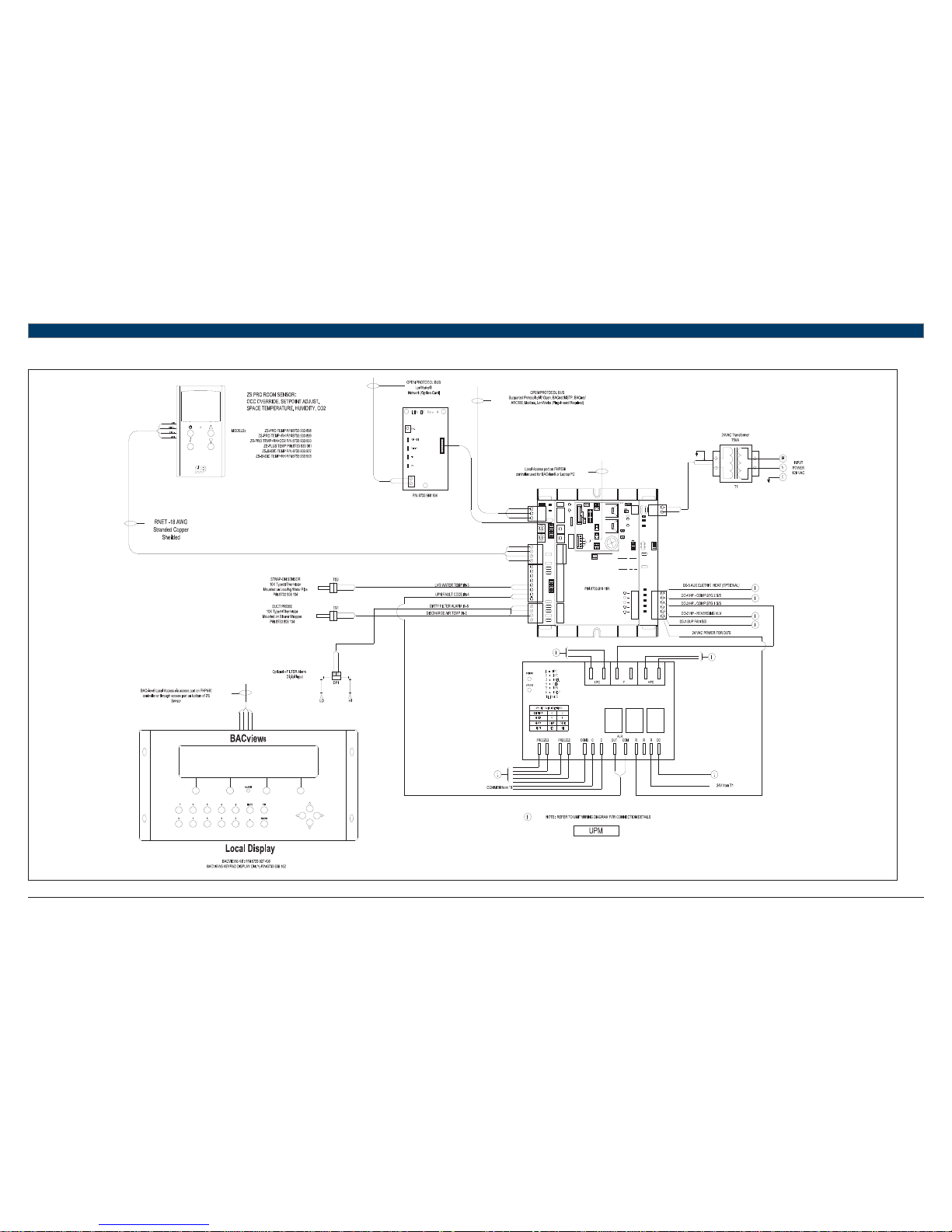
9 Electrical Schematic
Power forB.O.'s
BACnet
5
6
7
8
9
0
1
2
3
4
5
6
7
8
9
0
1
2
3
4
Rx
Tx
BT485
Net +
Net -
Shield
Comm
10's1's
Batt
+
-
CR
2032
Rnet +
Inputs 1 & 2
0-5V, therm,
or dry
®
24 Vac
FHP560
Thermistor/dry
contact
0-5Vdc
Thermistor/dry
contact
0-5Vdc
1 2 3 4
ON
On
Communications Selection
4
3
2
1
EIA-485
BACnet
Over ARC156
Lstat
IN-5
Format
Short
pins
Rnet
Outputs
24V
Max,
1A Max
Inputs 3
& 4
Therm or
dry
Inputs 5 & 6
Therm or dry
Comm
Selector
DIP Switch
BAUD RATES
SW1 SW2
PROTOCOLS SW3 SW4
9600
19.2 K
38.4 K
76.8 K
Off
On
Off
On
BACnet
MS/TP
N2
Modbus Off On
Local
Access
Sense
+12V
Rnet-
Rnet+
Gnd
Gnd
Rnet +
Rnet -
+12V
IN-1
Gnd
IN-2
Gnd
IN-3
Gnd
IN-4
Gnd
Gnd
IN-5
IN-6
LED
BO-3
BO-2
BO-1
BUS
BO-4
BO-5
Gnd
Hot
Power
Run
Error
IN-1
IN-2
BO5
BO4
BO3
BO2
BO1
POWER
RUN
ERROR
RXD
TXD
Off
Off
On
On
OffOff
OffOn
Option Card
On On
UNIT PROTECTI ON MODULE
FHP P/N 8733 809 536
Applications Manual FHP560 Controller | 11
Bosch Thermotechnology Corp.
Data subject to changePage____ of ____
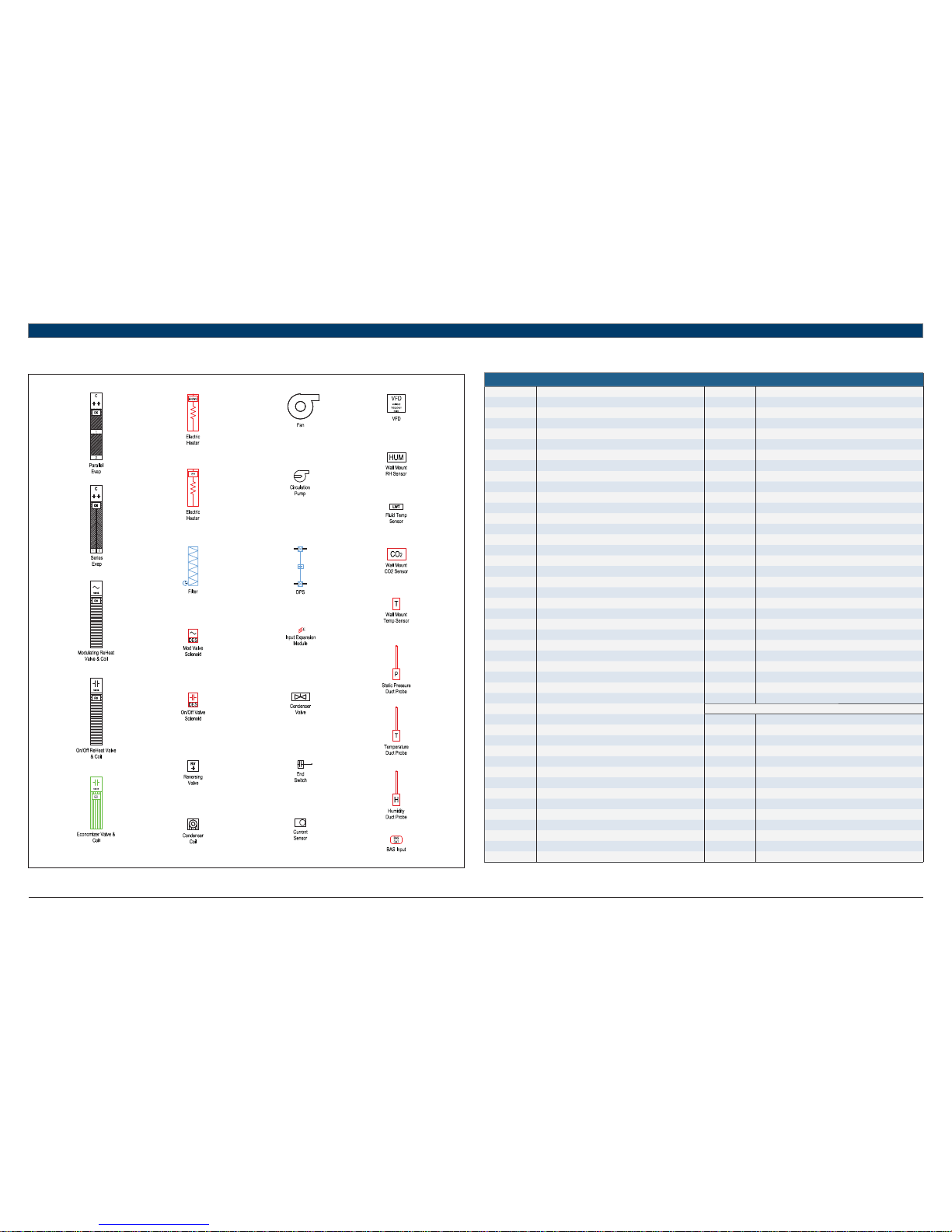
10 Symbol Legend
10.1 Common Abbreviations
Abbreviations
AFMS Air Flow Measuring Station MOD Modulating
AC Air Conditioning NC Normally Closed
ACU Air Conditioning Unit NO Normally Open
AHU Air Handling Unit OA Outdoor Air
AI Analog Input OAD Outdoor Air Damper
AO Analog Output OCC Occupancy
AUTO Automatic RA Return Air
AUX Auxiliary RF Return Fan
BAS Building Automation System RH Relative Humidity
BC Boilerless Control RV Reversing Valve
BI Binary Input SA Supply Air
BMS Building Management System SCR Silicon-Controlled Rectifi er
BO Binary Output SDP Secondar y Drain Pan
C Common (24VAC) SDS Smoke Detector Switch
CHW Chilled Water SECS Seconds
COND Condenser SF Supply Fan
COMP Compressor SOO Sequence of Operation
CW Condenser Water SP Static Pressure
CWP Circulating Water Pump S/S Start/Stop
DA Discharge Air STG Stage
DDC Direct Digital Control TEMP Temperature
DES Damper End Switch UI Universal Input
DFS Dirty Filter Switch UPM Unit Protection Module
DI Digital Input VAV Variable Air Volume
DO Digital Output VES Valve End Switch
DPS Differential Pressure Switch VFD Variable Frequency Drive
DX Direct Expansion VLV Valve
EA Exhaust Air WSE Water-Side Economizer
EF Exhaust Fan WSHP Water Source Heat Pump
EVAP Evaporator
EW Entering Water THERMOSTAT SIGNALS
F Fahrenheit G Fan Signal
FM Flow Meter O Reversing Valve Signal
FSS Fan Status Switch Y1 Compressor Stage 1 Signal
HGRH Hot Gas Re-Heat Y2 Compressor Stage 2 Signal
HP Heat Pump/High Pressure W Electric Heat Signal
HW Hot Water H Reheat Signal
IEM Input Expansion Module EV Economizer Valve Signal
LP Loop Pump/Low Pressure CV Condenser Valve Signal
LW Leaving Water P Pump Signal
MA Mixed Air
MAX Maximum
MIN Minimum
MINS Minutes
MISC Miscellaneous
Table 8
12
|
FHP560 Controller Applications Manual
Bosch Thermotechnology Corp.
Data subject to change Page____ of ____
11 Common Applications
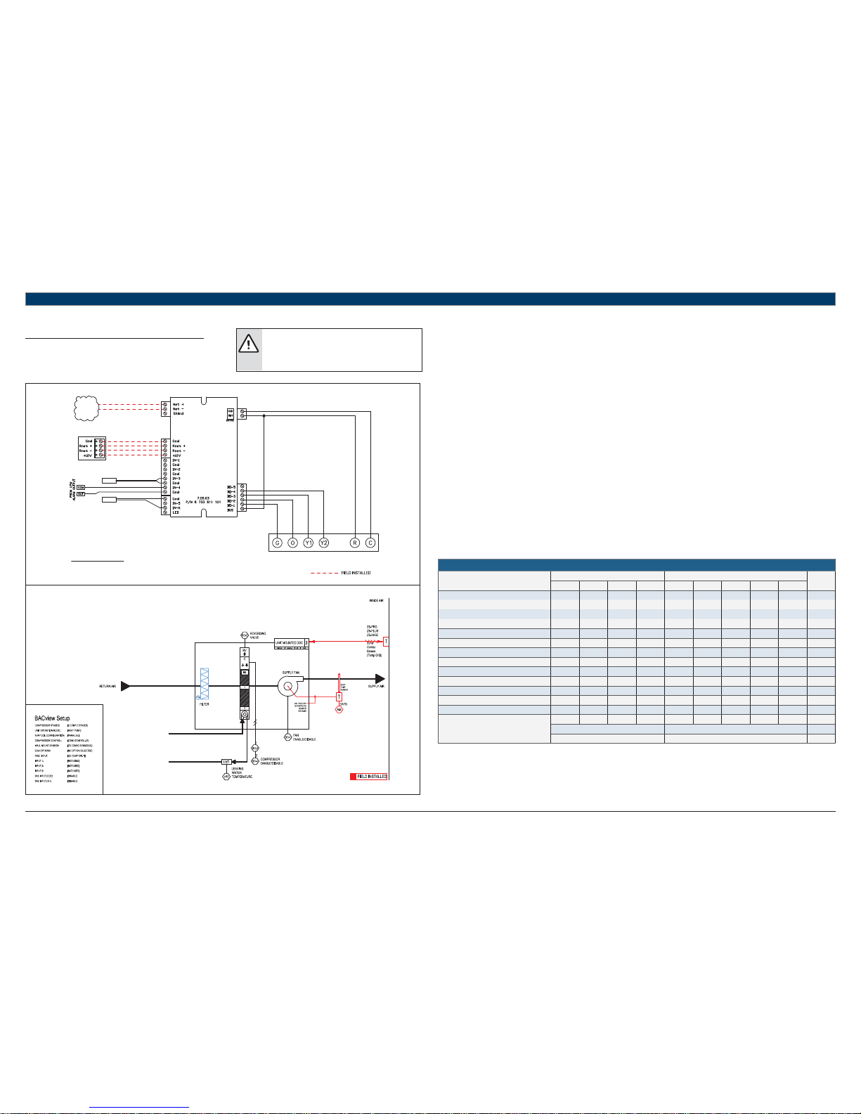
11.1 HP Basic
UNIT TERMINAL BLOCK
TO BACnet
MS/TP
NETWORK
LWTS
DATS
RED
GREEN
WHITE
BLACK
TERMINATION DETAIL
RNET: SENSORS
ZS COMBO SENSOR (TEMP ONLY)
STANDARD COMPONENTS:
DATS - DISCHARGE AIR TEMPERATURE SENSOR
LWTS - LEAVING WATER TEMPERATURE SENSOR
REFER TO UNIT WIRING DIAGRAM FOR FURTHER DETAILS
FHP560
Heat Pump Sequence of Operation – HP Basic
Supply Fan Start/Stop:
The supply fan will be started according to the schedule. After the supply fan has been started the control sequence will be enabled. Fan
operation is interlocked with heating and cooling operations. The fan may be confi gured for continuous operation during occupancy or for
operation based on heat/cool calls.
Zone Control:
The compressor will cycle to maintain the zone temperature at setpoint. To prevent short cycling there will be a 5 minute delay between
compressor stages. Additionally there’ll be a 1-minute delay when transitioning between heat and cool modes. The compressor will run subject to
internal safeties and controls provided by the upm.
Zone temperature may be supplied by a space ZS sensor, remote mounted sensor, or from a network value. All setpoints are adjustable via a
network, space ZS sensor Pro or plus, or with the BACview terminal. The ability to adjust setpoint from the space sensor, and the adjustment limit
(default +/-3 degress f) may be modifi ed via a network or BACview.
Heat Pump Control:
When the zone temperature falls below the zone temperature setpoint the reversing valve(s) will be disabled to provide heating when the
compressor is running. When the zone temperature rises above the zone temperature setpoint the reversing valve will be enabled to provide
cooling when the compressor is running.
A networked “loop valve enable” point must be enabled to allow compressor operation. This point is defaulted “on” from factory.
Night Setback:
When in “unoccupied”, the unit will cycle as necessary to maintain the night setback zone temperature at setpoint. A differential prevents the unit
from cycling excessively. During unoccupied operation the fan will only cycle to maintain a heat or cool setpoint.
Shutdown:
When the unit is shutdown by either a stop command or system safety the unit will be set as follows:
Supply fan will be on (user configurable)
Compressor(s) will be off
HEAT PUMP
Point Name
Hardware Points Software Points
Show On
Graphic
AI AO BI BO AV BV Sched Trend Alarm
Zone Temperature X X X X
Heating Setpoint X
Cooling Setpoint X
Supply Fan Command X
Compressor Stage 1 Output X
Compressor Stage 2 Output X
Reversing Valve Command X
Occupied Command X X X X
Discharge Air Temperature X
Leaving Water Temperature X
Condensate Overfl ow X
Lockout Alarm X
Schedule
Totals
3014311122
Total Hardware Total Software
882
Table 9
WARNING:
These diagrams are for reference purposes only. Please
refer to the actual unit wiring diagram for specifi c details
on how to wire your heat pump unit.
Applications Manual FHP560 Controller | 13
Bosch Thermotechnology Corp.
Data subject to changePage____ of ____
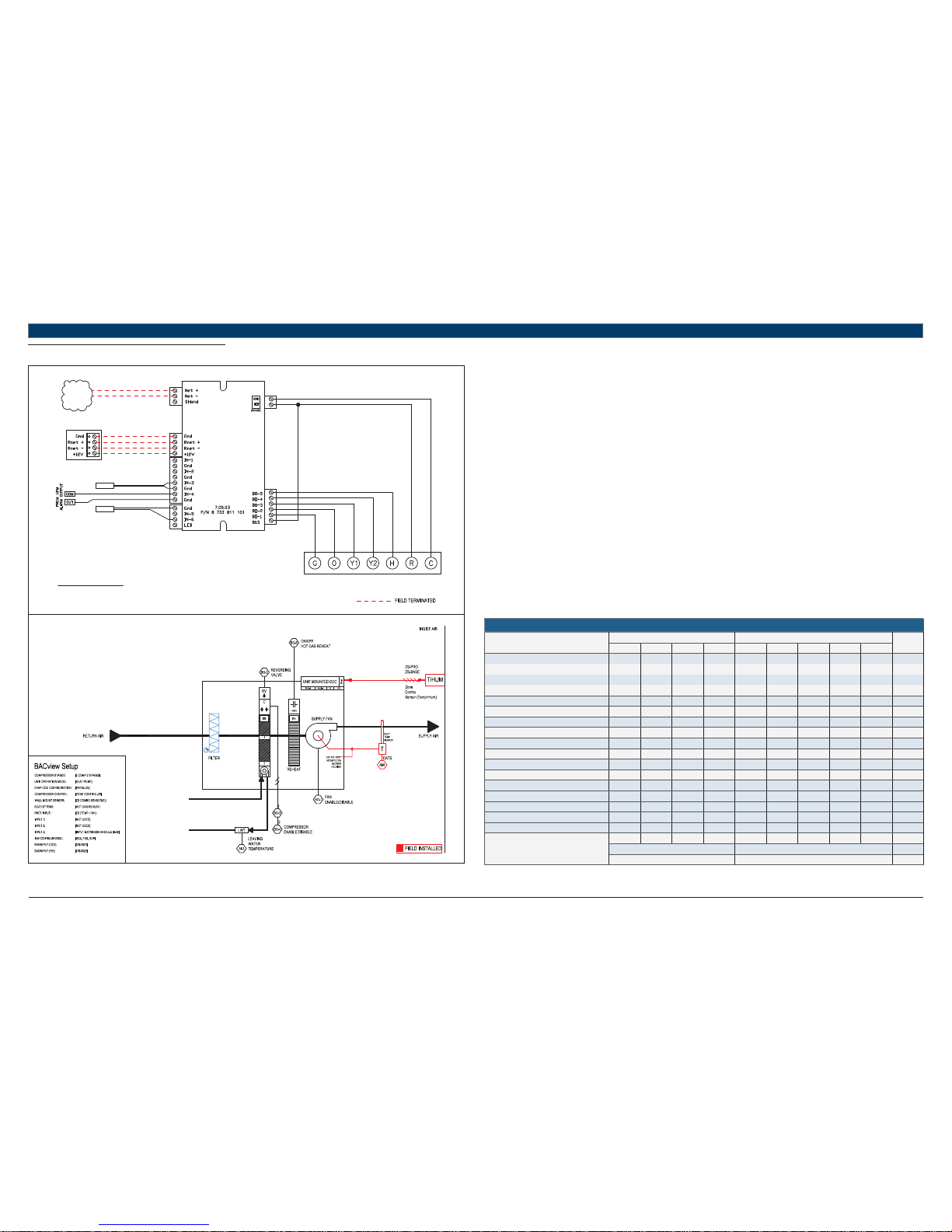
11.2 HP + HGRH
UNIT TERMINAL BLOCK
TO BACnet
MS/TP
NETWORK
LWTS
DATS
RED
GREEN
WHITE
BLACK
TERMINATION DETAIL
RNET: SENSORS
ZONE COMBO SENSOR (TEMP+RH)
STANDARD COMPONENTS:
DATS - DISCHARGE AIR TEMPERATURE SENSOR
LWTS - LEAVING WATER TEMPERATURE SENSOR
REFER TO UNIT WIRING DIAGRAM FOR FURTHER DETAILS
FHP560
Heat Pump Sequence of Operation – HP + HGRH
Supply Fan Start/Stop:
The supply fan will be started according to the schedule. After the supply fan has been started the control sequence will be enabled.
Zone Control:
The compressor will cycle to maintain the zone temperature at setpoint.
Heat Pump Control:
When the zone temperature falls below the zone temperature setpoint the reversing valve(s) will be disabled to provide heating when the
compressor is running. When the zone temperature rises above the zone temperature setpoint the reversing valve will be enabled to provide
cooling when the compressor is running.
Night Setback:
When in “unoccupied”, the unit will cycle as necessary to maintain the night setback zone temperature at setpoint. A differential prevents the unit
from cycling excessively.
Shutdown:
When the unit is shutdown by either a stop command or system safety the unit will be set as follows:
Supply fan will be on (user configurable)
Compressor(s) will be off
Hot Gas Reheat:
Once the heat/cool setpoint has been satisfi ed and relative humidity is above setpoint, the unit will operate in hot-gas reheat mode to actively
remove humidity from the space until the the humidity setpoint has been satisfi ed, or there’s another call for heating or cooling.
Relative humidity readings may be acquired from a space ZS combo Pro or standard sensor, 0-5V sensor in IN-1/IN-2, or over a network; software
must be confi gured accordingly.
Humidity setpoint may be adjusted from a space ZS sensor Pro, network, or BACview interface.
HEAT PUMP
Point Name
Hardware Points Software Points
Show On
Graphic
AI AO BI BO AV BV Sched Trend Alarm
Zone Temperature X X X X
Heating Setpoint X
Cooling Setpoint X
Supply Fan Command X
Compressor Stage 1 Output X
Compressor Stage 2 Output X
Reversing Valve Command X
Occupied Command X X X X
Discharge Air Temperature X
Leaving Water Temperature X
Dehumidifi cation Setpoint XX
Reheat Status
Reheat On/Off (Rh S/S) X X
High Return Air Humidity X
Condensate Overfl ow X
Lockout Alarm X
Schedule
Totals
3015411134
Total Hardware Total Software
9104
Table 10
14
|
FHP560 Controller Applications Manual
Bosch Thermotechnology Corp.
Data subject to change Page____ of ____
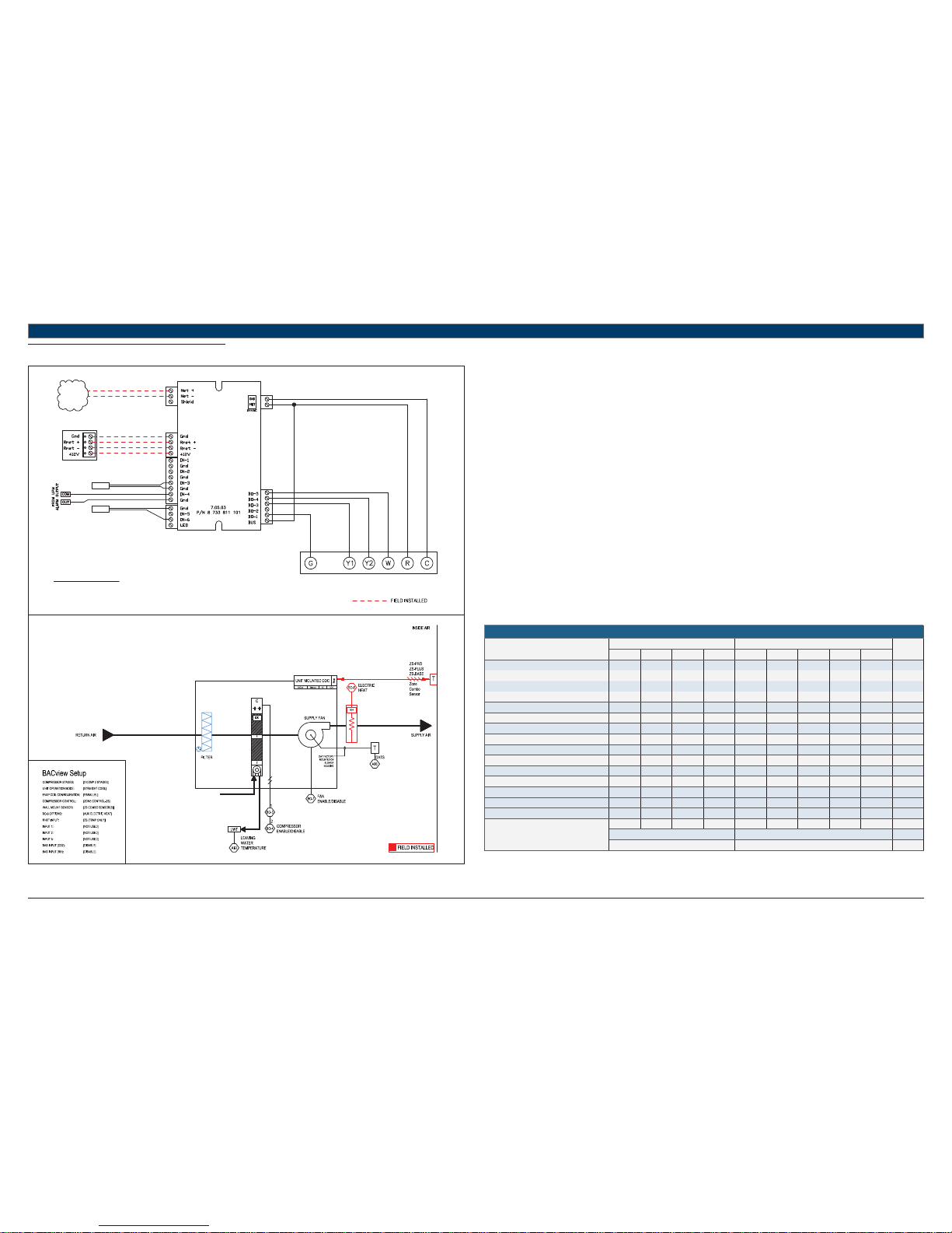
11.3 STRAIGHT COOL + EH
UNIT TERMINAL BLOCK
TO BACnet
MS/TP
NETWORK
LWTS
RED
GREEN
WHITE
BLACK
TERMINATION DETAIL
RNET: SENSORS
STANDARD COMPONENTS:
DATS - DISCHARGE AIR TEMPERATURE SENSOR
LWTS - LEAVING WATER TEMPERATURE SENSOR
REFER TO UNIT WIRING DIAGRAM FOR FURTHER DETAILS
FHP560
DATS
Heat Pump Sequence of Operation – STRAIGHT COOL + EH
Supply Fan Start/Stop:
The supply fan will be started according to the schedule. After the supply fan has been started the control sequence will be enabled.
Zone Control:
The compressor will cycle to maintain the zone temperature at setpoint.
Straight Cool Control:
Unit is confi gured for mechanical cooling only and the reversing valve is not installed. BO-2 is disabled and unused.
Night Setback:
When in “unoccupied”, the unit will cycle as necessary to maintain the night setback zone temperature at setpoint. A differential prevents the unit
from cycling excessively.
Shutdown:
When the unit is shutdown by either a stop command or system safety the unit will be set as follows:
Supply fan will be on (user configurable)
Compressor(s) will be off
Auxiliary electric heat:
Electric Heat (EH) option may be factory or fi eld installed and must be confi gured by the equipment integrator. Only one (1) stage of auxiliary
electric heat is supported and may be confi gured for BO-4 (single stage compressor units) or BO-5 (dual stage compressor units).
Upon a call for heating with demand greater than 90% (user confi gurable), the EH signal will be enabled to maintain setpoint at the confi gured
output as follows:
Straight cool units: enabled with no delay
Single stage heat pump units: enabled 5 mins after first stage of mechanical heat if demand is still above 90%.
Dual stage heat pump units: enabled 5 mins after second stage of mechanical heat if demand is still above 90%.
HEAT PUMP
Point Name
Hardware Points Software Points
Show On
Graphic
AI AO BI BO AV BV Sched Trend Alarm
Zone Temperature X X X X
Heating Setpoint X
Cooling Setpoint X
Supply Fan Command X
Compressor Stage 1 Output X
Compressor Stage 2 Output X
Reversing Valve Command
Occupied Command X X X X
Discharge Air Temperature X
Leaving Water Temperature X
Entering Water Temperature X
Aux Electric Heat Output X
Condensate Overfl ow X
Lockout Alarm X
Schedule
Totals
4014311122
Total Hardware Total Software
982
Table 11
Applications Manual FHP560 Controller | 15
Bosch Thermotechnology Corp.
Data subject to changePage____ of ____
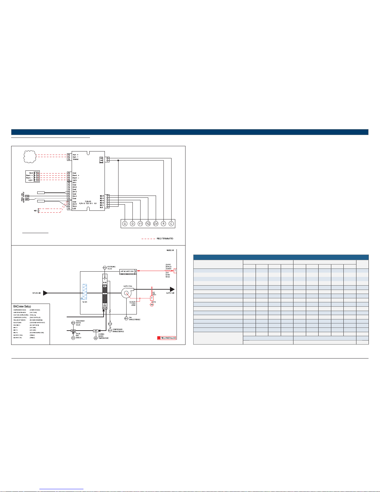
11.4 STRAIGHT HP + CWV
UNIT TERMINAL BLOCK
TO BACnet
MS/TP
NETWORK
LWTS
DATS
RED
GREEN
WHITE
BLACK
TERMINATION DETAIL
RNET: SENSORS
STANDARD COMPONENTS:
DATS - DISCHARGE AIR TEMPERATURE SENSOR
LWTS - LEAVING WATER TEMPERATURE SENSOR
REFER TO UNIT WIRING DIAGRAM FOR FURTHER DETAILS
FHP560
Heat Pump Sequence of Operation – HP + CWV
Supply Fan Start/Stop:
The supply fan will be started according to the schedule. After the supply fan has been started the control sequence will be enabled.
Zone Control:
The compressor will cycle to maintain the zone temperature at setpoint.
Heat Pump Control:
When the zone temperature falls below the zone temperature setpoint the reversing valve will be disabled to provide heating when the
compressor is running. When the zone temperature rises above the zone temperature setpoint the reversing valve will be enabled to provide
cooling when the compressor is running.
Night Setback:
When in “unoccupied”, the unit will cycle as necessary to maintain the night setback zone temperature at setpoint.
Shutdown:
When the unit is shutdown by either a stop command or system safety the unit will be set as follows:
Supply fan will be on (user configurable)
Compressor(s) will be off
Condenser Water Valve:
Factory installed loop valve with Valve End Switch (VES) option must be confi gured by the equipment integrator. Upon a call for compressor
operation the normally closed valve is indexed to open via a 24Vac signal at BO-5. If the VES is confi gured, compressor operation is not enabled
until Valve End Switch is engaged (valve fully open).
Valve open status is verifi ed via the VES within 1.5 Mins of valve enable command.
If VES contacts do not engage within the specifi ed time, VES fail alarm is initiated. If valve opens without command from BO-5, valve in hand alarm
is initiated.
Compressor operation is disabled 20 secs after VES opens (fails) when loop valve has been indexed to open.
HEAT PUMP
Point Name
Hardware Points Software Points
Show On
Graphic
AI AO BI BO AV BV Sched Trend Alarm
Zone Temperature X X X X
Heating Setpoint X
Cooling Setpoint X
Supply Fan Command X
Compressor Stage 1 Output X
Compressor Stage 2 Output X
Reversing Valve Command X
Occupied Command X X X X
Discharge Air Temperature X X
Leaving Water Temperature X X
Loop Valve Command X X
Valve End Switch (Valve Status) X X
Condensate Overfl ow X
Lockout Alarm X
Schedule
Totals
3025531122
Total Hardware Total Software
10 12 2
Table 12
 Loading...