

Page 1
Wireless Smoke Alarm
FERION 5000 OW
en
Page 2

Page 3

Wireless Smoke Alarm Table of Contents | en 3
Table of contents
1
Graphics 4
2
Introduction 6
3
Mounting 7
4
Radio Network 9
5
Maintenance 12
6
Technical data 14
7
Customer Service 16
Bosch Sicherheitssysteme GmbH 08.15 | 2.1 | F.01U.309.850
Page 4
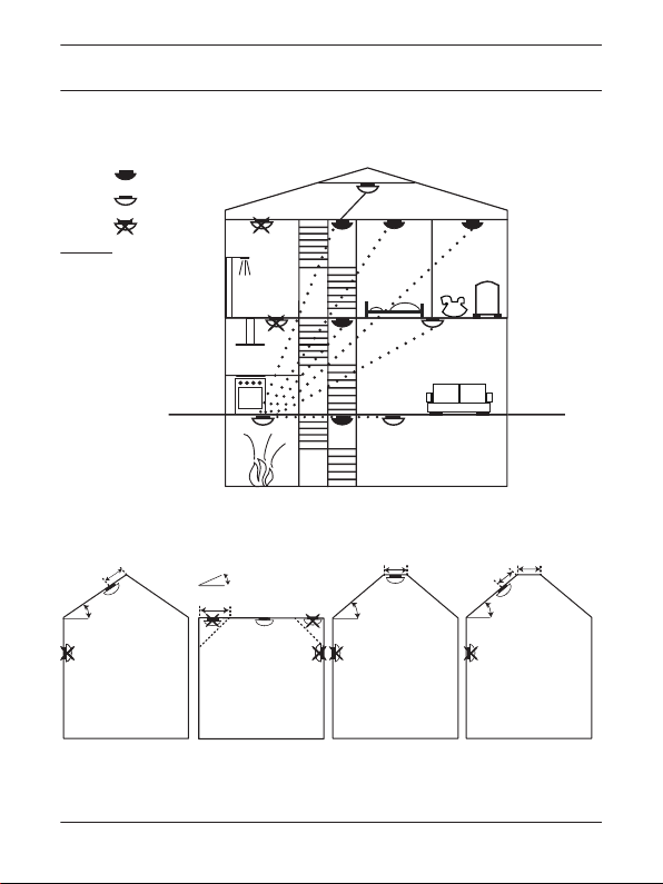
(1)
minimum
additional
unsuitable
R repeater ON
R
>20°
(2. A) (2.B) (2. C) (2. D)
>20°
>1m
≤1m
>20°
0.5-1m
0.5-1m
0.5m
0-20°
4 en | Graphics Wireless Smoke Alarm
1 Graphics
08.15 | 2.1 | F.01U.309.850 Bosch Sicherheitssysteme GmbH
Page 5
A
B
2
1
3
4
2
1
1
60 mm
2
1
1
(5)
B
A
(3)
1 x 3 mm
2 x 3 mm
(4)
< 2 s
(6)
(7)
Wireless Smoke Alarm Graphics | en 5
Bosch Sicherheitssysteme GmbH 08.15 | 2.1 | F.01U.309.850
Page 6
!
6 en | Graphics Wireless Smoke Alarm
2 Introduction
The FERION 5000 OW wireless smoke alarm device with built‑in
long-life battery, built‑in siren (4.1), alarm LED (4.2), emergency
light (4.3) and big button for operation (4.4) is solely designed
for residential applications. The device reliably warns you of the
emergence of a fire in your house or flat. If the smoke emissions
exceed a certain limit, an alarm is raised. More information, CE
declaration, and declaration of performance is available on
www.boschsecurity.com/ferion/.
The safety notes and instructions contained in this manual must
be observed in order to ensure proper function. The device must
not be modified in any way. If you have any questions about the
method of operation, safety or connection of the device, consult
the place of purchase.
Caution!
Only use original parts. Only use installation materials
as recommended in this manual. Do not paint over the
device! Do not cover it with wallpaper! Replacement
after 10 years recommended.
08.15 | 2.1 | F.01U.309.850 Bosch Sicherheitssysteme GmbH
Page 7

Wireless Smoke Alarm Graphics | en 7
Notice!
Do not use if there are signs of damage, or in case of
malfunction. Return defective devices to the place of
purchase.
Not suitable for household room illumination!
Old devices are not to be disposed of with the
household waste. Dispose of them according to the
guidelines for electric and electronic waste at the
local collection points.
Parts included
1 smoke alarm device: base (3.A) and detector head (3.B)
Fastening material: 1 screw, 1 plug
3 Mounting
Notice!
The device is designed for mounting according to DIN
14676 on flat or slanted ceiling. Wall mounting is not
allowed.
Perform the following steps. Find exact information about the
single steps on the following pages in this manual. See also the
graphics at the beginning of this manual.
1. Determination of the mounting locations. (1) Observe the
information regarding Unsuitable locations for mounting, page
8, and regarding Audibility, page 8. Each device is to be
Bosch Sicherheitssysteme GmbH 08.15 | 2.1 | F.01U.309.850
Page 8

en | Graphics Wireless Smoke Alarm
8
mounted horizontally on the ceiling in centered position with
a minimum distance of 0.5m to walls and objects. On slanted
ceilings >20° it is to be mounted 0.5m to 1m from the top of
the ceiling. (2.A), (2.B), (2.C), (2.D)
2. Connecting devices, page 10. For testing the network,
position the devices near to the determined mounting
locations: Testing the network, page 10. If necessary switch
the repeater function on for one device, see Repeater
function, page 11.
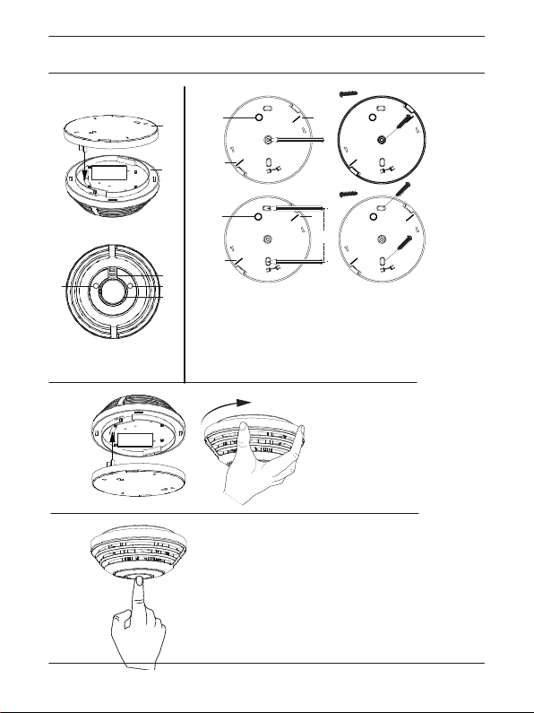
3. For each device: Mounting the base. (5) Observe the mark
(5.2) for adjusting the emergency light and the marks (5.1)
for alignment with BOSCH label/siren.
4. Functional check, page 12, for each device after setting it up
into operation. (6) (7)
Unsuitable locations for mounting
– Kitchen/bathroom (steam)
– Rooms with open fireplaces (fumes)
– In the immediate vicinity of halogen lamps, transformers,
fluorescent or energy-saving lamps
– Garages (exhaust fumes)
– Dusty and dirty rooms
– In the vicinity of windows, ventilators (air movement)
– In the vicinity of areas where people smoke
Audibility
You must hear an alarm at any place in your building or flat. The
alarm really has to wake you up. If necessary adapt the number of
the devices for achieving audibility in your whole building or flat.
08.15 | 2.1 | F.01U.309.850 Bosch Sicherheitssysteme GmbH
Page 9

Wireless Smoke Alarm Graphics | en 9
Mounting the base
Mount the base with one central screw and plug. (5.A) Or
optionally use two screws and plugs. (5.B) To set the device into
operation you screw the detector head to its base by twisting it
clockwise until it latches. (6)
4 Radio Network
Up to 40 FERION 5000 OW can be interconnected to create a
network. Thus, an alarm is raised at all devices giving the chance
to react faster to a distant fire. Before mounting to the ceiling,
position the devices you want to connect next to each other.
Leave a minimum distance of 1 m in between.
Notice!
FERION 5000 OW is not compatible with FERION 3000
OW. Both types cannot be integrated in one network.
Notice!
Hereby, Bosch Sicherheitssysteme GmbH declares that
the radio equipment type FERION 5000 OW is in
compliance with Directive 1999/5/EC and is designed
for the use in all countries of the European Union. The
full text of the EU declaration of conformity is available
at the following internet address:
www.boschsecurity.com/ferion/
Bosch Sicherheitssysteme GmbH 08.15 | 2.1 | F.01U.309.850
Page 10

en | Graphics Wireless Smoke Alarm
10
Attentively read the following instructions before programming.
Connecting devices
If the device which you want to connect was not in use before
proceed with step 1. If the device which you want to connect was
already in use, disassemble head and base. Then press and hold
the button for about 4 s to clear for installation. If it was already
element of a network, then reset it first, see Disconnecting a
device (Reset), page 12.
1. Both devices must be in operation (head and base
assembled) and in normal mode (no optical signal).
2. For both devices, press and hold the button for about 4 s
until both devices flash orange (connecting). -> After a short
delay the devices light up green (connecting successful) or
red (connecting failed).
To connect a further device, repeat the procedure for one device
of the existing network and the unprogrammed device. (Up to 40
devices can be interconnected.)
Once you have connected all devices and the devices are in
normal mode again (no optical signal), test the network.
Testing the network
In addition to the Functional check, page 12 (7), for each device,
test the network:
1. Select the device that has to cover the longest distance to
connected devices. To send a radio test signal, press and
hold the button for about 4 s until the LED flashes orange
(connecting).
2. Press and release the button (< 2 s).
08.15 | 2.1 | F.01U.309.850 Bosch Sicherheitssysteme GmbH
Page 11

Wireless Smoke Alarm Graphics | en 11
After short delay all devices in the network flash green 5 min (no
audible signal). If not, the connecting procedure failed or the
distance between the connected devices is too large (the
connected devices cannot reach each other). To extend the
operating range switch the repeater function on.
To stop the flashing earlier you press and hold the button for
about 10 s.
Notice!
The radio signal transmission can be obstructed due to
buildings or vegetation, walls, ceilings, radio frequency
interference. Significant inhibition of the wireless
signal results from the vicinity of solid steel beams,
large metal surfaces, or similar. The device does not
automatically indicate a reduced operating range or
loss of network connection.
Repeater function
If the network test has shown that not all devices can be
reached, then select the last reachable device and switch its
repeater function on to extend its operating range. One device in
the network can be configured as a repeater to cover long
distances. (1) See also www.boschsecurity.com/ferion/.
1. If the device is in normal mode (no optical signal) press and
hold the button for about 4 s until LED flashes orange
(connecting).
Bosch Sicherheitssysteme GmbH 08.15 | 2.1 | F.01U.309.850
Page 12

12 en | Graphics Wireless Smoke Alarm
2. Press and hold the button for about 4 s. -> The LED lights up
red (repeater function off) or green (repeater function on) for
30 s. To change the mode of the repeater function press and
release the button (< 2 s). -> LED changes the color promptly.
After 30 s the device will switch to normal mode again.
Adding devices to an existing network
Perform Connecting devices, page 10 for one device of the
existing network and the unprogrammed device. (Up to 40
devices can be interconnected.)
Disconnecting a device (Reset)
For disconnecting a device you restore the factory settings. The
device will continue to work, but it will not be connected any
longer with other devices.
– If the device is in normal mode (head and base assembled, no
optical signal) press and hold the button more than 10 s. ->
LED flashes first orange (connecting), then red (reset). After
releasing the button the LED changes from red, green to
orange (LED test).
5 Maintenance
Functional check
A visual inspection and a functional check must be done for each
device monthly. After the functional check the device is muted
for 10 min, even when an alarm will be triggered.
08.15 | 2.1 | F.01U.309.850 Bosch Sicherheitssysteme GmbH
Page 13

Wireless Smoke Alarm
Graphics | en 13
– The device is in normal mode (no signal). To perform the
functional check press and release the button (< 2 s). (6) ->
Siren sounds 3 times ≥85 dB(A), LED flashes red, emergency
light on. Then LED flashes red once every 10 s (muted). After
10 min the device will switch to normal mode again.
If the functional check fails the device is defective and must be
replaced.
Siren off (alarm signal)
LED of the device that triggered an alarm flashes red fast.
– If you press and release the button (< 2 s) of a device that
has triggered an alarm, then all devices stop sounding and
emergency light turns off (delay up to 16 s).
– If you press and release the button (< 2 s) of another device
in the network, then all devices (except the device that
triggered the alarm) stop sounding and emergency light turns
off (delay up to 16 s).
After turning the siren off, the LED of the device that has
triggered the alarm flashes red once every 10 s (muted). After
10 min the device will switch to normal mode again.
Polluted smoke chamber/weak battery
If the siren sounds short 3 times every 43 s (polluted smoke
chamber), then you have to replace the device. If the siren
sounds short once every 43 s (weak battery), also then you have
to replace the device.
If the siren sounds short once every 3 h the device indicates
weak battery of another device in the network. The device with
weak battery sounds every 43 s and must be replaced.
Bosch Sicherheitssysteme GmbH 08.15 | 2.1 | F.01U.309.850
Page 14

en | Graphics Wireless Smoke Alarm
14
6 Technical data
Sound pressure level at a distance of 3 m in
≥85
dB(A)
Power supply (2 x 3V, non-replaceable) LiMnO2
Dimensions (diameter x height, mm) 119 x 50
Weight (g) 167
Protection category (EN 60529) IP20
Operating temp. (°C)* 0 … +45
Storage temp. (°C)* -10 … +55
Max. rel. humidity (%, noncondensing) 93
Guarantee without batteries (y)** 10
Typical battery lifetime (y)*** 10
* high temperature (> +30 °C) reduce the battery lifetime
** during standard usage and operation as stated in the user
guide
*** based on typical storage temperature (-5 … +30 °C) and
typical operating temperature (+5 … +30 °C) and monthly
functional tests
08.15 | 2.1 | F.01U.309.850 Bosch Sicherheitssysteme GmbH
Page 15

Wireless Smoke Alarm Graphics | en 15
Certification CE , VdS , Q-Label
Harmonized standards EN 14604:2009-02
1999/5/EC
Wireless operation
Transmission band (MHz) 868.3
Receiver category (SRD Class) 2
Duty Cycle (%/h) 1
Range in free field (repeater function off, m) ≤100
Max. no. of devices in network 40
Signals
Mode
Optical Audible
Normal - -
Functional test OK flashes red fast,
3 x ≥85 dB(A)
emergency light
Alarm flashes red fast,
emergency light
Muted flashes red 1 x / 10 s
3 x ≥85 dB(A) / 4
s
-
for 10 min
Bosch Sicherheitssysteme GmbH 08.15 | 2.1 | F.01U.309.850
Page 16

16 en | Graphics Wireless Smoke Alarm
Mode Optical Audible
Weak battery flashes red 1 x / 43 s 1 x short / 43 s
Polluted smoke
flashes red 3 x / 43 s 3 x short / 43 s
chamber
Signals in wireless operation
Mode Optical Audible
Alarm from another
device
emergency light 3 x ≥85 dB(A) / 4
s
Network test OK flashes green 5 min -
Weak battery of
flashes red 1 x / 3 h 1 x short / 3 h
another device
LED test LED change: red,
-
green, orange
7 Customer Service
Replacement of the product is only possible with proof of
purchase during guarantee.
08.15 | 2.1 | F.01U.309.850 Bosch Sicherheitssysteme GmbH
Page 17

Wireless Smoke Alarm Graphics | en 17
Great Britain
Robert Bosch Ltd. (B.S.C.)
P.O. Box 98
Broadwater Park
North Orbital Road
Denham
Uxbridge
UB 9 5HJ
Tel. Service:
(0344) 7360109
E-Mail:
boschservicecentre@bosch.co
m
Ireland
Origo Ltd.
Unit 23 Magna Drive
Magna Business Park
City West
Dublin 24
Tel. Service:
(01) 4666700
Fax: (01) 4666888
Bosch Sicherheitssysteme GmbH 08.15 | 2.1 | F.01U.309.850
Page 18

Page 19

Page 20

Bosch Sicherheitssysteme GmbH
Robert-Bosch-Ring 5
85630 Grasbrunn
Germany
www.boschsecurity.com
© Bosch Sicherheitssysteme GmbH, 2015
 Loading...